CINTENNA ANTENNA REPAIR GUIDE
|
|
|
- Gervase Richards
- 6 years ago
- Views:
Transcription

1

2 The Cintenna is a great tool when looking to transmit WIRELESS DMX data over obstacles or hard to reach places. Wireless DMX can have its issues when not having a good line of sight between the transmitter and receiver or when dense obstacles such as water and concrete come into play. One way to ensure the highest quality signal strength is to check that there is no damage to the antenna or the antenna connector on either the receiver or transmitter. This document will cover an instance where the antenna connector was damaged and must be replaced. Follow these instructions step by step to replace the damaged antenna connector with a new one without compromising anything else inside the unit.

3 BATTERY CINTENNA ***Before opening any Cintenna, contact RatPac to confirm that the issue at hand cannot be resolved by simple antenna replacement and that warranty will not be voided by opening Cintenna chassis.*** Step 1: Begin opening the Cintenna by removing the 4 screws on each corner or the back of the chassis. Once the Cintenna is open the internals should look like so. (See Fig. 1) Once opened, you can begin unplugging the connections from the XLR and battery to expose the circuit board and components. Fig. 1 This shows the internals of the battery Cintenna without the connecting XLR Fig. 2 shows where and how the XLR connection is prior to removal.


4 Step 2: Now that you have removed the XLR back plate and battery you can continue to make room for circuit board removal by taking off both the black foam and Double sided tape that is placed on opposing sides of the chassis. The removal can be done by hand or pliers if necessary. Once the antenna connection to the circuit board is exposed, inspect the connector and antenna wire for any loose connections or tears. Notice the rotation of the wire as it is connected to minimize stress, this will be the proper re installation lay out of the wire when repair is completed. **These inserts are in place for the protection of internal battery and will have to be replaced upon completion of repair.**
5 Fig.3 Shows the Cintenna chassis with all connections removed, exposing the circuit board and remaining foam inserts. Fig. 4 Now that the foam inserts are removed, the antenna connection to the circuit board can be clearly seen for inspection. Step 3: Now that the circuit board and antenna connections are exposed, remove the two (5/32) nuts that are securing the circuit board down to the chassis. The nuts are fastened on the two black screws that are inserted through the chassis from the front face of the Cintenna and through the circuit board. Carefully pull the circuit board out of the chassis at an angle so that the LED indicators sitting in the holes are not damaged and just enough so that the antenna connection to the board may be removed. If there is hot glue on the connector, remove very carefully with needle nose pliers by pulling the antenna connector straight up and away from the board. Once the Circuit Board is removed, proceed by removing the (5/16) nut on the antenna connector and sliding in a new antenna connector. There should be a silver lock washer on the connector that remains on the inside of the chassis and a gold washer on the outside of the chassis, securing the (5/16) nut.


6 Fig. 5 Here you can see that the antenna connection to the circuit board is covered in hot glue to ensure a good connection. Remove carefully with needle nose pliers. Fig. 6 The antenna connector slides in and out of the hole at the top of the chassis. It requires a silver lock washer on the inside of the chassis and a gold lock washer on the outside Step 4: Now that the antenna connector has been replaced, reconnect the antenna wire to the board by carefully pressing straight down on the connection until you feel it click firmly into place. Be sure that the connector wire is facing at a slight angle but not rubbing up against any
7 other components beside it. (Fig.7) With the connection is secure and in position, re apply hot glue over to ensure that it does not move once dried. With the connections secured down you can now re insert the circuit board inside the chassis at an angle so as not to damage the signal strength L.E.D. s that will be lining up inside the face plate holes of the Cintenna chassis. When re securing the circuit board with the 2 black screws and risers, tighten the risers half way to allow minor adjustments need in future step.


8 Fig. 7 Here you can see the angle at which the antenna wire is connected to the board. Keep the connector away from the board components, pointed out with the needle nose pliers. Fig 8. This picture shows the amount of thread left unsecure when re installing the circuit board. This slack allows for the adjustments needed when final nuts secure the circuit board down.
9 Step 5: With the antenna connector replaced and the connection to the circuit board completed, re insert and align the circuit board inside the chassis. Make sure that the antenna wire is looped correctly and free of any sharp bends or tension of any kind. (fig. 4) With the board in place, align all L.E.D. s with holes in the front of the chassis and center the push buttons located on the side of chassis label RF LINK & POWER. Hold the board in place and secure it down to the chassis with the (5/32) nuts and the two black screws on going through the faceplate. Now that the board is secure, re insert the foam piece and tape which will protect the battery when installed. Plug battery back into the circuit board with the wire leads facing the black foam. Plug in XLR connector and close chassis. **BE SURE TO AVOID CLOSING CHASSIS


10 ON BATTERY WIRES** NON-BATTERY CINTENNA

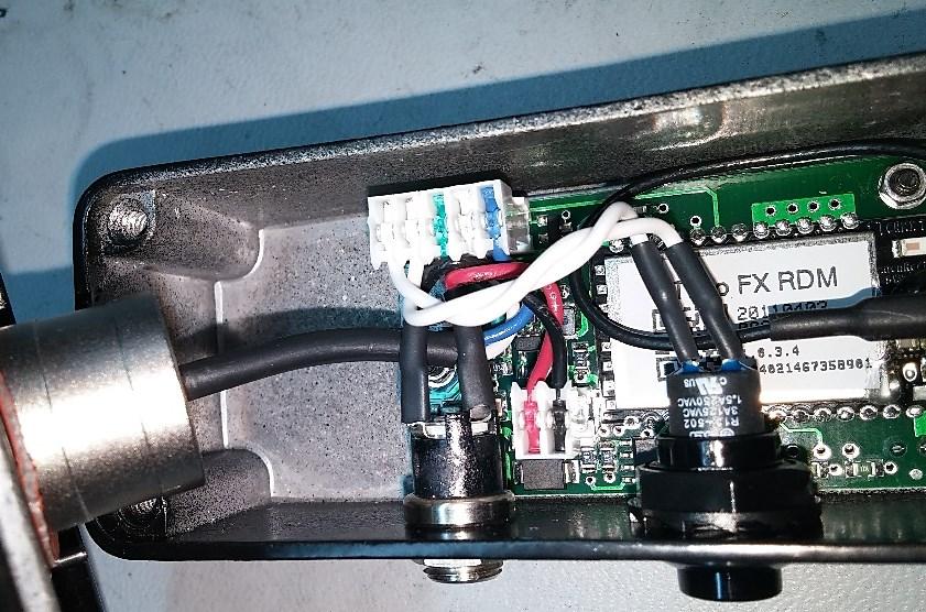
11 Step 1: Remove 4 screws located on each corner of the back of the Cintenna and open the chassis. Begin by unplugging RF Link, Power and XLR connector in that order. Take note of how the connectors are installed so that they me be re inserted correctly upon completion of repair. Fig. 1- Here you can see the wire orientation of the XLR connector and components. Step 2: With the XLR back plate out of the way, loosen up the nuts and remove both the charging port (3/8) and the RF Link button (9/16). Once both components are removed, loosen the (5/8) nut on the outside of the chassis for the antenna connector for removal. Now
 nut.")
 Fig.")
12 remove the nuts securing the circuit board down to the chassis and pull out the board just enough to remove antenna wire connection. Re attach the new antenna connector and apply hot glue on the wire connector in the position shown before proceeding to secure new antenna connector with (5/8) nut. Be sure to include the lock washer on the outside of the chassis when installing the new antenna connector. Fig. 2- Remove the black plastic nut (9/16) for the RF link button. Do not over tighten when re installing or the button push action will not be smooth. Also remove the silver nut for the charging port (3/8) Fig. 3 The antenna connector should have a lock washer on the outside on the chassis before the (5/8) nut. Step 3- Now that the new antenna connector is installed, re secure the circuit board down to the chassis while making sure that the antenna wire is still Fig 4- Notice the routing of the antenna wire as well as the direction that the connector is facing once secured. Fig. 5- Be sure to run the blue and white wires for the XLR connector underneath the wires for the charging port.
13 looped and free of tension. Be sure to apply hot glue over the antenna wire connector once installed. Tighten down the nuts on the circuit board and begin to re install the RF link button and the charging port. Once all components are re installed, plug the XLR, RF Link and charging port back into the circuit board. Close the chassis and be mindful not

14 pinch any of the components wiring.
M5 and M10 Routers Power Supply and Power Cord Component Replacement Instructions
 M5 and M10 Routers Power Supply and Power Cord Component Replacement Instructions Part No. 530-003244-01 Revision 1 27 July 2000 This document describes how to remove and replace the AC and DC power supplies,
Elecraft K3 KPA3 Power Connector Replacement Revision B, June 30, 2017 Copyright 2017, Elecraft, Inc. All Rights Reserved
 Introduction Elecraft K3 KPA3 Power Connector Replacement Revision B, June 30, 2017 Copyright 2017, Elecraft, Inc. All Rights Reserved The connectors furnishing high current to the KPA3 module have failed
TIVO UPGRADE INSTRUCTIONS (c) , Adberg Consulting LLC. All rights reserved.
 , Adberg Consulting LLC. All rights reserved.") TIVO UPGRADE INSTRUCTIONS (c) 2001-2003, Adberg Consulting LLC. All rights reserved. Instructions for Series 1 DirecTV/TiVo GXCEBOT TWO-DRIVE REPLACE upgrade Color instructions are also available at http://www.weaknees.com/upgrade_instructions.php
TIVO UPGRADE INSTRUCTIONS (c) 2001-2003, Adberg Consulting LLC. All rights reserved. Instructions for Series 1 DirecTV/TiVo GXCEBOT TWO-DRIVE REPLACE upgrade Color instructions are also available at http://www.weaknees.com/upgrade_instructions.php
Prisma II Chassis 56-Port Upgrade Technical Bulletin
 Prisma II Chassis 56-Port Upgrade Technical Bulletin Overview Audience Introduction This technical bulletin applies to all cable system operators and technicians who use the Prisma II Chassis configured
HP Pavilion dv7-6c90us Cooling fan Replacement
 HP Pavilion dv7-6c90us Cooling fan Replacement This guide will walk you through the process of replacing the cooling fan in an HP Pavilion dv7 laptop. Written By: Angelina Clayton ifixit CC BY-NC-SA www.ifixit.com
Written By: John Sutton
 Replacing the fan on your HP g7-2275 dx. Written By: John Sutton ifixit CC BY-NC-SA www.ifixit.com Page 1 of 20 INTRODUCTION Laptop cooking your lap? This guide will walk you through replacing your fan.
Huawei Ascend P6-U06 Screen/LCD Display Replacement
 Huawei Ascend P6-U06 Screen/LCD Display Replacement Replace the Huawei Ascend P6-U06's screen and LCD display. Written By: Zachary Rose ifixit CC BY-NC-SA www.ifixit.com Page 1 of 17 INTRODUCTION Replace
Canon EOS Rebel T2i Top Cover Replacement
 Canon EOS Rebel T2i Top Cover Replacement Replacing the top piece of a Canon T2i (550D). In my case, I had a broken hot-shoe, but as most controls on this camera are built into the same part, this repair
Megatouch FORCE Monitor Chassis Board Replacement
 Megatouch FORCE Monitor Chassis Board Replacement Visit the Merit Industries, Inc. Web site http://www.meritind.com merit industries, inc. PM0337-01 Rev C Table of Contents FORCE Classic Monitor Chassis
Replacement Instructions
 imac G5 Inverter, 20-inch Replacement Instructions Follow the instructions in this document carefully. Failure to follow these instructions could damage your equipment and void its warranty. Note: Online
Z-Truck (Vertical Moving) Z-truck Flag. Y-Truck (Horizontal Moving) FIGURE 1: VIEW OF THE Z-TRUCK. Flexshaft Assembly
 Z-truck Flag. Y-Truck (Horizontal Moving) FIGURE 1: VIEW OF THE Z-TRUCK. Flexshaft Assembly") Replacing the LCD Cable To remove and replace the LCD Cable you will need the following tools: #2 Phillips screwdriver (magnetic tip preferred) Socket wrench with 10mm socket Removing the Side Panel 1.
Replacing the LCD Cable To remove and replace the LCD Cable you will need the following tools: #2 Phillips screwdriver (magnetic tip preferred) Socket wrench with 10mm socket Removing the Side Panel 1.
How to Perform an IBM ThinkPad X60s Fan Spindle Replacement
 How to Perform an IBM ThinkPad X60s Fan Spindle Replacement This guide details an IBM ThinkPad X60s fan spindle replacement. Written By: Samuel Lees ifixit CC BY-NC-SA www.ifixit.com Page 1 of 10 INTRODUCTION
Q2 XBee Handheld Controller Assembly Guide
 Q2 XBee Handheld Controller Assembly Guide Copyright Quantum Robotics Inc. Q2 Controller V1.0 1 Parts List: The kit comes with 14 individual bags. 1. Case Top and Bottom 2. Case Screw Package containing:
Dell Inspiron 1525 Upper Case Replacement
 Dell Inspiron 1525 Upper Case Replacement Replace the upper case on a Dell Inspiron 1525. Written By: Miroslav Djuric ifixit CC BY-NC-SA www.ifixit.com Page 1 of 13 INTRODUCTION Use this guide to help
Nintendo 3DS XL 2015 Upper Screen
 Nintendo 3DS XL 2015 Upper Screen Replacement Showing how to replace the Upper Screen of the Nintendo 3DS XL. Written By: Ryan Butler ifixit CC BY-NC-SA www.ifixit.com Page 1 of 13 INTRODUCTION This guide
SERVICE BULLETIN No. 24. For CAREpoint Workstation (Winsystems PC Modules Only)
") SERVICE BULLETIN No. 24 For CAREpoint Workstation (Winsystems PC Modules Only) Title: Swapping a CD/DVD Rom Drive Please read the following instructions before proceeding. Priority: Service Reference:
SERVICE BULLETIN No. 24 For CAREpoint Workstation (Winsystems PC Modules Only) Title: Swapping a CD/DVD Rom Drive Please read the following instructions before proceeding. Priority: Service Reference:
Huawei Ascend P6-U06 Earpiece Speaker Replacement
 Huawei Ascend P6-U06 Earpiece Speaker Replacement Replace the Huawei Ascend P6-U06 earpiece speaker. Written By: Oren Klein ifixit CC BY-NC-SA www.ifixit.com Page 1 of 11 INTRODUCTION Replace your phone's
imac Intel 27" EMC 2639 Hard Drive
 imac Intel 27" EMC 2639 Hard Drive Replacement Replace the Hard Drive in your imac Intel 27" EMC 2639. Written By: Walter Galan ifixit CC BY-NC-SA www.ifixit.com Page 1 of 26 INTRODUCTION Replacing the
Serial ATA Hot Swap Drive Cage Upgrade Kit for: Intel Server Chassis SC5200 Intel Server Chassis SC5250-E
 Serial ATA Hot Swap Drive Cage Upgrade Kit for: Intel Server Chassis SC5200 Intel Server Chassis SC5250-E A Guide for Technically Qualified Assemblers of Intel Identified Subassemblies/Products Order Number:
Electronic Balance Ionizer STABLO-AP Service Manual
 321-78209 Jan. 2016 Electronic Balance Ionizer STABLO-AP Service Manual Analytical & Measuring Instruments Division This page is intentionally left blank. Table of Contents 1. Precautions for Troubleshooting...
Elecraft W1 SWR/Wattmeter Enclosure by W8FGU
 Elecraft W1 SWR/Wattmeter Enclosure by W8FGU The W1 enclosure is made of Lexan, a polycarbonate, which is very strong. It also has a UV blocking coating on one side and was assembled carefully with this
Huawei Ascend P6-U06 Motherboard Replacement
 Huawei Ascend P6-U06 Motherboard Replacement Replace the Huawei Ascend P6-U06 motherboard. Written By: Victor Munoz ifixit CC BY-NC-SA www.ifixit.com Page 1 of 13 INTRODUCTION Replace the motherboard to
Huawei Ascend P6-U06 Screen/LCD Display Replacement
 Huawei Ascend P6-U06 Screen/LCD Display Replacement Replace the Huawei Ascend P6-U06's screen and LCD display. Redigido por: Zachary Rose ifixit CC BY-NC-SA pt.ifixit.com Página 1 de 17 INTRODUÇÃO Replace
ipod Classic Headphone Jack & Hold Switch Replacement
 ipod Classic Headphone Jack & Hold Switch Replacement Replace Headphone Jack & Hold Switch to fix no audio and/or no unlock Written By: irobot ifixit CC BY-NC-SA www.ifixit.com Page 1 of 22 INTRODUCTION
ATTENTION: OBSERVE PRECAUTIONS FOR HANDLING ESD-SENSITIVE DEVICES
 15 Monitor Removal 1. Turn off and unplug the game. 2. Place something in front of the game to brace the bezel once the strain relief cord is undone, then unlock and open the CPU section. 3. Remove the
A TCP/IP network CAT 5 cable If the network is faster than 10baseT a switching hub will be needed Static IP address
 Requirements A TCP/IP network CAT 5 cable If the network is faster than 10baseT a switching hub will be needed Static IP address Power Up A Reader with an Ethernet adaptor installed and the network cable
IPhone 7 Plus Chargeport REPAIR GUIDE. Version Edition
 IPhone 7 Plus Chargeport REPAIR GUIDE Version 1 2016 Edition IPhone 7 plus Chargeport Repair Guide RiAna Soto Repair Training Specialist rsoto@cellairis.com FOR EVERY REPAIR MAKE SURE TO COMPLETE, INITIAL,
Written By: Walter Galan
 imac Intel 21.5" EMC 2428 CPU Replacement Replace the CPU in your imac Intel 21.5" EMC 2428. Written By: Walter Galan ifixit CC BY-NC-SA www.ifixit.com Page 1 of 33 INTRODUCTION Use this guide to upgrade
Replacement Keyswitch Assembly
 Installation Instructions Replacement Keyswitch Assembly (Catalog No. 2711E-NKSW1) Applicable Terminals Use this replacement keyswitch with PanelView Terminals 2711-KA1, -KC1, -TA1, -TC1, -TA4, -TC4 and
To connect the AC adapter:
 Replacing the AC Adapter Replacing the AC Adapter 3 Plug the power cord into a wall outlet. The power indicator turns on. To connect the AC adapter: Connect the power cord to the AC adapter. Power indicator
Replacing the PanelMate Power Pro 1785 Series, PanelMate epro 7585x-8 and 7685x-8 Series Backlight Assembly
 Replacing the PanelMate Power Pro 1785 Series, PanelMate epro 7585x-8 and 7685x-8 Series Assembly Introduction The Replacement Kit provides a replacement backlight for the PanelMate Power Pro 1785 Series,
OnePlus 5 Screen and Digitizer Assembly Replacement
 OnePlus 5 Screen and Digitizer Assembly Replacement Follow this guide to replace the screen and digitizer for the OnePlus 5. This replaces the screen as well as the frame it is attached to. Written By:
A-dec 570L Dental Light on a DCS System INSTALLATION GUIDE
 A-dec 570L Dental Light on a DCS System INSTALLATION GUIDE C ONTENTS Choose an Installation Guide...... Before You Begin.............. 3 Disconnect the Light Cable........ 3 Cut the Light Cable............
ibook G4 12" 800 MHz-1.2 GHz RJ-11 Board
 ibook G4 12" 800 MHz-1.2 GHz RJ-11 Board Replacement Written By: irobot ifixit CC BY-NC-SA www.ifixit.com Page 1 of 24 INTRODUCTION The standard telephone jack port for connecting to the 56k internal modem.
apple Service Source PowerBook G4 Updated 8 July Apple Computer, Inc. All rights reserved.
 apple Service Source PowerBook G4 Updated 8 July 2003 2003 Apple Computer, Inc. All rights reserved. apple Service Source Take Apart PowerBook G4 2003 Apple Computer, Inc. All rights reserved. apple PowerBook
Written By: Andrew Bookholt
 PlayStation 3 Slim Heat Sink Replacement Replace your PS3 Slim's heat sink and its integrated fan shroud. Written By: Andrew Bookholt ifixit CC BY-NC-SA www.ifixit.com Page 1 of 21 INTRODUCTION Use this
MacBook Pro 17" Unibody AirPort Board Replacement
 MacBook Pro 17" Unibody AirPort Board Replacement Replace the AirPort Board in your MacBook Pro 17" Unibody. Written By: Brett Hartt ifixit CC BY-NC-SA www.ifixit.com Page 1 of 15 INTRODUCTION Having issues
Section. Service & Maintenance. - Core & Hard Disk Drive (HDD) - Amplifier - Monitor - UPS - Dollar Bill Acceptor - Fan Filter G - 1
 - Amplifier - Monitor - UPS - Dollar Bill Acceptor - Fan Filter G - 1") Section G Service & Maintenance - Core & Hard Disk Drive (HDD) - Amplifier - Monitor - UPS - Dollar Bill Acceptor - Fan Filter G - 1 Core Removal Core & HDD 1. Open the door. 2. Perform shutdown procedure.
Section G Service & Maintenance - Core & Hard Disk Drive (HDD) - Amplifier - Monitor - UPS - Dollar Bill Acceptor - Fan Filter G - 1 Core Removal Core & HDD 1. Open the door. 2. Perform shutdown procedure.
Upgrading and Servicing Guide
 Upgrading and Servicing Guide The only warranties for Hewlett-Packard products and services are set forth in the express statements accompanying such products and services. Nothing herein should be construed
When you are ready to build your computer you will have the following materials to work with.
 Copyright 2009 BOSMA Enterprises Chapter 3 Putting the Computer Together When you are ready to build your computer you will have the following materials to work with. 1. One motherboard. 2. One ribbon
MCH WIRE HARNESS WITH QUICK DISCONNECT REPLACEMENT Initial Release 1/31/2013
 1. Table of Contents 1. Table of Contents Page 1 2. Remove Failed MCH-103.2 Page 1 3. Install MCH-103.2 to MCH-102NW Page 2 4. Install NC3FX-HD to MCH-103.2 Page 3 5. Install MCH-103.2 Battery Terminal
Toshiba Satellite L305-S5946 Power Jack Replacement
 Toshiba Satellite L305-S5946 Power Jack Replacement Replace the power jack in your Toshiba Satellite L305-S5946. Written By: Michael Erberich ifixit CC BY-NC-SA www.ifixit.com Page 1 of 16 INTRODUCTION
Huawei Ascend P6-U06 Micro-USB Flex Cable Replacement
 Huawei Ascend P6-U06 Micro-USB Flex Cable Replacement Replace the Huawei Ascend P6-U06 Micro-USB flex cable. Rédigé par: Chase Hemming ifixit CC BY-NC-SA fr.ifixit.com Page 1 de 10 INTRODUCTION Replace
Elecraft K3 KREF3 Output Level Modification
 Elecraft K3 Revision A, September 15, 2015 Copyright 2015, Elecraft, Inc. All Rights Reserved Introduction This modification increases the output levels from the KREF3 Reference Oscillator to provide proper
OLPC XO-4 Touch Touchpad Controller Replacement
 OLPC XO-4 Touch Touchpad Controller Replacement This guide will walk through replacing a touchpad. Written By: Theodore Tsanakas ifixit CC BY-NC-SA www.ifixit.com Page 1 of 13 INTRODUCTION Use this guide
Kindle Fire Dismantling Instructions
 Kindle Fire Dismantling Instructions These instructions will show you how to open the Kindle Fire to replace the screens and other internal parts. Opening your Kindle will void your warrantee, and ConsoleParts4U
PowerBook G4 Aluminum 12" GHz Left Clutch Hinge Replacement
 PowerBook G4 Aluminum 12" 1-1.5 GHz Left Clutch Hinge Replacement Written By: Matthew Newsom ifixit CC BY-NC-SA www.ifixit.com Page 1 of 50 INTRODUCTION Replace a broken clutch hinge to make your display
Removing and Replacing Parts
 Removing and Replacing Parts Preparing to Work Inside the Computer Recommended Tools Screw Identification System Components Hard Drive Fixed Optical Drive Media Bay Devices Memory Modules Mini PCI Card
Installing 6 Indexer: PRS Standard Tools
 888-680-4466 ShopBotTools.com Installing 6 Indexer: PRS Standard Tools Copyright 2016 ShopBot Tools, Inc. page 1 Copyright 2016 ShopBot Tools, Inc. page 2 Table of Contents Overview...5 Installing the
Removal and Installation8
 8 Screw Types 8-4 Top Cover Assembly 8-5 Left Hand Cover 8-6 Right Hand Cover 8-10 Front Panel Assembly 8-14 Left Rear Cover 8-15 Right Rear Cover 8-16 Extension Cover (60" Model only) 8-17 Media Lever
Motorola Moto G4 Plus Motherboard Replacement
 Motorola Moto G4 Plus Motherboard Replacement Remove and replace your motherboard as a prerequisite to other guides. Written By: Andre Rives ifixit CC BY-NC-SA www.ifixit.com Page 1 of 11 INTRODUCTION
Experimental Procedure
 1 of 14 9/10/2018, 11:38 AM https://www.sciencebuddies.org/science-fair-projects/project-ideas/robotics_p028/robotics/obstacle-avoiding-robot (http://www.sciencebuddies.org/science-fair-projects /project-ideas/robotics_p028/robotics/obstacle-avoiding-robot)
Nintendo 3DS XL 2015 Motherboard
 Nintendo 3DS XL 2015 Motherboard Replacement This guide details how to access and remove the motherboard. Written By: Zoe Cagle ifixit CC BY-NC-SA www.ifixit.com Page 1 of 11 INTRODUCTION The motherboard
A how-to guide for replacing the DJI Phantom 4 body shell. *Replacing the body shell could also be used as a tear-down guide. Written By: GotMac
 A how-to guide for replacing the DJI Phantom 4 body shell. *Replacing the body shell could also be used as a tear-down guide. Written By: GotMac ifixit CC BY-NC-SA www.ifixit.com Page 1 of 15 INTRODUCTION
G12/G12x USER S MANUAL
 G12/G12x USER S MANUAL TABLE OF CONTENTS SECTION 1 SLIDE CONFIGURATION SECTION 2 SLIDE CONFIGURATION ACCESSORIES SECTION 3 TABLETOP CONFIGURATION SECTION 4 TABLETOP CONFIGURATION ACCESSORIES SECTION 5
Intel NUC Kit D54250WYKH & D34010WYKH User Guide. Intel NUC Kit D54250WYKH Intel NUC Kit D34010WYKH User Guide
 Intel NUC Kit D54250WYKH Intel NUC Kit D34010WYKH User Guide 1 Before You Begin CAUTIONS The procedures in this user guide assume familiarity with the general terminology associated with personal computers
ipad Mini Wi-Fi Front Facing Camera Replacement
 ipad Mini Wi-Fi Front Facing Camera Replacement Replace the Front Facing Camera in your ipad Mini Wi-Fi. Written By: Andrew Optimus Goldberg ifixit CC BY-NC-SA www.ifixit.com Page 1 of 42 INTRODUCTION
Installation Guide. Retrofit Kit for USB Ready Intraoral Systems
 Installation Guide Retrofit Kit for USB Ready Intraoral Systems Table of Contents Wall-Mount Retrofit Kit... 2 Introduction... 2 Connecting the Articulating and Horizontal Arm Cables... 2 Installing the
Written By: Wei Xia. This guide will teach you how to replace the power button. OLPC XO-1.5 Power Button Replacement
 OLPC XO-1.5 Power Button Replacement This guide will teach you how to replace the power button. Written By: Wei Xia ifixit CC BY-NC-SA www.ifixit.com Page 1 of 13 INTRODUCTION If your OLPC does not turn
Written By: Nicole Welter
 HP Pavilion G60-630US Screen Replacement In this guide, we will be replacing a faulty or unresponsive screen. Written By: Nicole Welter ifixit CC BY-NC-SA www.ifixit.com Page 1 of 14 INTRODUCTION The screen
Nintendo 3DS D-pad Replacement
 Nintendo 3DS D-pad Replacement Nintendo 3DS D-pad replacement. Written By: David Hodson ifixit CC BY-NC-SA www.ifixit.com Page 1 of 15 INTRODUCTION Replace the D-pad on your 3DS to get full movement capabilities
FLOE WIRELESS REMOTE ASSEMBLY INSTRUCTIONS KIT P/N
 FLOE WIRELESS REMOTE ASSEMBLY INSTRUCTIONS KIT P/N 5-0083-00 TOOLS REQUIRED - 3/4" SOCKET - 3/4" WRENCH - /3" WRENCH - PHILLIPS SCREW DRIVER - TORQUE WRENCH INSTRUCTION P/N 6-0083-00 ISSUED: 3//7 SHEET
Nintendo 3DS XL 2015 Directional Pad Replacement
 Nintendo 3DS XL 2015 Directional Pad Replacement This guide will give instruction on how to replace the directional pad on a Nintendo 3DS XL 2015 Written By: Thomas Cho ifixit CC BY-NC-SA www.ifixit.com
PowerBook G4 Aluminum 12" GHz Display Data Cable Replacement
 PowerBook G4 Aluminum 12" 1-1.5 GHz Display Data Cable Replacement Written By: Matthew Newsom ifixit CC BY-NC-SA www.ifixit.com Page 1 of 47 INTRODUCTION Replace a damaged display data cable to restore
NEVER operate winch with less than 10 wraps of rope around the drum. The terminal end is to prevent the rope from unraveling, it is NOT a load
 X2O Winches NEVER operate winch with less than 10 wraps of rope around the drum. The terminal end is to prevent the rope from unraveling, it is NOT a load bearing attachment point. Improper installation
ENCORE /ST G4. Processor Upgrade Card for Power Mac G4 AGP Graphics. Quick Start Guide for Encore/ST G4
 ENCORE /ST G4 Processor Upgrade Card for Power Mac G4 AGP Graphics Quick Start Guide for G4 Power Mac and Operating System Compatibility This G4 processor upgrade is compatible only with Power Mac G4 AGP
Nook Tablet Display Replacement
 Nook Tablet Display Replacement Written By: Michael Mooney ifixit CC BY-NC-SA www.ifixit.com Page 1 of 12 INTRODUCTION This guide will show easy ways to access the nook tablet visual display, replace the
Nov. 07, 2013 p. 5 - changed the B axis unit value to from Changed by Randy per Frank s request.
 Correction notes Nov. 07, 2013 p. 5 - changed the B axis unit value to 45.1389 from 40.0000. Changed by Randy per Frank s request. Jan. 22, 2018 p. 5 - changed the B axis unit value and corresponding picture
Upgrading and Servicing Guide
 Upgrading and Servicing Guide The information in this document is subject to change without notice. Hewlett-Packard Company makes no warranty of any kind with regard to this material, including, but not
Shift Dismantling Guide
 Tools: Torx T6 screwdriver Case Opening Tool (optional) Torx T5. (required for screen disassembly Normal anti-static precautions should be taken Shift Dismantling Guide by facdemol member at XDA-Developers.com
imac Intel 27" Retina 5K Display CPU Replacement
 imac Intel 27" Retina 5K Display CPU Replacement Replace or upgrade the CPU in your imac Intel 27" Retina 5K Display. Written By: Sam Lionheart ifixit CC BY-NC-SA www.ifixit.com Page 1 of 36 INTRODUCTION
3G Cell Modem Installation and User Guide
 3G Cell Modem Installation and User Guide For BaseStation 1000 & BaseStation 3200 Irrigation Controllers in X and XS Cabinets April 24, 2017 Customer Service 1-866-294-5847 Baseline Inc. www.baselinesystems.com
Reflowing Xbox 360 Motherboard
 Reflowing Xbox 360 Motherboard Reflow the solder on your Xbox 360's motherboard. Written By: Andrew Bookholt ifixit CC BY-NC-SA www.ifixit.com Page 1 of 31 INTRODUCTION Use this guide to reflow the solder
Canon Powershot SD550 Zoom Lens Assembly Replacement
 Canon Powershot SD550 Zoom Lens Assembly Replacement This repair guide will show you how to take apart the PowerShot SD550 and replace the zoom lens. Written By: Matthew Theiss ifixit CC BY-NC-SA www.ifixit.com
Macintosh PowerBook 165c Motherboard Replacement
 Macintosh PowerBook 165c Motherboard Replacement This guide will demonstrate how to replace the Macintosh PowerBook 165c Motherboard. Written By: John ifixit CC BY-NC-SA www.ifixit.com Page 1 of 15 INTRODUCTION
Moto G4 LCD Screen and Digitizer Assembly Replacement
 Moto G4 LCD Screen and Digitizer Assembly Replacement Replace a cracked or faulty display as a complete assembly, including the surrounding frame/chassis. Written By: Richard Gonzalez ifixit CC BY-NC-SA
PlayStation 3 Teardown PS3. Written By: Mint137. ifixit CC BY-NC-SA Page 1 of 22
 PlayStation 3 Teardown PS3 Written By: Mint137 ifixit CC BY-NC-SA www.ifixit.com Page 1 of 22 INTRODUCTION This is a teardown of an original launch 60GB PlayStation 3 system. One of the best units out
Nintendo DSi Touch Screen / Bottom LCD Replacement
 Nintendo DSi Touch Screen / Bottom LCD Replacement Disassembly and replacement of the lower LCD / touch screen Written By: bushing ifixit CC BY-NC-SA www.ifixit.com Page 1 of 15 INTRODUCTION This guide
Gateway Profile 4 service guide
 Gateway Profile 4 service guide Customizing Troubleshooting Contents Replacing Components in Your Gateway Profile 4.................. 1 About this guide.....................................................
User s Guide TURBO Pinewood Derby Finish Line and Timer Release /31/2011 NewBold Products, Atlanta GA
 User s Guide TURBO Pinewood Derby Finish Line and Timer Release 2.1 12/31/2011 NewBold Products, Atlanta GA www.newboldproducts.com 2 1. YOUR SHIPMENT Thank you for purchasing the TURBO, Pinewood Derby
ibook G4 14" 933 MHz-1.33 GHz Hard Drive
 ibook G4 14" 933 MHz-1.33 GHz Hard Drive Replacement Written By: irobot ifixit CC BY-NC-SA www.ifixit.com Page 1 of 25 INTRODUCTION You can install hard drives up to 9.5mm thick. TOOLS: Coin (1) Phillips
Instructions for installing your QuiltCam on your Gammill quilt machine.
 Instructions for installing your QuiltCam on your Gammill quilt machine. The items include with your QuiltCam Items included in all packages: QuiltCam Control Box, See Figure 1 Power Supply, Figure 2 Video
LED. Sign Module. Assembly Manual
 LED Sign Module Assembly Manual 6/14/2002 3:10 PM 6 2 3 3 E. S a w g ra s s R d S a ra s o ta, F L. 3 4 2 4 0 (9 4 1 )3 7 7-5 7 7 5 F A X(9 4 1 )3 7 8-4 2 2 6 www.acscontrol.com Table of Contents Table
Intel NUC Kit DN2820FYKH User Guide. Intel NUC Kit DN2820FYKH User Guide
 Intel NUC Kit DN2820FYKH User Guide 1 Before You Begin CAUTIONS The procedures in this user guide assume familiarity with the general terminology associated with personal computers and with the safety
efolder Replibit Pro Appliance Maintenance Manual (Pro 3000, 6000, 9000, and models) Replibit Pro Appliance Maintenance Manual
 Replibit Pro Appliance Maintenance Manual") efolder Replibit Pro Appliance Maintenance Manual (Pro 3000, 6000, 9000, 12000 and 15000 models) 2016 efolder, Inc. All rights reserved. Last Update: November 2016 Page 1 Customer Support At efolder, we
efolder Replibit Pro Appliance Maintenance Manual (Pro 3000, 6000, 9000, 12000 and 15000 models) 2016 efolder, Inc. All rights reserved. Last Update: November 2016 Page 1 Customer Support At efolder, we
imac Intel 27" EMC 2429 SSD Dual Drive
 imac Intel 27" EMC 2429 SSD Dual Drive Installation Install the dual hard drive kit in an imac Intel 27" EMC 2429. Written By: Dozuki System 2017 guides.crucial.com Page 1 of 22 INTRODUCTION This guide
MacBook Pro 13" Function Keys Late 2016 Trackpad Replacement
 MacBook Pro 13" Function Keys Late 2016 Trackpad Replacement Remove or replace the trackpad in your non-touch Bar MacBook Pro (13-inch, 2016, Two Thunderbolt 3 ports). Written By: Jeff Suovanen ifixit
Written By: Walter Galan
 Replace a cracked screen on your iphone 4S. Written By: Walter Galan ifixit CC BY-NC-SA www.ifixit.com Page 1 of 32 INTRODUCTION Use this guide to replace the screen on your iphone 4S. After successfully
25 Sport Scope Instruction Manual
 25 Sport Scope Instruction Manual Dear Customer, We appreciate your business and value your support for our product. At Sport Scope, we strive to provide our customers with quality, easy to use, and affordable
Installing the Server into a Rack
 Installing the Server into a Rack Note These instructions apply to multiple models; illustrations may vary slightly. Rack Mount Kit Inventory Before installing the chassis on a standard 4-post rack, make
Dell Latitude C800 Service Manual
 Dell Latitude C800 Service Manual Dell Latitude C800 Service Manual Before You Begin Preparing to Work Inside the Computer Recommended Tools Screw Identification Removing and Replacing Parts System Components
itech Training Courses iphone 5S LCD Assembly Replacement Guide
 itech Training Courses iphone 5S LCD Assembly Replacement Guide 2014 icracked, Inc. All rights reserved. ios, all Apple product names, and Apple logos are trademark property of Apple, Inc. The content
Written By: Sam Lionheart
 iphone SE Display Assembly Replacement Replace the cracked or broken screen on your iphone SE. Written By: Sam Lionheart ifixit CC BY-NC-SA www.ifixit.com Page 1 of 26 INTRODUCTION Use this guide to replace
Cube Installation Kit Manual ENCORE /ST G4
 Cube Installation Kit Manual ENCORE /ST G4 Installation Manual Cube Dealer Installation Kit for ENCORE /ST G4 Installation Manual Cube Dealer Installation Kit 2002 Sonnet Technologies, Inc. All rights
 This tutorial was written by Team Xecuter. If you use anything from this tutorial please give credits and also a direct link to this page. Also if we have made any mistakes or left anything out please
AC LEISURE PRO SHORE COMMANDER
 AC LEISURE PRO SHORE COMMANDER ( BLACK CONTROL BOX ) Troubleshooting Guide Picture shown below is a vertical mount system INDEX 1.0 Power recommendations Licensed Electrician 1.1 Power recommendations
Figure 4-29 Removing the CPU compartment cover
 4 Replacement Procedures 4.9 CPU 4 4.9 CPU Removing the CPU To remove the CPU, follow the steps below. 1. Turn the computer upside down and remove two M2.5 4 security screws securing the CPU compartment
If technical support is required, please contact Advent Technical Support at
 Document 128-9011 Created 11/21/11 Kit Contents: Item # Qty. Component Description 1 2 Monitor Assembly 2 2 Remote Control 3 1 Cables # 3 4 1 Metal Wire Puller 5 1 Power Cord # 9 6 1 Owners Manual 7 2
ThinkCentre. Hardware Removal and Replacement Guide Types 8143, 8144, 8146 Types 8422, 8423, 8427
 ThinkCentre Hardware Remoal and Replacement Guide Types 8143, 8144, 8146 Types 8422, 8423, 8427 ThinkCentre Hardware Remoal and Replacement Guide Types 8143, 8144, 8146 Types 8422, 8423, 8427 First Edition
Parts List: Assembly Instructions:
 My Ride SERVICE MANUAl MyRide ASSEMBLY GUIDE 1.1 ASSEMBLY INSTRUCTIONS ASSEMBLING THE MYRIDE Parts List: Heavy Plate Stabilizer Fin - Right Stabilizer Fin - Left Stabilizer Fin - Large Middle Power Cord