CPI installation system
|
|
|
- Clarissa June Beasley
- 6 years ago
- Views:
Transcription
1

2 Key features Key features Innovative Sturdy Versatile Reliable Complete concept for decentralised machine and system structure; centralised and decentralised installation can be combined with the CPX terminal Decentralised pneumatics and sensors for fast processes Centralised electrics for fieldbus and common power supply Flexible configuration of the individual CP strings Selectable valve terminal sizes for optimum pneumatic control loop systems Performance data as for the CP system with the addition of the comprehensive diagnostic capabilities of the CPX terminal Electrical accessories to IP65 Proven valve terminals CPV (compact), MPA-S (sturdy, modular), CPV-SC (small, compact) Electrical input and output modules in metal housing or compact in encapsulated plastic housing Sturdy connection technology M12, alternatively M8 IP20 modules for control cabinet installation with spring-loaded terminals or screw terminals A number of CP interfaces can be combined under one fieldbus node Four CP strings up to 10 m in length (radius) facilitate optimum decentralisation Max. 32 inputs and 32 outputs/ valves per string Available valves: Valve terminal MPA-S, flow rate max. 700 l/min Valve terminal CPV, flow rate max l/min Valve terminal CPV-SC, flow rate max. 170 l/min Valve terminals with I-Port interface (VTUG, CPV, MPA-L, VTUB-12, VTOC) Input modules with 8 32 inputs and output modules with 4 8 outputs, each with or without additional power supply Sturdy modules and accessories Ready to install system including CP cable (hybrid cable for data and power) Polarity-safe and short circuit proof connections Valves with separate load voltage supply All modules equipped with local diagnostics and status LEDs Diagnostics of each CP string via controller/fieldbus Intelligent system (save button) learns current configuration Easy replacement of modules at any time 2 Internet: Subject to change 2017/10
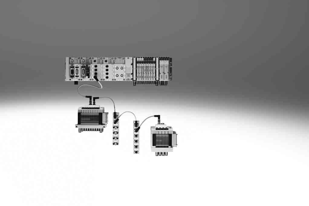
3 Key features CPI installation system The CPI system is capable of meeting two completely different requirements and resolves the conflict between extensive decentralised modularisation and electrical installation. High-speed machines require short cycle times and short pneumatic tubing. The valves must be mounted close to the cylinders. The CPI system was developed to meet these requirements without having to wire each valve individually. The system integrates the modular valve terminals CPV and various input/output modules in a single installation concept. All CP valve terminals and CP modules are connected using a ready to install CP cable, and are attached to the CP interface. Four modules, for example one CPV valve terminal and one to three CP input modules, make up an installation string that ends at the CP interface. Scope of features: Max. 4 installation strings per CP interface Max. 10 metre line length per string (radius) Max. 4 CP modules per string Max. 32 inputs and max. 32 outputs per string The number of CP modules that can be connected and the number of inputs/ outputs is dependent on the type of CP module and CP interface. The maximum configuration (4 modules per string, 32 inputs/outputs) is only possible in combination with the CPX terminal and CP modules with CPI functionality. The CP interface is the central connection point for the valve power supply and the sensor supply. The power supply for the sensors connected to the input modules is separate from the load voltage of the valves. 2017/10 Subject to change Internet: 3
4 Key features Node types Fieldbus CPX with CP interface CPX- Valve terminal with CP string extension CPV, CPV-SC, MPA-S Configurator Selecting a CPI system using the online catalogue is quick and easy thanks to the convenient configurator provided. This makes it much easier to find the right product. Components from the CPI system series, type CTEC, are ordered using the order code. Ordering system for type 55E Internet:ctec Online via: 4 Internet: Subject to change 2017/10
5 Peripherals overview Integration of the CPI installation system in various connection concepts Centralised pneumatic connection (valve terminal) Advantages Pneumatic multiple connector plate Less tubing required than with individual valves Common valve air supply Central positioning Material, weight and cost savings Disadvantages Only effective with a large number of closely spaced actuators Heavier than an individual valve (lower overall weight than the same number of individual valves), which may make assembly on moving systems or in very cramped installation spaces difficult Longer tube lengths are occasionally required, ruling out the possibility of optimum pneumatic performance Decentralised pneumatic connection (individual valve/valve on individual sub-base) Advantages Can be positioned directly at the actuator, can even be integrated Short tubing length to the actuator enables short switching times Optimum pneumatic timing and performance possible Disadvantages Air supply per valve requires more tubing Serial electrical interlinking not advisable/possible More complex electrical installation Centralised electrical connection (multi-pin plug/bus connection/standalone minicontroller) Advantages Internal electrical interlinking requires less cabling Increased transparency Material, weight and cost savings Ideal for connecting a large number of closely spaced valves Disadvantages Not suitable for individual, more widely separated applications due to the more complex cabling More complex individual components (cables, fieldbus modules) 2017/10 Subject to change Internet: 5
6 Peripherals overview Integration of the CPI installation system in various connection concepts Decentralised electrical connection (CPI system/individual valve/valve on individual sub-base/valve manifold) Advantages CPI system with reduced installation complexity for groups of actuators/sensors Different levels of complexity with widely separated individual components Easy replacement of components during servicing Optimum pneumatic timing and performance possible Disadvantages Limited spatial expansion possible (CPI system up to 10 m, AS-interface up to 100 m) High installation costs Combined centralised and decentralised connection (valve terminal with CP interface/output module) Advantages Can be scaled to different requirements within a system One control interface in the system, reduces installation complexity with closely and widely spaced actuators Enables an optimum electrical and pneumatic control chain Disadvantages Application must at least partially meet the requirements of a centralised connection Connection of the CPI installation system to a higher-level controller Bus node/industrial Ethernet Different bus nodes are used for integration in the control systems of various manufacturers. The CPI system can therefore be operated via more than 90% of the most commonly used bus systems. PROFIBUS INTERBUS DeviceNet CANopen CC-Link EtherNet/IP PROFINET POWERLINK EtherCAT Sercos III Control block The optional Front End Controller CPX-CEC enables simultaneous access via Ethernet and an integrated web server, as well as autonomous preprocessing. Ethernet TCP/IP Web 6 Internet: Subject to change 2017/10
7 Peripherals overview Connection of the CPI installation system to a higher-level controller Overview Bus protocol/bus node Special features CPX bus node/control block INTERBUS FB6 FB21 Up to 96 digital inputs/outputs 6 analogue inputs/outputs DeviceNet FB11 Up to 512 digital inputs/outputs 18 analogue inputs/outputs PROFIBUS DP FB13 Up to 512 digital inputs/outputs 18 analogue inputs/outputs CPX CP-Interface CANopen FB14 Up to 64 digital inputs and 64 digital outputs 8 analogue inputs and 8 analogue outputs CC-Link FB23-24 Up to 512 digital inputs/outputs 32 analogue inputs/outputs EtherNet/IP FB36 Up to 128 digital inputs/outputs 8 analogue inputs/outputs PROFINET FB33 FB34 FB35 FB41 Up to 512 digital inputs/outputs 32 analogue inputs/outputs EtherCAT FB37 FB38 Up to 512 digital inputs/outputs 32 analogue inputs/outputs POWERLINK FB40 Up to 512 digital inputs/outputs 32 analogue inputs/outputs Sercos III FB39 Up to 512 digital inputs/outputs 32 analogue inputs/outputs Technical data CPX Internet: cpx 2017/10 Subject to change Internet: 7
8 Peripherals overview Connection of modules in the CPI installation system CP interface within the context of the CPX terminal Using the CP interface as a module of the CPX terminal facilitates the progression from the CP system to the CPI system. All CP modules are both downwards and upwards compatible and can therefore be used in the CP system and in the CPI system. This extension has doubled the scalability and range of CP modules that can be used: 4 CP strings Up to 4 modules per string Up to 32 inputs and outputs per CP string An added advantage of the CPI system is its extremely user-friendly access possibilities via the CPX bus node and the CPX-CEC: Data pre-processing Diagnostics via software Reading out of status information Display via permanently installed or mobile unit Remote maintenance with CPX-CEC and Ethernet connection 8 Internet: Subject to change 2017/10
9 Connection options Fieldbus Direct Special feature Application Characteristics of Fieldbus Direct The Fieldbus Direct product range is the most compact way of connecting valves to a fieldbus. The bus node is directly integrated in the electrical actuation of the valve terminal and therefore takes up only a minimal amount of space. Fieldbus Direct is a system for the compact connection of a valve terminal to different bus standards. The most important bus protocols including PROFIBUS, INTERBUS, DeviceNet and CANopen are supported. The CP string extension option allows the functions and components of the CPI installation system to be used. Extremely compact and spacesaving design Low-cost solution for the connection of a small number of valves to the fieldbus Direct front-end integration with a high degree of protection (IP65) Comprehensive diagnostics and condition monitoring -H- Note The range of functions and combination options of CPV, CPV-SC and MPA-S valves are described in detail in Internet: cpv (Valve terminal CPV) Internet: cpv-sc (Valve terminal CPV-SC) Internet: mpa-s (Valve terminal MPA-S) Fieldbus Direct and CP string extension The optional string extension allows a further valve terminal and I/O modules to be connected to the Fieldbus Direct bus node. A CP string of the CP system is integrated in the bus node as an extension Different input and output modules as well as CPV and MPA-S valve terminals can be connected The maximum length of the CP string extension is 10 metres, which means that the extension modules can be mounted directly on-site. All of the required electrical signals including load current supply are transmitted via the CP cable, which in turn means that no further installation is needed on the expansion module. The CP string interface offers: Max. 32 input signals Max. 32 output signals for output modules 24 V DC or solenoid coils Logic and sensor supply for the input modules Load voltage supply for the valve terminals Logic supply for the output modules 2017/10 Subject to change Internet: 9
10 Connection options Fieldbus Direct with CP string extension CPV valve terminal Fieldbus 4 to 8 valve positions DeviceNet CANopen PROFIBUS DP ABB CS31 INTERBUS Moeller Suconet Festo fieldbus Beckhoff CC-Link 4 to 16 solenoid coils Further information Internet: cpv CPV-SC Fieldbus 4 to 16 valve positions DeviceNet connection PROFIBUS DP 4 to 16 solenoid coils Further information Internet: cpv-sc Compact vision system SBOC-Q/SBOI-Q with CP interface The compact vision system SBOx-Q can be integrated into a Festo CPI network. In this case it functions like a binary module with 16 inputs and outputs. Address requirement: 16 digital inputs/outputs CPI connection Further information Internet: sboc-q, sboi-q 10 Internet: Subject to change 2017/10
11 Connection options Connection of input and output modules in the CPI installation system CP connecting cable KVI-CP-3- -H- Note The total length of all CP cables in a CP string must not exceed 10 m. Pre-assembled cables for connecting the CP modules Lengths from 0.25 to 8 metres M9 plug/socket, 5-pin Straight/angled version in any combination Further information Internet: kvi-cp CP input/output modules in sturdy, universal and compact design or as a valve terminal The connection technology for the sensors and additional actuators offers a wide range of digital and analogue input and output modules and is freely selectable depending on your standard or application: M12-5PIN M8-3PIN M8-4PIN Spring-loaded terminal or screw terminal technology The maximum number of inputs/outputs that can be connected to the individual modules can vary depending on the application. The following module sizes are available: Input modules with 8, 16 or 32 channels Output modules with 4 or 8 channels CPV with 4, 6 or 8 valve slices (max. 16 valves) MPA-S with 2 32 valves CPV-SC with 4 16 valves Valve terminals with CP interface CPV valve terminal CPV10 CPV14 CPV18 Max. 16 valves in 8 valve slices Highly compact and space-saving Width 10, 14, 18 mm Nominal flow rate 400/800/1600 l/ min CPV10 and CPV14 with CPI functionality CPV18 with CP functionality Further information Internet: cpv (Valve terminal CPV) MPA-S valve terminal MPA1 MPA2 Max. 32 valves (32 solenoid coils, 16 valve positions) Modular and versatile Width 10, 20 mm Nominal flow rate 360/700 l/min CPI functionality Further information Internet: mpa-s (Valve terminal MPA-S) CPV-SC valve terminal CPV-SC Max. 16 valves Extremely compact Width 10 mm Nominal flow rate 170 l/min CPI functionality Further information Internet: cpv-sc (Valve terminal CPV-SC) Valve terminal with I-Port interface Valve terminals: VTOC VTUB-12 CPV MPA-L VTUG Flow 10 l/min 400 l/min 400/800 l/min 360/670/700 l/min l/min Further information Internet: vtoc Internet: vtub-12 Internet: cpv Internet: mpal Internet: vtug Internet: cteu 2017/10 Subject to change Internet: 11
12 Key features Input/output modules Connection of input and output modules in the CPI installation system Special features of the CP input/output modules of sturdy design The sturdy CP input/output modules have a highly resistant aluminium housing and its internal electronic components can be repaired or replaced. As a CP-E Z or output modules they have a separate load voltage supply, which means less load on the CP interface and CP cable and more power for the connected consuming devices. This also facilitates separate disconnection of the consuming devices. High degree of protection (IP65), surpassed only by the compact CP modules with IP65/67 protection. The only exception is the IP20 protection offered by the module with clamped terminal connection for installation in control cabinets. CP input modules of sturdy design CP-E16-M12x2-5POL CP-E16N-M12x2 16 inputs 24 V DC Signal status display via 16 LEDs Operating status display CP functionality M12 plug, double allocation 1x M9 CP connection PNP/NPN, IP65 CP-E16-M8 CP-E16N-M8 16 inputs 24 V DC Signal status display via 16 LEDs Operating status display CP functionality M8 plug, single allocation 1x M9 CP connection PNP/NPN, IP65 CP-E16-M8-Z 16 inputs 24 V DC Signal status display via 16 LEDs Operating status display CP functionality Galvanic isolation through additional power supply M8 plug, single allocation 1x M9 CP connection Separate sensor supply PNP/NPN, IP65 CP output modules of sturdy design CP-A08-M12-5POL CP-A08N-M12 8 outputs 24 V DC Output signal display via 8 LEDs Operating status display M12 plug, single allocation CP functionality 2x M9 CP connection Separate load voltage Outputs resistant to overloads and short circuits PNP/NPN, IP65 12 Internet: Subject to change 2017/10
13 Key features Input/output modules Connection of input and output modules in the CPI installation system Special features of the CP input/output modules of economical design In addition to the sturdy CP input/ output modules and the compact CP input/output modules, there are also the economical modules with the design features of the compact modules, but with a greater number of inputs/ outputs. The economical CP modules feature a compact design, coupled with a large number of inputs/outputs. The modules can be used in connection with the following valve terminals: CPV, MPA-S, CPV-SC Application: Same function, configuration and commissioning as sturdy or compact CP modules Integrated H-rail mounting and earthing plate Centrally placed status and diagnostic LEDs The economical CP modules and the other CP modules can be operated together on a string The maximum number of modules per CP string is as follows: CPI system: max. 4 modules or max. 32 inputs and 32 outputs CP system: one valve terminal/ output module and one input module CP input modules of economical design CP-E16-M12-EL 16 inputs 24 V DC Signal status display via 16 LEDs Operating status display (per module and per group of four inputs) CPI functionality 8x M12 plug, 5-pin, double allocation 2x M9 CP connection PNP, IP65 CP-E16-M8-EL 16 inputs 24 V DC Signal status display via 16 LEDs Operating status display (per module and per group of four inputs) CPI functionality 16x M8 plug, 3-pin, single allocation 2x M9 CP connection PNP, IP65 CP-E32-M8-EL 32 inputs 24 V DC Signal status display via 32 LEDs Operating status display (per module) CPI functionality 16x M8 plug, 4-pin, double allocation 2x M9 CP connection PNP, IP65 CP output modules of economical design CP-A08-M12-EL-Z 8 outputs 24 V DC Signal status display via 4 LEDs Operating status display (per module and per channel/output) CPI functionality 8x M12 plug, 5-pin, double allocation 2x M9 CP connection Outputs resistant to overloads and short circuits PNP, IP /10 Subject to change Internet: 13
14 Key features Input/output modules Connection of input and output modules in the CPI installation system Special features of the CP input/output modules of compact design In addition to the sturdy and economical CP input/output modules, there is also the compact series of CP input/ output modules. These have an optimised, compact design, are made from plastic and are very light. They are, of course, available with the high degree of protection IP65/67 (exception: terminal modules in IP20 for installation in a protected fitting space). The compact CP modules are designed for use in handling and assembly wherever space requirements and product weight play a role. The modules can be used in connection with the following valve terminals: CPV, MPA-S, CPV-SC Application: The modules can be positioned closer to the actuators thanks to the smaller dimensions Same function, configuration and commissioning as sturdy or economical CP modules The compact CP modules and the other CP modules can be operated together on a string The maximum number of modules per CP string is as follows: CPI system: max. 4 modules or max. 32 inputs and 32 outputs CP system: one valve terminal/ output module and one input module CP input modules of compact design In Out 1 3 CP-E08-M12x2-CL 8 inputs 24 V DC Signal status display via 8 LEDs Operating status display CPI functionality 4x M12 plug, 5-pin, double allocation 2x M9 CP connection PNP, IP65/ Out In CP-E08-M8-CL 8 inputs 24 V DC Signal status display via 8 LEDs Operating status display CPI functionality 8x M8 plug, 3-pin, single allocation 2x M9 CP connection PNP, IP65/ CP-E16-KL-CL 16 inputs 24 V DC Indirect signal status display via LEDs in the connection set of the tension-spring socket Operating status display CPI functionality Screw terminal or tension-spring sockets 2x M9 CP connection PNP, IP20 CP output modules of compact design CP-A04-M12x2-CL 4 outputs 24 V DC Signal status display via 4 LEDs Operating status display CPI functionality 4x M12 plug, 5-pin, double allocation 2x M9 CP connection Outputs resistant to overloads and short circuits PNP, IP65/67 14 Internet: Subject to change 2017/10
15 Key features Mounting options H-rail mounting CP interface A The H-rail mounting is formed in the reverse profile of the CPX interlinking blocks. The CPX terminal can be attached to the H-rail using the H-rail mounting. The CPX terminal is attached to the H-rail as follows (see arrow A). It is first swivelled on the H-rail and then secured in place with the clamping component (see arrow B). The following mounting kit is required for H-rail mounting (plus mounting kit for optionally mounted valves): CPX-CPA-BG-NRH This enables mounting on H-rails to EN B Economical CP modules A The H-rail mounting is impressed in the reverse profile of the economical CP modules. The modules can be attached to the H-rail using the H-rail mounting. The module is attached to the H-rail as follows (see arrow A). It is first swivelled on the H-rail and then secured in place with the clamping component (see arrow B). The scope of delivery includes the following mounting kit for H-rail mounting: CP-EL-HS This enables mounting on H-rails to EN B Compact and sturdy CP modules For the CP modules there is a mounting kit that can be used on an H-rail. On the compact CP modules, the mounting holes are covered by inscription labels. The following mounting kit is required for H-rail mounting: CP-TS-HS35 This enables mounting on H-rails to EN /10 Subject to change Internet: 15
16 Key features Mounting options Wall mounting CP modules The CP modules (with screws up to 4 mm in diameter) can be mounted on even surfaces in almost any position using the mounting holes. -H- Note The mounting holes on the compact CP modules are covered by inscription labels. 16 Internet: Subject to change 2017/10
17 Key features Inscription system Inscription system All CP modules have holders for inscription labels. Inscription labels/holders are not included in the scope of delivery and can be ordered separately. The labels can be pre-assembled on request. Robust CP modules IBS-6x10 The sturdy CP modules have two slots in which the inscription labels IBS-6x10 (Part No ) can be fitted. At least one inscription label can be fitted per connection. The IBS-6x10 are plastic clips that can be printed on, written on or affixed with labels. Economical CP modules ASCF-H-E2 The economical CP modules have six lateral fixtures for one inscription label holder ASCF-H-E2 each (Part No ). The ASCF-H-E2 are transparent hinged label holders for holding pre-assembled paper inscription labels. The label can be read when the label holder is opened out. Compact CP modules IBS-8x20 The compact CP modules have a holder for an inscription label IBS-8x20 (Part No ) for each connection. The IBS-8x20 are plastic clips that can be printed on, written on or affixed with labels. 2017/10 Subject to change Internet: 17
18 Key features Power supply Operating voltage and load current supply The following functions are made available to the connected modules through the CP cable: Connection for data exchange Operating voltage for internal electronics Load current supply for the connected inputs/sensors and/or outputs/actuators CP-E Z or output modules from the sturdy and the economical series have a separate load voltage supply: Less load on the CP interface and CP cable 0.5 A per output (max. 4 A supply per output module) 1 A per 8 inputs Separate disconnection of the consuming devices possible Every module in the CPI system is protected separately against overload with electronic fuses. The input modules without additional supply provide a maximum sensor supply of 500 ma in the sturdy design, 800 ma in the compact design and 700 ma in the economical design with 16 inputs and 1400 ma with 32 inputs. The input modules with additional supply provide up to 2 A residual current for the connected sensors. Example of circuits for additional power supply AC DC 24 V DC 0 V Load voltage supply (can be disconnected separately) 2 External fuses 10 A 3 Protective earth 4 Equipotential bonding 3.15 A 5 Earth terminal on pin 4, rated for 12 A Pin allocation of plug for additional power supply Pin allocation Pin Signal Designation 1 24 V DC Supply for electronics and inputs 2 24 V DC Load supply for valves/outputs 3 0 V Equipotential bonding 4 0 V Earth terminal and equipotential bonding, rated for 12 A 18 Internet: Subject to change 2017/10
19 Key features Power supply Power supply concept of the CPX terminal Circuit diagram for M18 power supply/system supply (example) The use of decentralised devices on the fieldbus particularly with high protection for direct machine mounting demands a flexible power supply concept. The CPX terminal facilitates the connection of all voltages via one connection. A distinction is made between supply for electronics and sensors/inputs valves actuators/outputs Selectable connecting thread: M18 7/8 AIDA push-pull System supply -H- Note The CP interface connects the 0 V of the power supply for the electronics/ inputs and the valves. To prevent overloads, the power must therefore be supplied using just one power supply module or using power supply units with a common earthed conductor. Interlinking blocks Many applications require segmenting of the voltage into zones. This is true in particular of the separate disconnection of connected actuators (solenoid coils/outputs). The separation of voltages for valves and the realisation of different voltage segments for electrical outputs and sensors are supported by the different interlinking blocks of the CPX terminal: With system supply Without power supply With additional power supply for electrical outputs With additional power supply for valves The supply voltages are supplied using a 4-pin M18 plug 4-pin 7/8 plug 5-pin 7/8 plug AIDA push-pull, 5-pin -H- Note The max. current is limited to 12 A with the 7/8 system supply. When using a conventional preassembled cable, the max. current is limited to 8 A. 2017/10 Subject to change Internet: 19
20 Key features Diagnostics General limits System supply CP interface The system supply provides the internal voltage for the entire CPX system with max. 16 A for electronics and sensors/inputs max. 16 A for actuators/outputs and valves The CP interface and the CP modules connected to the CP interface get their operating voltage from the connection for electronics and sensors/inputs. The operating voltage for the sensors/ actuators connected to the CP modules is supplied from the voltage for valves. The CP interface supplies the connected CP modules with The CP interface supplies the connected CP modules with max. 1.6 A per CP string Diagnostics General information Diagnostics via LED Diagnostics via control program/cpx-mmi A comprehensive diagnostic function is available for each string. The diagnostic information can either be detected via the LEDs on the module and then read out and evaluated via the controller software (non-fieldbus-specific) or displayed directly on the CPX terminal via the CPX-MMI and then evaluated and edited. Diagnostics via CPX terminal Error in bus communication POWER, power supply display for internal electronics POWER V, load voltage display for valves 0 3, CP string allocation changed or interrupted There are also bus-specific LED displays. Configuration error Bus error Operating voltage failure Falling below voltage tolerance (valves) Short circuit in sensor voltage supply Operating voltage failure at the output modules Short circuit/overload at the output modules Connection to one or more CP modules interrupted (valve terminal, input/output modules) Diagnostics via controller/bus node 2 Bus-specific LED 3 String diagnostics via LED on the CP interface 4 Diagnostics via CP string 5 Diagnostics via LED on CP module 6 Status display on the CP module 20 Internet: Subject to change 2017/10
21 Key features CP interface Diagnostics Diagnostics via CP bus node Fieldbus Diagnostics via fieldbus 2 Bus-specific LED 3 String diagnostics via LED on the bus node 4 Diagnostics via LED on the CP module 5 Diagnostics via CP string 6 Status display on the CP module Diagnostic LEDs on the CP modules Status LED for CP communication (PS, green) 2 Status LED (module) for short circuit/overload of sensor supply (red) 3 Status LEDs for inputs (status display, green) 4 Status LED (group, only with CP-E16- -EL) for short circuit/ overload of sensor supply (red) In addition to the status display per module and per individual channel/ input, the economical modules with 16 inputs additionally have a status display for a group of four inputs. The following inputs are combined into groups of four: Parameterisation Allocation of the addresses to the individual actuators/outputs or sensors/inputs connected to the CP modules is performed in accordance with the bus node or CPX-CEC used (exception: INTERBUS node). Address allocation is performed in accordance with the following rules: One CP interface provides four strings with a total of 128 inputs and 128 output addresses. A used string occupies 32 inputs and 32 output addresses. The addresses are permanently allocated to the strings and CP modules in ascending order. Unused address space remains reserved for future extensions. The CP interface checks the configuration of the connected modules each time the system is switched on and during operation. If a deviation from the saved configuration is detected, an appropriate message is output via the controller software and displayed via LED. The configuration detected is stored by pressing the Save button (after the operating voltage is switched on at the CP interface). The configuration is stored each time the CP interface is switched off and back on. The option is provided of replacing a connected CP module with a module of identical design during operation. Removal of more than one module from the current configuration will be detected as an error; the address spaces of these modules will no longer be actuated. 2017/10 Subject to change Internet: 21
22 Selection aid System selection aid Modules per string Outputs/inputs per string Modules with CP functionality Modules with CPI functionality String length [m] CP system 2 16/ input module 0 1 output module CPI system 4 32/ input module 0 1 output module 0 1 input module 0 1 output module 0 4 input modules 0 4 output modules Module selection aid Functionality Additional power supply Address requirement CP CPI Inputs Outputs [A] Max. current consumption Input modules CP-E16-M CP-E16N-M CP-E16-M12x2-5POL CP-E16N-M12x CP-E16-M8-Z CP-E32-M8-EL CP-E16-M8-EL CP-E16-M12-EL CP-E08-M12-CL CP-E08-M8-CL CP-E16-KL-CL Page/Internet Output modules CP-A08-M12-5POL CP-A08N-M CP-A08-M12-EL-Z CP-A04-M12-CL Connecting cables KVI-CP kvi-cp Valve terminals CPV10-FB cpv CPV10-FB cpv CPV10-FB cpv CPV14-FB cpv CPV14-FB cpv CPV14-FB cpv CPV18-FB cpv CPV18-FB cpv CPV18-FB cpv MPA-S mpa-s CPV-SC cpv-sc CTEU-CP 0/16/32 0/16/ Internet: Subject to change 2017/10
23 Installation system CPI Selection aid Accessory selection aid Connection M8, 3-pin 1 2 -H- Note Festo delivers pre-assembled M8/M12 connecting cables (NEBU modular system) on request: Tailored to the application Perfect fit Easy to install 3 In 0 1 Out Input modules Plug connector/connecting cable Type Type Connection technology CP-E16-M8 CP-E16N-M8 CP-E16-M8-Z CP-E16-M8-EL CP-E08-M8-CL 2 Plug connector SEA-GS-M8 SEA-3GS-M8-S 3 Connecting cable NEBU- -M8G3 Solder lug Screw terminal M8 socket, 3-pin M8 socket, 4-pin Socket M12, 5-pin Open cable end 2017/10 Subject to change Internet: 23
24 Installation system CPI Selection aid Accessory selection aid Connection for inputs M8, 4-pin 4 -H- Note Festo delivers pre-assembled M8/M12 connecting cables (NEBU modular system) on request: Tailored to the application Perfect fit Easy to install Input modules Plug connector/connecting cable Plug connector/connecting cable Type Type Connection technology Connection technology Type Connection technology CP-E32-M8-EL 2 Distributor 4 Plug connector NEDY- 2x socket M8, 3-pin Plug M8, 3 pin SEA-GS-M8 Solder lug L2R1-V1-M8G3-N- M8G4 Plug M8, 3 pin SEA-3GS-M8-S Screw terminal NEDY- (Modular system for all types of sensor/ actuator distributors) 3 Connecting cable NEBU- -M8G4 (Modular system for all types of connecting cables) 2x socket M8, 3-pin 2x socket M8, 4-pin 5 Connecting cable 2x socket, M12, 5-pin Plug M8, 3 pin NEBU- -M8G3 M8 socket, 3-pin M8 socket, 4-pin Open cable end Socket M12, 5-pin Open cable end M8 socket, 3-pin M8 socket, 4-pin Socket M12, 5-pin Open cable end 24 Internet: Subject to change 2017/10
25 Installation system CPI Selection aid Accessory selection aid Connection for inputs M12, 4-pin H- Note Festo delivers pre-assembled M8/M12 connecting cables (NEBU modular system) on request: Tailored to the application Perfect fit Easy to install Input modules Plug connector/connecting cable Plug connector/connecting cable Type Type Connection technology Connection technology Type Connection technology CP-E16N-M12x2 2 Distributor 5 Plug connector NEDY- L2R1-V1-M12G5-N- M12G4 NEDY- (Modular system for all types of sensor/ actuator distributors) 2x socket, M12, 5-pin Plug M12, 4-pin SEA-GS-7 Screw terminal Plug M12, 4-pin SEA-4GS-7-2,5 Screw terminal 2x socket M8, 3-pin 6 Connecting cable 2x socket M8, 4-pin Plug M12, 4-pin NEBU- -M12G4 2x socket, M12, 5-pin Open cable end (Modular system for all types of connecting cables) M8 socket, 4-pin Socket M12, 5-pin Open cable end 3 Connecting cable NEBU- -M12G4 (Modular system for all types of connecting cables) M8 socket, 4-pin Socket M12, 5-pin Open cable end 4 Plug connector SEA-GS-7 SEA-4GS-7-2,5 SEA-GS-11-DUO Screw terminal Screw terminal Screw terminal 2017/10 Subject to change Internet: 25
26 Installation system CPI Selection aid Accessory selection aid Connection for inputs M12, 5-pin 1 Connection for inputs, tension-spring socket In Out Input modules 2 Plug connector 1 Input modules 2 Plug connector Type Type Connection technology Type Type Connection technology CP-E16-M12x2-5POL CP-E16N-M12-EL CP-E08-M12-CL SEA-M12-5GS-PG7 Screw terminal CP-E16-KL-CL PS1-SAC31-30POL+ SEA-5GS-11-DUO Screw terminal LED Screw-in tensionspring socket 26 Internet: Subject to change 2017/10
27 Installation system CPI Selection aid Accessory selection aid Connection for outputs M12, 4-pin Connection for outputs M12, 5-pin Output modules Plug connector/connecting cable 1 Output modules Plug connector/connecting cable Type Type Connection technology Type Type Connection technology CP-A08N-M12 2 Connecting cable CP-A08-M12-5POL NEBU- -M12G4 M8 socket, 4-pin CP-A08-M12-EL-Z (Modular system for CP-A04-M12-CL Socket M12, 5-pin all types of connecting cables) Open cable end 2 Connecting cable NEBU- -M12G5 Socket M12, 5-pin (Modular system for Open cable end all types of connecting cables) 3 Plug connector 3 Plug connector SEA-GS-7 Screw terminal SEA-M12-5GS-PG7 Screw terminal SEA-4GS-7-2,5 Screw terminal SEA-5GS-11-DUO Screw terminal 2017/10 Subject to change Internet: 27

28 Technical data Input modules CP-E16 Function Digital input modules facilitate the connection of proximity sensors or other 24 V DC sensors (inductive, capacitive, etc.). M12 plugs with double allocation are separated using sensor/actuator distributors. Application Input modules for 24 V DC sensor signals M8 and M12 plugs, single allocation connection technology with 16 connections, double allocation connection technology with 8 connections M12 plug, 5-pin The input statuses are indicated for each input signal on an assigned LED 24 V DC supply provided for all connected sensors Diagnostic LED for short circuit/ undervoltage of sensor supply Diagnostic LED for short circuit/ interruption of external sensor supply with CP-E-16-M8-Z General technical data Type CP-E16-M8 positive switching CP-E16N-M8 negative switching CP-E16-M12x2-5POL positive switching No. of inputs 16 Allocation of inputs Single allocation Double allocation Sensor connection type 16x M8, 3-pin 8x M12, 5-pin Power supply 24 V DC Coming from bus node Intrinsic current consumption of electronics [ma] Input current at 24 V DC (from sensor) [ma] Typically 8 Typically 6 Fuse protection for sensors and electronic module Internal electronic short circuit protection Max. current consumption of sensor supply, residual current [A] Max. 0.5 Supply voltage of sensors [V] 24 DC ±25% Protection against polarity reversal For logic and sensor voltage Galvanic isolation None Switching level Signal 0 [V] Signal 1 [V] Input delay [ms] Typically 5 Typically 3 Switching logic PNP NPN PNP Input characteristic curve To IEC Connection to bus node Via pre-assembled cables Protection class to EN IP65 (when fully plugged in or fitted with protective cover) Temperature range Operation [ C] Storage [ C] Material Die-cast aluminium Dimensions [mm] x 66 x x 78 x 55.2 Weight [g] Internet: Subject to change 2017/10
29 Technical data Input modules CP-E16 General technical data Type CP-E16N-M12x2 negative switching CP-E16-M8-Z positive and negative switching No. of inputs 16 Allocation of inputs Double allocation Single allocation Sensor connection type 8x M12, 4-pin 16x M8, 3-pin Power supply 24 V DC Coming from bus node Coming from bus node, connection for additional sensor supply Intrinsic current consumption of electronics [ma] Input current at 24 V DC (from sensor) [ma] Typically 8 Fuse protection for sensors and electronic module Internal electronic short circuit protection Electronic short circuit protection per group Max. current consumption of sensor supply, residual current [A] Max. 0.5 Max. 1 per 8-fold input group Supply voltage of sensors [V] 24 DC ±25% Protection against polarity reversal For logic and sensor voltage Galvanic isolation None Switching level PNP NPN Signal 0 [V] Signal 1 [V] Input delay [ms] Typically 5 Typically 3 Switching logic NPN PNP/NPN Input characteristic curve To IEC Connection to bus node Via pre-assembled cables Protection class to EN IP65 (when fully plugged in or fitted with protective cover) Temperature range Operation [ C] Storage [ C] Material Die-cast aluminium Material note Conforms to RoHS Dimensions [mm] x 78 x x 66 x 50.6 Weight [g] Certifications CP-E16N-M (negative switching) CP-E16-M ATEX category gas II 3G Ex-ignition protection type gas Ex na II T5 X Gc ATEX category dust II 3D EX-ignition protection type dust Ex tc IIIC T80 C X Dc IP65 ATEX ambient temperature [ C] 5 Ta +50 CE mark (see declaration of conformity) To EU EMC Directive 1) Certification To EU Explosion Protection Directive (ATEX) c UL us recognized (OL) C-Tick 1) For information about the applicability of the component see the manufacturer s EC declaration of conformity at: User documentation. If the component is subject to restrictions on usage in residential, office or commercial environments or small businesses, further measures to reduce the emitted interference may be necessary. 2017/10 Subject to change Internet: 29
30 Technical data Input modules CP-E16 Connection and display components CP-E16-M12x2-5POL and CP-E16N-M12x CP connection 2 Slot for inscription labels 5 (ISB-6x10) 3 Identification of input type: -INPUT-P for PNP inputs -INPUT-N for NPN inputs 4 Status LED (green) 5 Sensor connections 6 Green LED for status display (one 6 LED per input) Pin allocation for sensor connections CP-E16-M12x2-5Pol Pin allocation Pin Signal Description Pin Signal 1 24 V Operating voltage 24 V 1 24 V 2 Ix+1* Sensor signal 2 Ix+3* 3 0 V Operating voltage 0 V 3 0 V 4 Ix* Sensor signal 4 Ix+2* 5 Ground Earth terminal 5 Ground Pin allocation for sensor connections CP-E16 -M12x2 Pin allocation Pin Signal Description Pin Signal 1 24 V Operating voltage 24 V 1 24 V 2 Ix+1* Sensor signal 2 Ix+3* 3 0 V Operating voltage 0 V 3 0 V 4 Ix* Sensor signal 4 Ix+2* * Ix = Input x 30 Internet: Subject to change 2017/10
31 Technical data Input modules CP-E16 Connection and display components CP-E16-M8-Z CP connection 2 Status LED (green) 3 Slot for inscription labels (ISB-6x10) 4 Connection for sensor supply 5 Red LED for short circuit display or sensor voltage failure (one LED per input group) 6 Sensor connections 7 Green LED for status display (one LED per input) Pin allocation for external sensor supply CP-E16-M8-Z Pin allocation Pin Signal Description 1 24 V DC ±25% Operating voltage 2 PNP/NPN Coding with negative/positive switching: PNP operation (pin 2 and 3 bridged) NPN operation (pin 2 and 1 bridged) 3 0 V Operating voltage 0 V 4 n.c. Not connected 5 Ground Earth terminal -H- Note External sensor supply for CP-E16-M8-Z: Specified for PNP or NPN operation (type CP-E16-M8-Z). The input module provides PNP or NPN inputs. The setting for PNP or NPN operation is made by installing a bridge in the socket of the sensor supply connection. Pin allocation for sensor connections CP-E16 -M8 and CP-E16-M8-Z Pin allocation Pin Signal Description Pin Signal 1 24 V Operating voltage 24 V 1 24 V 3 0 V Operating voltage 0 V 3 0 V 4 Ix* Sensor signal 4 Ix+1* * Ix = Input x 2017/10 Subject to change Internet: 31
32 Technical data Input modules CP-E16 Connection and display components CP-E16-M8 and CP-E16N-M CP connection 2 Slot for inscription labels (ISB-6x10) 3 Status LED (green) 4 Sensor connections 5 Green LED for status display (one LED per input) Pin allocation for sensor connections CP-E16 -M8 and CP-E16-M8-Z Pin allocation Pin Signal Description Pin Signal 1 24 V Operating voltage 24 V 1 24 V 3 0 V Operating voltage 0 V 3 0 V 4 Ix* Sensor signal 4 Ix+1* * Ix = Input x 32 Internet: Subject to change 2017/10
33 Accessories Input modules CP-E16 Ordering data Designation Part No. Type Input modules positive switching CP-E16-M8 negative switching CP-E16N-M8 positive switching CP-E16-M12x2-5POL negative switching CP-E16N-M12x2 positive and negative switching CP-E16-M8-Z Power supply Power supply socket, straight, M12x1, 5-pin FBSD-GD-9-5POL Sensor plugs Plug, straight socket, M12x1 5-pin PG SEA-M12-5GS-PG7 4-pin PG SEA-GS-7 4-pin 2.5 mm 2 O.D SEA-4GS-7-2,5 Plug, straight, M8x1 3-pin solderable SEA-GS-M8 screw-in SEA-3GS-M8-S Plug for 2 sensor cables, M12x1, PG11 4-pin SEA-GS-11-DUO 5-pin SEA-5GS-11-DUO Connecting cables Connecting cable M8-M8 3-pin Straight plug / straight socket 0.5 m NEBU-M8G3-K-0.5-M8G3 1.0 m NEBU-M8G3-K-1-M8G3 2.5 m NEBU-M8G3-K-2.5-M8G3 5.0 m NEBU-M8G3-K-5-M8G3 Modular system for all types of connecting cable NEBU- Internet: nebu Mounting Mounting for H-rail CP-TS-HS35 User documentation User documentation for input/output modules German P.BE.-CPEA-DE English P.BE.-CPEA-EN French P.BE.-CPEA-FR Italian P.BE.-CPEA-IT Spanish P.BE.-CPEA-ES 2017/10 Subject to change Internet: 33
34 Technical data Input modules CP-E -EL Function Digital input modules facilitate the connection of proximity sensors or other 24 V DC sensors (inductive, capacitive, etc.). Plugs with double allocation are separated using sensor/actuator distributors. Application Input modules for 24 V DC sensor signals M8 and M12 connection technology Display of the input statuses for each input signal via an assigned LED Operating voltage supply 24 V DC for all connected sensors Diagnostic LED for short circuit/ overload of sensor supply Circumferential labelling with large, hinged inscription label Earthing plate and H-rail mounting already integrated General technical data Type CP-E16-M12-EL positive switching CP-E16-M8-EL positive switching CP-E32-M8-EL positive switching No. of inputs Allocation of inputs Double allocation Single allocation Double allocation Sensor connection type 8x M12, 5-pin 16x M8, 3-pin 16x M8, 4-pin Power supply 24 V DC Via CP connection Intrinsic current consumption at operating voltage [ma] Typically 75 ma Fuse (short circuit) Internal electronic fuse protection for each group Internal electronic fuse Max. residual current per module [A] Nominal operating voltage 24 Operating voltage range [V DC] Residual ripple, load voltage [Vss] 4 Electrical isolation, channel channel None Switching level Signal 0 [V] 6 Signal 1 [V] 8.6 Debounce time at inputs [ms] 3 ms (0.5 ms, 10 ms, 20 ms, parameterisable) Switching logic PNP Input characteristic curve To IEC 1131-T2 Connection to bus node Via pre-assembled cables Diagnostics CP communication Short circuit/overload Undervoltage LEDs 2 Module diagnostics 2 Module diagnostics 16 Channel status 32 Channel status 4 Group diagnostics 34 Internet: Subject to change 2017/10
35 Technical data Input modules CP-E -EL Materials Housing Cap Note on materials Reinforced polyamide Reinforced polyamide Conforms to RoHS Operating and environmental conditions Protection class to EN IP65, IP67 (when fully plugged in or fitted with protective cover) Ambient temperature [ C] Storage temperature [ C] Corrosion resistance class CRC 1) 1 CE mark (see declaration of conformity) In accordance with EU EMC directive 2) Certification c UL us listed (OL) C-Tick 1) Corrosion resistance class 1 to Festo standard Components requiring low corrosion resistance. Transport and storage protection. Parts that do not have primarily decorative surface requirements, e.g. in internal areas that are not visible or behind covers. 2) For information about the applicability of the component see the manufacturer s EC declaration of conformity at: User documentation. If the component is subject to restrictions on usage in residential, office or commercial environments or small businesses, further measures to reduce the emitted interference may be necessary. 2017/10 Subject to change Internet: 35
36 Technical data Input modules CP-E -EL Connection and display components CP-E16-M12-EL CP connection, outgoing 2 CP connection, incoming 3 Status LED (module) for short circuit/overload of sensor supply (red) 4 Status LED for CP communication (green) 5 Status LEDs for inputs (status display, green) 6 Status LED (group) for short circuit/overload of sensor supply (red) 7 Fixture for inscription label holder ASCF-H-E2 8 Sensor connections (2 inputs per socket) Pin allocation for sensor connections CP-E16-M12-EL Pin allocation Pin Signal Description 1 24 V Operating voltage 24 V 2 Ix+1* Sensor signal 3 0 V Operating voltage 0 V 4 Ix* Sensor signal 5 Ground Earth terminal * Ix = Input x 36 Internet: Subject to change 2017/10
37 Technical data Input modules CP-E -EL Connection and display components CP-E16-M8-EL CP connection, outgoing 2 CP connection, incoming 3 Status LED (module) for short circuit/overload of sensor supply (red) 4 Status LED for CP communication (green) 5 Status LEDs for inputs (status display, green) 6 Status LED (group) for short circuit/overload of sensor supply (red) 7 Fixture for inscription label holder ASCF-H-E2 8 Sensor connections (1 input per socket) Pin allocation for sensor connections CP-E16-M8-EL Pin allocation Pin Signal Description 1 24 V Operating voltage 24 V 3 0 V Operating voltage 0 V 4 Ix* Sensor signal * Ix = Input x 2017/10 Subject to change Internet: 37
38 Technical data Input modules CP-E -EL Connection and display components CP-E32-M8-EL CP connection, outgoing 2 CP connection, incoming 3 Status LED (module) for short circuit/overload of sensor supply (red) 4 Status LED for CP communication (green) 5 Status LEDs for inputs (status display, green) 6 Fixture for inscription label holder ASCF-H-E2 7 Sensor connections (2 inputs per socket) Pin allocation for sensor connections CP-E32-M8-EL Pin allocation Pin Signal Description 1 24 V Operating voltage 24 V 2 Ix+1* Sensor signal 3 0 V Operating voltage 0 V 4 Ix* Sensor signal * Ix = Input x 38 Internet: Subject to change 2017/10
39 Accessories Input modules CP-E -EL Ordering data Designation Part No. Type Input modules positive switching CP-E16-M12-EL positive switching CP-E16-M8-EL positive switching CP-E32-M8-EL Plug connectors Straight plug, M12x1 5-pin PG SEA-M12-5GS-PG7 4-pin PG SEA-GS-7 4-pin 2.5 mm 2 O.D SEA-4GS-7-2,5 Straight plug, M8x1 3-pin solderable SEA-GS-M8 3-pin screw-in SEA-3GS-M8-S Plug for 2 cables, M12x1, PG11 4-pin SEA-GS-11-DUO 5-pin SEA-5GS-11-DUO Distributors Modular system for all types of sensor/actuator distributors NEDY- Internet: nedy T-plug connector 1x plug, M8, 4-pin 2x socket M8, 3-pin NEDY-L2R1-V1-M8G3-N-M8G4 1x plug connector M12, 4-pin 2x socket M8, 3-pin NEDY-L2R1-V1-M8G3-N-M12G4 2x socket, M12, 5-pin NEDY-L2R1-V1-M12G5-N-M12G4 Inscription label holders Inscription label holders for EL modules, bag of ASCF-H-E2 User documentation User documentation for input/output modules German P.BE.-CPEA-CL-DE English P.BE.-CPEA-CL-EN French P.BE.-CPEA-CL-FR Italian P.BE.-CPEA-CL-IT Spanish P.BE.-CPEA-CL-ES 2017/10 Subject to change Internet: 39

40 Technical data Input modules CP-E -CL Function Digital input modules facilitate the connection of proximity sensors or other 24 V DC sensors (inductive, capacitive, etc.). Plugs with double allocation are separated using sensor/actuator distributors. Application Input modules for 24 V DC sensor signals M8 and M12 plug connection technology M12 input module, inputs with double allocation. M8 inputs with single allocation M12 plug, 5-pin The input statuses are indicated for each input signal on an assigned LED 24 V DC supply provided for all connected sensors Diagnostic LED for short circuit/ undervoltage of sensor supply Modules support the CPI functionality (only in combination with the CPX CP interface) General technical data Type CP-E08-M12-CL positive switching CP-E08-M8-CL positive switching CP-E16-KL-CL positive switching No. of inputs 8 16 Allocation of inputs Double allocation Single allocation Sensor connection type 4x M12, 5-pin 8x M8, 3-pin Spring-loaded terminals or screw terminals Power supply 24 V DC From the bus node, basic unit, CP interface, etc. Intrinsic current consumption of electronics [ma] Typically 35 (inputs not connected) Input current at 24 V DC (from sensor) [ma] Typically 6 Fuse protection for sensors and electronic module Internal electronic short circuit protection Max. current consumption of sensor supply, residual current [A] Max. 0.8 Nominal operating voltage for sensors 24 Operating voltage range for sensors [V DC] Protection against polarity reversal For logic and sensor supply Galvanic isolation None Switching level Signal 0 [V] 5 Signal 1 [V] 11 Input delay [ms] Typically 3 Switching logic PNP Input characteristic curve To IEC Connection to bus node Via pre-assembled cables Diagnostics Undervoltage Short circuit/overload of sensor supply 40 Internet: Subject to change 2017/10
41 Technical data Input modules CP-E -CL General technical data Type CP-E08-M12-CL positive switching CP-E08-M8-CL positive switching CP-E16-KL-CL positive switching Material note Conforms to RoHS Dimensions (WxLxH) [mm] 151 x 30 x 25 Weight [g] Operating conditions Type CP-E08-M12-CL CP-E08-M8-CL CP-E16-KL-CL Protection class to EN IP65/IP67 (when fully plugged in or fitted with protective cap) IP20 Ambient temperature [ C] Storage temperature [ C] Corrosion resistance class CRC 1) 1 CE mark (see declaration of conformity) To EU EMC Directive 2) To EU Explosion Protection Directive (ATEX) Certification c UL us - Listed (OL) C-Tick 1) Corrosion resistance class 1 to Festo standard Components requiring low corrosion resistance. Transport and storage protection. Parts that do not have primarily decorative surface requirements, e.g. in internal areas that are not visible or behind covers. 2) For information about the applicability of the component see the manufacturer s EC declaration of conformity at: User documentation. If the component is subject to restrictions on usage in residential, office or commercial environments or small businesses, further measures to reduce the emitted interference may be necessary. Certifications ATEX Type CP-E08-M12-CL CP-E08-M8-CL CP-E16-KL-CL ATEX category gas II 3G Ex-ignition protection type gas Ex na IIC T6 X Gc ATEX category dust II 3D EX-ignition protection type dust Ex tc IIIC T70 C X Dc IP67 ATEX ambient temperature [ C] 5 Ta +50 -H- Note If device combinations are operated in potentially explosive areas, the lowest common zone, the temperature class as well as the ambient temperature of the individual devices determine the possible use of the complete module. 2017/10 Subject to change Internet: 41
42 Technical data Input modules CP-E -CL Connection and display components CP-E08-M12-CL CP connection, incoming 2 Status LED (green) 3 Green LED for status display (one LED per input) 4 Holder for inscription label (IBS-8x20) 5 Red LED for short circuit/overload indication 6 CP connection, outgoing 7 Sensor connections Pin allocation for sensor connections CP-E08-M12-CL Pin allocation Pin Signal Description 1 24 V Operating voltage 24 V 2 Ix+1* Sensor signal 3 0 V Operating voltage 0 V 4 Ix* Sensor signal 5 Ground Earth terminal * Ix = Input x 42 Internet: Subject to change 2017/10
43 Technical data Input modules CP-E -CL Connection and display components CP-E08-M8-CL CP connection, incoming 2 Status LED (green) 3 Holder for inscription label (IBS-8x20) 4 Red LED for short circuit/overload indication 5 CP connection, outgoing 6 Sensor connections 7 Green LED for status display (one LED per input) Pin allocation for sensor connections CP-E08-M8-CL Pin allocation Pin Signal Description Pin Signal 1 24 V Operating voltage 24 V 1 24 V 3 0 V Operating voltage 0 V 3 0 V 4 Ix* Sensor signal 4 Ix+1* * Ix = Input x 2017/10 Subject to change Internet: 43
44 Technical data Input modules CP-E -CL Connection and display components CP-E16-KL-CL CP connection, incoming 2 Status LED (green) 3 Holder for inscription label (IBS-8x20) 4 Red LED for short circuit/overload indication 5 CP connection, outgoing 6 Sensor connections, plug X2 7 Sensor connections, plug X1 Pin allocation for sensor supply CP-E16-KL-CL Pin allocation Pin Signal Description Pin Signal Plug X1 Plug X V DC Operating voltage + 24 V DC 0 I 0 Connections for 0 I 8 1 I 1 sensors 1 I 9 2 I 2 2 I 10 3 I 3 3 I 11 4 I 4 4 I 12 5 I 5 5 I 13 6 I 6 6 I 14 -H- Note 8 sensors can be connected to each of the connections X1 and X2. When using the three-row plug PS1-SAC30-30POL or PS1-SAC31-30POL+LED, it is possible to use the second and third contact bank for the sensor power supply via a bridge. 7 I 7 7 I 15 0 V DC - 0 V DC Plug connection for power supply for sensors (PS1-SAC31-30POL+LED) Connection row 0 Connection row 1 Connection row 2 0 V DC Operating voltage - n.c. - Jumper 7 I x+7 Connections for 7 24 V DC 7 0 V DC 6 I x+6 sensors I x I x I x I x I x I x V DC Operating voltage + Jumper + n.c. 44 Internet: Subject to change 2017/10
45 Accessories Input modules CP-E -CL Ordering data Designation Part No. Type Input modules Out In positive switching CP-E08-M12-CL positive switching CP-E08-M8-CL positive switching CP-E16-KL-CL Sensor plugs Plug, straight socket, M12x1 5-pin PG SEA-M12-5GS-PG7 4-pin PG SEA-GS-7 4-pin 2.5 mm 2 O.D SEA-4GS-7-2,5 Straight plug, M8x1 3-pin solderable SEA-GS-M8 3-pin screw-in SEA-3GS-M8-S Plug for 2 sensor cables, M12x1, PG11 4-pin SEA-GS-11-DUO 5-pin SEA-5GS-11-DUO Connection sets for sensors Plug, screw-in tension-spring socket with LED 3-row, 30-pin PS1-SAC31-30POL+LED Distributors Modular system for all types of sensor/actuator distributors NEDY- Internet: nedy Connecting cables Modular system for all types of connecting cable NEBU- Internet: nebu Inscription labels Inscription labels 8x20 mm in frames (20 pieces) IBS-8x20 User documentation User documentation for input/output modules German P.BE.-CPEA-CL-DE English P.BE.-CPEA-CL-EN French P.BE.-CPEA-CL-FR Italian P.BE.-CPEA-CL-IT Spanish P.BE.-CPEA-CL-ES 2017/10 Subject to change Internet: 45
46 Technical data Output modules CP-A08 Function The electrical outputs activate actuators such as individual valves, lamps, signal equipment and many more. -H- Note Optimum actuation of valves with M12 central plug. Application Output module with 8 outputs 24 V DC M12 connection technology, with 4- or 5-pin sockets LED display of the switching status per channel Short circuit and overload detection Malfunction display by means of green LED General technical data Type CP-A08-M12-5POL positive switching CP-A08N-M12 negative switching No. of outputs 8 Allocation of outputs Single allocation Output connection type 8x M12, 5-pin 8x M12, 4-pin Load voltage connection M18, 4-pin Bus connection 2 plugs M9, 5-pin, via prefabricated cables Max. output current per channel [A] 0.5 Operating voltage [V DC] 24 ±25% Load voltage connection [V DC] 24 ±25%, protected against incorrect polarity Fuse protection for power output [A] Electronic fuse per output 0.5 Intrinsic current consumption, electronics [ma] Max. 90 Overload/short circuit protection Per channel Switching logic PNP to IEC NPN to IEC Protection class to EN IP65 (when fully plugged-in or fitted with protective cover) Temperature range Operation [ C] Storage [ C] Material Die-cast aluminium Dimensions (L x W x D) [mm] x 78 x 57.1 Weight [g] Internet: Subject to change 2017/10
47 Technical data Output modules CP-A08 Certifications ATEX category gas II 3G Ex-ignition protection type gas Ex na IIC T5 X Gc ATEX category dust II 3D EX-ignition protection type dust Ex tc IIIC T80 C X Dc IP65 ATEX ambient temperature [ C] 5 Ta +50 CE mark (see declaration of conformity) To EU EMC Directive 1) Certification To EU Explosion Protection Directive (ATEX) c UL us recognized (OL) 1) For information about the applicability of the component see the manufacturer s EC declaration of conformity at: User documentation. If the component is subject to restrictions on usage in residential, office or commercial environments or small businesses, further measures to reduce the emitted interference may be necessary. Connection and display components CP-A08-M Load voltage connection 2 CP connection, incoming 3 Slot for inscription labels (IBS-6x10) 4 Identifier for output type: OUTPUT-P for PNP outputs OUTPUT-N for NPN outputs 5 Status LED (green) 6 CP connection, outgoing 7 Connections for actuators 8 Yellow LED for status display (one LED per output) Pin allocation for load voltage connection CP-A08-M12 Connection allocation Pin Signal Designation 1 n.c. Not connected 2 24 V DC ±25% Operating voltage 3 0 V Operating voltage 0 V 4 FE (earth) Protective earth 2017/10 Subject to change Internet: 47
48 Technical data Output modules CP-A08 Pin allocation for outputs Terminal allocation Pin Signal Designation Pin Signal CP-A08-M12-5POL (PNP outputs) 1 n.c. Not connected 1 n.c. 2 Ox+1 Connected with 2 n.c. pin 4 of plug 2/ not connected 3 0 V Reference potential 3 0 V 4 Ox Output/connected 4 Ox+1 with pin 2 of plug 1 5 Load Earth terminal 5 Load -H- Note Two outputs can be connected to output sockets 0, 2, 4 and 6 of the CP output module by means of internal connection between pin 2 of the even numbered output and pin 4 of the opposite odd numbered output. CP-A08-M12 (NPN outputs) 1 24 V DC Operating voltage 1 24 V DC 2 FE (earth) Earth terminal 2 FE (earth) 3 n.c. Not connected 3 n.c. -H- Note The consuming devices/load must be supplied with a 24 V operating voltage via pin 1. 4 Ox Output 4 Ox+1 * Ox = Output x 48 Internet: Subject to change 2017/10
49 Accessories Output modules CP-A08 Ordering data Designation Part No. Type Output modules positive switching CP-A08-M125POL negative switching CP-A08N-M12 Power supply Power supply socket, straight, M18x1, 4-pin for 1.5 mm NTSD-GD-9 for 2.5 mm NTSD-GD-13,5 Power supply socket, angled, M18x1, 4-pin for 1.5 mm NTSD-WD-9 for 2.5 mm NTSD-WD-11 Sensor plugs Plug, straight socket, M12x1 5-pin PG SEA-M12-5GS-PG7 4-pin PG SEA-GS-7 4-pin 2.5 mm 2 OD SEA-4GS-7-2,5 Plug for 2 sensor cables, M12x1, PG11 4-pin SEA-GS-11-DUO 5-pin SEA-5GS-11-DUO Distributors Modular system for all types of sensor/actuator distributors NEDY- Internet: nedy Connecting cables Modular system for all types of connecting cable NEBU- Internet: nebu Mounting Mounting for H-rail CP-TS-HS35 User documentation User documentation for input/output modules German P.BE.-CPEA-DE English P.BE.-CPEA-EN French P.BE.-CPEA-FR Italian P.BE.-CPEA-IT Spanish P.BE.-CPEA-ES 2017/10 Subject to change Internet: 49
50 Technical data Output modules CP-A08-EL Function The electrical outputs actuate actuators such as individual valves, lamps, signal equipment and many more. -H- Note The output module is ideal for actuation of valves with M12 central plug. Application Output module with 8 outputs 24 V DC M12, 5-pin connection technology Display of the switching status per channel via LED Short circuit and overload detection Malfunction display by means of red LED Module supports the CPI functionality (only in combination with the CPX CP interface) Circumferential labelling with large, hinged inscription label Earthing plate and H-rail mounting already integrated General technical data Type CP-A08-M12-EL-Z positive switching No. of outputs 8 Allocation of outputs Connection 1, 3, 5 and 7 with double allocation, connection 2, 4, 6 and 8 with single allocation Sensor connection type 8x M12, 5-pin Power supply 24 V DC M12, 4-pin, A-coded Intrinsic current consumption at operating voltage [ma] Typically 35 Max. residual current per module [A] 4 Max. output current per channel [A] Max. 0.5, max. 2 outputs can be connected in parallel Nominal operating voltage [V DC] 24 Operating voltage range [V DC] Residual ripple, load voltage [Vss] 4 Fuse (short circuit) Internal electronic fuse protection for each group Switching logic PNP Output characteristic curve To ICE 1131-T2 Electrical isolation, channel channel None Connection to bus node Via pre-assembled cables Diagnostics CP communication Short circuit/overload per channel Undervoltage LEDs 3 Module diagnostics 8 Channel status 8 Channel diagnostics 50 Internet: Subject to change 2017/10
51 Technical data Output modules CP-A08-EL Materials Housing Cap Note on materials Reinforced polyamide Reinforced polyamide Conforms to RoHS Operating and environmental conditions Protection class to EN IP65, IP67 (when fully plugged in or fitted with protective cover) Ambient temperature [ C] Storage temperature [ C] Corrosion resistance class CRC 1) 1 CE mark (see declaration of conformity) In accordance with EU EMC directive 2) Certification c UL us listed (OL) C-Tick 1) Corrosion resistance class 1 to Festo standard Components requiring low corrosion resistance. Transport and storage protection. Parts that do not have primarily decorative surface requirements, e.g. in internal areas that are not visible or behind covers. 2) For information about the applicability of the component see the manufacturer s EC declaration of conformity at: User documentation. If the component is subject to restrictions on usage in residential, office or commercial environments or small businesses, further measures to reduce the emitted interference may be necessary. Connection and display components CP-A08-M12-EL-Z CP connection, outgoing 2 CP connection, incoming 3 Status LED (module) for short circuit/overload of sensor supply (red) 4 Status LED for CP communication (green) 5 Status LED for load supply (PL, green) 6 Status LEDs for outputs (status display, yellow) 7 Status LED for output (channel) short circuit/overload 8 Fixture for inscription label holder ASCF-H-E2 9 8 outputs (1 output per socket) Pin allocation for load voltage connection CP-A08-M12-EL-Z Pin allocation Pin Signal Description 1 n.c. Not connected 2 24 V DC ±25% Operating voltage 3 0 V Operating voltage 0 V 4 FE Protective earth 2017/10 Subject to change Internet: 51
52 Technical data Output modules CP-A08-EL Pin allocation for outputs Pin allocation Output 1, 3, 5 and 7 Description Pin Signal CP-A08-M12-EL-Z (odd number of PNP outputs) 1 n.c. Not connected 2 Ox+1 Connected with pin 4 of output V Reference potential -H- Note Two outputs can be connected to output sockets 1, 3, 5 and 7 of the CP output module by means of internal connection between pin 2 of the odd numbered output and pin 4 of the underlying even numbered output. 4 Ox Output 5 FE Earth terminal * Ox = Output x Pin allocation for outputs Pin allocation Output 2, 4, 6 and 8 Description Pin Signal CP-A08-M12-EL-Z (even number of PNP outputs) 1 n.c. Not connected 2 n.c. Not connected 3 0 V Reference potential 4 Ox+1 Connected with pin 2 of output 1 5 FE Earth terminal * Ox = Output x 52 Internet: Subject to change 2017/10
53 Accessories Output modules CP-A08-EL Ordering data Designation Part No. Type Output modules positive switching CP-A08-M12-EL-Z Plug connectors Straight plug, M12x1 5-pin PG SEA-M12-5GS-PG7 4-pin PG SEA-GS-7 4-pin 2.5 mm 2 O.D SEA-4GS-7-2,5 Plug for 2 cables, M12x1, PG11 4-pin SEA-GS-11-DUO 5-pin SEA-5GS-11-DUO Distributors Modular system for all types of sensor/actuator distributors NEDY- Internet: nedy Inscription label holders Inscription label holders for EL modules, bag of ASCF-H-E2 User documentation User documentation for input/output modules German P.BE.-CPEA-CL-DE English P.BE.-CPEA-CL-EN French P.BE.-CPEA-CL-FR Italian P.BE.-CPEA-CL-IT Spanish P.BE.-CPEA-CL-ES 2017/10 Subject to change Internet: 53
54 Technical data Output modules CP-A04 Function The electrical outputs actuate actuators such as individual valves, lamps, signal equipment and many more. -H- Note Optimum actuation for valves with M12 central plug. Application Output module with 4 outputs 24 V DC M12 connection technology, with 5-pin sockets LED display of the switching status per channel Short circuit and overload detection Malfunction display by means of red LED Module supports the CPI functionality (only in combination with the CPX CP interface) General technical data Type CP-A04-M12-CL positive switching No. of outputs 4 Allocation of outputs Connection 1 and 3 with double allocation, connection 2 and 4 with single allocation Sensor connection type 4x M12, 5-pin Power supply 24 V DC From the bus node, basic unit, CP interface, etc. Intrinsic current consumption of electronics [ma] Typically 35 Max. output current per channel [A] Max. 0.5, max. 2 outputs can be connected in parallel Operating voltage [V DC] 24 ±25% Fuse protection for power output Internal electronic short-circuit protection per output Switching logic PNP Output characteristic curve To ICE Galvanic isolation None Connection to bus node Via pre-assembled cables Diagnostics Undervoltage Short circuit at actuator output (per channel) Dimensions (LxWxD) [mm] 151 x 30 x 25 Weight [g] Internet: Subject to change 2017/10
55 Technical data Output modules CP-A04 Operating conditions Protection class to EN IP65/IP67 (when fully plugged in or fitted with protective cap) Ambient temperature [ C] Storage temperature [ C] Corrosion resistance class CRC 1) 1 CE mark (see declaration of conformity) To EU EMC Directive 2) Certification To EU Explosion Protection Directive (ATEX) c UL us - Listed (OL) C-Tick 1) Corrosion resistance class 1 to Festo standard Components requiring low corrosion resistance. Transport and storage protection. Parts that do not have primarily decorative surface requirements, e.g. in internal areas that are not visible or behind covers. 2) For information about the applicability of the component see the manufacturer s EC declaration of conformity at: User documentation. If the component is subject to restrictions on usage in residential, office or commercial environments or small businesses, further measures to reduce the emitted interference may be necessary. Certifications ATEX ATEX category gas II 3G Ex-ignition protection type gas Ex na IIC T6 X Gc ATEX category dust II 3D EX-ignition protection type dust Ex tc IIIC T70 C X Dc IP67 ATEX ambient temperature [ C] 5 Ta +50 -H- Note If device combinations are operated in potentially explosive areas, the lowest common zone, the temperature class as well as the ambient temperature of the individual devices determine the possible use of the complete module. 2017/10 Subject to change Internet: 55
56 Technical data Output modules CP-A04 Connection and display components CP-A04-M12-CL CP connection, incoming 2 Status LED (green) 3 Holder for inscription label (IBS-8x20) 4 Red LED for short circuit/overload indication 5 CP connection, outgoing 6 Output 7 Green LED for status display (one LED per output) Pin allocation for outputs Pin allocation Output 1 and 3 Description Output 2 and 4 Pin Signal Pin Signal CP-A08-M12-5POL (PNP outputs) 1 n.c. Not connected 1 n.c. 2 Ox+1 Connected with pin 4 of plug 2/ not connected 2 n.c. 3 0 V Reference potential 3 0 V 4 Ox Output/connected with pin 2 of plug 1 4 Ox+1 -H- Note Two outputs can be connected to output sockets 1 and 3 of the CP output module by means of internal connection between pin 2 of the odd numbered output and pin 4 of the underlying even numbered output. 5 FE Earth terminal 5 FE * Ox = Output x 56 Internet: Subject to change 2017/10
57 Acessories Output modules CP-A04 Ordering data Designation Part No. Type Output modul Positive switching CP-A04_M12_CL Sensor plugs Plug, straight socket, M12x1 5-pin PG SEA-M12-5GS-PG7 4-pin PG SEA-GS-7 4-pin 2.5 mm 2 O.D SEA-4GS-7-2,5 Plug for 2 sensor cables, M12x1, PG11 4-pin SEA-GS-11-DUO 5-pin SEA-5GS-11-DUO Distributors Modular system for all types of sensor/actuator distributors NEDY- Internet: nedy Connecting cables Modular system for all types of connecting cable NEBU- Internet: nebu Inscription labels Inscription labels 8x20 mm in frames (20 pieces) IBS-8x20 User documentation User documentation for input/output modules German P.BE.-CPEA-CL-DE English P.BE.-CPEA-CL-EN French P.BE.-CPEA-CL-FR Italian P.BE.-CPEA-CL-IT Spanish P.BE.-CPEA-CL-ES 2017/10 Subject to change Internet: 57
58 Installation system CPI Technical data CTEU-CP CPI interface for integrating components with I-Port interface into the installation system CPI from Festo. The module has basic diagnostic functions. It has 4 integrated LEDs for on-site display. A maximum of 4 byte inputs and 4 byte outputs are transmitted in the cyclic process image. Application Fieldbus connection/power supply In the CPI system, the power supply and the communication signal are routed via a common port. The bus node additionally has an M9 plug connector for connection to the signal coming from the CPI master and an M9 socket for transmitting the signal to other CPI modules. The series connection of CPI modules (string) can contain a maximum of 4 modules with CPI functionality. The number of outputs/inputs per string is limited to 32 of each. The maximum length of a string is 10 m. I-Port interface The bus node supports two interfaces for connecting I-Port devices. When mounting the bus node on a valve terminal (direct integration) only one interface is used. When using the bus node CTEU-CP on the electrical connection block CAPC (installation system CTEL), both interfaces are available via the connection block. The total number of inputs/outputs that can be connected is limited by the overall configuration of the CP string. 58 Internet: Subject to change 2017/10
59 Installation system CPI Technical data CTEU-CP General technical data Type CTEU-CP Fieldbus interface Plug M9x0.5, 5-pin, Socket M9x0.5, 5-pin Protocol CPI-B Number of internal communication interfaces 2 Internal communication protocol I-Port Baud rates [kbps] 1000 Internal cycle time [ms] 2 Operating voltage Nominal value [V DC] 24 Permissible range [V DC] Intrinsic current consumption at nominal operating voltage [ma] Typically 50 Max. power supply [A] 3.4 Max. address capacity, inputs [byte] 4 Max. address capacity, outputs [byte] 4 Device-specific diagnostics System diagnostics Undervoltage Communication error LED display Bus-specific RUN: Communication OK Product-specific PS: Operating voltage for electronics and load supply X1: System status of module at I-Port 1 X2: System status of module at I-Port 2 Parameterisation Degree of protection to EN Note on materials Information on materials - housing Fail-safe response, diagnostic behaviour IP65/IP67 RoHS compliant PC PA reinforced Product weight [g] 105 Temperature range Environment [ C] Storage [ C] Dimensions W x L x H [mm] 40 x 91 x 50 Control elements DIL switches Corrosion resistance class CRC 2 1) CE marking To EU EMC Directive 2) Approval certificate RCM mark c UL us listed (OL) 1) Corrosion resistance class CRC 2 to Festo standard FN Moderate corrosion stress. Indoor applications in which condensation may occur. External visible parts with primarily decorative requirements for the surface and which are in direct contact with the ambient atmosphere typical for industrial applications. 2) For information about the applicability of the component see the manufacturer s EC declaration of conformity at: User documentation. If the component is subject to restrictions on usage in residential, office or commercial environments or small businesses, further measures to reduce the emitted interference may be necessary. 2017/10 Subject to change Internet: 59
60 Installation system CPI Technical data CTEU-CP Dimensions Download CAD data Type B1 H1 L1 CTEU-CP Connection and display components Status LED (operating status/diagnostics) 2 DIL switch 3 CP connection, incoming 4 CP connection, outgoing 2 4 Ordering data Accessories Part No. Type Bus node Bus node CP CTEU-CP Connecting cable for fieldbus connection/power supply Angled plug angled socket 0.25 m KVI-CP-3-WS-WD-0, m KVI-CP-3-WS-WD-0,5 2 m KVI-CP-3-WS-WD-2 5 m KVI-CP-3-WS-WD-5 8 m KVI-CP-3-WS-WD-8 Straight plug connector straight socket 2 m KVI-CP-3-GS-GD-2 5 m KVI-CP-3-GS-GD-5 8 m KVI-CP-3-GS-GD-8 Connector for fieldbus connection Straight plug, 5-pin, M9 Straight socket, 5-pin, M KVI-CP-3-SSD 60 Internet: Subject to change 2017/10
61 Technical data MPA-S valve terminals -M- Flow rate MPA1: Up to 360 l/min MPA2: Up to 700 l/min -K- Valve width MPA1: 10 mm MPA2: 21 mm CPI interface for communication between an MPA-S valve terminal and a CPI master. It activates an MPA-S valve terminal with up to 32 solenoid coils on max. 16 valve positions. -P- Voltage 24 V DC -H- Note With more than 16 MPA2 solenoid coils an additional electrical supply is absolutely necessary (after 4 electronic modules). Note that without an additional electrical supply maximum 24 solenoid coils may be switched. If more than 24 MPA1 or 12 MPA2 solenoid coils are to be switched simultaneously, an additional supply must be inserted after the third electronic module. General technical data Type MPA-CPI-VI CP interface, incoming Plug M9, 5-pin CP interface, outgoing Socket M9, 5-pin Max. no. of valve positions 32 Max. no. of pressure zones 9 LED display (product-specific) PS Common message regarding power supply PL Power supply for valves Symbol Module fault Nominal operating voltage [V DC] 24 Operating voltage range [V DC] 24 _25% Power failure bridging Logic side only [ms] 10 Current consumption at nominal operating voltage Load [ma] Dependent on valve type and number of valves Electronics [ma] Approx. 50 (plus current consumption of electronic modules) Residual ripple [Vss] 4 Materials Die-cast aluminium, PA Note on materials Conforms to RoHS Dimensions Internet: mpa-s Weight [g] 200 Technical data on valves Internet: mpa-s Protection class to EN IP65 (when fully plugged in or fitted with protective cover) 2017/10 Subject to change Internet: 61
62 Technical data MPA-S valve terminals Operating and environmental conditions Operating medium Compressed air to ISO :2010 [7:4:4] Note about operating/pilot medium Lubricated operation possible (subsequently required for further operation) Operating pressure [bar] Ambient temperature [ C] Medium temperature [ C] Storage temperature [ C] CE mark (see declaration of conformity) To EU EMC Directive 1) Certification To EU Explosion Protection Directive (ATEX) c UL us - Recognized (OL) 1) For information about the applicability of the component see the manufacturer s EC declaration of conformity at: User documentation. If the component is subject to restrictions on usage in residential, office or commercial environments or small businesses, further measures to reduce the emitted interference may be necessary. Certifications ATEX category gas II 3G Ex-ignition protection type gas Ex na IIC T4 X Gc Explosion-proof temperature rating [ C] 5 Ta +50 Connection and display components CP connection, incoming 2 CP connection, outgoing 3 Status LEDs CP system supply (green) Load supply (green) Module fault (red) Ordering data Accessories Designation Part No. Type MPA-S valve terminal With CPI interface MPA-CPI-VI Valve terminal connection Connecting cable WS-WD 0.25 m KVI-CP-3-WS-WD-0, m KVI-CP-3-WS-WD-0,5 2 m KVI-CP-3-WS-WD-2 5 m KVI-CP-3-WS-WD-5 8 m KVI-CP-3-WS-WD-8 Connecting cable GS-GD 2 m KVI-CP-3-GS-GD-2 5 m KVI-CP-3-GS-GD-5 8 m KVI-CP-3-GS-GD-8 62 Internet: Subject to change 2017/10
63 Technical data CPV-SC valve terminals -M- Flow rate 170 l/min -K- Valve width 10 mm CPI interface for communication between a CPV-SC valve terminal and a CPI master. It activates a CPV-SC valve terminal with up to 16 solenoid coils. -P- Voltage 24 V DC General technical data Type CPVSC1-AE16-CPI CP interface, incoming Plug M9, 5-pin CP interface, outgoing Socket M9, 5-pin Max. no. of solenoid coils 16 LED display (product-specific) Status LED for CP communication Status LEDs for valves Nominal operating voltage [V DC] 24 Operating voltage range [V DC] Power failure bridging Logic side only [ms] 10 Current consumption at nominal operating voltage Materials Note on materials Load [ma] Dependent on valve type and number of valves Electronics [ma] Max. 100 Reinforced PA RoHS-compliant Dimensions (L x W x D) [mm] 52 x 70 x 40 Weight [g] 150 Technical data on valves Internet: cpv-sc 2017/10 Subject to change Internet: 63
64 Technical data CPV-SC valve terminals Operating conditions Protection class to EN IP20 (when fully plugged in or fitted with protective cover) Ambient temperature Operation [ C] Storage [ C] Corrosion resistance class CRC 1) 1 Certification c UL us Recognized (OL) 1) Corrosion resistance class 1 to Festo standard Components requiring low corrosion resistance. Transport and storage protection. Parts that do not have primarily decorative surface requirements, e.g. in internal areas that are not visible or behind covers. Connection and display components CP connection, incoming 2 CP connection, outgoing 3 Status LED for CP communication 4 Status LEDs for valves Ordering data Accessories Designation Part No. Type CPV-SC valve terminals with CPI interface CPVSC1-AE16-CPI Valve terminal connection Connecting cable WS-WD 0.25 m KVI-CP-3-WS-WD-0, m KVI-CP-3-WS-WD-0,5 2 m KVI-CP-3-WS-WD-2 5 m KVI-CP-3-WS-WD-5 8 m KVI-CP-3-WS-WD-8 Connecting cable GS-GD 2 m KVI-CP-3-GS-GD-2 5 m KVI-CP-3-GS-GD-5 8 m KVI-CP-3-GS-GD-8 64 Internet: Subject to change 2017/10
65 Technical data Dimensions Bus node CPX-FB and CPX-CP-4-FB Download CAD data 1 Mounting holes 2 Earthing screw 3 H-rail 4 H-rail mounting 5 CPX bus node 6 CPX-CP interface 2017/10 Subject to change Internet: 65
66 Technical data Dimensions Sturdy input modules CP-E16-M8 Download CAD data 1 Slots for inscription label 2 Earthing screw M3 3 Protective cap (included in scope of delivery) 4 H-rail with support base CP-E16-M8-Z 1 Slots for inscription label 2 Earthing screw M3 3 Protective cap (included in scope of delivery) 4 H-rail with support base 66 Internet: Subject to change 2017/10
67 Technical data Dimensions Sturdy input modules CP-E16-M12x2-5POL/CP-E16N-M12x2 Download CAD data 1 Slots for inscription label 2 Earthing screw M3 3 Protective cap (included in scope of delivery) 4 H-rail with support base 2017/10 Subject to change Internet: 67
68 Technical data Dimensions Economical input modules CP-E16-M8-EL Download CAD data 1 Through-hole for surface mounting 2 H-rail 3 Mounting kit for H-rail (included in the scope of delivery) CP-E16-M12-EL 1 Through-hole for surface mounting 2 H-rail 3 Mounting kit for H-rail (included in the scope of delivery) CP-E32-M8-EL 1 Through-hole for surface mounting 2 H-rail 3 Mounting kit for H-rail (included in the scope of delivery) 68 Internet: Subject to change 2017/10
69 Technical data Dimensions Sturdy output modules CP-A08-M12-5/CP-A08N-M12 Download CAD data 1 Slots for inscription label 2 Earthing screw M3 3 Protective cap (included in scope of delivery) 4 H-rail with support base Dimensions Economical output module CP-A08-M12-EL-Z Download CAD data 1 Through-hole for surface mounting 2 H-rail 3 Mounting kit for H-rail (included in the scope of delivery) 2017/10 Subject to change Internet: 69
70 Technical data Dimensions Compact CP modules CP-E08-M12-CL/CP-A04-M12-CL Download CAD data CP-E08-M8-CL CP-E16-KL-CL 70 Internet: Subject to change 2017/10
71 Order processing information Configuration guidelines The CPI system supports a certain number of modules per CP string depending on the type of the CP master and the CP modules connected. CP masters and CP modules can be split into two different groups: With CPI functionality Without CPI functionality CP modules with CPI functionality CP modules with CPI functionality offer the following features: Incoming and outgoing CP interface Any arrangement of the modules within a CP string CP modules without CPI functionality Max. 4 modules per CP string Max. 32 inputs and outputs can be connected to each string depending on the version Sturdy CP modules offer the following features: CP valve terminals and CP output modules have an incoming and outgoing CP interface CP input modules only have an incoming CP interface and therefore can only be positioned at the end of a CP string All CP modules with CPI functionality can also be connected to CP masters without extended functionality Information on using CP modules with and without CPI functionality A mixture of CP modules with and without CPI functionality is possible. The following must be noted in this regard: Only one input module without CPI functionality is possible per CP string (at the end of a CP string) Only one CP valve terminal or output module without CPI functionality is possible per CP string (any point in the CP string) Free positions in the CP string can be filled by CP modules with CPI functionality (max. 4 modules) -H- Note The cable length for any given string may not exceed 10 m. Connecting cables are available in lengths of 0.25 m, 0.5 m, 2 m, 5 m and 8 m 72 The maximum number of inputs and outputs that can be connected is 32 each (sum of all CP modules on a CP string), regardless of the type of CP module (with or without CPI functionality). Order processing There is one way of placing an order for the electrical CPI installation system: Digitally using the valve terminal configurator Please note that the CP strings must be allocated in ascending numerical order, i.e. starting with string 1, followed by string 2, etc. without omitting any numbers. To correctly allocate a CP string, proceed as follows: First select a connecting cable of appropriate length. Then select an input/output module. Continue in this way until the string is fully allocated (max. 4 strings for CP modules with extended functionality). The valve terminals are configured separately: CPV valve terminal CPV10/14/18-VI-FB-. Internet: cpv MPA-S valve terminals MPA-S-CPI-VI Internet: mpa-s CPV-SC valve terminals CPVSC1-AE16-CPI Internet: cpv-sc The configuration of the valve terminals with I-Port interface is carried out separately in two stages: Selection of the CPI interface Internet: cteu Selection of the valve terminal: Internet: vtoc Internet: vtub-12 Internet: cpv Internet: mpal Internet: vtug 2017/10 Subject to change Internet: 71
72 Installation system CPI Accessories Ordering data Designation Part No. Type Connection sets for power supply and sensors Plug, screw-in tension-spring socket 3-row, 30-pin Without LED PS1-SAC30-30POL 3-row, 30-pin With LED PS1-SAC31-30POL+LED Sensor plugs Plug M8, 3 pin Solderable For NEDY-L2R1-V1-M8G3-N-M8G SEA-GS-M8 Screw-in For NEDY-L2R1-V1-M8G3-N-M8G SEA-3GS-M8-S Plug M12, 4-pin Screw terminal For cable mm SEA-4GS-7-2,5 For 2x cable 3 5 mm SEA-GS-11-DUO For cable 4 6 mm SEA-GS-7 Plug, M12, 5-pin Screw terminal For 2x cable mm SEA-5GS-11-DUO For cable 4 6 mm SEA-M12-5GS-PG7 Distributors Modular system for all types of sensor/actuator distributors NEDY- Internet: nedy T-plug connector 1x plug, M8, 4-pin 2x socket M8, 3-pin NEDY-L2R1-V1-M8G3-N-M8G4 1x plug connector M12, 4-pin 2x socket M8, 3-pin NEDY-L2R1-V1-M8G3-N-M12G4 2x socket, M12, 5-pin NEDY-L2R1-V1-M12G5-N-M12G4 Connecting cables Connecting cable M8-M8 Connecting cable M12-M12 3-pin Straight plug / straight socket 5-pin Straight plug / straight socket 0.5 m NEBU-M8G3-K-0.5-M8G3 1.0 m NEBU-M8G3-K-1-M8G3 2.5 m NEBU-M8G3-K-2.5-M8G3 5.0 m NEBU-M8G3-K-5-M8G3 1.5 m KV-M12-M12-1,5 3.5 m KV-M12-M12-3,5 Modular system for all types of connecting cable NEBU- Internet: nebu Connecting cables CP modules Angled plug / angled socket 0.25 m KVI-CP-3-WS-WD-0, m KVI-CP-3-WS-WD-0,5 2 m KVI-CP-3-WS-WD-2 5 m KVI-CP-3-WS-WD-5 8 m KVI-CP-3-WS-WD-8 Straight plug / straight socket 2 m KVI-CP-3-GS-GD-2 5 m KVI-CP-3-GS-GD-5 8 m KVI-CP-3-GS-GD-8 Connector plug for CP cable (control cabinet through-feed) KVI-CP-3-SSD 72 Internet: Subject to change 2017/10
73 Installation system CPI Accessories Ordering data Designation Part No. Type Protective caps Cover cap for closing off unused ports (10 pieces) For M8 connections ISK-M8 For M12 connections ISK-M12 Mounting components Retainer CPX-MMI CPX-MMI-1-H Mounting for H-rail, CPX-MMI CPX-MMI-1-NRH Mounting for H-rail, CP modules CP-TS-HS35 Inscription labels Inscription labels 6x10 mm, in frame (64 pieces) IBS-6x10 Inscription labels 8x20 mm, in frame (20 pieces) for compact modules (CP- -CL) IBS-8x20 Inscription label holders for EL modules, bag of ASCF-H-E2 2017/10 Subject to change Internet: 73
74 Installation system CPI Accessories Ordering data Documentation Designation Part No. Type User manual for CPX-CP interface German P.BE-CPX-CP-DE English P.BE-CPX-CP-EN Spanish P.BE-CPX-CP-ES French P.BE-CPX-CP-FR Italian P.BE-CPX-CP-IT User documentation for sturdy input/output modules German P.BE.-CPEA-DE English P.BE.-CPEA-EN French P.BE.-CPEA-FR Italian P.BE.-CPEA-IT Spanish P.BE.-CPEA-ES User documentation for compact input/output modules German P.BE.-CPEA-CL-DE English P.BE.-CPEA-CL-EN French P.BE.-CPEA-CL-FR Italian P.BE.-CPEA-CL-IT Spanish P.BE.-CPEA-CL-ES System description German P.BE-CPSYS-DE English P.BE-CPSYS-EN French P.BE-CPSYS-FR Italian P.BE-CPSYS-IT Spanish P.BE-CPSYS-ES Software Programming software German FST4.1DE English FST4.1GB 74 Internet: Subject to change 2017/10


75 Festo North America 1 Festo Canada 2 Montréal 3 Québec City Headquarters Festo Inc Explorer Drive ississauga, O L W , Trans-Canada Pointe-Claire, QC , rue Watt 11 Québec, QC Festo United States 5 Appleton 7 etroit Headquarters Festo Corporation 395 Moreland Road orth 9 Tower iew Drive, Suite Greenville, WI 5 9 auppauge, 11 6 Chicago 8 5 W Algonquin - Suite 3 0 Arlington eights, IL West Long Lake Road Troy, MI 09 Silicon Valley 935 Southfront Road, Suite F Livermore, CA Festo Regional Contact Center Canadian Customers Commercial Support: Tel: 1 O FESTO Fax: 1 F FESTO festo canada ca festo com USA Customers Commercial Support: Tel: FESTO Fax: FESTO customer service us festo com Technical Support: Tel:1 O FESTO Fax:1 F FESTO technical support ca festo com Technical Support: Tel:1 O FESTO Fax: FESTO product support us festo com C Sub ect to change Internet:
CPI installation system
 Key features Key features Innovative Sturdy Versatile Reliable Complete concept for decentralised machine and system structure; centralised and decentralised installation can be combined with the CPX terminal
Fieldbus Direct Key features
 Key features The system Extremely compact and spacesaving design Low-cost solution for the connection of a small number of valves to a fieldbus Extremely safe, protection class up to IP65 depending on
Fieldbus Direct Key features
 Fieldbus Direct Fieldbus Direct Key features The system Extremely compact and spacesaving design Low-cost solution for the connection of a small number of valves to a fieldbus Extremely safe, protection
Measuring modules CPX-CMIX
 Key features At a glance Movement and measurement in one, as an integral component of the valve terminal CPX the modular peripheral system for decentralised automation tasks. The modular design means that
Modular electrical terminal CPX-P
 Modular electrical terminal CPX-P Key features Key features Installation concept Electrical components Assembly Operation Economical from the smallest configuration up to the maximum number of modules
Modular electrical terminal CPX
 Modular electrical terminal CPX Key features Key features Installation concept Electrical components Assembly Operation Choice of several valve terminal types for different applications: MPA-S MPA-F MPA-L
Service unit combinations MSE6, MSE series
 Key features Overview Product description The MSE6-E2M is an intelligent pneumatic service unit for optimising the use of compressed air as an energy medium in industrial automation technology. Equipped
Pressure sensors SDE3, with display
 Pressure sensors SDE3 Key features At a glance SDE3- -M plug version, plug M8x1 and M12x1 SDE3- -FQ, cable with plug Fast H-rail, wall or surface mounting Fast front panel mounting High-contrast, two-colour
End-position controllers CPX-CMPX
 Overview Servo-pneumatic drive technology Positioning and Soft Stop applications as an integral component of the valve terminal CPX the modular peripheral system for decentralised automation tasks. The
Flow sensors SFAB Key features
 Key features At a glance Quick and secure installation thanks to QS fitting Display can be rotated 270 Manifold assembly of the sensor via H-rail or individual assembly via adapter plate for wall mounting
Flow sensors SFAM Key features
 Key features At a glance Threaded mounting of individual device with stabilising zone Can be combined with MS6 or MS9 series service units Illuminated LCD display with blue background and white 9-segment
Modular electrical terminal CPX
 Modular electrical terminal CPX Key features Key features Installation concept Electrical components Assembly Operation Choice of several valve terminal types for different applications: MPA-S MPA-L Economical
Modular electrical terminal CPX
 Modular electrical terminal CPX Key features Key features Installation concept Electrical components Assembly Operation Choice of several valve terminal types for different applications: CPA MPA-S Type
Control block CPX-CM-HPP
 Key features New options for controlling drive technology The control block CPX-CM-HPP makes all of Festo s electric drive technology compatible with all industrial communication interfaces. CPX-CM-HPP
Sensor boxes SRBG Key features
 Key features Function SRBG sensor boxes are the compact solution when it comes to electrical feedback signals and monitoring the position of process valves which are actuated with pneumatic quarter turn
Control blocks CPX-CEC- -V3
 Key features Application Controller The control blocks CPX-CEC- -V3 are modern control systems for CPX terminals that enable programming with CODESYS to IEC 61131-3. Programming in a global language CODESYS
Pressure sensors SDE1, with display
 Product range overview Method of measurement Piezoresistive pressure sensor with display Operating voltage Measured variable Pressure measuring range Pneumatic connection Type of mounting Electrical output
Controllers CECC Key features
 Key features Application Controller State-of-the-art programming The controllers CECC are modern, compact and versatile controllers that enable programming with CODESYS according to IEC 61131-3. CODESYS
Sensor boxes SRBC. Festo core product range Covers 80% of your automation tasks
 Sensor boxes SRBC q/w Worldwide: Superb: Easy: Festo core product range Covers 80% of your automation tasks Always in stock Festo quality at an attractive price Reduces procurement and storing complexity
Fieldbus Direct Extremely compact and space-saving
 Fieldbus Direct Extremely compact and space-saving The ideal fieldbus solution for confined fitting spaces. Info 201 Fieldbus Direct and valve terminals fromfesto theflexiblespacesaving system Convincingly
Air gap sensors SOPA
 Product range overview Key features General Lightweight, compact and highly precise, this pneumatic solution offers impressive scope for integration: SOPA features a control module, compressed air regulation,
Fieldbus modules CTEU/installation system CTEL
 Key features The system Fieldbus modules CTEU for using valve terminals Festo-specific interface (I-Port) Input modules CTSL for detecting sensor signals Cost savings since less hardware is required for
Pressure sensors SDE5
 q/w Worldwide: Superb: Easy: Festo core product range Covers 80% of your automation tasks Always in stock Festo quality at an attractive price Reduces procurement and storing complexity qready for dispatch
Pressure sensors SDE5
 Key features At a glance SDE5- -M8 Plug version, plug M8x1, 3-pin SDE5- -K Cable version, 2.5 m long, 3-wire Linkable wall bracket with clip-in facility for sensors (included in the scope of delivery)
Sensor interface CASM
 Overview Servo-pneumatic drive technology Positioning and Soft Stop applications as an integral component of the valve terminal CPX the modular peripheral system for decentralised automation tasks. The
Proximity sensors, block design
 Proximity sensors, block design Proximity sensors, block design Product range overview Measuring principle Version Type Mounting Switching element function Switching Electrical connection N/O contact N/C
AS-interface components
 AS-interface components Overview of AS-interface 2 Internet: www.festo.com/catalog/... Subject to change 2017/10 Overview of AS-interface Basic principles and features of the bus system Introduction AS-interface
Pressure sensors SDE1, with display
 Product range overview Method of measurement Piezoresistive pressure sensor with display Operating voltage Measured variable Pressure measuring range Pneumatic connection Type of mounting Electrical output
Fork light barriers SOOF
 Product range overview Method of measurement Size Min. object diameter Max. switching frequency Switching output Type of light Page/ Internet [mm] [mm] [Hz] Metal light barrier SOOF-M- -C30 30x35 0.5 4,000
Fork light barriers SOOF
 Product range overview Method of measurement Size Min. object diameter Max. switching frequency Switching output Type of light Page/ Internet [mm] [mm] [Hz] Metal light barrier SOOF-M- -C30 30x35 0.5 4,000
Motor controllers CMMO-ST
 q/w Worldwide: Superb: Easy: Festo core product range Covers 80% of your automation tasks Always in stock Festo quality at an attractive price Reduces procurement and storing complexity qready for dispatch
Modular electrical terminal CPX
 Modular electrical terminal CPX Key features Key features Installationconcept Electrical components Assembly Operation Choice of several valve terminal types for different applications: MIDI/MAXI CPA MPA-S
Air gap sensors SOPA
 Product range overview Key features General Lightweight, compact and highly precise, this pneumatic solution offers impressive scope for integration: SOPA features a control module, compressed air regulation,
Pressure sensors SPAE
 Key features Function The SPAE is an electronic pressure sensor with piezoresistive pressure measuring cell, integrated signal processing, numerical percentage pressure indicator, control keys and a switching
Pressure transmitters SPTE
 Key features At a glance Compact design Very lightweight Various pneumatic connection options Output signal: 0 10 V or 1 5 V Choice of pressure ranges Pneumatic connections Push-in sleeve Push-in connector
Pressure sensors SPAE
 Key features At a glance Single-button operation 7-segment display Various pneumatic connection options Switching status indication Choice of pressure ranges Function The SPAE is an electronic pressure
Axis controllers CPX-CMAX
 Overview Servo-pneumatic drive technology Positioning and Soft Stop applications as an integral component of the valve terminal CPX the modular peripheral system for decentralised automation tasks. The
Motor controllers CMMS-ST, for stepper motors
 Key features Performance characteristics Compactness Motion control Small dimensions Full integration of all components for controller and power section, including RS232 and CANopen interface Integrated
Sensor boxes SRBC. Festo core product range Covers 80% of your automation tasks
 Sensor boxes SRBC q/w Worldwide: Superb: Easy: Festo core product range Covers 80% of your automation tasks Always in stock Festo quality at an attractive price Reduces procurement and storing complexity
Proximity sensors, block-shaped Product range overview
 Proximity sensors, block-shaped Product range overview Measuring Version Type Assembly Switching element function Switch output Electricalconnection principle N/C contact Cable Plug Magneto- Operating
SBS, vision sensor Key features
 Key features Vision sensor SBS The vision sensors SBS are an easy introduction into vision systems and can be used to read 1D/2D codes or for quality inspection of parts, depending on the model. Their
CPX-Terminal. Brief description. CPX analogue I/O modules CPX-4AE CPX-2AA. English e [ ]
![CPX-Terminal. Brief description. CPX analogue I/O modules CPX-4AE CPX-2AA. English e [ ]](/thumbs/76/73034024.jpg "CPX-Terminal. Brief description. CPX analogue I/O modules CPX-4AE CPX-2AA. English e [ ]") CPX-Terminal Brief description CPX analogue I/O modules CPX-2AE CPX-4AE CPX-2AA English 8080173 2017-11e [8080175] Translation of the original instructions Documentation on the product For all available
CPX-Terminal Brief description CPX analogue I/O modules CPX-2AE CPX-4AE CPX-2AA English 8080173 2017-11e [8080175] Translation of the original instructions Documentation on the product For all available
AS-interface modules CESA
 Key features Basic principles and features of the bus system Introduction The AS-interface system permits the transfer of power and data using a single cable. The advanced technology used to connect stations
Pressure sensors SPAW with display
 Key features At a glance 9 pressure ranges from 1 +1 bar up to 0 +100 bar 4-digit LED display, easy to read, robust Protection class IP67 320 rotatable display 1% accuracy, 0.15% repetition accuracy Temperature
Control blocks CPX-CEC
 Key features Application Controller The CODESYS controllers are modern control systems for CPX terminals that enable programming with CODESYS to IEC 61131-3. Programming in a global language CODESYS provided
Sensor boxes SRBE Key features and product range overview
 Sensor boxes SRBE Sensor boxes SRBE Key features and product range overview Function Sensor boxes SRBE are used for electrical feedback and control of the position of process valves actuated using pneumatic
Connecting cables for valves, plug pattern ZC, metric screw Type codes
 Type codes NEBV Z4 WA 2 L R E 5 N M8 G 3 S1 Function NEBV Connecting cables for valves Connection technology on left, field device side Z4 Socket, plug pattern ZC, metric screw Cable outlet left WA Angled
Modular electrical peripherals, for type 03/04
 Key features Innovative Modular Reliable Easy to assemble First modular valve terminal on the market with modular electrical peripherals Standardised from the individual midi valve up to multi-pin and
Pressure sensors SPAN
 Features At a glance Communication interface Convenient design Compact design 30x30 mm Degree of protection IP40 Reduced weight with QS4 Universal pressure measurement Pressure and vacuum 13 pressure measuring
Proximity sensors, round design
 Proximity sensors, round design Proximity sensors, round design Product range overview Measuring principle Magnetoinductive Version Type Assembly Switching element function Switch output Electrical connection
Proximity sensors SME-8M, for T-slot Technical data Magnetic reed
 Function e.g., 3-wire, with cable e.g., 3-wire, with plug Magnetic reed measuring principle Insertable in the slot from above, does not protrude over the cylinder profile Cable clip and inscription labels
Automation system CPX-E
 Key features Key features The automation system CPX-E is a high-performance control and automation system focusing primarily on motion control functions for handling technology. It comprises individual
Distributor, universal
 Distributor, universal Distributor, universal Product range overview Function Version Version Type Connection technology Protection class T-distributor Round plug M12 3-pin NEDU-L2R1-V8-M12G5-M12G5 1x
Digital electropneumatic positioner
 Digital electropneumatic positioner Type 879 can be combined with Compact metal housing Graphic display with backlight Easy start-up Comprehensive range of additional software functions Profibus DPV1 (optional)
Electrical adapters, Sub-D socket, 9-pin Technical data
 Electrical adapters, Sub-D socket, 9-pin Fieldbus adapter FBA Fieldbus adapter Sub-D, 9-pin on M12 or screw terminal, for CANopen and DeviceNet General technical data Electrical connection 1 Straight socket,
Pressure sensors SPAB, with display
 Key features, product range overview At a glance Variants: Plug M8x1 with electric adapter SASC Plug, square design L1 Cable version with connecting cable NEBS Compact design 30 x 30 mm Multi-coloured,
Controller CMXH-ST2 Key features
 Key features At a glance The controller controls two servo motors which drive an H-shaped rotating toothed belt. The toothed belt moves a slide, whose position is calculated by the controller from the
Semi-rotary drives DRVS
 q/w Worldwide: Superb: Easy: Festo core product range Covers 80% of your automation tasks Always in stock Festo quality at an attractive price Reduces procurement and storing complexity qready for dispatch
Compact performance. Electronics manual. CP modules. Input modules type CP E08 M12 CL type CP E08 M8 CL type CP E16 KL CL
 Compact performance Electronics manual CP modules Input modules type CP E08 M12 CL type CP E08 M8 CL type CP E16 KL CL Output module type CP A04 M12 CL Manual 539 300 en 0404NH [681 792] Contents and
Digital electropneumatic positioner SideControl
 Digital electropneumatic positioner Type 879 can be combined with Compact and robust design Easy to start using tune function Integrated diagnostic functions for valve monitoring (optional) Dynamic positioning
Pressure sensors SPAE
 Key features At a glance Single-button operation 7-segment display Various pneumatic connection options Switching status indication Choice of pressure ranges Function The SPAE is an electronic pressure
Accessories Bus Terminals
 Accessories s Connectors Lightbus Z1000 Z1010 Z1020 standard connector for 1,000 µm plastic fibre standard connector for 200 µm PCS fibre coupling for Z1000 PROFIBUS ZB3100 ZB3101 ZB3102 ZS1031-3000 ZS1031-3500
Motor controllers CMMP-AS, for servo motors
 Key features Comparison of motor controllers Motor controller CMMP-AS CMMS-ST for motor type Servo motor Stepper motor Positioning records 255 63 Measuring system Analogue/incremental/absolute Incremental
Pressure transmitters SPTE
 Key features At a glance Compact design Very lightweight Various pneumatic connection options Output signal: 0 10 V or 1 5 V Choice of pressure ranges Pneumatic connections Push-in sleeve Push-in connector
Motor controllers CMMD-AS, for servo motors
 Key features Comparison of motor controllers Motor controller CMMP-AS CMMS-ST for motor type Servo motor Stepper motor Positioning records 255 63 Measuring system Analogue/incremental/absolute Incremental
Motor controllers SFC-DC
 Key features Hardware The motor controller SFC-DC serves as a positioning controller and closed loop position controller Available with or without control panel Thanks to IP54 protection, the motor controller
-U- Type discontinued
 Operator units FED Operator units FED Key features Multifunctional in use FED human-machine interfaces simplify the control of automation tasks at field level and set new standards in functionality and
Digital electropneumatic positioner
 Digital electropneumatic positioner Type 879 can be combined with Compact metal housing Graphic display with backlight Easy start-up Comprehensive range of additional software functions Profibus DPV1 (optional)
Compact Performance CP system Installation and commissioning
 Compact Performance CP system Installation and commissioning Author: Translation: Editors: Layout: Type setting: S. Breuer Douglas Smith H.-J. Drung, M. Holder Festo, Dept. PV-IDM PV-IDM Edition: 9806A
CPX terminal. Manual Electronics. Digital CPX I/O modules and Connection blocks Types: - CPX-8DE-8DA - CPX-AB- CPX pneumatic interfaces Types:
 CPX terminal Manual Electronics Digital CPX I/O modules and Connection blocks Types: - CPX- DE - CPX- DA - CPX-8DE-8DA - CPX-M- - CPX-L- - CPX-AB- CPX pneumatic interfaces Types: - VMPA -FB-EPL- - VMPAL
Modular controllers CECX
 Key features At a glance Versatile The controller is functionally designed as a master and motion controller. It is a powerful control unit that can Economical simultaneously execute both comprehensive
Pneumatic Control/Feedback
 897 /Feedback Type 897 can be combined with... Compact design Integrated pilot valve with manual override Internal control air routing Automatic end position adjustment With ATEX II cat. G/D and cat. D/G
Point-to-point! All set for automation with IO-Link. Simply smart
 All set for automation with IO-Link Simply smart Highlights Safe installation User-friendly data handling Easy to replace devices Quick restart Large product range thanks to data storage for IO-Link and
Proximity sensors SMT/SME-10, for C-slot
 Proximity sensors SMT/SME-10, for C-slot q/w Worldwide: Superb: Easy: Festo core product range Covers 80% of your automation tasks Always in stock Festo quality at an attractive price Reduces procurement
Compact performance. Brief description. CPV valve terminal with AS-Interface type CPV..-GE- ASI-8E8A-Z M8. English e [ ]
![Compact performance. Brief description. CPV valve terminal with AS-Interface type CPV..-GE- ASI-8E8A-Z M8. English e [ ]](/thumbs/89/100530000.jpg "Compact performance. Brief description. CPV valve terminal with AS-Interface type CPV..-GE- ASI-8E8A-Z M8. English e [ ]") Compact performance Brief description CPV valve terminal with AS-Interface type CPV..-GE- ASI-8E8A-Z M8 English 8080251 2017-11e [8080244] Translation of the original instructions Documentation on the
Compact performance Brief description CPV valve terminal with AS-Interface type CPV..-GE- ASI-8E8A-Z M8 English 8080251 2017-11e [8080244] Translation of the original instructions Documentation on the
Digital electropneumatic Process Controller
 Digital electropneumatic Process Controller Type 879 can be combined with Compact and robust design Easy Start-up using tune function of the Positioner and Process controller Integrated diagnostic functions
Pneumatic Control/Feedback
 897 /Feedback Type 897 can be combined with... Compact design Integrated pilot valve with manual override Internal control air routing Bright LED position indicator Automatic end position adjustment Type
Proximity sensors SME-8, for T-slot Technical data Magnetic reed
 Function e.g. N/O contact, with cable, 3-wire Magnetic reed measuring principle Insertable in the slot lengthwise e.g. N/O contact, with plug, 3-pin SME-8-SL Sturdy thanks to long guides Plug directly
Motor units MTR-DCI, intelligent servo motors
 -U- Type discontinued Motor units MTR-DCI, intelligent servo motors Key features General information The motor unit MTR-DCI is an innovative motor with integrated power electronics for positioning tasks.
Air gap sensors SOPA Product range overview
 Product range overview Sensing range 20 200 μm Switch outputs 2x PNP or 2x NPN Sensing of two distance values possible Integrated air jet function Two-colour LCD display 2 distance thresholds, for teach-in
Digital electropneumatic Positioner SideControl
 Digital electropneumatic Positioner SideControl Type 8791 BASIC can be combined with Compact and robust design Easy to start using tune function Dynamic positioning system with no air consumption in controlled
PHOENIX CONTACT - 11/2007. This data sheet is only valid in association with the IB IL SYS PRO UM E user manual.
 INTERBUS Inline Bus Coupler; Remote Bus Connections Via D-SUB Connectors REMOTE IN BA UL RD RC DSUB LD AUTOMATIONWORX Data Sheet 6362_en_03 PHOENIX CONTACT - 11/2007 REMOTE OUT Description The bus coupler
PHOENIX CONTACT - 01/2008
 Ex Basic Terminal Blocks for Intrinsically Safe Signals With Knife Disconnection and Test Connections INTERFACE Data Sheet 102957_00_en PHOENIX CONTACT - 01/2008 1 Description PI-EX-TB and PI-EX-TB/T Ex
Motor controllers SFC-DC
 Key features Hardware The motor controller SFC-DC serves as a positioning controller and closed loop position controller Available with or without control panel Thanks to IP54 protection, the motor controller
Proximity sensors SMT/SME-8, for T-slot
 Proximity sensors SMT/SME-8, for T-slot q/w Worldwide: Superb: Easy: Festo core product range Covers 80% of your automation tasks Always in stock Festo quality at an attractive price Reduces procurement
AS-Interface I/O Module
 AS-Interface I/O Module Construction The AS-Interface I/O module is designed as a compact, robust field module. It is composed of an electronic module (top) and a coupler module (base). Connectors (standard
MVK Metall and Impact67 Compact Modules IP67
 MVK Metall and Impact67 Compact Modules IP67 Robust Vibration-proof Tight 2 MVK METALL Fully encapsulated metal housings for rough conditions 3 MVK METAL AND IMPACT67 THE COMPACT IP67 BUS MODULES Application
Compact performance. Electronics manual. System manual. Installing and commissioning CP systems. Manual en 0010b
 Compact performance Electronics manual System manual Installing and commissioning CP systems Manual 165 226 en 0010b Contents and general instructions Author... S. Breuer Editors... H.-J. Drung, M.Holder
Mini slides SLT/SLS/SLF
 Mini slides SLT/SLS/SLF Precision, rigid guide Highly flexible Adjustable end position cushioning 03/10 Subject to change Products 04/05 1 / 1 Mini slides SLT/SLS/SLF Features SLS SLF SLT SLT/SLS/SLF SLT
Digital electropneumatic positioner
 Digital electropneumatic positioner Type 879 can be combined with Compact and robust design Easy to start using tune function Dynamic positioning system with no air consumption in controlled state Profibus
97100 NAMUR series, 3/2 & 5/2 Indirect solenoid actuated spool valve
 9700 NAMUR series, / & / > > Port size: /4 (ISO G or NPT), NAMUR Interface > > Crossover-free switching > > Main application: Single and double acting actuators > > / way valve usable as / way valve >
Electrical adapters, Sub-D socket, 9-pin Technical data
 Electrical adapters, Sub-D socket, 9-pin Fieldbus adapter FBA Fieldbus adapter Sub-D, 9-pin on M12 or screw terminal, for CANopen and DeviceNet General technical data Electrical connection 1 Straight socket,
Fieldbus System. New. New. Series EX260 IP67. Drives up to 32 solenoids. Daisy-chain wiring communication. Compact 28mm
 Fieldbus System (Output device for driving port solenoid valves) Compact 8mm (Actual size) Space-saving Installation Daisy-chain wiring communication New IP67 For units with D-sub connector, and when connected
Control Head for the integrated mounting on process valves
 Control Head for the integrated mounting on process valves Type can be combined with Compact stainless steel design Integrated analogue valve position registration (Teach function) Coloured illuminated
Assembly MAU. MUX 4 Channels 8 Channels Zone 1
 Multi-Input/Output Device for Cabinet Installation Features Assembly For discrete inputs and outputs Installation in Zone 1/Div. 1, intrinsically safe Sensors in Zone 0/Div. 1 Connection to fieldbus acc.
SITOP in the SIMATIC Design
 Siemens AG 2017 /2 Introduction /3 1-phase, 24 V DC (for S7-300 and ET 200M) /9 1-phase, 24 V DC (for S7-1200) /11 1-phase, 24 V DC (for S7-1500 and ET 200MP) /14 3-phase, 24 V DC (ET 200pro) Siemens KT
Terminal CPX. Electrical interface CPX CTEL 4 M12 5POL. Description. CTEL master module. I-Port a [ ]
![Terminal CPX. Electrical interface CPX CTEL 4 M12 5POL. Description. CTEL master module. I-Port a [ ]](/thumbs/81/82661410.jpg "Terminal CPX. Electrical interface CPX CTEL 4 M12 5POL. Description. CTEL master module. I-Port a [ ]") Terminal CPX Electrical interface CPX CTEL 4 M12 5POL Description CTEL master module I-Port 574601 1411a [8041791] Electrical interface CPX CTEL 4 M12 5POL Translation of the original instructions P.BE-CPX-CTEL-EN
Terminal CPX Electrical interface CPX CTEL 4 M12 5POL Description CTEL master module I-Port 574601 1411a [8041791] Electrical interface CPX CTEL 4 M12 5POL Translation of the original instructions P.BE-CPX-CTEL-EN
Distribution Systems for Sensors and Actuators
 Distribution Systems for Sensors and Actuators Comprehensive OVERVIEW M12 Distribution Boxes M8 Distribution Boxes Accessories Distribution Systems for sensors and actuators THE RIGHT DISTRIBUTION BOX
Pneumatic Control/Feedback
 897 /Feedback Type 897 can be combined with... Compact design Integrated pilot valve with manual override Internal control air routing Bright LED position indicator Automatic end position adjustment Type
Field bus connections Link structure BDC Link structure BDC, B-design. Brochure
 Field bus connections, B-design Brochure Field bus connections, B-design Bus coupler with driver Direct field bus connection (BDC) Bus coupler with driver direct field bus connection Field bus protocol: