Automatic Transfer Switch OTM_C_20D. Installation and Operation Instructions
|
|
|
- Godwin Horn
- 6 years ago
- Views:
Transcription


1 Automatic Transfer Switch OTM_C_20D Installation and Operation Instructions
2 Contents 1 SYMBOLS & TERMS USE OF SYMBOLS EXPLANATIONS OF ABBREVIATIONS AND TERMS PRODUCT OVERVIEW PRODUCT OVERVIEW AND PACKING OTM_C_20D SWITCHING SEQUENCE Line 1 Priority (default mode) No line priority QUICK START OPERATING THE SWITCH MANUALLY (LOCAL OPERATION) AUTOMATIC OPERATION LOCAL TEST OPERATION LOCKING Locking the electrical operation Locking the manual operation INTERFACE AND SETTINGS BUTTONS LEDS DIP SWITCH SETTING TERMINAL TECHNICAL DATA INSTALLATION INSTALLATION METHOD INSTALLATION DIMENSIONS OPTIONAL ACCESSORIES BRIDGING BARS TERMINAL SHROUDS AUXILIARY CONTACT BLOCKS MAINTENANCE AND COMMON TROUBLESHOOTING MAINTENANCE COMMON TROUBLESHOOTING APPENDIX WIRING DIAGRAM... 17
3

4 1 Symbols & Terms 1.1 Use of symbols Hazardous voltage: warns about a situation where a hazardous voltage may cause physical injury to a person or damage to equipment. General warning: warns about a situation where something other than electrical equipment may cause physical injury to a person or damage to equipment. Caution: provides important information or warns about a situation that may have a detrimental effect on equipment. Information: provides important information about the equipment. 1.2 Explanations of abbreviations and terms OTM_C_20D LN1-Switch I LN2-Switch II EMERG OFF (fire control system) AUTO TEST Automatic transfer switch, the type name Power supply line, e.g. the primary line Power supply line, e.g. the secondary line used in emergency cases Used to drive the automatic transfer switch transfers to the O position when receiving EMRG OFF signal. Automatic mode The switch performs switching cycle test as the pre-set program Table 1 Explanations of abbreviations and terms 1
5 2 Product overview 2.1 Product overview and packing The OTM_C20D automatic transfer switches can be used as a source transfer switch in a threephase or single-phase networks. Monitored conditions are, no-voltage and phase-loss. You can operate the switch, either manually with the handle or automatically by the "AUTO" mode. The automatic operation modes include Line 1 priority, no line priority and manual back switching mode. Figure 1 OTM_C_20D automatic transfer switch 1. Handle for manual operation 2. Place for auxiliary contact blocks 3. Push button 4. Mimic panel 5. Voltage sensing connections 6. Locking clip for padlock 7. Locking latch for releasing the handle and locking electrical control 8. Locking clip for locking manual operation 9. Dip switches 10. Connecting terminal The standard package includes: 1.automatic transfer switch, 2.handle, 3.handle storage clip 4.terminal plug, 5.mounting kit 2
6 2.2 OTM_C_20D switching sequence Line 1 Priority (default mode) The switching sequence can be summarized in following steps: An fault occurs on Line 1 (LN1), while Line 2 (LN2) functions normally Change-over switch (Switch I) to the position 0 Change-over switch (Switch II) to the position II And the back switching sequence can be summarized in the following steps: The Line 1 will start the normal functioning Change-over switch (Switch II) to the position 0 Change-over switch (Switch I) to the position I No line priority Figure 2 Automatic Switching Sequences in OTM_C_20D, Line 1 priority The switching sequence can be summarized in following steps: An fault occurs on Line 1 (LN1), while Line 2 (LN2) functions normally Change-over switch (Switch I) to the position 0 Change-over switch (Switch II) to the position II And the back switching sequence can be summarized in the following steps: The Line 1 will start the normal functioning Change-over switch stays in position II An anomaly occurs on the Line 2 (LN2) Change-over switch (Switch II) to the position 0 Change-over switch (Switch I) to the position I Figure 3 Automatic Switching Sequences in OTM_C_20D, No line priority 3


7 3 Quick start 3.1 Operating the switch manually (local operation) To operate the switch manually: 1. Attach the handle to the switch panel. You can attach the handle in any position. 2. When the handle is attached, the automatic transfer switch will automatically be in Manual mode and won t operate automatically in case of line failure. The AUTO LED on the mimic panel is OFF. Figure 4 Operating the switch manually When the handle is inserted into the switch, the switch will enter manual mode with the automatic operation disabled. Do not adjust wires when the transfer switch is being energized. Before the power-on operation of the transfer switch, please operate the switch manually to confirm it is in normal function. With the power supply function in normal and without the handle inserted and EMRG OFF signals, the initially energized switch will enter automatic mode and transfer to the main line. Keep the handle inserted if you do not want the switch to be in automatic mode upon initial energization. 4


8 3.2 Automatic operation OTM_C_20D must be in automatic mode and the "AUTO" LED is on in order that the switch can perform automatic transfer cycles according to the pre-set operating mode. To operate the switch electrically: If the handle inserted, 1. Press handle locking clip and remove the handle from the switch. 2. Press AUTO button and the "AUTO" LED will be ON, indicating automatic mode. If handle is not inserted 1. If "AUTO" LED blinks or OFF, press AUTO button and the "AUTO" LED will be ON, indicating automatic mode. 2. Automatic operation includes two operating modes: Line 1 priority (factory default setting) and No line priority.,1,2,3 Figure 5 Selecting the automatic transfer OTM_C_20D switch to Auto mode 5


9 3.3 Local test operation In automatic mode, "AUTO" LED is ON and you can press the TEST button on the panel to lead it to "TEST" mode: Operation sequences: 1. Ensure switch in "AUTO" mode 2. Press the TEST button and the Auto LED will blink, indicating the activation of "TEST" mode. Under "TEST" mode, the automatic transfer switch will transfer by one cycle and finally return to its original position. e.g., when the switch is in Position I: Press the "TEST" button; the switch transfers to Position O to Position II to Position O to Position I. During process, pressing the "TEST" button again will be invalid until it returns to its original position. During "TEST" process, press the "AUTO" button will cancel "TEST" mode and return to "AUTO" mode. 3. After test, press "AUTO" button to return the automatic operation.,1,2,3 Figure 6 Local test of OTM_C_20D In the test sequence, the main power supply circuit will be closed. If the test sequence is interrupted due to power failure, the automatic transfer switch will enter "automatic mode" after power recovery. 6


10 3.4 Locking Locking the electrical operation The switch can be padlocked in any position, causing that all operating modes and test operations are disabled and handle cannot be inserted. See below for operation:,3,2 φ 5-6 mm,1, Locking the manual operation Figure 7 Locking the electrical operation By default, the manual operation can only be locked in position 0. The handle can be padlocked by pulling out the clip from the handle and place the padlock on the handle. Figure 8 Locking the manual operation 7


11 4 Interface and Settings 4.1 Buttons Figure 9 Buttons of OTM_C_20D AUTO button It can lead you to "AUTO" mode. When the switch is in Test or fault status, you can press the "AUTO" button until the "Auto" LED on. TEST button It can lead you to "TEST" mode. First you must on "AUTO" mode, then you can press the "TEST" button while the "Auto" LED blinking. You must press the "AUTO" button after the test is complete. 4.2 LEDs Figure 10 LEDs of OTM_C_20D LED Display Status description LN1/LN2 ON Source available Blinking Overvoltage, undervoltage or phase loss OFF Source not available I/II ON Switch I or II closed OFF Switch I or II open Blinking Switching failure. Auto ON Transfer switch in automatic mode Blinking Transfer switch in test mode or invalid setting OFF Transfer switch in manual mode EMRG OFF ON Receiving emergency signals OFF No emergency signals input Table 2 LEDs 8


12 4.3 Dip switch setting The DIP switch is used to set the working modes and poles of transfer switch. Figure 11 DIP switch No. Function Setting 1, 2 Pole setting Mode setting 2 poles 3 poles 4 poles Invalid setting 0 1 No line priority Table 3 DIP switch Line priority LN1 The 9-bit dip is used to control the switch for circuit testing, and the mismatch with the load power supply will result in testing and transfer failure. Therefore, carefully read this guide and set correct parameters based on the actual situation before using this product. 4.4 Terminal EMRG OFF: Input the 24VDC EMRG OFF signals for at least 1s until the switch transfers to the EMRG OFF position and the EMRG OFF LED is on. At this time, the switch cannot enter the automatic or test mode and only handle operation is allowed. After the signal is canceled, press "AUTO" to quit EMRG OFF. Figure 12 EMRG OFF terminal 9
13 5 Technical data Automatic transfer switch Parameters Rated operational voltage Ue[V] 220~240 V AC 50~60 Hz Operating voltage range 0.8~1.2 Ue Error range of monitoring ±5% Operating angle 90 ( O-I, I-O, O-II, II-O) 180 ( I-O-II, II-O-I) Transfer time for contact 610 ms ± 10% Transfer time for switch 2.5 s ± 10% Output relay utilization category 3A,AC1,250V Electromagnetic compatibility Class B Ingress Protection Rating IP20, front panel Rated impulse withstand voltage Uimp 8 kv (6 kv for control circuit, disconnect the power line of the control circuit before the dielectric voltage withstand test) Operating temperature -25~55 Transportation and storage -40~70 temperature Altitude Max m Table 4 Technical data 10


14 6 Installation 6.1 Installation method The switch can be installed using screws or a DIN rail. The fixed installation mode on the base board is as follows: M4 2 Figure 13 Installation of OTM_C_20D, screw The DIN rail installation mode is as follows: First pry out the latch with an appropriate tool, as shown in Fig. 13 Figure 14 Installation of OTM_C_20D, DIN rail 11
15 After attaching the switch to the DIN-rail, push the latch back to lock it Push! Figure 15 Installation of OTM_C_20D, DIN rail After attaching the switch to the DIN-rail, make sure you push the latch back to the lock position, otherwise the switch may fall off. 12


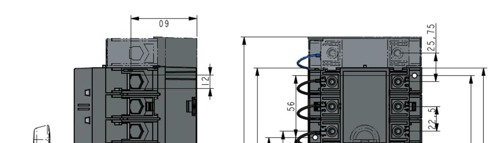


16 6.2. Installation dimensions Figure 16 Dimensions 13


17 7. Optional accessories 7.1 Bridging bars OTM32~125F2C20D OTM32~125F3C20D OTM32~125F4C20D OMZC03 OMZC04 6 Nm 17 Number of conductors permitted to be clamped on the terminal 2, Wire specification: 10-70mm 2, 8-00AWG Figure 17 Bridging bars 14


18 7.2 Terminal shrouds,1 OTS125T3,2 OTS125T1,3,4 7.3 Auxiliary contact blocks Figure 18 Terminal shrounds OA7G10/OA1G AWG OA2G Nm I OA7G10 OA1G01 Contact type NO NC I O II II OA1G10 OA8G01 Contact type NO NC I O II OA2G11 has two layers to provide a maximum of 4 NO + 4 NC auxiliary contacts. OA2G11 Only suitable for 3- pole products Figure 19 Auxiliary contact blocks 15
19 8. Maintenance and common troubleshooting 8.1 Maintenance To ensure the operation reliability of switches, regular switching tests should be performed (once every 3 months) to confirm normal function. 8.2 Common troubleshooting No. Fault Description Fault Analysis Troubleshooting Method 1 Power supply functioning normally, but LED not ON Control unit power supply terminal not connected with switch wiring terminal Check and connect the switch wiring terminal 2 Power supply LED functioning normally but "AUTO" LED OFF, or no response with AUTO button pressed 3 Transition failure in case of faulty power supply 4 EMRG OFF function failure 5 AUTO LED blinking with all other LEDs OFF No response from buttons Handle not pulled out or electrical padlock not removed 1. Switch not operating in "AUTO" mode 2. Both power supplies malfunctioning 1. Check if the EMRG OFF signal is 24V DC 2. Too short duration of EMRG OFF signal DIP switch for poles number of power supply set to 00 6 I or II LED blinking Execution rejected during switching operation, thus expected result not achieved Table 5 Troubleshooting Pull out the handle or remove the padlock, and then press the "AUTO" button Make sure the switch is working in "AUTO" mode; check and make sure both power supplies are not malfunctioning simultaneously; Correctly switch on the EMRG OFF signal, which should only be 24V DC with the duration 1 s Check if the DIP switch setup matches the phase number of switch power supply. Manually set the switch to Position O, and press the AUTO button to reset 16

20 9. Appendix 9.1 Wiring diagram Figure 20 Wiring Diagram 17
21 v Read through this instruction book carefully before working on the switch, and keep this instruction book to hand for later reference v The images provided in this instruction book are for illustration purposes only and may not match the actual product exactly v This instruction book is subject to change for product updates without prior notice ABB Xinhui Low Voltage Switchgear Company Limited Jinguzhou Industrial Zone, Xinhui District, Jiangmen City, Guangdong Province, PRC Postal code: Tel: Fax: THT303803P4001-D
Automatic Transfer Switch OTM_C20D
 v Read through this instruction carefully before working on the switch, and keep this instruction for later reference v The images provided in this instruction book are for illustration purposes only and
34OTM_F_C rev. F / 1SCC303009M0206. Motorized change-over switches OTM_F_C Installation and operating instructions
 4_F_C rev. F / SCC0009M006 Motorized change-over switches _F_C nstallation and operating instructions Contents Contents Mounting and dimensional drawings... 4 Mounting positions... 5 Control circuit...
PGR-4700 MANUAL SENSITIVE GROUND-FAULT RELAY
 Tel: +1-800-832-3873 E-mail: techline@littelfuse.com www.littelfuse.com/pgr-4700 PGR-4700 MANUAL SENSITIVE GROUND-FAULT RELAY REVISION 2-B-032218 Copyright 2018 by Littelfuse, Inc. All rights reserved.
SERIES 230 A2ADTL Transfer Switch User Manual
 SERIES 230 A2ADTL Transfer Switch User Manual Version V1.1 Revision Date Jan 12 th, 2018 BOM Code 31013293 ASCO Power Technologies provides customers with technical support. Users may contact the nearest
PGR-6101 MANUAL GROUND-FAULT & INSULATION MONITOR
 Tel: +1-800-832-3873 E-mail: techline@littelfuse.com www.littelfuse.com PGR-6101 MANUAL GROUND-FAULT & INSULATION MONITOR Revision 0-C-041918 Copyright 2018 by Littelfuse, Inc. All rights reserved. Document
PGR-3200 MANUAL INSULATION MONITOR
 Tel: +1-800-832-3873 E-mail: techline@littelfuse.com www.littelfuse.com PGR-3200 MANUAL INSULATION MONITOR REVISION 3-E-040918 Copyright 2018 by Littelfuse, Inc. All rights reserved. Document Number: PM-1025-EN
Safety Switching Devices SNO 4003K. Basic device for Emergency-Stop and Safety Gate Applications PI E
 EN 60204-1 Stop category 0 EN 954-1 Safety category 4 Basic device to EN 60204-1 and EN 954-1 single E-stop monitoring. Manual or automatic start Application up to safety category 2 and stop category 0
Motorized switch-disconnectors OTM_F_. Installation instruction 34OTM_F_ / 1SCC303010M0202
 Motorized switch-disconnectors _F_ Installation instruction 4_F_ / SCC000M00 Contents Installation instruction, _F_ Contents Mounting and dimensional drawings... 4 Mounting positions... 5 Control circuit...
PGR-6100 MANUAL GROUND-FAULT & INSULATION MONITOR
 Tel: +1-800-832-3873 E-mail: techline@littelfuse.com www.littelfuse.com/pgr-6100 PGR-6100 MANUAL GROUND-FAULT & INSULATION MONITOR Revision 2-C-050818 Copyright 2018 Littelfuse All rights reserved. Document
MG24434 Supplementary Protector SUPPLEMENTARY PROTECTOR, 240VAC, 16A, CIRCUIT BREAKER TYPE: STANDARD
 United States MG24434 Supplementary Protector SUPPLEMENTARY PROTECTOR, 240VAC, 16A, CIRCUIT BREAKER TYPE: STANDARD Product Information Features and Specifications For Use With: OEM Panels Approvals: UL
Datasheet - SLB 200-C04-1R
 14.02.2013-17:06:30h Datasheet - SLB 200-C04-1R Safety light barriers / Safety monitoring modules to monitor safety light barriers / SLB 200-C Up to 2 light barrier pairs SLB 200 can be connected 1 safety
SERIES 230 Automatic Transfer Switch C1000 Intelligent Controller User Manual
 SERIES 230 Automatic Transfer Switch C1000 Intelligent Controller User Manual Document Version V2.3 Archive Date Jan 12 th, 2018 BOM Code 31012665 ASCO Power Technologies provides customers with technical
Automatic transfer switches. TruONE ATS, OX_ _. 34OX_ rev. A / 1SCC303011M0201. Automatic transfer switches
 INSTALLATION AND OPERATING INSTRUCTION Automatic transfer switches TruONE ATS, OX_ 30...600_ Automatic transfer switches 34OX_30-600 rev. A / SCC3030M020 Receiving, handling and storage Warning HAZARD
SERIES 230 C2ADTL Transfer Switch User Manual
 SERIES 230 C2ADTL Transfer Switch User Manual Version V1.2 Revision Date Feb 25, 2013 BOM Code 31012691 Emerson Network Power provides customers with technical support. Users may contact the nearest Emerson
PGR-4300 MANUAL GENERATOR GROUND-FAULT RELAY
 Tel: +1-800-832-3873 E-mail: techline@littelfuse.com www.littelfuse.com PGR-4300 MANUAL GENERATOR GROUND-FAULT RELAY REVISION 3-B-041318 Copyright 2018 by Littelfuse, Inc. All rights reserved. Document
60103 Circuit Breaker
 6003 Circuit Breaker United States MINIATURE CIRCUIT BREAKER, 20/240VAC, 2A, CIRCUIT BREAKER TYPE: STANDARD Image not available Product Information Features and Specifications Circuit Breaker Type: Standard
29 $ Manual Motor Starters FREESHIPPING. MOTOR CONTROLS 25. Features: MMS-32H Frame. MMS-63H Frame.
 www.factorymation.com/motorcontrols MOTOR CONTROLS 25 Manual Motor Starters High interrupt capacity Din rail and surface mounting Lockable handle (OFF position) IP20 finger safe terminals Class 10 thermal
Nemo SX - Multifunction control module
 Via Travaglia 7, 20094 Corsico (MI) - Italia Tel. +39 0244878.1 - Fax +39 024503448 Contents Pages 1. Description - Use... 1 2. Range... 1 3. Overall dimensions... 1 4. Preparation - Connection... 1 5.
Mini Contactors & Overloads
 108 Mini s & Overloads GMC-12M Surface or DIN rail mountable UL508 compliant 1/ to 7-1/ 50/60Hz AC and DC versions available Direct-mounting overloads RoHS compliant Auxiliary contacts standard (1 N.0.)
ict contactors EN 61095, IEC 1095 Interference
 ict contactors DB23399 DB669 DB06604 Country approval pictograms EN 6095, IEC 095 ict contactors are available in two versions: b Contactors without manually-operated b Contactors with manually-operated.
SE-135 MANUAL GROUND-FAULT GROUND-CHECK MONITOR
 SE-135 MANUAL GROUND-FAULT GROUND-CHECK MONITOR AUGUST 14, 2001 REVISION 1 Publication: SE-135-M Document: S95-C135-00000 Printed in Canada. Copyright 2001 by Startco Engineering Ltd. All rights reserved.
Motor protection relays
 Thermal overload relays for currents between 0.09 and 420A Electronic thermal overload relays for currents between 0.4 and A Electronic thermal overload relays with selectable tripping class: 5--20-30
Single-phase ( V) voltage monitoring: Undervoltage Overvoltage Window mode (overvoltage + undervoltage) Voltage fault memory selectable
 voltage monitoring: Undervoltage Overvoltage Window mode (overvoltage + undervoltage) Voltage fault memory selectable") 70 Series - Line monitoring relay 70 Features 70.11 70.31 70.41 Electronic voltage monitoring relays for single and three-phase applications Multifunctional types, providing the flexibility of monitoring
70 Series - Line monitoring relay 70 Features 70.11 70.31 70.41 Electronic voltage monitoring relays for single and three-phase applications Multifunctional types, providing the flexibility of monitoring
voltage monitor relays
 voltage monitor relays catalog of products PRODUCT SUMMARY voltage monitor relays Voltage Monitor Relays monitor either AC single phase (50-60Hz) or DC voltages to protect equipment against voltage fault
VEO. V2UF230V10 Art.Nr.: TECHNICAL DATA
 Continous voltage monitoring Mains fluctuation detection Detects voltage drop / short interruptions of at least 10ms Prevents undefined states in switching and control systems Generates reset pulse after
ic60n RCBO 30 ma IEC , IEC , AS/NZS
 ic60n RCBO 30 ma DB405571 Country approval pictograms IEC 61009-1, IEC 61009-2-2, AS/NZS 61009.1 PB110075-70 b The single-phase ic60n RCBO s self-contained residual current device provides protection of
SAFETY RELAY YRB-4EML-31S MAIN FEATURES
 SAFETY RELAY TYPE 4 SAFETY PROTECTION DEVICE FOR SAFETY LIGHT CURTAINS/BARRIERS MAIN FEATURES For safety light curtains and access control barriers, emergency stop, door switch Safety Integrity Level (SIL)
Voltage Dip-Proofing Inverter
 Voltage Dip-Proofing Inverter DPI54S / 54L Series Models 120V & 208/230 50/60Hz Contents: Introduction...3 Theory of operation...3 Specifications...5 Up-time considerations...6 Installation Guide...7 Test
NF44E-.. / NFZ44E-.. Contactor Relays AC / DC Operated - with Screw Terminals
 Technical Datasheet 1SBC1010D0201 28/03/11 NFE-.. / NFZE-.. Contactor Relays AC / DC Operated - with Screw Terminals NF(Z) contactor relays are used for switching auxiliary and control circuits. NF(Z)
CurrentWatch Current Sensors. EGF Series Ground Fault Sensors. Ground Fault Sensors with Solid-State or Mechanical Relay Outputs.
 CurrentWatch Current Sensors Ground Fault Sensors with Solid-State or Mechanical Relay s 1 Contents Overview.................... 1 Model Selection, Switches...... 2 Model Selection, Accessories... 3 Wiring
FL MC 2000T. Fiber optic converter for 10/100Base-Tx to single- or multi-mode fiberglass with SC-duplex and ST connections. Data sheet 3379_en_B
 Fiber optic converter for 10/100Base-Tx to single- or multi-mode fiberglass with SC-duplex and ST connections Data sheet 3379_en_B 1 Description PHOENIX CONTACT 2015-07-14 2 Features Media converters provide
EMS CX 3 - State and control module for Latching relays and Contactors
 LEGRAND - BP30076 87045 LIMOGES CEDEX FRANCE Telephone: 05 55 06 87 87 Fax: 05 55 06 88 88 Contents Pages 1. Description - Use... 1 2. Range... 1 3. Overall dimensions... 1 4. Preparation - Connection...
Ordering Key. Type Rated Operational Rated operational Control Voltage Uc Options
 otor Controllers AC Semiconductor otor Controller Type RSHR 3-Phase Soft starting and stopping of 3-phase squirrel cage motors Control of all 3 phases In Line or In Delta motor connection Low inrush and
Monitoring technique. VARIMETER Voltage relay MK 9064N, MH 9064
 Monitoring technique VARIMETER Voltage relay MK 9064N, MH 9064 0269462 Your Advantages Preventive maintenance For better productivity Quicker fault locating Precise and reliable Min-, Max. value or window
Allen-Bradley 1492-RCDA4A40
 Dual terminals provide wiring/bus bar flexibility and clamp from both sides to improve connection reliability Suitable for DIN Rail mounting Approval marks are easily visible on dome Terminal design helps
Motor Controllers AC Semiconductor Motor Controller Type RSHR MIDI
 otor Controllers AC Semiconductor otor Controller Type RSHR IDI Soft starting and stopping of 3-phase induction squirrel cage motors 2-phase control with integral bypassing of semiconductors Low inrush
PSR-SCP- 24DC/URM4/4X1/2X2/B PSR-SPP- 24DC/URM4/4X1/2X2/B
 Safety Relay as a Contact Extension Block INTERFACE Data Sheet PHOENIX CONTACT - 05/2006 Description The PSR-...- 24DC/URM4/4X1/2X2/B safety relay can be used as a contact extension block in safety circuits
9212i INSTALLATION. Stand-Alone Keypad. Instructions
 INSTALLATION 9212i Stand-Alone Keypad Instructions Features: 4 Independent Outputs 4 Independent Timers All Outputs Assignable by Code On board 5 Amp Form C Relay 120 Users Remote Triggering Input Keypad
Voltage Dip-Proofing Inverter
 Voltage Dip-Proofing Inverter DPI53S / 54L Series Models 120V & 208/230 50/60Hz LEADERS IN VOLTAGE DIP-PROOFING Contents: Introduction...3 Theory of operation...3 Specifications...5 Up-time considerations...6
Motor Controllers AC Semiconductor Motor Controller Type RSHR MIDI
 otor Controllers AC Semiconductor otor Controller Type RSHR IDI Soft starting and stopping of 3-phase induction squirrel cage motors 2-phase control with integral bypassing of semiconductors Low inrush
Rated operational Control Voltage Uc Supply Voltage Connection Rated operational current 40 C voltage Ue Us 25A AC-53a 32A AC-53a
 otor Controllers AC Semiconductor otor Controller Type RSHR 3-Phase Soft starting and stopping of 3-phase squirrel cage motors Control of all 3 phases In Line or In Delta motor connection Low inrush and
SR2A201BD compact smart relay Zelio Logic - 20 I O - 24 V DC - no clock - display
 Characteristics compact smart relay Zelio Logic - 20 I O - 24 V DC - no clock - display Main Range of product Product or component type Complementary Local display Number or control scheme lines Cycle
EMS CX 3 - State and control module for Latching relays and Contactors
 87045 LIMOGES Cedex Telephone : 05 55 06 87 87 Fax: 05 55 06 88 88 EMS CX 3 - State and control module Contents Pages 1. Description - Use... 1 2. Range... 1 3. Overall dimensions... 1 4. Preparation -
PSR-SCP- 24DC/SDC4/2X1/B PSR-SPP- 24DC/SDC4/2X1/B
 PSR-SCP- 24DC/SDC4/2X1/B PSR-SPP- 24DC/SDC4/2X1/B Safety Relay for Emergency Stop and Safety Door Circuits INTERFACE Data Sheet 102858_02_en PHOENIX CONTACT - 12/2006 Description The PSR-...- 24DC/SDC4/2X1/B
VMD420-DM Voltage and frequency monitor
 EN Manual VMD420-DM Voltage and frequency monitor for monitoring of 3(N)AC systems up to 0 500 V for undervoltage and overvoltage and under and overfrequency Software version: D238 V2.2x VMD420-DM_D00227_01_M_XXEN/07.2015
Section 4 Ground-Fault Protection Devices
 Multi 9 System Catalog Section 4Ground-Fault Protection Devices Section 4Ground-Fault Protection Devices Selection Table The Multi 9 System includes one UL Listed and three IEC rated product families that
PSR UC/ESAM4/3X1/1X2/B
 Safety relay for emergency stop and safety door monitoring Data sheet 105318_en_02 PHOENIX CONTACT 2014-06-13 1 Description The safety relay can be used in safety circuits according to EN 60240-1 and IEC
Switching relay CT-IRS with 1, 2 or 3 c/o contacts Data sheet
 1SVR 430 221 F7300 2 1 3 Characteristics Switching relay ON-delay approx. 10 ms 1, 2 or 3 c/o contacts Switching relay with gold-plated contacts Width 22.5 mm Approvals e f GOST CCC CT-IRS 1 U/R: green
Electronic timer CT-VBS OFF-delayed without auxiliary voltage, for DC contactors Data sheet
 Characteristics Single-function OFF-delay timer for DC contactors, without auxiliary voltage Width.5 mm CDC 5 6 F Approvals a culus f CCC CT-BS Circuit diagram Marker label Marks g c CE C-Tick Order data
RE17LAMW on-delay timing relay - 1 s..100 h V AC/ DC - solid state output
 Characteristics on-delay timing relay - 1 s..100 h - 24..240 V AC/ DC - solid state output Main Range of product Product or component type Discrete output type Width Component name Time delay type Time
Surge Protection Devices Ex9UE2
 Surge Protection Devices Ex9UE2 Surge Protection Devices Type 2 (Class II, T2, C) Tested according to EN 61643-11 Maximum continuous operational voltage U c from 275 V up to 440 V AC Versions with 1+0,
Datasheet - SRB 402EM-24V
 Print - Create PDF - Create EXCEL file 20.04.2011-18:31:35h Datasheet - SRB 402EM-24V Output expanders / SRB 402EM Expander module for contact expansion 4 safety contacts, STOP 0 2 Signalling outputs (Minor
RE17LCBM off-delay timing relay - control - 1 s..100 h V - solid state output
 Characteristics off-delay timing relay - control - 1 s..100 h - 24..240 V - solid state output Main Range of product Product or component type Discrete output type Width Component name Time delay type
Issued February DATA SHEET 5SX2 MCB. Based on Siemens Industrial Control Catalog
 Issued February 2011 DATA SHEET 5SX2 MCB Based on Siemens Industrial Control Catalog General Data Trip characteristics Tripping characteristics acc. to EN 60 898 Tripping characteristic A, -5 Type A characteristic
BNS SERIES - COMPATIBLE SERIES AES SAFETY CONTROLLERS SELECTION CHART AVAILABLE STANDARD MODELS
 BNS SERIES - COMPATIBLE SERIES AES SAFETY CONTROLLERS SELECTION CHART AVAILABLE STANDARD MODELS Safety Controller Suitable for use with Coded-Magnet Sensor Part Numbers below BNS250... BNS33... BNS303...
ST 200 M data sheet System pro M compact miniature circuit breakers for supplementary protection acc. to UL 1077
 MINIATURE CIRCUIT BREAKERS ST 200 M data sheet System pro M compact miniature circuit breakers for supplementary protection acc. to UL 1077 The ST 200 M miniature circuit breaker provides supplementary
PSR-PC50. SIL 3 coupling relay for safety-related switch on. Data sheet. 1 Description
 SIL 3 coupling relay for safety-related switch on Data sheet 105818_en_01 PHOENIX CONTACT 2014-08-18 1 Description The PSR-PC50 SIL coupling relay can be used for power adaptation and electrical isolation
ATS Automatic transfer switches Advanced version
 87045 LIMOGES Cedex Phone :+33 05 55 06 87 87 Fax :+33 05 55 06 88 88 ATS CONTENTS PAGES 1. USE 1 2. RANGE 1 3. DIMENSIONS 1 4. ELECTRICAL AND MECHANICAL CHARACTERISTICS 2 5. CONFORMITY 4 6. EQUIPMENTS
Control elements. Fine adjustment. Status indication. 24 V DC typ. 0,25 W / 0,25 VA. 24 V DC typ. 0,03 W / 0,09 VA. 0,15 3 s. 0,5 10 h.
 On-Delay 10 time ranges Supply voltage 24-240V AC/DC 1 change-over contact Width 22,5mm Control elements Fine adjustment Setting of time range Status indication LED U/t: Supply voltage LED R: Relay status
LINETRAXX RCMS150. Residual current monitor type B with integrated measuring current transformers for earthed AC/DC systems (TN and TT systems)
") LINETRAXX RCMS150 Residual current monitor type B with integrated measuring current transformers for earthed AC/DC systems (TN and TT systems) RCMS150_D00259_00_D_XXEN/09.2016 LINETRAXX RCMS150 Residual
LINETRAXX RCMS150 Residual current monitor type B with integrated measuring current transformers for earthed AC/DC systems (TN and TT systems) RCMS150_D00259_00_D_XXEN/09.2016 LINETRAXX RCMS150 Residual
OVERLOAD RELAYS POWER & ACTUATION PROVEN. series
 POWER & ACTUATION OVERLOAD RELAYS series Need reliable, accurate overload and phase-loss protection for your motors? c3controls Series Bimetallic Overload Relays provide unmatched protection and can be
02/11/2015
 DIN Rail Mount 35 mm HSV Part number 84874320 Control of overspeed, underspeed, operating rate, stopping Measurement via discrete sensors - 3-wire PNP or NPN, Namur, voltage 0-30V or volt-free contact
70 SERIES. Line monitoring relay
 70 SRIS 70 SRIS lectronic voltage monitoring relays for single and three-phase applications Multifunctional types, providing the flexibility of monitoring Undervoltage, Overvoltage, Window Mode, Phase
PCT2000. User Manual. Precision current transducer 2000 A
 PCT2000 User Manual PCT2000 Precision current transducer 2000 A User Manual Status: November 6, 2018 Copyright 2018 ZES ZIMMER Electronic Systems GmbH Pfeiffstraße 12 61440 Oberursel (Taunus), Germany
PACSystems RX3i IC695PSA140
 GFK2399A October 2005 PACSystems RX3i IC695PSA140 120/240VAC or 125VC, 40 Watts IC695PSA140 is a multipurpose 40Watt supply that operates from an input voltage source in the range of 85 to 264 VAC or 100
References. References. Rating (A) Référence
 Référence") DIRECT OPERATION T O O R D E R EXTERNAL OPERATION picto_080_c_1_gb Switch body Direct Switch body + handle + Shaft + + OTHER ACCESSORIES External handle acces_128_a_1_cat acces_129_a_1_cat Direct handle
DIRECT OPERATION T O O R D E R EXTERNAL OPERATION picto_080_c_1_gb Switch body Direct Switch body + handle + Shaft + + OTHER ACCESSORIES External handle acces_128_a_1_cat acces_129_a_1_cat Direct handle
Electronic timer CT-AHS OFF-delayed with 2 c/o contacts Data sheet
 2CDC 251 113 F0004 CT-AHS 1 7 2 6 5 4 8 3 1 10 selectable time ranges, from 0.05 s to 300 h 2 Potentiometer with direct reading scale for the fine adjustment of the time delay 3 Sliding switch to set the
TeSys IEC Contactors and Overload Relays
 TeSys IEC Contactors and Overload Relays Making High-Fault Short-Circuit Current Ratings Simple Schneider Electric is an industry leader in IEC contactors and overload relays, and is recognized as the
Voltage monitoring relays CM-ESS.1 For single-phase AC/DC voltages
 Data sheet Voltage monitoring relays CM-ESS.1 For single-phase AC/DC voltages The CM-ESS.1 is an electronic voltage monitoring relay that provides reliable monitoring of voltages as well as detection of
SLIMCON-6 24V DC POWERED ISOLATING SIGNAL CONVERTER
 SLIMCON-6 24V DC POWERED ISOLATING SIGNAL CONVERTER Whilst every effort has been taken to ensure the accuracy of this document, we accept no responsibility for damage, injury, loss or expense resulting
RM35UB3. Product data sheet Characteristics. voltage control relay RM35-U - range V AC. Main. Complementary
 Characteristics voltage control relay RM35-U - range 194..528 V AC Main Range of product Product or component type Relay type Product specific application Relay name Relay monitored parameters Time delay
PROGRAMMABLE MULTI-RANGE REPEAT CYCLE & DELAYED INTERVAL
 PROGRAMMABLE MULTI-RANGE REPEAT CYCLE & DELAYED INTERVAL TR-6 Series Time Ranger tm INPUT VOLTAGE PRODUCT WIRING/ FUNCTION 50/60Hz. NUMBER SOCKET time delay relays plug-in Each unit has 16 timing ranges
PGR-2601 MANUAL DC GROUND-FAULT RELAY
 POWR-GARD Ungrounded DC System PGR-2601 SERIES DC Ground-Fault Relay PGR-2601 MANUAL DC GROUND-FAULT RELAY AUGUST 31, 2009 REVISION 1 POWR-GARD DC GROUND-FAULT RELAY PWR TRIP 5 4 3 2 6 - BUS 8 10 15 20
VEO. V2PF480Y/277VSY01 Art.Nr.: V2PF480Y/277VSY01P Art.Nr.: TECHNICAL DATA
 Monitoring of phase sequence and phase loss Monitoring of asymmetry Supply voltage 208-480 V AC Supply circuit = measuring circuit 1 change-over contact Width 22,5 mm Control elements Asymmetry Status
PSR-MS60. Safety relay for emergency stop, safety door and light grid monitoring. Data sheet. 1 Description
 SILCL IEC 62061 Safety relay for emergency stop, safety door and light grid monitoring Data sheet 106171_en_01 PHOENIX CONTACT 2015-05-19 1 Description Intended Use The PSR-MS60 safety relay can be used
Electronic timer CT-ERS.12 ON-delayed with 1 c/o (SPDT) contact
 contact") Data sheet Electronic timer CT-ERS.12 ON-delayed with 1 c/o (SPDT) contact The CT-ERS.12 is an electronic timer from the CT-S range with ON-delay and 10 time ranges. All electronic timers from the CT-S
Data sheet Electronic timer CT-ERS.12 ON-delayed with 1 c/o (SPDT) contact The CT-ERS.12 is an electronic timer from the CT-S range with ON-delay and 10 time ranges. All electronic timers from the CT-S
RM35TF V AC
 Characteristics multifunction phase control relay RM35-T - range 194..528 V AC Main Range of product Product or component type Relay type Product specific application Relay name Relay monitored parameters
Datasheet SRB301ST 24V (V.2)
") 26.10.2016 05:03:31h Datasheet SRB301ST 24V (V.2) Guard door monitors and Safety control modules for Emergency Stop applications / General Purpose safety controllers (Series PROTECT SRB) / SRB301ST Suitable
26.10.2016 05:03:31h Datasheet SRB301ST 24V (V.2) Guard door monitors and Safety control modules for Emergency Stop applications / General Purpose safety controllers (Series PROTECT SRB) / SRB301ST Suitable
24973 Circuit Breaker MINIATURE CIRCUIT BREAKER, 440VAC, 10A, CIRCUIT BREAKER TYPE: STANDARD
 United States 24973 Circuit Breaker MINIATURE CIRCUIT BREAKER, 440VAC, 10A, CIRCUIT BREAKER TYPE: STANDARD Image not available Product Information Features and Specifications Approvals: IEC 60947-2 Rated
RM17UB3. Product data sheet Characteristics. voltage control relay RM17-U - range V AC. Main. Complementary
 Characteristics voltage control relay RM17-U - range 183..528 V AC Main Range of product Product or component type Relay type Product specific application Relay name Relay monitored parameters Time delay
Solid-state Timer. Ordering Information. Miniature Timer with Multiple Time Ranges and Multiple Operating Modes H3YN- - Accessories (Order Separately)
") Solid-state Timer Miniature Timer with Multiple Time Ranges and Multiple Operating Modes Minimizes stock. Pin configuration compatible with MY Power Relay. Standard multiple operating modes and multiple
Solid-state Timer Miniature Timer with Multiple Time Ranges and Multiple Operating Modes Minimizes stock. Pin configuration compatible with MY Power Relay. Standard multiple operating modes and multiple
MSR178DP. Description. Features. Specifications
 MSR178DP Description The MSR178DP is a multi-function time-delay relay for use in safety circuits. It can be configured by the user to perform on-delay, offdelay or single-pulse modes. It is used for applications
FL MC 2000E (SM40) LC
 LC") IEC 61850 fiber optic converter with LC fiber optic connection (1310 nm) to convert 100Base-Tx to single- or multi-mode fiber glass Data sheet 3205_en_C 1 Description PHOENIX CONTACT 2014-04-04 2 Features
IEC 61850 fiber optic converter with LC fiber optic connection (1310 nm) to convert 100Base-Tx to single- or multi-mode fiber glass Data sheet 3205_en_C 1 Description PHOENIX CONTACT 2014-04-04 2 Features
RM17UAS. Product datasheet Characteristics. voltage control relay RM17-U - range V DC. Main. Complementary. Price* : 70.
 Characteristics voltage control relay RM17-U - range 9..15 V DC Price* : 70.64 GBP Main Range of product Product or component type Relay type Product specific application Relay name Relay monitored parameters
High Impedance Protection Relay SPAE010, SPAE011. Product Guide
 SPAE010, SPAE011 SPAE010, SPAE011 1MRS750383-MBG Issued: April 1999 Status: Updated Version: D/21.03.2006 Data subject to change without notice Features High impedance type differential current earth-fault
VEO. V2ZS V AC/DC Art.Nr.: V2ZS20P V AC/DC Art.Nr.: TECHNICAL DATA
 4 time ranges 4 transition times Supply voltage 12-240V AC/DC 2 normally open contacts Width 22,5 mm Control elements Fine adjustment star contactor Setting of time range star contactor Transit time Status
Electronic timer CT-ARS.21 OFF-delayed without auxiliary voltage with 2 c/o (SPDT) contacts
 contacts") Data sheet Electronic timer CT-ARS.21 OFF-delayed without auxiliary voltage with 2 c/o (SPDT) contacts The CT-ARS.21 is an electronic timer from the CT-S range with true OFF-delay. It provides 7 time ranges
Data sheet Electronic timer CT-ARS.21 OFF-delayed without auxiliary voltage with 2 c/o (SPDT) contacts The CT-ARS.21 is an electronic timer from the CT-S range with true OFF-delay. It provides 7 time ranges
SECTION 16 LED DIAGNOSTIC FEATURES: EXPANSION UNITS: SCR-31P-i. SCR-73-i. SEU-31-i. SCR-31-42TD-i. SEU-31TD-i
 SECTION 16 VIPER Safety Relays Type: SCR-i (with added diagnostics) SAFETY RELAY FUNCTION: IDEM s VIPER SCR-i range of Safety Relays have been designed in accordance with EN60204-1 for safety circuits
SR2B201FU compact smart relay Zelio Logic - 20 I O V AC - clock - display
 Characteristics compact smart relay Zelio Logic - 20 I O - 100..240 V AC - clock - display Main Range of product Product or component type Complementary Local display Number or control scheme lines Cycle
Datasheet - SRB 301LC/B-24V
 27.01.2016-00:27:16h Datasheet - SRB 301LC/B-24V Guard door monitors and Safety control modules for Emergency Stop applications / General Purpose safety controllers (Series PROTECT SRB) / SRB 301LC/B Fit
Serial Data DIN Fiber Link System
 USER GUIDE RLH Industries, Inc. The leader in rugged fiber optic technology. U-120 2017A-0420 DIN Fiber Link System COMPACT, RUGGED & TEMPERATURE HARDENED Introduction The DIN Fiber Link system transports
3 Pole Contactors with AC operating coils
 1 3 Pole Contactors with AC operating coils Characteristics General Characteristics Switching Current 9A ~ Rated insulation voltage (Ui) (Conforming to IEC 158-1) V 750 IEC 60947-4 V 1000 Conforming to
Approved Standards. Motor Protection Circuit Breaker (MPCB) J7MN. MPCB system (motor protection CLASS 10) Auxiliary contact modules.
 J7MN. MPCB system (motor protection CLASS 10) Auxiliary contact modules.") Motor Protection Circuit Breaker (MPCB) J7MN MPCB system (motor protection CLSS 0) Rotary and switch types Rated operational current = 2, 25, 50 and 00 Switching capacity up to 2.5 = 00 k/400 V Fixed short-circuit
Motor Protection Circuit Breaker (MPCB) J7MN MPCB system (motor protection CLSS 0) Rotary and switch types Rated operational current = 2, 25, 50 and 00 Switching capacity up to 2.5 = 00 k/400 V Fixed short-circuit
MSR Level Control Relay Module Operating Instructions for Level Control Relay Module Model: MSR
 Operating Instructions for Level Control Relay Module Model: MSR MSR Operation Instructions Rev. Apr 07 Page 1/8 1. Note Please read and take note of these operating instructions before unpacking and commissioning.
RE17LAMW on-delay timing relay - 1 s..100 h V AC/DC - solid state output
 Characteristics on-delay timing relay - 1 s..100 h - 24..240 V AC/DC - solid state output Complementary Control type Voltage range Main Range of product Product or component type Discrete output type Width
Safety Relay F 121 Emergency-Stop Relay, Safety Gate Monitor
 Safety Relay F 121 Emergency-Stop Relay, Safety Gate Monitor Features M Safety-category 4 acc. to DIN EN954-1 M Stop-category 0 M Crossfault monitoring M Monitored start (On-switch) or automatic start
Solid-state Timer. Ordering Information. Ultra-slim Timer for G2R Relay Socket. H3RN-jj. Accessories (Order Separately) Connecting Socket
 Connecting Socket") Solid-state Timer Ultra-slim Timer for G2R Relay Socket Pin configuration compatible with G2R Relay and mounts to the P2R/P2RF Socket. Standard multiple time ranges and multiple operating modes. Conforms
Solid-state Timer Ultra-slim Timer for G2R Relay Socket Pin configuration compatible with G2R Relay and mounts to the P2R/P2RF Socket. Standard multiple time ranges and multiple operating modes. Conforms
MULTI 9 System Catalog UL Recognized NC100H Supplementary Protectors
 B Curve NC100H Supplementary Protectors Rating 1P 2P 3P 4P 80 MG27164 MG27175 MG27186 MG27197 MULTI 9 System Catalog UL Recognized NC100H Supplementary Protectors C Curve NC100H Supplementary Protectors
Slim Relay G2RV. Model Number Structure. Ordering Information. Model Number Legend. List of Models. Relay and Socket Combinations
 Slim Relay G2RV The World's First Industrial Slim Relay Large plug-in terminals for reliable connection. LED indicator and mechanical flag to check operation. Transparent housing enables checking relay
Electronic timer CT-ERS.12 ON-delayed with 1 c/o contact Data sheet
 2CDC 251 056 F0t07 Features Rated control supply voltage 24-48 V DC, 24-240 V AC Single-function ON-delay timer One device includes 10 time ranges (0.05 s - 300 h) 1 c/o contact 2 LEDs for status indication