I. Individual control system
|
|
|
- Blaze Todd
- 6 years ago
- Views:
Transcription
1 Control Systems
2 I. Individual control system 1 2 Wireless signal receiver kit MRK-A00 1) Features ) Wiring Wireless remote controller 4. MWR-VH02 1) Features ) Description of parts ) Function keys ) Option switches ) Error code display MR-DH00 1) Features ) Description of parts ) Additional function Installation 1) MWR-WH00/WE10/SH ) MWR-VH ) Installation caution Wired remote controller 1. MWR-WH00 1) Features ) Description of parts ) Additional function ) Option switches ) User setting mode ) Service mode ) Error display ) Built-in temperature sensor of wired remote controller day scheduler MWR-BS00 1) Features ) Description of parts ) Additional function ) Installation ) Connection examples MWR-WE10 1) Features ) Description of parts ) User setting mode ) Service mode ) Error display ) Wireless remote controller built-in temperature sensor ) Energy saving operation mode MWR-SH00 1) Features ) Description of parts ) Additional function
3 II. Centralized control systems 1 2 Interface module 1. MIM-B13D 1) Features ) Product specification ) Description of parts ) Compatible models ) Connecting with upper level controller ) Operation display MIM-B13E 1) Features ) Product specification ) Description of parts ) Compatible models ) Connecting with upper level controller ) Operation display Centralized controller 3 4 Function controller MCM-A100 1) Features ) Specification ) Description of parts ) Connection with centralized controller ) Address & option switch ) Initial LCD display ) Connection diagram ) Precaution on wiring with the centralized controller ) Error display Operation mode selection switch MCM-C200 1) Features ) Installation ) Control example INDIVIDUAL CONTROL SYSTEM CENTRALIZED CONTROL SYSTEM INTEGRATED MANAGEMENT SYSTEM POWER CISTRIBUTION SYSTEM MCM-A202D 1) Features ) Specification ) Description of parts ) Wiring ) Address & option switch ) Various LED display ) Compatibility with interface module ) Operation mode selection switch.. 75 EXTERNAL CONTACT CONTROL SYSTEM BUILDING MANAGEMENT SYSTEM 3
4 III. Integrated management system 1 DMS2 1 2 MIM-D00A 1) Features ) Product specification ) Connection diagram ) Compatible devices ) Description of parts ) Connection ) Wiring distance ) Accessing DMS ) Additional function S-NET3 MST-P3P 1) Features ) PC specification ) System connection ) Function ) Detail function description IV. Power distribution system Electricity meter interface module MIM-B16 1) Features ) Display and buttons ) Connectors ) Address & option switches ) Specifications on electricity meter ) Installation ) Wiring ) Address assignment ) MIM-B16 menu structure ) Setting parameters on DMS2 (MIM-D00A) ) Error S-NET mini MST-S3W 1) Features ) Main panel ) Connectors ) Option switches ) Flexible communication connection ) Menu ) Upgrading ) Hardware test ) Data backup
5 V. External contact control system 1 Key-tag interface module 2 LonWork Gateway INDIVIDUAL CONTROL SYSTEM 1 MIM-B02 1) Features ) Description of parts ) Additional functions ) Installation External contact interface module MIM-B14 1) Features ) Description of parts ) Installation ) Control VI. Building management system LonWork interface module MIM-B07 1) Features ) Description of parts ) Function ) Installation MIM-B18 1) Features ) Description of parts ) Commission ) Standard program identifier (SPID) ) Specification ) Hardware specification ) Item summary ) Network variable ) Network parameter chart ) Network variable list for indoor unit/erv/ahu kit ) Detail description of network variable ) Installation BACnet Gateway MIM-B17 1) Features ) Description of parts ) Maximum number of connectable devices ) Device ID ) System structure ) Checking device ID from DMS ) Tracking & Who-is (I-Am) ) Object list ) Detail object description ) Detail description of point (DMS2 DI/DO) ) Checking BACnet communication through Wireshark ) Standard object type ) Property support specification ) Installation CENTRALIZED CONTROL SYSTEM INTEGRATED MANAGEMENT SYSTEM POWER DISTRIBUTION SYSTEM EXTERNAL CONTACT CONTROL SYSTEM BUILDING MANAGEMENT SYSTEM 5
6 DVM CONTROL SYSTEMS 6
7 I. Individual Control Systems 1 Wireless signal receiver kit Wireless remote controller Wired remote controller INDIVIDUAL CONTROL SYSTEM 4 7-day scheduler
8 Control Systems I Individual control system 1. Wireless signal receiver kit 1) Features MRK-A00 MRW-10A (Receiver wire) (Unit : mm) Wireless signal receiver Concealed wireless signal receiver Filter replacement sign Fan operation display 2) Wiring Operation Timer setting display Operation On/Off button Operation On display LED (blue) Defrost operation display LED (red) Connect one end of the receiver wire (MRW-10A) with the receiver kit (MRK-A00). Connect the other end of the receiver wire (MRW-10A) with the duct type indoor unit PCB (CN91). Indoor unit PCB Wireless signal receiver (MRK-A00) Note Wire length: 10m Receiver kit is only available for a duct type indoor unit. 2. Wireless remote controller MR-DH00 1) Features (Unit : mm) Easy and convenient operation control Operation ON/OFF control Fan speed control Operation temperature setting Filter replacement alarm reset Air swing control Simple On/Off timer Indoor unit option code setting 138 8
9 2) Description of parts - Buttons and displays INDIVIDUAL CONTROL SYSTEM, -1, -2,, -2,, is only supported and available in certain indoor units. No Name Description On/Off button Press this button to turn on/off the indoor unit. S-Plasma ion button Press this button to turn on/off the S-Plasma ion. Turbo button Press this button to cool your room quickly and powerfully. Temp + - button Press this button to increase/decrease the set temperature by 1 C. Horizontal air swing button Press this button to activate/deactivate horizontal air flow movement. -1 Beep Off button Press this button to mute the beep sounds that occurs when pressing the button. -2 Room button Press the 2nF function button and press this button to control individual indoor unit or all indoor units at once. On timer button Press the button to set the On Timer on. 2ndF button Press this button to select the function printed under the button. (Room, Blade function) Mode button Press this button to select one of the 5 operation modes. (Auto, Cool, Dry, Fan, Heat) Quiet button Press this button to select quiet mode. Vertical air swing button Press this button to activate/deactivate vertical air flow movement. (Not applicable to Duct type model) Fannnnnn button Press this button to select one of the fan speeds. (Auto, Low, Medium and High.) -1 Filter Reset button Press this button to turn off the filter indicator light. -2 Blade button Press the 2nF function button and press this button to control individual blade unit or all blades at once. good'sleep button Press this button to set the good sleep mode on. Set/Cancel button Press this button to set or cancel the On/Off Timer and good sleep mode. Off Timer button Press this button to set the Off Timer on. Operation mode indicator Indicates the operation mode. Set temperature & On/Off Basic Indicates the set temperature. set time indicator Timer setting Indicates the On/Off set time. On/Off timer indicator Indicates the On/Off timer setting. > > Room & Blade selection indicator 1) When [Beep off/room] button is pressed after pressing the 2nF button, Room indicator will be displayed with the selected indoor unit number. 2) When [Filter Reset/Blade] button is pressed after pressing the 2nF button, Blade indicator will be displayed with the selected blade number. Transmission indicator Indicates when wireless signal is received (by pressing any buttons). 2ndF indicator Indicates when 2nF button is pressed. You can select the second function (Selecting Room/ Blade) Low battery indicator Indicates the battery life. Air swing indicator Indicates when vertical or horizontal air flow movement. Fan speed indicator Indicates the fan speed settings. 9
10 Control Systems I Individual control system 2. Wireless remote controller MR-DH00 3) Additional function (1) Option code setting Remove the batteries from the remote controller. Press the Temp [+] and [-] button at the same time and insert the batteries. Set the 2 digits of option code. If you press the Fan [ ] button, you can change the first digit. If you press the Fan [ ] button, you can change the second digit. Press the [Mode] button to set the next 2 digits of option code. Input 20 digits in total. Press the button more than twice to set the indoor unit option code. (When indoor unit option code is set, a beep will sound. When the setting is incorrect, all the LED on the indoor unit panel will flicker.) > > Option code is composed with total of 24 digits including page number. From the wireless remote controller, enter the option code without page number. Setting Ex.) Option code: A A Page 0 Page 1 Page 2 Page 3 Option code input mode Fan [ Fan [ > ] Left digit ] Right digit > Press the [Mode] button to set the next 2 digits. Press the [Power] button more than two times towards the indoor unit. If you press the [Mode] button after entering first 10 digits, On timer indicator will change to Off. 10
11 3. Wired remote controller MWR-WH00 1) Features INDIVIDUAL CONTROL SYSTEM (Unit : mm) (1) Easy air conditioner control Operation ON/OFF control Operation mode, setting temperature, fan speed, air flow direction Filter replacement alert reset Single indoor unit control or multiple indoor unit group control (Able to control max. 16 indoor units.) Error display (2) Energy saving operation Upper/Lower temperature limit setting Automatic operation stop: Automatically stops the operation when it is not used for certain period of time set by user. (3) User convenience function Child lock Different button permission levels (Opertion mode, temperature setting, ON/OFF, fan speed) Built-in room temperature sensor Service mode support - Indoor unit cycle data monitoring - Indoor unit option code setting and monitoring Simple operation ON/OFF timer 11
12 Control Systems I Individual control system 3. Wired remote controller MWR-WH00 2) Description of parts - Buttons and displays Operation On/Off button Temperature setting button Fan speed button Press this button to turn on/off the indoor units Set temperature will increase by 1() each time or button is pressed Temperature range in Auto/Cool/Dry mode: 18~30 (65~-86) Temperature range in Heat mode: 16~30 (61~-86) When the button is pressed consecutively, set temperature will increased/ decrease in 0.5 second interval Temperature can not be adjusted in Fan mode Press this button to change the fan speed Fan speed will be changed in following order: Auto Low Medium High Auto fan speed operation is not available in Fan mode Fan speed will be set to Auto in Auto/Dry mode On Timer button Press this button to set the On Timer. If this button is pressed during On Timer setting, set time will be changed On Timer can be set within range of 0.5 ~ 24 hour Time can be adjusted in 0.5 hour unit within 0.5~3 hour range and in 1 hour unit within 3~24 hour range Off Timer button Press this button to set the Off Timer. If this button is pressed during Off Timer setting, set time will be changed Off Timer can be set within range of 0.5 ~ 24 hour Time can be adjusted in 0.5 hour unit within 0.5~3 hour range and in 1 hour unit within 3~24 hour range Cancel button Press this button to cancel the On/Off Timer Set button 1. During On/Off Timer setting: Sets the On/Off Timer. However, if the existing timer is already set at the same time, current setting will be canceled 2. Other occasion: Press the button for longer than 3 seconds to enable/ disable button lock function Mode button Press this button to set the operation mode Mode will be changed in order of Auto Cool Dry Fan Heat Heat/Auto mode may not be controllable depending on the setting of the Dip switch 1 and 7 (on the wired remote controller) Quiet button Press this button to enable/disable Quiet mode Quiet mode is not available during Fan mode Command will be ignored if the connected indoor unit does not support the Quiet mode 12
13 Swing button Press this button to set/stop the movement of the indoor unit while air conditioner is operating Sleep button Press this button to set/cancel the sleep mode Sleep mode is not available if the air conditioner is not operating in either Cool or Heat mode Command will be ignored if the connected indoor unit does not support the Sleep mode Filter reset button Transmit filter reset command to the indoor unit Temp. button Press this button to display the room temperature for 3 seconds. Displayed temperature value will be measured from the temperature sensor on the wired remote controller Set temperature/room temperature display On/Off Timer and Error indicator Operation mode indicator 1. Set temperature display Set temperature will be displayed in general. However, set temperature is not displayed during Fan mode 2. Room temperature display When the Temp. button is pressed, room temperature will be displayed (Value of the displayed temperature will be measured by the temperature sensor on the wired remote controller.) Range of the room temperature (in Celsius) : -9 ~ 40 Range of the room temperature (in Fahreneit) : 0 ~ 99 If the room temperature is not within the range, LO or HI will be displayed. Displays the status of On/Off timer Displays the error code when error occurs Indicates the operation mode of the indoor unit (Cool/Auto/Dry/Fan/Heat) Displays the fan speed setting Low Medium High INDIVIDUAL CONTROL SYSTEM Fan speed indicator Auto/Turbo Vertical air swing On Special function display : This indicator will blink for 3 seconds when selected function is not supported by indoor unit. : This indicator will be displayed when part of the buttons are locked. : This indicator will be displayed when filter replacement time is reached. : This indicator will be displayed when automatic stop function is set. : This indicator will be displayed when all the buttons are locked. : This indicator will be displayed when the wired/wireless remote controller usage is restricted by upper layer controller. PCB description No. Name Description Option switches Sets the additional functions for wired remote controller Software upgrade connector It is used to upgrade the software Communication & Power Wiring terminal Red/Blue wire : Communication connection with indoor unit (F3/F4) Orange/Yellow wire : Power connection with indoor units (V1/V2) 13
14 Control Systems I Individual control system 3. Wired remote controller MWR-WH00 3) Additional function Indoor unit tracking function Function Wired remote controller tracks the connected indoor units. Press the [Set] and [Cancel] button at the same time for 5 seconds. Error indicator will show that tracking is in progress and when the tracking is done, number of searched indoor units will be displayed on the Temperature display. Control Total quantity of searched units Tracking in progress 4) Option switches Default switch settings are all Off. Switch No. OFF(Default) ON SW 1 For heat pump models For cooling only models SW 2 Allow both wireless and wired remote controller usage Disallow wireless remote controller usage SW 3 Set wired remote controller as Master Set wired remote controller as Slave SW 4 Display temperature in Celsius ( C) Display temperature in Fahrenheit ( F) SW 5 Use the indoor unit temperature sensor for the Use the temperature sensor in the wired remote indoor unit control controller for the indoor unit control SW 6 No function Use the average value of the indoor unit sensor and the wired remote controller sensor for the indoor unit control SW 7 Enable auto mode Disable auto mode SW 8 No function No function SW 2 If you set Disallow wireless remote controller usage from the wired remote controller, indoor unit can not be controlled by Auto Key or Wireless remote controller. However, Indoor unit can be controlled with Wired remote controller, Key-Tag interface module, External Contact or Centralized controller. If you set the Level from Centralized control system (such as Centralized controller, DMS2, S-NET3), indoor unit cannot be controlled by Wired remote controller, Key-Tag interface module, External Contact, Auto Key, Wireless remote controller, and it can be only control by centralized control system. SW 5/6 It received command from Master wired remote controller (84H) and ignores command from the Slave wired remote controller (86H). When Dip SW 6 setting is ON, air conditioner will use the average value of the temperature sensor in wired remote controller and indoor unit regardless of the setting on the Dip SW5. 14
15 5) User setting mode User setting mode If you want to use the following functions, you can set it from the user setting mode: Auto stop function Temperature setting restriction function Partial lock function Function Displays number of the menu Press the Off Timer button for more than 3 seconds. Menu Description Control buttons and display INDIVIDUAL CONTROL SYSTEM This function will stop the operation automatically after certain period of time from the last use of the wired remote controller. 1. From menu no. 1, press the Set button. 2. Set the time with the Temp. or button. Time will be adjusted in 1 hour unit each time the button is pressed and it can be adjusted from 0~12 hour range. If you set the time to 0, auto stop function will be disabled. 3. Press the Set button to complete the auto stop setting. If the Cancel button is pressed changes will be canceled. If centralized control is set, auto stop function will not be executed. Auto stop setting will be remained even after power reset. This function will restrict set temperature range for cool and heat mode. 1. From menu no. 2, press the Set button. 2. Set the lowest temperature with the Temp. or button. Temperature will be adjusted in 1 C unit each time the button is pressed. 3. Press the Set button and set the highest temperature with the Temp. or button. Lowest temperature can be set within 16~30 C, and highest temperature can be set from 18~30 C. (Lowest temperature in cool mode will remain 18 C even though the setting may be 16 C.) 4. Press the Set button to complete the setting. If the Cancel button is pressed changes will be canceled. If the Cancel button is pressed for more than 3 seconds, set temperature restriction will be canceled. Set temperature restriction setting will be remained even after power reset. Menu No. Set value 0-12 Menu No. Lowest temperature value Highest temperature value This function will lock part of the wired remote controller. 1. From menu no. 3, press the Set button. 2. Press the Temp. or to adjust the value for Operation On/Off lock, Set temperature lock, Operation mode lock and Fan speed lock. Press the Set button after adjusting each value to complete the setting. 0: Unlock function 1: Lock function If the Cancel button is pressed changes will be canceled. If the all button lock function is set, partial lock function will not be effective. Set temperature restriction setting will be remained even after power reset. Menu No. On/Off lock value Temperature setting lock value Fan speed lock value Mode lock value 15
16 Control Systems I Individual control system 3. Wired remote controller MWR-WH00 6) Service mode Press the [Filter Reset] and [Temp.] button at the same time for more than 5 seconds to access the service mode. Menu Monitoring description Modification 1 Indoor unit option code Available 2 Indoor unit Main/RMC address 3 Indoor unit cycle data 4 Indoor temperature compensation for the wired remote controller Available 5 RPM compensation 6 EEV step of the stopped indoor unit during heat mode 7 Filter replacement time setting 8 Temperature compensation value under heat mode 9 Centralized control usage 10 Drain pump usage 11 Electric heater usage 12 Water coil usage 13 External control usage 14 Quantity of connected indoor unit 15 Option switch setting of the wired remote controller 16 Software version of the wired remote controller All the displayed information in service mode is the information of Master indoor unit. (When there are multiple indoor units connected) If the wired remote controller is connected to an indoor unit which does not support additional functions, only following functions will be available : Menu No.4, 14, 15 and 16 NONE will be displayed if the indoor unit does not support the function. Menu Detail description Control buttons and display 16 Setting/Checking the indoor unit option code Option code : Detail option such as indoor unit model type, indoor unit capacity, blackout backup and drain pump control, can be set with couple of sets of 6 digit numbers (Ex: 0d ) Instruction 1) Select menu number 1 and press the [Set] button. 2) Press the [Temp. or ] buttons and the [Set] button to set the 6 digits of the first page. 3) Press the [Mode] button to change the page number and set the next 6 digits. 4) Press the [On/Off] button to save the changed setting. If you have put the wrong number, press the [Cancel] button to exit without setting. Page No. (0~3) Option Code
17 Menu Detail description Control buttons and display Checking Main/RMC address 1) Main address: Indoor unit s own address used for communication and individual control 2) RMC address: Address used for group control RMC (1) : Set channel for interface module RMC (2) : Address for group of indoor units Checking Indoor unit cycle data Menu Data 1 Room temperature 2 EVA IN temperature 3 EVA OUT temperature 4 EEV step of indoor unit Menu No. main address [0~63] Menu No. Data No. Left : RMC(1) address Right : RMC(2) address Cycle data 1. Room temperature 2. EVA IN temperature 3. EVA OUT temperature 4. EEV step of indoor unit INDIVIDUAL CONTROL SYSTEM Setting Indoor temperature compensation for the wired remote controller Current temperature: Adds temperature compensation value to the actual temperature measured by the temperature sensor in the wired remote controller. (Ex: Measure temperature 20 C, temperature compensation 5 C -> Current temperature shows 25 C. Temperature compensation; From -9.9 C ~ 9.9 C range, you can set the temperature compensation in 0.1 C unit. Set value will remain even after the power reset. Menu No. Current temperature (24.1 C) Compensation value (+2.3 C) Checking the status of indoor unit Fan RPM compensation 0 : RPM compensation used 1 : No RPM compensation used Menu No. Set value (0~1) Checking the EEV step of the stopped indoor unit during heat mode 0 : 0 or 80 steps Auto control 1 : Fixed step to 80 Menu No. Set value (0~1) 17
18 Control Systems I Individual control system 3. Wired remote controller MWR-WH00 6) Service mode Menu Detail description Control buttons and display Checking the filter replacement time setting 0 : 2000 hours 1 : 1000 hours Menu No. Set value (0~1) Checking the temperature compensation value under heat mode 0 : 5 C 1 : 2 C Above compensation value will not be effective if the setting is saved to use the value from the temperature sensor of the wired remote controller. (Check the setting on option switch 5 and 6 of the wired remote controller) Menu No. Set value (0~1) Checking the Centralized control usage 0 : Use 1 : No use Menu No. Set value (0~1) Checking the Drain pump usage 0 : Use 1 : No use Menu No. Set value (0~1) Menu not in use 18
19 Menu Detail description Control buttons and display Checking the Water coil usage 0 : Use 1 : No use Menu No. Set value (0~1) INDIVIDUAL CONTROL SYSTEM Checking the External control usage 0 : Use 1 : No use Menu No. Set value (0~1) Checking the quantity of connected indoor unit and ERV Menu No. Indoor unit quantity ERV quantity Checking the Option switch setting of the wired remote controller Page 0 : Set value of the DIP switch 1~4 Page 1 : Set value of the DIP switch 5~8 Press the [Temp. or ] buttons to change the page DIP switch in Off status will be displayed as 0 and On status will be displayed as 1 Menu No. Page No. DIP SW #1,2,3,4 setting (Page 0) Menu No. Page No. DIP SW #5,6,7,8 setting (Page 1) Checking the Software version of the wired remote controller Ex : If the program code is DB A, it will be displayed as 01020A Menu No. Program Version ex)db a 19
20 Control Systems I Individual control system 3. Wired remote controller MWR-WH00 7) Error display When the indoor/outdoor unit error occurs Main (COM1) address(a) of the indoor unit where error occurred and error code are displayed in turns. Ex) 101 error occurred in #28 indoor unit LCD display Indoor unit When the ERV error occurs Main (COM1) address (B) of the ERV where error occurred and error code are displayed in turns. Ex) 101 error occurred in #28 ERV ERV When the wired remote controller error occurs Error code is displayed only (Address will not be displayed.) Ex) 601 error occurred in the wired remote controller Error display priority Priority 1 : Wired remote controller error > Indoor/Outdoor unit error Priority 2 : Displays master indoor unit error (Master Indoor unit = Indoor unit whose option switch K10 is set OFF) Priority 3 : Displays the error code of the indoor unit which has earlier Main (COM1) address Priority 4 : Displays the error code of the indoor unit which has earlier COM2 address when Main (COM1) addresses is overlapped Display Explanation Remark Error occurs when 2 wired remote controllers are set as Master and installed in one communication cable. If communication cable is connected to opposite polarity, detection is impossible. Error is detected only in Master wired remote controller. Error of independent ERV installation. When ERV is installed without an indoor unit. Error is detected only in Master wired remote controller. Slave wired remote controller installation error. Error occurs when 2 slave wired remote controllers are set as Slave and installed in one communication cable. Error is detected only in Master wired remote controller. High Priority 20
21 Display Explanation Remark Communication Tracking Error. High Priority Mater Slave wired remote controller communication error. Error is detected only in Slave wired remote controller. Wired remote controller indoor unit/erv communication error. Temperature sensor OPEN/SHORT error. FRAM READ/WRITE error. INDIVIDUAL CONTROL SYSTEM Mixed installation of Celsius ( C)/Fahrenheit ( F) indoor unit error. Error occurs when indoor units with Celsius ( C)/Fahrenheit ( F) settings are installed together. Error is detected only in Master wired remote controller. Celsius ( C)/Fahrenheit ( F) setting error of the wired remote controller. Error occurs when the indoor unit is set as Celsius and the wired remote controller is set as Fahrenheit or vise versa. Change the setting of DIP switch 4 when the 620 error occurs. Low Priority Note Refer to the installation manual of each device (Indoor/Outdoor Unit) for error code references. 8) Built-in temperature sensor of wired remote controller Temperature control with built-in temperature sensor Temperature sensor in the wired remote controller can be applied to all the connected indoor units. DIP switch OFF SW5 ON OFF SW6 ON Function Use the temperature sensor in the indoor unit. Use the temperature sensor in the wired remote controller. Reserved. Use the average value of the temperature sensors in the indoor unit(s) and the wired remote controller (SW5 in ON). Here, the wired remote controller chooses the indoor unit of the lowest MAIN address, or one of the indoor units at random. 21
22 Control Systems I Individual control system 3. Wired remote controller MWR-WH00 8) Built-in temperature sensor of wired remote controller Heating mode temperature compensation K5 DIP switch K5 Function +2, +5 temperature compensation DIP switch Power failure of wired remote controller Function SW5 ON Use the temperature sensor in the wired remote control. What happens to heating mode temperature compensation (+2 C or +5 C) when the use of the wired R/C built-in temperature is enabled? The heating mode temperature compensation is cleared. (0 C) What if communication block occurs on the wired remote controller when its built-in temperature use is enabled? (Block due to either power failure or disconnection only) When communication is blocked over 3 minutes, Indoor unit ignores the built-in temperature sensor and accepts its sensor in the indoor unit. Use setting temperature compensation in heating mode option. (Indoor unit K5) When communication resumes, Built-in temperature use is recovered. Setting temperature compensation in heating mode changes to 0 C. 22
23 3. Wired remote controller MWR-WE10 1) Features INDIVIDUAL CONTROL SYSTEM (Unit : mm) (1) Air conditioner / ERV control AC operation ON/OFF control AC operation mode, setting temperature, fan speed, air flow direction setting AC individual blade control and occupancy detection (Function is available when indoor units support any of above functions) ERV operation ON/OFF control ERV operation mode, fan speed setting AC/ERV error monitoring Filter cleaning alert and reset alert time Individual/group control, indoor unit/erv interlocking control Energy saving control Control maximum 16 "Indoor unit + ERV" in group with single wired remote controller (2) Energy saving operation Upper/Lower temperature limit setting Automatic operation stop: Automatically stops the operation, when it is not used for certain period of time set by user (3) Weekly operation schedule setting Weekly operating schedule (A/C only, ERV only, A/C+ERV) Able to set desired AC operation mode, setting temperature and fan speed to operate based on weekly reservation Able to apply schedule exception day for fluid management (4) User convenience function Child lock Different button permission levels (Opertion mode, temperature setting, ON/OFF, fan speed) Real-time clock: Displays current time, day (Summer time support) Built-in room temperature sensor Service mode support - Indoor unit cycle data monitoring - Indoor unit option code setting and monitoring - Indoor unit address and option setting and monitoring 23
24 Control Systems I Individual control system 3. Wired remote controller MWR-WE10 2) Description of parts (1) Display LED indicator (Green: Normal / Red: Need to be checked) Operation On/Off button Temperature setting button Classification Indication Function Displays air conditioner operation Air conditioner related information Schedule related information Ventilator (ERV) related information Common function related information Displays Quiet/Sleep operation Displays Indoor temperature/set temperature Displays discharge temperature control Displays CO2 /power consumption Displays AC fan speed Displays Blade selection Displays Air swing(up/dn) Weekly schedule/holiday setting displays Displays Current day() or scheduled day(_) Displays Schedule number Displays Scheduled device selection Displays Current time/daylight saving time/scheduled time Displays Ventilator(ERV) operation Displays Clean up Displays Ventilator(ERV) fan speed Displays Invalid operation /Filter cleaning (filter cleaning period) Displays Dust box cleaning alert/check/part lock / All lock Displays occupancy detection/exhaust hood/external interconnection control/auto clean/ Humidifying/Energy saving/outdoor air supply intake/centralized control Displays S-Plasma Ion Displays Indoor CO2 density Displays Indoor humidity 24
25 (2) Buttons INDIVIDUAL CONTROL SYSTEM Classification Button Function Operation On/Off button Turn the air conditioner power On/Off Mode button Selects the desired air conditioner operation Temperature setting button Sets the desired temperature Air conditioner related button Fan speed button Changes the air conditioner s fan speed Air swing button Changes the air flow direction to move upward or downward Temp. button Checks the indoor temperature Quiet/Sleep button Selects quiet or sleep operation for the air conditioner Humidity button Turns the AHU humidifying function On/Off Blade button Selects a blade for individual control Occupancy detection button Set the power to automatically turn off if there is nobody in the room Outdoor air intake Select the AHU Outdoor intake function Schedule Button Select the schedule setting function User Set Button Select the detailed setting function Navigational buttons Move between items or change the item value Set button Save new setting Common function related button ESC button Return to general mode from schedule and detailed setting screens Delete button Cancel the schedule setting Auto Clean button Use the auto cleaning function for your air conditioner CO2/[kWh] button Display the amount of CO2 and the power consumption Filter Reset button Turn off the filter cleaning displays (filter using time reset) S-Plasma Ion button Choose the S-Plasma ion function Operation On/Off button Turn the Ventilator(ERV) On/Off Ventilator (ERV) related buttons Mode button Select the desired operation for the Ventilator(ERV) Fan speed button Change the fan speed for your Ventilator(ERV) E. Saver button Begin Energy Saving Operation Clean up button Select air purification through the in/out load controls 25
26 Control Systems I Individual control system 3. Wired remote controller MWR-WE10 2) Description of parts (3) PCB No. Name Description Software upgrade connector It is used to upgrade the software Communication wiring terminal Power wiring terminal Communication connection with indoor unit (F3/F4) Power connection with indoor units (V1/V2) 3) User setting mode Main menu Sub menu Function SEG Used Default Range Unit 1 Auto stop time setting/checking 1,2 0 0~12 hours 1 hour 2 Temp limits [ C( F)] Lock of partial button Lowest temperature 1,2 16 (61) 16~30 C (61~86 F) 1 C(1 F) Highest temperature 3,4 30 (86) 18~30 C (65~86 F) 1 C(1 F) All lock Unlock, 1 - Lock - On/Off button Unlock, 1 Lock - Mode button Unlock, 1 Lock - Temperature button Unlock, 1 Lock - Fan speed button Unlock, 1 Lock - Schedule button Unlock, 1 Lock - 1 Current Temperature Setting (Year, Month, Date) 1,2/3,4 YY/MM/ 10/01/01 00~99/1~12/1~31 /5,6 DD 2 Current Time Setting (Day, Hour, Minute) Day/ Am,Pm /1,2/3,4 Friday/ PM /12/00 Sun~Sat/AM~PM/0~12/0~59 Day/ Hour/ Minute 1 Summer Time Use and Use of summer time (Y/N) No use, 1 Use - Setting Methods Summer Time Application Method Weekly, 1 Daily - 2 Summer time use (Weekly) Start (? Month,? th Sunday) 1,2/4 03/F 1~12th month / 1~4,F (last week)th week - 3 Summer time use (Weekly) End (? Month,? th Sunday) 1,2/4 10/F 1~12th month / 1~4,F (last week)th week - 4 Summer time use (Daily) Start (? Month,? th Sunday) 1,2/3,4 03/22 Jan~Dec /1~31th day Month, date 5 Summer time use (Daily) End (? Month,? th Sunday) 1,2/3,4 09/22 Jan~Dec / 1~31th day Month, date Backlight Time Setting/Checking 1,2 5 0~30 sec 1sec Use of LED(Green) (Y/N) No use, 1 use - Use of LED (Red) (Y/N) No use, 1 use - Ventilator (ERV) delay time setting/checking [When using Ventilator (ERV) interlocking control] Ventilator(ERV) Delay Application (Y/N) No use, 1 use - Delay Time 3, ~60 minutes 1 minute 26 0 Reset to user mode defaults (except the current time) No use, 1 Reset -
27 How to set the user mode (1) If you want to set the detailed settings, press the [User Set] button. You will enter the User Set mode, and the [Main Menu] will be displayed. (2) Refer to the Wired Remote Controller s User Set list on the next page to select the desired menu. Using the buttons, select a main menu number and press the button to enter the sub-menu setting screen. Using the buttons, select a sub-menu number and press the button to enter the data setting screen. Once you have entered the setting screen, the current setting will be displayed. Refer to the chart for data setting. Using the buttons, change the settings and press the button to move to the next setting. Press the Set button to save the setting and exit to the sub-menu setting screen. Press the Esc button to exit to general mode. INDIVIDUAL CONTROL SYSTEM Note While setting the data, you can use the buttons to set the range of SEG used. While configuring the setting, press the [Esc] button to exit to the sub-menu setting screen without saving the setting. Current time setting (Example) (1) Press the [User Set] button. (Main Menu) will be displayed, and you can press the buttons to select No.4, which will set the current time. (2) Press the button to select 'Year, Month, Date' in the [Sub-menu]. Press thebuttons to select No. 1. You can modify the year/month/ date setting. (3) Press the button to select the 'Year'. Press thebuttons to select the year ('00~'99). (4) Press the button to select the 'Month'. Press the buttons to select month(01~12). (5) Press the button to select the 'Day'. Press the buttons to select day(01~31). (6) Press the [Set] button to complete your setting of 'Year, Month, Day'. The setting changes will be applied and you can exit to the sub-menu. (7) In the sub-menu, select 'day, AM/PM, hour, minute'. Press the buttons to select no. 2. You can set the 'day, AM/PM, hour, minute'. (8) Press the button to select the 'Day'. Press the buttons to select day (Sun~Sat). (9) Press the button to select 'AM or PM'. Press the buttons to toggle between AM and PM. (10) Press the button to select the 'Hour'. Press the buttons to select the hour (01~12). (11) Press the button to select the 'Minute'. Press the buttons to select minute (00~59). (12) Press the [Set] button to complete the current time setting. The setting changes are applied and you can exit to general mode. (13) Press the [Esc] button to exit to general mode. 27
28 Control Systems I Individual control system 3. Wired remote controller MWR-WE10 4) Service mode Main menu Sub menu Wireless remote controller Option setting / checking (1) Wireless remote controller Option setting / checking (2) Blade setting / checking ERV option Setting / checking Room temperature compensation Function SEG Used Default Range Unit Cooling / Heating selection Cooling/Heating, 1-Cooling only - Use of wireless remote controller No use, 1-Use - MAIN / SUB wired remote controller MAIN, 1-SUB - Temperature unit Celsius( C), 1 Fahrenheit( F) Temperature sensor selection Indoor unit, 1 Wired remote controller - Use of average temperature No use, 1-Use - Use of Auto mode No use, 1-Use - Temperature display Set temperature,1-room temperature - AC On/Off button function Indoor unit+erv, 1 Indoor unit only, 2 ERV only Lock blade Unlock, 1- Lock - Lock blade Unlock, 1- Lock - Lock blade Unlock, 1- Lock - Lock blade Unlock, 1- Lock - Use of By-pass mode No use, 1-Use Use of Auto mode No use, 1-Use Use of air purification mode No use, 1-Use Use of external control No use, 1-Use Temperature control reference 1, 2, ~ 40( C) 0.1( C) Temperature compensation value 4,5, ~ 9.9( C) 0.1( C) number of connected Number of indoor units 1,2 0 0~16-6 indoor units Number of ERVs 3,4 0 0~16-7 Temperature increment/decrement unit ( C only) C, C, C - 0 Factory option setting 1-0-Unchanged, 1-Factory setting 1 Software code 1~6 - Software code - 2 Software version 1~6 - Software version - 1 Indoor unit room temperature 1,2,3 - Room temperature C 2 Indoor unit EVA IN temperature 1,2,3 - EVA IN temperature C 3 Indoor unit EVA OUT temperature 1,2,3 - EVA OUT temperature C 4 Indoor unit EEV step 1,2,3 - EEV step Indoor unit option checking(1) Indoor unit option checking(2) Use of central control 1-0-No use, 1-Use - Use of drain pump 2-0-No use, 1-Use - Use of electric heater 3-0-No use, 1-Use - Use of hot water coil 4-0-No use, 1-Use - Use of external control 1-0-No use, 1-Use - Use RPM compensation 2-0-No use, 1-Use - Filter time hours, hours - Heating temperature compensation C, 1-5 C - EEV stop step in heating 5-0-0/80 step, 1-80 step
29 Main menu Sub menu Function SEG Used Default Range Unit Indoor unit main address checking 1, 2 - Main address (0~63) - 1 Indoor unit main address setting 3, 4 - Main address (0~63) - Indoor unit RMC address setting / checking 5, 6 - RMC address (00H~2FH) - 2 Indoor unit option code setting / checking 1)* - Indoor unit option code (24 bits) - 3 Indoor unit option switch setting / checking 1)* - Refer to the indoor unit installation manual for details - Setting/checking the different value 1, 2-0~30 1 RPM setting /checking 3, 4-0~25 1RPM AHU setting/ checking AHU discharge temperature setting /checking Fresh Duct discharge temperature checking ERV Plus setting / checking ERV Plus temperature setting /checking Filter performance 5-0- Pre, 1-Medium performance, - 2-High performance Humidity setting / checking , 1-40, Use of discharge temperature control 1-0-No use, 1-Use - Cooling discharge temperature 3, 4-10~25 C 1 C Heating discharge temperature 5, 6-28~43 C 1 C Cooling discharge temperature 1, 2-13~25 C 1 C Heating discharge temperature 3, 4-18~30 C 1 C Use of cold air prevention 1-0-No use, 1-Use - Use of humidification 2-0-No use, 1-Use - Use of fan operation in defrost 3-0-No use, 1-Use - Use of humidification 4-0-No use, 1-Use - Cooling 1, 2-15~30 C 1 C Heating 3, 4-15~30 C 1 C ERV Plus Auto mode Set temperature 1, 2-15~30 C 1 C temperature setting /checking Set temperature difference 3, 4-5~15 C 1 C Setting/checking the compensation temperature A under the Heating EEV control for ERV Plus 1, 2-0~10 C 1 C Checking the compensation temperature B under the Heating EEV control for ERV Plus 3, 4-0-Non use humidifier(0 C) 1-Use humidifier(10 C) ERV Plus fan RPM Air supply RPM 1, 2-10~27RPM 1 RPM 5 setting / checking Air exhaustion RPM 3, 4-10~27RPM 1 RPM 0 Factory setting 1-0- No use, 1-Factory setting - - INDIVIDUAL CONTROL SYSTEM 1)* SEG1 means option setting page/ SEG2~6 means option code. To set 24 digit option Page Option Setting How to move between pages Page1 1~5th digit option Press the [>] button to go to Page2. Page2 6~10th digit option Press the [>] button to go to Page3. Page3 11~15th digit option Press the [>] button to go to Page4. Page4 16~20th digit option Press the [>] button to go to Page5. Page5 21~24th digit option - 29
30 Control Systems I Individual control system 3. Wired remote controller MWR-WE10 4) Service mode How to set the user mode (1) If you want to use the various additional functions for your Wired Remote Controller, press the [Set] and [Esc] buttons at the same time for more than three seconds. You will enter the additional function settings, and the [main menu] will be displayed. (2) Refer to the list of additional functions for your Wired Remote Controller on the next page, and select the desired menu. Using thebuttons, select a main menu number and press thebutton to enter the sub-menu setting screen. Using thebuttons, select a sub-menu number and press thebutton to enter data setting screen. When you enter the setting stage, the current setting will be displayed. Refer to the chart for data settings. Using thebuttons, select the settings. Press thebutton to move to the next setting. Press the [Set] button to save the settings and exit to the sub-menu setting screen. Press the [Esc] button to exit to normal mode. Note While setting the data, you can use thebuttons to set the range of SEG While configuring the setting, press the [Esc] button to exit to the setting sub-menu without saving your changes. Example method of setting wired remote controller option (1) Press the [Set] and [ESC] buttons at the same time for more than 3 seconds. When(Main menu) is displayed press thebutton to select no.1. (2) Press thebutton to select the number you will set. Press thebutton and select no.1 (3) Press thebutton to enter the data setting stage. When you enter the setting stage, the current setting value will be displayed. Example of data setting stage display SEG1: Heat pump indoor unit SEG2: Use wireless remote controller SEG3: Master wired remote controller SEG4: Temperature display Celsius ( C) 30 (4) Press thebutton to select the desired Data1. Press thebutton to select no.1. The wired remote controller option is set from both cooling and heating to cooling only. (5) Press [Set] button to complete the option setting. Save the setting value and exit to sub menu. (6) Press [Esc] button to exit to normal mode.
31 5) Error display Error codes for the Wired Remote Controller and the product connected to the Wired Remote Controller will be displayed in the LCD display. LCD Display When an error occurs in your indoor/outdoor units (Product group display: A) The product address for the error will be displayed, followed by the error code. Example : Error 101 occurs for indoor unit No. 28. INDIVIDUAL CONTROL SYSTEM Indoor unit When an error occurs in your ventilator (ERV) (Product group display: b) The product address for the error will be displayed, followed by the error code. Example : Error 121 has occurred at ventilator (ERV) No. 28. Ventilator (ERV) When an error occurs in your wired remote controller Only an error code will be displayed. (No address will be displayed.) Example : Error 601 has occurred at your wired remote controller. 31
32 Control Systems I Individual control system 3. Wired remote controller MWR-WE10 5) Error display Wired remote controller error codes Display Description Remarks Communication error between wired remote controller and indoor/erv units after successful communication No communication between Master (Main) and Slave(Sub) wired remote controllers No communication between wired remote controller and indoor/erv units Wired remote controller is connected on F1/F2 channel Two or more wired remote controllers are set as Master (Main) When using Master remote controller No ERV unit installed for interlocking function No indoor unit installed for interlocking function Detection available from both Master/Slave wired remote controller When external interlocking control is in use Over 16 indoor/erv indoor units installed Indoor units of different temperature setting ( C/ F) connected to same wired remote controller Detection available in Master wired remote controller Wired remote controller(s) has different temperature unit setting with indoor unit(s) Slave (Sub) wired remote controller has different option setting with Maser (MAIN) Two or more wired remote controllers set as Slave (SUB) No By-Pass function on ERV unit but wired remote controller is set to use By-Pass No Auto function on ERV unit but wired remote controller is set to use Auto Temperature sensor Open/Short error Detection available in models with temperature sensor Memory error No damper feedback Note For the error codes for your indoor/outdoor units and ventilator (ERV), refer to the installation manual of each device. 32
33 6) Wireless remote controller built-in temperature sensor Temperature control with built-in temperature sensor Applies to all the indoor units connected within a group. (However, outdoor unit is limited to DVM PLUS II, III, IV, Mini DVM and FJM ) INDIVIDUAL CONTROL SYSTEM Check the setting of the wired remote controller built-in sensor from the service menu. Main menu 1 Sub menu 1 2 Wireless remote controller Option setting / checking (1) Wireless remote controller Option setting / checking (2) Function Used Factory SEG setting Description Unit Cooling / Heating selection Cooling/Heating, 1-Cooling only - Use of wireless remote controller No use, 1-Use - MAIN / SUB wired remote controller MAIN, 1-SUB - Temperature unit Celsius( C), 1 Fahrenheit( F) Temperature sensor selection Indoor unit, 1 Wired remote controller - Use of average temperature No use, 1-Use - Use of Auto mode No use, 1-Use - Temperature display Set temperature,1-room temperature - AC On/Off button function Indoor unit+erv, 1 Indoor unit only, 2 ERV only - Heating mode temperature compensation K5 DIP Switch K5 Function +2, +5 temperature compensation DIP switch Function SW5 ON Use the temperature sensor in the wired remote controller Note When built-in sensor of the wired remote controller is used, heating mode temperature compensation (+2 C or +5 C) will be reset to 0 C. If there is no option switch on the indoor unit PCB, check the setting of the heating temperature compensation from the service menu. Main menu Sub menu 3 6 Indoor unit option checking(2) Function Used SEG Factory setting Description Use of external control 1-0-No use, 1-Use - Use RPM compensation 2-0-No use, 1-Use - Filter time hours, hours - Heating temperature compensation C, 1-5 C - EEV stop step in heating 5-0-0/80 step,1-80 step - Unit 33
34 Control Systems I Individual control system 3. Wired remote controller MWR-WE10 6) Wireless remote controller built-in temperature sensor When communication error or power failure occurs while using built-in temperature sensor When communication error occurs over 3 minutes, Indoor unit ignores the built-in temperature sensor and use indoor unit temperature sensor. Ignores the temperature compensation setting on the wired remote controller and use the compensation value set on indoor unit instead. When communication resumes, Built-in temperature use is recovered. Setting must be done again to use the temperature compensation. 7) Energy saving operation mode N(ERV) : N(Indoor unit) Energy saving operation mode is available only when there is at least one indoor unit and ERV is connected. By comparing indoor room temperature, setting temperature and outdoor temperature, wired remote controller changes ERV operation mode and fan speed to minimize unnecessary outdoor unit operation. Energy saving operation is not available when ERV is not connected. Energy saving operation is not available when Centralized control is set. Energy saving operation will not be executed when ERV is set to Outing mode or set in external interlocking mode. Temperature measurement is set as indoor unit temperature sensor as default, and it can be changed depending on the wired remote controller option setting. 34
35 3. Wired remote controller MWR-SH00 1) Features (Unit : mm) Easy air conditioner control Compact design. Operation On /Off control. Set operation mode and fan speed. Operation mode lock. Filter replacement alarm and reset. INDIVIDUAL CONTROL SYSTEM 2) Description of parts No. Name Description Set temperature display Indicates the set temperature of the indoor unit. Defrost operation icon Displayed when Defrost operation is started. Operation mode icon Displays the current operation mode. Fan speed display Operation On/Off button Operation mode setting button Displays the fan speed setting among Auto, Low, Medium, or High. Auto(rotated : ) Low Medium High Press this button to turn on all indoor units connected to a wired remote controller. Press once again to turn off all the connected indoor units. Press this button to select the operation mode in the following order: Auto Cool Dry Fan Heat Fan speed button Press the button to select one fan speed from Auto, Low, Medium, or High. Temperature setting button Filter replacement notice display Operation mode lock display Central control display Press button to decrease the set temperature by 1 C. Press to increase the set temperature by 1 C. Indicates if the filter replacement time is reached. Indicates that the operation mode lock function is set. Indicates that the remote controller prohibition option is set. (Only upper controller, such as the Centralized controller, can control indoor unit) 35
36 Control Systems I Individual control system 3. Wired remote controller MWR-SH00 2) Description of parts PCB description No. Name Description Software upgrade connector It is used to upgrade the micro-controller s software. Option switches Communication wiring terminal Power wiring terminal (12V DC) It is possible to set additional functions for wired remote controller. Connection to indoor unit (F3/F4). Connection to indoor unit (V1/V2). V2 V1 F4 F3 3) Additional functions Function keys Filter replacement reset keys Function Control Filter replacement alarm display disappears. Indoor units recount the filter replacement time. Press the temperature setting buttons for 5 seconds, filter replacement alarm display disappears. Operation mode lock keys Function Control Disable the operation mode selection. Press both Mode button and Fan speed button for 5 seconds to fix the current operation mode. (At that time, it is possible to set temperature control, and fan speed.) Press both Mode button and Fan speed button for 5 minutes to release the operation mode lock function. Caution During operation mode lock, if user change operation mode using other controller, then MWR-SH00 locks current new operation mode. Heat User locks Cool mode User changes operation mode to "Heat" using wireless R/C Heat mode lock (1) Indoor unit runs as Heat (2) R/C locks current operation mode. 36
37 Option switches Able to set an additional function in a simple way with 8 option switches on the wired remote controller PCB. Default switch settings are all OFF. Switch No. OFF ON SW 1 For cooling and heating model For cooling model only (If the operation mode is selected, heating operation display is skipped.) SW 2 Temperature display in Celsius ( C) Temperature display in Fahrenheit ( F) INDIVIDUAL CONTROL SYSTEM SW 3 Able to use both wireless remote controller and wired remote controller for indoor unit control Unable to use wireless remote controller SW 4 Use Auto mode Auto mode skip SW 5 Mode lock release in case of power reset or failure Automatic mode lock even in case of power reset or failure SW SW SW 8 If two wired remote controllers are used to control 1 indoor unit, it is set as a Master wired remote controller If two wired remote controllers are used to control 1 indoor unit, it is set as a Slave wired remote controller Auto mode skip function Option switch K4 = ON When user press mode button, operation mode will be changed following below order. Caution If other controller gives Auto mode signal to indoor unit, MWR-SH00 can display different operation mode. Auto, Setting temp 24 C Room temp. < Setting temp. Room temp : 25 C Set temp : 27 C Auto-heating MWR-SH00 displays Auto-heating as Heat Room temp. < Setting temp. Room temp: 25 C Set temp: 23 C Auto-Cooling When SW4 is ON, MWR-SH00 never displays Auto MWR-SH00 displays Auto-cooling as Cool Other controller displays indoor unit operation mode as Auto mode 37
38 Control Systems I Individual control system 3. Wired remote controller MWR-SH00 3) Additional functions Initial mode lock state Option switch K5 = ON As soon as power is applied, MWR-SH00 locks indoor unit operation mode. SW5 - Off SW5 - On After power reset, Mode lock is released. As soon as power recovers, MWR-SH00 keeps indoor unit operation to the locked mode. Press Mode + Fan together to lock operation mode Press Mode + Fan together to release lock Operation checking Operation Display Power input LCD is turned on for about 1second, all segments are lit. Temperature display indicates Tracking is under way. Indoor unit Tracking When communication with indoor units is made it displays the total number of indoor units connected with the wired remote controller (ex: if 4 indoor units are connected). Normal connection of indoor unit Display the operation statue of the connected indoor units. Communication error Error 604 display. (Communication error between the wired remote controller and an indoor unit). After checking the communication line wiring between the indoor unit and the wired remote controller, reset the power of wired remote controller. 38
39 3. Wired remote controller MWR-VH02 1) Features (Unit : mm) Heat exchange unit (ERV) Control & Monitoring Operation On/Off control. Set ventilation mode, Fan speed. Filter replacement alarm and reset. Set operation On/Off timer. Set operation delay time. (In case of synchronous operation with system air conditioner) INDIVIDUAL CONTROL SYSTEM 2) Description of parts No. Name Description External control display Display when ERV is controlled synchronously with DVM indoor unit. Test display Indicates that an error occurs in ERVs. Centralized controller display Indicates that the remote controller prohibition option is set. (Only upper controller, such as the Centralized controller, can control indoor unit) Time / Error display 1) When synchronously controlled with system air conditioner : Displays operation delay time. 2) When not synchronously with the system air conditioner : Displays scheduled operation time. 3) When an error occurs: Displays error code. Display fan speed Indicates the Fan speed. (Low High Turbo) Filter replacement alarm icon Indicates if the filter replacement time is reached. 2 remote control display Indicates if two remote controllers are used for one ERV. Display when external device is in use (Option). Indicates if the optional items are in use, such as heater, damper and humidifier. Ventilation mode display Display the ventilation mode setting. Heat exchange mode: Heat-Ex/Auto ventilation mode : Auto/ Normal ventilation mode: By-Pass CO2 Sensor level display (Option) Displays CO2 concentration levels. Air purification mode icon Indicates that air purification mode has been selected. Sleep mode icon Indicates that Sleep mode has been selected. Operation On/Off button Press this button to turn on all connected ERVs. Press once again to turn off all connected ERVs. Operation mode selection button Press this button to select ERV operation mode. Each press of the button changes operation modes. Confirm/Cancel button If not controlled synchronously with DVM indoor unit: complete or cancel the Operation timer setting. If controlled synchronously with DVM indoor unit: complete or cancel synchronization time delay setting. Timer or synchronization time delay selection button If ERV is on : Select minutes to turn off ERV, If ERV is off: select minutes to turn off ERV Fan speed button Press this button to change the fan speed in the following order (Medium High Turbo). Filter replacement alarm reset button Press this button to clear the filter replacement alarm and reset the filter time. 39
40 Control Systems I Individual control system 3. Wired remote controller MWR-VH02 2) Description of parts PCB description No. Name Description Option switches It is possible to set additional functions for wired remote controller. Software upgrade connector It is used to upgrade the software Power wiring terminal Power connection with ERV (V1/V2) Communication wiring terminal Communication connection with ERV (F3/F4) V2 V1 F4 F3 3) Function keys Tracking function Function If an additional ERV is connected to the ERV remote controller, if an connected ERV is removed, if ERV remote controller is replaced, it is compulsory to carry out Tracking in the ERV remote controller for ERVs. Press both Fan speed and Mode button on the ERV remote controller for 5 seconds. Then LCD backlight is turned on and a sign of Tracking (Eb) appears on the time display. Control Tracking screen After tracking, if the operation is started, operation mode is turned to heat exchange while Fan speed is turned to high. (ERV does not support blackout recovery Function) 4) Option switches DIP 01 * Default switch setting 40 Switch No. OFF ON Remarks SW 1 Disuse auto mode Use auto mode Switch to use only when the Ventilator has Auto mode SW 2 Disuse air purifying mode Use air purifying mode Switch to use only when the Ventilator has Air purifying function SW 3 Disuse external control mode Use external control mode Switch to use only when the System Air Conditioner is connected SW 4 Disuse sleep mode Use sleep mode Classified by residential/commercial use SW 5 Disuse by-pass mode Use by-pass mode Switch to use only when the Ventilator has By-Pass mode SW SW SW 8 Master ERV wired remote control Slave ERV wired remote control Classified by Master/Slave
41 5) Error code display LCD displays the errors of the ERV wired remote control and ventilator. If is indicated, the corresponding error codes are indicated as well. When LCD displays the same error of several ventilators, the ventilator with the lower address is displayed first. INDIVIDUAL CONTROL SYSTEM ERV wired remote controller error display Display Explanation Remarks Communication error between ERV wired remote control and ventilator (After the communication is cut off for continuous 3 minutes) Communication error between Master ERV wired remote control and Slave ERV wired remote control (After the communication is cut off for continuous 3 minutes) - - Communication Packet error - Tracking error between ERV wired remote control and ventilator over 10 times - Communication cut off between ERV wired remote control 7-day scheduler for 3 minutes - Cross installation error of COM1/COM2 of ERV wired remote control - Communication error when both remote controls are set as Master When using 2- remote control No ventilators installed (No ventilators found after tracking) Not yet installed the external device (The external device is not yet detected after setting up the option for external device and tracking) Exceeding maximum number of indoor units (16 units) After checking the number of indoor units (Micom Reset) - When using external device - DIP switch setting option error for Master/Slave ERV wired remote control - Error is detected if model name connects other 2 Slave wired remote controller - 41
42 Control Systems I Individual control system 3. Wired remote controller MWR-VH02 5) Error code display ERV wired remote controller error display while detecting ventilation system Display Explanation Remarks Communication error for 3 minutes after detecting COM1 - Indoor temperature sensor error (Short/Open) - VOC Sensor is not connected or Short - GAS Sensor is not connected or Short - CO2 sensor error (Short/Open) Detected only by the ventilator which has CO2 sensor EEPROM error - SPi is not connected or has an error Detected only by the ventilator which is connected to SPi Cover is opened - Tracking error or Master ventilator (After 5 times of tracking, Slave ventilators can not be detected.) - System failure due to communication error after tracking - Outdoor temperature sensor error (Short/Open) - Supply Air fan motor sensor error - Exhaust Air fan motor sensor error - Clean Fan operation error - Communication error between ERV wired remote control and ventilator (After the communication is cut off for continuous 3 minutes) - When the ERV wired remote control is connected to the Indoor Unit s COM1 - Communication error by installing COM1 dual Master - Temperature sensor error (Open/Short) Damper error (When there is no switch input for 100 seconds while monitoring the damper) Detected only by the ventilator which has temperature sensor - 42
43 3. Wired remote controller Installation 1) MWR-WH00/WE10/SH00 Individual control (1) Control 1 indoor unit with 1 wired remote controller Outdoor unit Wired remote controller (MWR-WH00/WE10/SH00) F3/F4 F1/F2 Indoor unit INDIVIDUAL CONTROL SYSTEM Control Display All connected indoor units Operation status of the connected indoor unit Individual control (2) Control 1 ERV with 1 wired remote controller (Only applies to MWR-WE10) Master ERV COM1(F1/F2) COM1(F1/F2) Wired remote controller (MWR-WE10) ERV ERV ERV COM2 (F3/F4) COM2 (F3/F4) COM2 (F3/F4) Control Display All connected ERV Operation status of the connected ERV Group control (1) Control multiple indoor units with 1 wired remote controller Outdoor unit Indoor unit Wired remote controller (MWR-WH00/WE10/SH00) Maximum 16 indoor units can be connected Control Display All connected indoor units Priority 1. Display the status of Master indoor unit Priority 2. Display the status of indoor unit which has the earliest Main address 43
44 Control Systems I Individual control system 3. Wired remote controller Installation 1) MWR-WH00/WE10/SH00 Group control (2) Control multiple ERV units with 1 wired remote controller (Only applies to MWR-WE10) Master ERV COM1(F1/F2) COM1(F1/F2) ERV ERV COM2 (F3/F4) ERV COM2 (F3/F4) Wired remote controller (MWR-WE10) Control Display All connected ERV Display the status of ERV which has the earliest Main address Group control (3) Control multiple indoor units connected to different outdoor units with 1 wired remote controller F1/F2 Outdoor unit Outdoor unit Wired remote controller (MWR-WH00/WE10/SH00) F3/F4 Maximum 16 indoor units can be connected Control Display All connected indoor units Priority 1. Display the status of Master indoor unit Priority 2. Display the status of indoor unit which has the earliest Main address (Only applies to MWR-WE10, MWR-WH00 ) Group control (4) Control multiple indoor units and ERV with 1 wired remote controller (Only applies to MWR-WE10) COM1(F1/F2) COM1(F1/F2) Outdoor unit Indoor unit Indoor unit Indoor unit ERV COM2 (F3/F4) COM2 (F3/F4) COM2 (F3/F4) Wired remote controller (MWR-WE10) Control Display All connected indoor units and ERV Indoor units Priority 1. Display the status of Master indoor unit Priority 2. Display the status of indoor unit which has the earliest Main address ERV Display the status of ERV which has the earliest Main address 44
45 Group control (5) Control 1 or multiple indoor units with 2 wired remote controllers Outdoor unit Wired remote controller (MWR-WH00/WE10/SH00) Master F3/F4 Slave F1/F2 Master Slave Indoor unit Maximum 16 indoor units can be connected INDIVIDUAL CONTROL SYSTEM Control Display All connected indoor units Priority 1. Display the status of Master indoor unit Priority 2. Display the status of indoor unit which has the earliest Main address Two wired remote controllers identically display the operation status of the indoor unit according to above priority. Group control (6) Control multiple indoor units connected to different outdoor units with 2 wired remote controller F1/F2 Outdoor unit Indoor unit Outdoor unit F3/F4 Wired remote controller (MWR-WH00/WE10/SH00) Master Slave Maximum 16 indoor units can be connected Control Display All connected indoor units Priority 1. Display the status of Master indoor unit Priority 2. Display the status of indoor unit which has the earliest Main address Two wired remote controllers identically display the operation status of the indoor unit according to above priority. Group control (7) Control multiple indoor units and ERV with 2 wired remote controller (Only applies to MWR-WE10) COM1(F1/F2) Outdoor unit Indoor unit COM2 (F3/F4) ERV Wired remote controller (MWR-WE10) (Master) COM2 (F3/F4) Wired remote controller (MWR-WE10) (Slave) Control Display All connected Indoor units and ERVs Two wired remote controllers identically display the operation status 45
46 Control Systems I Individual control system 3. Wired remote controller Installation 1) MWR-WH00/WE10/SH00 Group control (8) Control multiple indoor units and ERV with 1 indoor unit wired remote controller and 1 ERV wired remote controller (Only applies to MWR-WE10, MWR-WH00, MWR-VH02) COM1(F1/F2) Outdoor unit Indoor unit COM2 (F3/F4) ERV Wired remote controller (MWR-WH00/WE10) (Master) COM2 (F3/F4) Wired remote controller (MWR-VH02) (Slave) It is allowed to set MWR-VH02 wire remote controller as Master and MWR-WE10/WH00 wired remote controller as Slave. Control Display Indoor units and ERVs MWR-WH00 will display the status of indoor units. MWR-VH02 will display the status of ERV. However, MWR-WE10 will display both indoor unit and ERV status. Connecting 2 wired remote controllers (Master/Slave) MWR-WH00 MWR-WE10 MWR-SH00 MWR-VH02 MWR-WH00 MWR-WE10 MWR-SH00 MWR-VH02 Max. distance between the farthest indoor unit and wired remote controller: 1000m 1000m Wired remote controller (MWR-WE10/WH00) 2) MWR-VH02 Individual control Control 1 ERV with 1 wired remote controller ERV Wired remote controller Connection 1 : 1 Control Connected ERV Display Operation status of the connected ERV Error occurrence Displays on ERV error 46
47 Group control (1) Control multiple ERVs with 1 wired remote controller Connection Control Display Error occurrence ERV Wired remote controller 1 : N (Max. 16 ERV units) All connected ERVs Operation status of one connected ERV on random basis Displays the error if there is an error occurred in one of ERVs INDIVIDUAL CONTROL SYSTEM Group control (2) Control multiple ERVs with 2 wired remote controllers ERV Master Slave Slave Connection Control Display Error occurrence Wired remote controller 2 : N (Max. 16 ERV units) All connected ERVs Two remote controllers display identical operation status of one connected ERV on a random basis Displays the error if there is an error occurred in one of ERVs Note While setting the Applicable model : ERV Power (V1/V2) : DC 12V / 50mA Communication (F3/F4) : RS485 communication (non-polarity), VCTF (0.75~1.5mm 2 ) No. of ERVs possible to connect to 1 ERV remote controller : max. 16 units Length of transmission wiring Max. distance between the farthest ERV and ERV remote controller: 1000m ERV Wired remote controller 47
48 Control Systems I Individual control system 3. Wired remote controller Installation 2) MWR-VH02 DVM indoor unit synchronization 1 : 1 : 1 synchronous control COM1(F1/F2) Outdoor unit COM2 (F3/F4) ERV Wired remote controller Connection Indoor unit : ERV : ERV remote controller = 1 : 1 : 1 Control Display Error occurrence ERV operates along with On/Off status of the indoor unit which in connected by the same COM2 line. At that time, it is possible to control ERV with the connected ERV remote controller. ERV remote controller is not applicable for the indoor unit control. Control example) A. Indoor unit is turned Off ERV is automatically turned Off. B. Indoor unit is turned On ERV is automatically turned On. C. Turn ERV remote controller Off Turn ERV Off only, no operation change in the indoor unit. Operation status of ERV When indoor unit error occurs : Displays the indoor unit error code. When an error occur at ERV : Displays the error if there is an error occurred in one of ERVs. When errors occur at both indoor unit and ERV : Displays the error code with the higher value. 48
49 DVM indoor unit synchronization 1 : N : 1 Synchronous control Outdoor unit COM2 (F3/F4) COM1(F1/F2) ERV INDIVIDUAL CONTROL SYSTEM Wired remote controller The total number of indoor units and ERVs that can be connected to one ERV remote controller is Max.16. Connection Indoor unit : ERV : ERV remote controller = 1 : N : 1 Control Display Error occurrence ERVs operate along with On/Off status of the indoor unit which are connected by the same COM2 line. At that time, it is possible to control ERVs with the connected ERV remote controller. ERV remote controller is not applicable for the indoor unit control. Control example) A. Indoor unit is turned Off ERV ~ are automatically turned Off. B. Indoor unit is turned On ERV ~ are automatically turned On. C. Turn ERV remote controller OffERV ~ are turned Off, no change in the operation status of indoor unit. Displays the operation status of one of connected ERVs on a random basis. When indoor unit error occurs: Displays the indoor unit error code. When an error occurs at ERV : Displays the ERV error code When errors occur at both indoor unit and ERVs : Displays the error code with the higher value. 49
50 Control Systems I Individual control system 3. Wired remote controller Installation 2) MWR-VH02 DVM indoor unit synchronization N : 1 : 1 Synchronous control COM1(F1/F2) Outdoor unit COM2 (F3/F4) ERV Wired remote controller The total number of indoor units and ERVs that can be connected to one ERV remote controller is Max.16. Connection Indoor unit : ERV : ERV remote controller = N : 1 : 1 Control Display Error occurrence If even only one indoor unit is turned on, ERV connected by the same COM2 communication line operates accordingly. If all indoor units are turned off, ERV stops to operate. At that time, it is possible to control ERV with the connected ERV remote controller. ERV remote controller is not applicable for the indoor unit control. Control example) A. 1 Indoor unit is turned On among all indoor units ~ ERV is automatically turned On. B. 1 Indoor unit is turned Off among all indoor units ~ No operation status change in ERV. C. All indoor units ~ are turned OffERV is automatically turned Off. D. Turn ERV remote controller OnOnly ERV is turned On, no changes in indoor unit ~ s operation status. Displays the operation status of one of connected ERV. When an error occurs at one of the indoor units: Displays the error code of the indoor unit. When an error occurs at ERV: Displays the ERV error code. When errors occur at both indoor units and ERV: Displays the error code with higher value. 50
51 DVM indoor unit synchronization N : N : 1 Synchronous control Outdoor unit COM2 (F3/F4) COM1(F1/F2) ERV INDIVIDUAL CONTROL SYSTEM Connection Indoor unit : ERV : ERV remote controller = N : N : 1 Wired remote controller Remote controller for indoor units (MWR-WH00/WE10/SH00) cannot be connected to the same COM2 communication line with the ERV remote controller. The total number of indoor units and ERVs that can be connected to one ERV remote controller is Max.16. Control Display Error occurrence If even only one indoor unit is turned on, all ERVs connected by the same COM2 communication line operate accordingly. If all indoor units are turned off, ERVs stop to operate. At that time, it is possible to operate the connected ERVs only with an ERV remote controller. ERV remote controller is not applicable for the indoor unit control. Control example) A. 1 Indoor unit is turned On among all indoor units ~ERV ~ are automatically turned On. B. 1 Indoor unit is turned Off among all indoor units ~No operation status change in all ERV ~. C. All indoor units ~ are turned Off All ERV ~ are automatically turned Off. D. Turn ERV remote controller On Only ERV ~ are all turned On, no operation status changes in indoor unit ~. Displays the operation status of one of connected ERV units on a random basis. When an error occurs in the indoor unit : Displays the indoor unit error code. When an error occurs in ERV : Displays the ERV error code. When errors occur in both indoor unit and ERV : Displays the error code with the higher value. 51
52 Control Systems I Individual control system 3. Wired remote controller Installation 2) MWR-VH02 DVM indoor unit synchronization N : N : 2 Synchronous control COM1(F1/F2) Outdoor unit COM2 (F3/F4) ERV Slave Connection Indoor unit : ERV : ERV remote controller = N : N : 2 Wired remote controller Master Remote controller for indoor units (MWR-WH00/WE10/SH00) cannot be connected to the same COM2 communication line with the ERV remote controller. The total number of indoor units and ERVs that can be connected to one ERV remote controller is Max.16. Control Display Error occurrence If even only one indoor unit is turned on, all ERVs connected by the same COM2 communication line operate accordingly. If all indoor units are turned off, ERVs stop to operate. At that time, it is possible to operate the connected ERVs only with the ERV remote controllers. ERV remote controllers are not applicable for the indoor unit control. Control example) A. 1 Indoor unit is turned On among all indoor units ~ERV ~ are automatically turned On. B. 1 Indoor unit is turned Off among all indoor units ~No operation status change in all ERV ~. C. All indoor units ~ are turned OffAll ERV ~ are automatically turned Off. D. Turn ERV remote controller OnERV ~ are all turned On, no operation status changes in indoor unit ~. Two remote controllers display identical operation status of one of connected ERV which has the earliest Main address. When an error occurs in the indoor unit: Displays the indoor unit error code. When an error occurs in ERV: Displays the ERV error code. When errors occur in both indoor unit and ERV: Displays the error code with the higher value. 3) Installation caution Turn off the indoor unit power before making connections of wired remote controllers. Case 1 If wire V1 makes contact to F3 or F4 with the indoor unit powered ON, the indoor unit PCB could be damaged (COM2) by abrupt overload to communication terminals. Case 2 Contact of V1 and V2 makes the indoor unit PCB electrically short, which damages indoor unit power supply by excessive current drive. Power ON Power ON V1 and F3 Short V1 and V2 Short 52
53 Do not switch V1/V2 and F3/F4 Wired R/C and indoor unit PCB can be damaged by DC power line(v1/v2) and communication line (F3/F4) contact. Power ON INDIVIDUAL CONTROL SYSTEM ex) MWR-SH00 DC power line and communication line are switched Be careful not to contact DC power line (V1/V2) and communication line (F3/F4) Power ON Power ON V1 V2 F3 F4 V1 V2 F3 F4 Input indoor unit power, after wired remote controller wiring is completed. DC power line and communication line contact. If indoor unit power ON, then indoor unit PCB can be damaged 53
54 Control Systems I Individual control system 3. Wired remote controller Installation 3) Installation caution Do not connect V1/V2 to all indoor units (In case of indoor unit group control) ex) MWR-SH00 Communication Connect to all F3-F4 terminals Power supply Connect to one indoor unit only 54
55 4. 7-day scheduler MWR-BS00 1) Features (Unit : mm) 120 INDIVIDUAL CONTROL SYSTEM Weekly operation schedule setup Air conditioner On/Off schedule setting Automatic schedule operation repeat 2) Description of parts Max. 124 schedule operation settings Current time and day display No. Name Description Digital time display Displays the current time in the monitoring mode, while displaying schedule time in the scheduling mode. Display mode For the scheduling set mode, is displayed. Whereas the monitoring mode does not display. Schedule indication If the scheduler function is being used, it displays (rotation). Otherwise, it displays. Schedule day Displays the present day and indicates if there is an operation schedule for each day. Analog watch Displays the On time/ Off time for the specific schedule. Time adjustment button Press Up/Down buttons to adjust the operating schedule time and the current time. Schedule setup button Press this button to enter or exit the schedule setting mode. Current time button Press this button to set or check the current time (refer to the user manual). Current day button Press this button to set or check the current day (refer to the user manual). Reset button Press this button to delete all schedule settings. At this time, the current time returns to the default mode. Return button Press this button to return from the schedule setup mode to the monitoring mode. Delete button After selecting On or Off time schedule, press this button to cancel the schedule. Enter button Press this button to confirm the setting. Off time button Press this button to set or check the Off time schedule. On time button Press this button to set or check the On time schedule. Day selection button Press this button to change and select the days in the following order 55
56 Control Systems I Individual control system 4. 7-day scheduler MWR-BS00 2) Description of parts 3) Additional functions Option Switches No. Name Description Communication wiring terminal Power wiring terminal (12VDC) Connection to a wired remote controller(f3/f4) or centralized controller(r1/r2) Connection to a wired remote controller(v1/v2) or 12VDC adaptor Communication LED Communication with the wired remote controller Option switches It is possible to set additional functions for wired remote controller. DS01 Switch No. OFF ON SW SW 2 Able to set additional functions with the four option switches in the 7-day scheduler PCB. Default switch settings are all OFF. Able to use the On/Off button in wired remote controller connected to a 7-day scheduler Unable to use the On/Off button in wired remote controller connected to a 7-day scheduler (Available for other buttons) SW SW ) Installation Required product To use 7-day scheduler, it should be connected to the one of these products one-by-one. Wired remote controller : MWR-SH00/VH02 Centralized controller : MCM-A202D Wiring Wired remote controller: MWR-SH00/VH02 F3/F4 Centralized controller: MCM-A202D R1/R2 V2 V1 F4 F3 7-day scheduler Wired remote controller 7-day scheduler SW4 ON Centralized controller 56 Extra power supply 12V DC/300mA
57 Operation checking Display after applying the power Right after the power application, LCD and all segments will turn on for about 1 second. Displays the current time and schedule reservation status. Checking the communication status LED701 on PCB : Displays the communication status between the wired remote controller and centralized controller. If it is flashing, it indicates normal operation. 5) Connection examples Connected to the wired remote controller F1/F2 INDIVIDUAL CONTROL SYSTEM Outdoor unit F3/F4 Indoor unit Wired remote controller (SH00) 7-day scheduler Wired remote controller (SH00) 7-day scheduler Control Apply schedule operation to all indoor units connected to the wired remote controller Connected to the centralized controller R1/R2 F1/F2 Centralized control Interface module Outdoor unit Indoor unit F1/F2 7-day scheduler Control Interface module Outdoor unit Indoor unit Apply schedule operation to all indoor units connected to the centralized controller Connected to the wired remote controller ERV 7-day scheduler Wired remote controller (VH02) Wired remote controller (VH02) 7-day scheduler Control Apply schedule operation to all ERV units connected to the wired controller Note Applied indoor unit types: cassette, duct, wall-mounted, ceiling, console (When 7-day scheduler is used with a wired remote controller, COM2 (F3/F4) supports indoor units only.) Power (V1/V2): DC 12V / 50mA Communication (F3/F4): RS485 communication (non-polarity) Max. number of controllable indoor units: Max. 16 indoor units when 7-day scheduler is used with a wired remote controller Max. 16 groups when 7-day scheduler is used with a centralized controller 57
58 DVM CONTROL SYSTEMS 58
59 II. Centralized control system 1 Interface module Centralized controller Function controller Operation mode selection switch CENTRALIZED CONTROL SYSTEM 59
 Features (Unit : mm) Interface module that supports up to 16 groups Communication transmitter between upper level controller and the indoor/outdoor units Mainly used to")
60 Control Systems II Centralized control system 1. Interface module MIM-B13D 1) Features (Unit : mm) Interface module that supports up to 16 groups Communication transmitter between upper level controller and the indoor/outdoor units Mainly used to connect with centralized controller such as DMS2/centralized controllers /functions controllers. 1 interface module for 1 outdoor unit Individual control Max. 64 indoor units Group control 16 groups 2) Product specification Communication method Power Maximum number of connection RS 485 communication DC 12V F1/F2 1 outdoor unit (Max. 64 indoor units), R1/R2 1 upper level controller 3) Description of parts No. Name Description F1/F2 communication connector Communication connector that connects to outdoor unit/erv F1/F2 Power connector DC 12V Communication LED Check communication with upper level controllers (Red LED blinks while communicating) Address setting switch Sets the address of interface module Software update connector Using this connector, Interface module software can be updated 7-segment Displays the communication status between interface module and outdoor unit/erv 4) Compatible models Outdoor unit Upper level controller DVM PLUS II /III /IV, Mini DVM, ERV, FJM, DVM PLUS III HR/IV HR Note : If ERV Plus is connected to the outdoor unit, use MIM-B13D. Centralized controller, S-NET mini, DMS2. 60
61 5) Connecting with upper level controller Connecting with Centralized controller CENTRALIZED CONTROL SYSTEM 1 centralized controller connection is supported Connect to R1/R2 : 16 groups can be controlled with centralized controller. Note When number of groups exceeds 16, use MIM-B13E Ex) Connecting 40 indoor units to a single outdoor unit Controlling within 10 groups Use MIM-B13D/Controlling within 40 groups Use MIM-B13E Installation with DMS2 1 DMS2 connection is supported Connect to R1/R2: All the indoor units will be controlled. 6) Operation display Power input Outdoor unit detection Displays the indoor units under centralized control (K2 Off) 61
62 Control Systems II Centralized control system 1. Interface module MIM-B13E 1) Features Interface module that supports up to 48 groups Communication transmitter between upper level controller and the indoor/outdoor units Mainly used to connect with centralized controller such as DMS2/ centralized controllers/functions controllers. 1 interface module for 1 outdoor unit Individual control Max. 64 indoor units Group control 48 groups (Unit : mm) 2) Product specification Communication method Power Maximum number of connection RS 485 communication DC 12V F1/F2 1 outdoor unit (Max. 64 indoor units), R1/R2 3 upper level controllers 62
63 3) Description of parts CENTRALIZED CONTROL SYSTEM No. Name Description Communication checking 7-Segment Displays communication status between the indoor and outdoor units Software update connector Using this connector, interface module can be updated Address setting switch Sets the address of interface module Upper level controller connection channel 0 Outdoor unit communication connector Centralized controller Connect to R1/R2 DMS2 Connect to A/B Connect to F1/F2 communication line of outdoor unit(or indoor unit) Power connector (DC 5V) DC 5V power input connector (Connect to outdoor unit PCB) Power setting switch Using DC 12V, DC 5V together: All switches must be off Using DC 12V only: All switches must be on Power connector (DC 12V) DC 12V power input connector (Connect to outdoor unit PCB) Communication LED Check communication with upper level controllers Upper level controller connection channel 1 Upper level controller connection channel 2 Centralized controller Connect to R1/R2 DMS2 Connect to A/B Centralized controller Connect to R1/R2 DMS2 Connect to A/B 4) Compatible models Outdoor unit Upper level controller DVM PLUS II /III /IV, Mini DVM, ERV, FJM, DVM PLUS III HR/IV HR Note : If ERV Plus is connected to the outdoor unit, use MIM-B13D. Centralized controller, S-NET mini, DMS2. 63
64 Control Systems II Centralized control system 1. Interface module MIM-B13E 5) Connecting with upper level controller Connecting with Centralized controller 16 groups 16 groups 16 groups 3 centralized controller connection is supported Connect 1 centralized controller to channel 0, 1 and groups can be controlled with each channel. Indoor units can be controlled within maximum of 48 groups. Channel 0 connection Control 16 groups of indoor units with RMC(1) address set as 0 Channel 1 connection Control 16 groups of indoor units with RMC(1) address set as 1 Channel 2 connection Control 16 groups of indoor units with RMC(1) address set as 2 Installation with DMS2 Connection not allowed Connection not allowed Available channel for DMS2 connection DMS2 can only be connected to channel 0 and all indoor units can be controlled. 64
65 Caution when connecting DMS2 CENTRALIZED CONTROL SYSTEM DMS2 must be connected to a single channel. Connecting with S-NET mini Connection not allowed Connection not allowed Available channel for S-NET mini connection S-NET mini can only be connected to channel 0 and all indoor units can be controlled. 65
66 Control Systems II Centralized control system 1. Interface module MIM-B13E 5) Connecting with upper level controller Caution when connecting S-NET mini S-NET mini must be connected to a single channel. Connecting with DMS2 and Centralized controller simultaneously Connecting with DMS2 and Centralized controller simultaneously DMS2 2 must be connected to channel 0. Centralized controller can be connected to every channel(0,1,2) Be aware that connection channel for centralized controller is decided by the RMC (1) address of the indoor unit. Connect Centralized controller to channel 1 Control 16 groups of indoor units with RMC(1) address set as 1 Connect Centralized controller to channel 2 Control 16 groups of indoor units with RMC(1) address set as 2 Connect DMS2 to channel 0 Control all indoor units 66 Indoor unit control priority is equal among Centralized controller and DMS2.
67 6) Operation display (1) When interface module is connected to outdoor unit (F1/F2) Displays software version after power input Before detecting outdoor unit Outdoor unit detection During tracking Tracking completed Display all indoor unit main addressed alternately (for all indoor units with K2 switches off in indoor unit PCB) (2) When interface module is connected to centralized controller (R1/R2) Red : Red LED will be flickering when interface module communicates with CH0 centralized controller. Green : Green LED will be flickering when interface module communicates with CH1 centralized controller. Yellow : Yellow LED will be flickering when interface module communicates with CH2 centralized controller. Error display CENTRALIZED CONTROL SYSTEM Communication error between outdoor unit and interface module Communication error between centralized controller and interface module after tracking has been completed When E1 and E2 error occurs simultaneously, only E1 will be displayed. Interface module tracking failure IDU quantity recognized by outdoor unit IDU quantity recognized by I/M. Indoor unit communication checking a. No indoor unit response. (During the normal communication mode after tracking process. Outdoor unit and interface module communicate normally) b. When all the K2 switches of the indoor unit is on. (Centralized control disable status) 67
68 Control Systems II Centralized control system 2. Centralized controller MCM-A202D 1) Features Maximum 16-group controller (Max. 256 Indoor units) Whole/Group/Individual indoor unit control (On/Off) Restriction on the use of wireless/wired remote controllers and external contact control Cooling and heating mode control Indoor unit error display (Unit : mm) 2) Specification Power supply Power consumption Communication length Interface Number of interface device AC 220VAC, 50/60Hz Max. 5W Max. 1000m from the end to the other end of RS485 connection Lower lavel : R1/R2 (Interface module, 7-day scheduler) Upper lavel : C1/C2 (Function controller, DMS2, S-NET mini) Interface module : Max.16 7-day scheduler : 1 68
69 3) Description of parts COOL AUTO HEAT CENTRALIZED CONTROL SYSTEM No. Name Description Indoor unit operation LED All ON button It lights on when more than one indoor unit operates. It flickers during indoor unit tracking process after power reset. Press All ON button to turn on all the indoor units. It is also used to prohibit use of wired/wireless remote controllers for indoor units under Level 3. All OFF button Press All OFF button to turn off all the indoor units. Group indoor unit operation LED It lights on when its equivalent indoor unit operates. It also flickers when the indoor unit has an error. During tracking, number that represents the interface module address will flicker. Indoor unit control button Press each indoor unit button to control the equivalent unit operation. Operation mode selection switch Set operation mode selection switch to a certain mode and press indoor unit control button to control operation mode. Whenever pressing any button on the controller, set operation mode is delivered to the indoor unit. Note Press button 11 and button 15 together for 5 seconds to reset the centralized controller. Software reset 69
70 Control Systems II Centralized control system 2. Centralized controller MCM-A202D 4) Wiring (1) Communication wiring length Maximum communication wiring length is 1000m between the centralized controllers to the farthest interface module. (2) Precaution on wiring with interface modules Each connection between the centralized controller and the interface modules must be made using the separate communication wires to prevent crosstalk. 4-wire line 2-wire line 2-wire line 5) Address & option switch Option switch Address switch DIP SW Description K1 K2 Restriction setting on wired/wireless remote control use OFF OFF Wired/Wireless remote control use is allowed all the time. Level 0 ON OFF ON K3 K4 OFF ON ON Wired/Wireless remote control use is allowed only if indoor unit is ON by the centralized controller. When indoor units are OFF by the centralized controller, remote control use is prohibited. Level 1 The use of wireless/wired remote controllers and external contact control is prohibited. Level 2 Dynamic switching of remote control use between Allowed and Prohibited by using All ON button Group/Room tracking mode OFF : Group mode tracking ON : Room mode tracking Under Group mode, button control is allowed and not under Room mode Upper controller compatibility setting OFF : Support DMS2 or S-NET mini supported ON : Support function controller 70
71 Option switch K1, K2 Remote control use LEVEL 0 Allowed remote controller LEVEL 1 Turned on by Centralized controller Allowed Turned off by Centralized controller Prohibited CENTRALIZED CONTROL SYSTEM LEVEL 2 Prohibited remote controller LEVEL 3 All ON state Allowed All OFF state Prohibited 71
72 Control Systems II Centralized control system 2. Centralized controller MCM-A202D 5) Address & option switch Option switch K3 Tracking mode setting Main : 0 RMC : 3 Main : 1 RMC : 4 Main : 2 RMC : 5 DMS2 S-NET mini Function controller Group mode Indoor unit control/monitoring with the RMC address Room mode Indoor unit control/monitoring with the Main address Interface with DMS2 and S-NET mini Set K4 to the OFF position DMS2 S-NET mini Room mode Room mode Centralized controller ( K4=OFF) K3 = OFF Group mode K3 = ON Room mode DMS2, S-NET mini operation Control/monitoring by Main 0,1,2 Control/monitoring by Main 0,1,2 Centralized controller operation On/Off control by RMC 3,4,5 Indoor unit LED display All ON LED display Indoor unit control is not allowed Indoor unit LEDs are always turned off All ON LED is always turned on Interface with function controller Set K4 to the ON position Function controller Group mode Centralized controller ( K4=ON) K3 = Not used Function controller operation Control/monitoring by RMC 3,4,5 Function controller controls indoor units based on their RMC address. Room mode is not supported for interface with the function controller. Centralized controller operation On/Off control by RMC 3,4,5 Indoor unit LED display All ON LED display Option switch K4 Upper-level device compatibility (1) Upper- level controller interface Upper-level devices can be chosen for interface with the centralized controller based on the option. Main : 0 RMC : 3 Main : 1 RMC : 4 Main : 2 RMC : 5 DMS2 S-NET mini Centralized controller K4 Upper-level device Lower-level device OFF DMS2, S-NET mini Interface module ON Function controller 7-day scheduler, Interface module Function controller 72
73 (2) 7-Day scheduler interface All the indoor units controlled by the centralized controller can be also managed by the 7-day scheduler according to the schedule settings. Set K4 to ON position R1-R2 CENTRALIZED CONTROL SYSTEM 6) Various LED display After power reset to the centralized controller, it carries out indoor unit tracking process through the interface modules. I/M 0 Main : 0 RMC : 0 Main : 1 RMC : 1 Main : 2 RMC : 2 I/M 5 Main : 0 RMC : 3 Main : 1 RMC : 4 Main : 2 RMC : 5 I/M 7 Main : 0 RMC : 6 Main : 1 RMC : 7 Main : 2 RMC : 8 (1) During tracking interface modules, LED whose number is equivalent to interface module address instantaneously flickers. In LED 00 LED 05 LED 07 order (2) If one of the interface modules does not response for certain period of time, centralized controller will skip corresponding interface module and complete the tracking process. 73
74 Control Systems II Centralized control system 2. Centralized controller MCM-A202D 6) Various LED display Option switch K4 Upper-level device compatibility When there occurred an error in one of the indoor units, RMC-matching LED on the centralized controller flickers. If communication between them are blocked for some reasons, entire RMC-matching LEDs on the centralized controller blink at the same time. Under tracking Tracking completed Error in RMC3 indoor unit LED 03 blinking Communication block in interaction with I/Ms All LEDs blinking. Under room mode tracking (K3 to ON) After completion of indoor unit tracking, all LEDs stay in the OFF state. When interface module communication block occurs, only All ON LED blinks. Indoor unit operation All ON LED lighting Error in I/M, indoor units All ON LED blinking Red LED It flickers during communication with upper-layer devices (DMS2, S-NET mini, Function controller) Green LED It flickers while interacting with interface modules. 7) Compatibility with interface module MIM-B13D : DVM series, FJM, CAC, ERV, ERV Plus MIM-B13E : DVM series, FJM, CAC, ERV Old versions MIM-B13/B13A/B13B, MIM-B00, MIM-B04/B04A are also supported to MCM-A202D. 74
75 8) Operation mode selection switch It is mainly used to set indoor unit operation mode to Cooling, Heating or Auto. Indoor unit 1 Indoor unit 2 Indoor unit 3 Operation sequence CENTRALIZED CONTROL SYSTEM IDU : Indoor unit IDU1, 2, 3 Stop mode after power reset Cooling mode set with centralized controller IDU1 ON with centralized controller IDU1 operating in 24ºC Cooling IDU1 set to 28ºC Heating with wired remote controller IDU1 operating in 28ºC Heating IDU1 turned off and on again with centralized controller IDU1 operating in 24ºC Cooling IDU2 set to 30ºC Heating with wireless remote controller Mixed operation error in IDU2IDU Stop All ON button pressed on centralized controller IDU 1, 2, 3 operation in 24ºC Cooling Indoor unit operation (1) When all the indoor units are in the OFF state after power reset, Cooling mode set Cooling operation in 24 ºC set temperature, Auto airflow and Stop fan direction. Heating mode set Heating operation in 27 ºC set temperature, Auto airflow and Stop fan direction. Auto mode set Indoor units is controlled by the last operation status. (2) When the indoor units are operated in certain mode, If the selected mode is matched to the current operation mode, indoor units keep their current operation mode. If the selected and current modes are not matched, indoor units are controlled to the set mode of the centralized controller. Cooling mode set Cooling operation in 24ºC set temperature, Auto airflow and Stop fan direction. Heating mode set Heating operation in 27 ºC set temperature, Auto airflow and Stop fan direction. Auto mode set indoor units keep their current operation mode, set temperature, fan speed and fan direction. Operation mode selection switch doesn t avoid Mixed operation error. 75
76 Control Systems II Centralized control system 3. Function controller MCM-A100 1) Features Indoor unit control/monitoring of up to 16 groups (Max. 256 indoor units) On/Off control Operation mode, temperature setting, airflow direction, fan speed Error display (Indoor & Outdoor units) Filter replacement sign and reset (Unit : mm) 2) Specification Power supply Communication length Connected device Connection limit 9V DC ~ 12V DC, 100mA Max. 1000m (to centralized controller) Centralized controller (1:1 connection) Maximum 16 group control (Control is available only on indoor units with their Main address within '0~31' range.) 76
77 3) Description of parts CENTRALIZED CONTROL SYSTEM No. Name Description Error indicator It is displayed when errors occurred in indoor/outdoor units. Defrost indicator Certain indoor unit enters Defrosting operation mode. Operation mode indicator Indoor unit operation mode. Auto, Cooling, Dehumidify, Fan, Heating. Centralized control It indicates that certain indoor unit is not controlled by wired/wireless controllers. Fan speed indicator It indicates indoor unit fan speed. Air flow direction indicator It indicates indoor unit airflow direction. Operation LED It indicates indoor unit operation. It also flickers during initial tracking process. On/Off button Indoor unit can be turned On/Off. Fan speed button Indoor unit fan speed can be selected. Air flow direction button Indoor unit airflow direction can be selected. Filter reset button When filter replacement indicator is ON, press the filter reset button to clear filter indication. Operation mode button Indoor unit operation mode can be selected. Error check button When error indicator is displayed, press this button to check the error code. Indoor unit selection button Press Up/Down button to select the indoor unit. Temperature set button Press this button to set temperature. Filter replacement indicator This warning is displayed when filter replacement is required. Test run indicator No function Set temperature display Indoor unit RMC address It displays the current set temperature. When errors occur, equivalent error code is also displayed. RMC address of the selected indoor unit is displayed. When an error occurred, it shows the RMC address of the indoor unit where the error occurred. 77
78 Control Systems II Centralized control system 3. Function controller MCM-A100 4) Connection with centralized controller Centralized controller Power supply 9VDC~12VDC 100mA Function controller 5) Address & option switch DIP SW No OFF Function ON Option switch - No function 1 Cooling Cooling and Heating 2 No function No function 3 ºC - Address setting switch 4 No function No function 6) Initial LCD display Power ON Press ON button during tracking is in process 78
79 7) Connection diagram CENTRALIZED CONTROL SYSTEM Note One centralized controller must be connected to one functional controller. Address of the centralized controller must be matched to that of the function controller. 79
80 Control Systems II Centralized control system 3. Function controller MCM-A100 8) Precaution on wiring with the centralized controller Multiple centralized controllers cannot be connected to one functional controller Control is available only on indoor units with their Main address within '0~31'range. CH 0 0~15 group [RMC(1)=0] Indoor unit control CH 1 Main : 0 Main : 1 Main : 2 Main : 3 Main : 15 RMC(1) : 0 RMC(1) : 0 RMC(1) : 0 RMC(1) : 0 RMC(1) : 0 16~31 group [RMC(1)=1] Indoor unit control Main : 31 Main : 19 Main : 18 Main : 17 Main : 16 RMC(1) : 1 RMC(1) : 1 RMC(1) : 2 RMC(1) : 2 RMC(1) : 2 32~47 group [RMC(1)=2] Indoor unit control CH 2 Main : 32 Main : 33 Main : 48 Main : 63 RMC(1) : 0 RMC(1) : 0 RMC(1) : 1 RMC(1) : 2 If the Main address of the indoor unit is bigger than 32, it cannot be controlled by function controller. Centralized controller address must be matched to function controller address. If not matched, function controller does not complete initial tracking process
81 K4 switch in the centralized controller must in the ON position. 9) Error display No Display Description Note 1 Er EA 2 Er Eb Centralized controllerfunction controller communication error (no response from the centralized controller) No data from indoor units to centralized controller. (Normal communication between centralized controller and function controller) Communication error CENTRALIZED CONTROL SYSTEM 3 Er EC Indoor unit communication error 4 Er Ax Indoor unit evaporator IN sensor separation 5 Er Bx Indoor unit evaporator OUT sensor separation 6 Er Cx Indoor unit EEV Open error 7 Er Dx Indoor unit EEV Close error 8 Er Fx Indoor unit evaporator IN/OUT sensor separation 9 Er G2 Outdoor unit refrigerant leakage/activation failure 10 Er G3 Outdoor unit condenser sensor separation 11 Er ox Indoor unit floating switch error 12 Er qx Indoor unit room sensor error (Open/Short) 13 Er rx Indoor unit evaporator IN sensor error (Open/Short) x : Indoor unit address 14 Er sx Indoor unit evaporator OUT sensor error (Open/Short) 15 Er tx Indoor unit EEPROM error 16 Er Ux Indoor unit EEPROM option error 17 Er vx Indoor unit fan operation error 18 Er Eo Outdoor unit error which causes indoor units to stop Outdoor unit sensor error (temperature/pressure) EEV Open/Close 6th detection Wrong 3-phase power connection/phase missing Communication error Ex) Evaporator IN sensor Open/Short error in indoor unit of RMC address 2. Alternating display 81
82 Control Systems II Centralized control system 4. Operation mode selection switch MCM-C200 1) Features Operation mode selection switch Outdoor unit operation mode selection (Cooling, Heating or Auto) Mixed operation mode protection (Unit : mm) 120 2) Installation K1 K2 K3 K4 SW01 SW02 SW03 TEN ONE MCU SW03 SW04 SW05 SW06 SW07 1 operation mode selection switch must be connected to 1 outdoor unit. Set the operation mode of the MCM-C200 and press the outdoor unit K3 button to reset the outdoor unit. If the compressor is operating, outdoor unit will reset itself automatically. Max. distance between the outdoor unit PCB and the MCM-200: 100m 82
83 3) Control example No re-tracking and no indoor unit OFF during compressor standby time. Compressor standby time Compressor activation Re-tracking. All indoor units OFF Compressor OFF ON OFF ON IDU 0 Cooling Stop Cooling Mixed mode IDU 1 IDU 2 IDU 3 Fan Stop Stop Stop Cooling Heating Compressor CENTRALIZED CONTROL SYSTEM Cool/Heat Selector Auto Heating Cooling Heating Transition to Heating Transition to Cooling Transition to Heating IDU 0, IDU 3 Cooling by remote controllers Cooling sustained under no heating IDU 2 Heating by remote controllers Now the complete system knows the Heating mode All cooling indoor units display the mixed mode since IDU 2 triggered the Heating 83
84 Control Systems II Centralized control system 4. Operation mode selection switch MCM-C200 3) Control example Initial condition C Cool/Heat Selector : Heating position IDU1, 2, 3 : Stop mode, IDU4 : Heating mode Compressor ON Sequence 1 Set the Cool/Heat selector to the Cooling position Change Cool/Heat Selector to Cooling Result Automatically compressor OFF Running IDU4 stops Outdoor unit software reset (Re-tracking) Sequence 2 Set IDU4 to Heating with Remote controller Result IDU4 runs as heating mode Compressor keeps OFF(Compressor doesn t operate heating) No mixed mode warning 84
85 Sequence 3 Set IDU3 to Cooling with Remote controller IDU1 IDU2 IDU3 IDU4 ON Cooling Cooling Heating Cooling Result IDU3 runs as cooling Compressor ON Compressor runs as cooling IDU3 normal operation E161 CENTRALIZED CONTROL SYSTEM IDU4 displays Mixed mode warning Note Indoor unit Mixed operation error It occurs when indoor unit operation mode is not matched with outdoor unit operation mode Operation mode selection switch fixed outdoor unit operation mode. It doesn t avoid Mixed operation error 85
86 DVM CONTROL SYSTEMS 86
87 III. Integrated management system DMS S-NET S-NET mini INTEGRATED MANAGEMENT SYSTEM 87
88 Control Systems III Integrated management system 1. DMS2 MIM-D00A 1) Features Built-in web server for PC-independent management and remote access control Multiple upper-layer control access (S-NET 3, S-NET Mini, Web-client) Weekly/Daily schedule control Power distribution function Current time management even during power failure (for 24 hours) Emergency stop function with simple contact interface Individual/Group control of up to 256 indoor units and ERV, AHU User editable control logic Accessible level management Dynamic security management Operation & error history management Data storage in non-volatile memory & SD memory (Unit : mm) 2) Product specification Source Power Input Output Operational humidity range Storage temperature range Communication method Maximum number of connection DC Adaptor 100~240V AC (+-10%), 50/60Hz 12V 3A 0%RH ~ 90%RH -20 ~ 70 Lower level : RS485 (Interface module/ Centralized controller) Upper level : Ethernet 100 Base-T (S-NET3, S-NET Mini, Web Browser) Lower level : 16 centralized controllers, 80 interface modules Upper level : No limit 88
89 3) Connection diagram For power distribution PIM Centralized controller Power line DMS2 R1-R2 F1-F2 Electrical substation Watt-hour meter 4) Compatible devices Interface module Type Model Maximum device connection Remarks INTEGRATED MANAGEMENT SYSTEM Interface module MIM-B13D MIM-B13E Maximum 80 connections when only interface module is connected to DMS2 DVM PLUS II, DVM PLUS III, DVM PLUS IV, Mini DVM, ERV Centralized controller MCM-A202D Maximum 16 connections when only centralized controller is connected to DMS2 - Upper level controller S-NET3 S-NET Mini - To use multiple number of upper level controllers, HUB or other network environment must be established PIM MIM-B16 Maximum 8 connection - Watt-hour meter Pulse type Connected with PIM Pulse width:20~400(ms) Pulse:1~10000(Wh/pulse) - 89
90 Control Systems III Integrated management system 1. DMS2 MIM-D00A 5) Description of parts Front No Name Function LCD display LCD operation button LED Indicator DMS2 Bottom cover Shows current time and IP address. Various messages will be displayed depending on button input. There are 4 buttons (Menu, (Down), (Up), Set) and you can access to menu and move, check the menu. Check 15 LED status such as Power, CPU-Alive, Ethernet-Linked/Active, COM1~5-TX/RX and Check Unfasten 2 screws on the bottom and separate the bottom cover from DMS2. Then check cable connection part. LED indicator Item Name Status Power Power indicator Turns blue when the power is supplied CPU Alive CPU operation indicator Blinks in orange with 1 second intervals during normal operation Ethernet - Linked Internet connection indicator Turns green during normal connection Ethernet - Active COM1~5 - TX Com1~5 - RX Check Internet data transmission/ reception indicator Centralized controller/interface module data transmission indicator Centralized controller/interface module data reception indicator Indoor/outdoor unit/ error check indicator Blinks in orange during normal transmission/ reception Blinks in green during normal transmission Blinks in green during normal reception Turns green when there is an error on more than one indoor/outdoor unit or in communication 90
91 Bottom DI Terminal2 Connect Digital Input : Channel 6~Channel10 DO Terminal1 Connect Digital Output : Channel 1~Channel 5 DI Terminal1 Connect Digital Input : Channel 1~Channel 5 DO Terminal 2 Connect Digital Output : Channel 6~Channel 10 Power Terminal Connect DMS2 adapter Reset Button Reset DMS2 Serial Terminal Service agent checks error status Menu and display RS485 Communication terminal Connect for RS485 communication with devices such as centralized controller/ interface module/pim Channel 0 ~ Channel 4 Cable tie groove Arrange cables connected to DMS2 LAN Terminal Connect LAN cable SD Card Socket Socket for sub memory (SD or MMC) (Sub memory is for DMS2 program update and set information saving) Purchase SD card separately. INTEGRATED MANAGEMENT SYSTEM DMS2 IP Current time Button LCD display Detail description General display : Displays IP address of the DMS2 and current time In Menu : Displays menu information and set value Access menu and select main menu Cancel menu setting Move between menu Change the menu settings Move between menu Change the menu settings Access sub menu Save the change of menu settings 91
92 Control Systems III Integrated management system 2. DMS2 MIM-D00A 6) Connection (CH = Channel) (1) Connecting interface module alone Maximum 16 interface modules can be connected to each channel Total 80 interface modules can be connected (2) Connecting centralized controller alone Maximum 16 centralized controllers can be connected Note DMS2 can connect interface module and centralized controller at the same time. Channel is partitioned to connect interface module and centralized controller separately. Interface module and centralized controller cannot be connected to 1 communication channel at the same time. Connecting with Interface module DMS2 Interface module MIM-B13E MIM-B13E 0 0 MIM-B13E MIM-B13E Maximum 16 connections 1 1 MIM-B13D MIM-B13D F F Address of each interface modules should be set differently. 92
93 Connecting with Centralized controller DMS2 K4:OFF Maximum 16 connections MIM-B13E MIM-B13D K4:OFF MIM-B13E Address of the centralized controller should be set differently. Connecting with Interface module and Centralized controller DMS2 INTEGRATED MANAGEMENT SYSTEM Virtual centralized controller address 11 K4:OFF Maximum 16 connections 1 MIM-B13E MIM-B13E 2 K4:OFF MIM-B13D 3 Virtual centralized controller address will be assigned to the channel where interface module is connected. When actual centralized controller is connected to different channel, make sure that the virtual address is not same with address of the actual centralized controller. When interface module is connected to channel 0 : Virtual centralized controller address 11 When interface module is connected to channel 1 : Virtual centralized controller address 12 When interface module is connected to channel 2 : Virtual centralized controller address 13 When interface module is connected to channel 3 : Virtual centralized controller address 14 When interface module is connected to channel 4 : Virtual centralized controller address 15 93
94 Control Systems III Integrated management system 1. DMS2 MIM-D00A 7) Wiring distance Network radius Maximum 16 centralized controllers or interface modules can be connected to 1 channel of the DMS2 Distance between DMS2 and Centralize controller/interface module Distance from the DMS2 to the furthest centralized controller cannot exceed 1000m m Distance between DMS2 and upper level controller Since DMS2 supports 100 Base-T Ethernet, first repeater or upper level controller from the DMS2 cannot be further than 100m (IEEE 802.3). Therefore, maximum network radius is restricted to 500m. HUB Repeater 100m 500m Maximum number of repeaters = 4 8) Accessing DMS2 Local access External access Access Only PC connected to local network can access External access is available through internet LAN cable Cross LAN cable (1:1 connection) Direct LAN cable (Using HUB) Direct LAN cable IP setting Use private IP Use public IP malfunction report service Unavailable Available Note System requirements to access DMS2 Windows XP SP2 or higher version, Windows 2000 SP4 or higher version Internet explorer version 7.0 or higher version (Internet Explorer 6.0 version is supported but not recommended.) Silverlight 2.0 or higher version. Run internet explorer and enter the IP address of the DMS2 to access DMS2. Default IP address of the DMS2 is set as Current IP of the DMS2 can be checked from the LCD display. DMS2 IP 94

 to control and monitor from DMS2.")
95 To use DMS2, Silverlight 2.0 or higher version should be installed. If it is the first access to DMS2, download link will appear automatically. Click the link to install Silverlight. Main access screen Enter the ID and password. ID : admin Password : 1234 INTEGRATED MANAGEMENT SYSTEM Tracking Tracking is an operation that finds connected devices (such as A/C, ERV, AHU etc.) to control and monitor from DMS2. Tracking Reset the connection mode of each channel RS485 communication channel Select the type of device connected to each channel Edit the type of device connected to each channel 95
 Accessing DMS2 Tracking Address system of connected devices Connected device Address range Remarks Interface module CH 0:00 ~15 ~ CH 4:00~15 Maximum 80 connections Centralized")
96 Control Systems III Integrated management system 1. DMS2 MIM-D00A 8) Accessing DMS2 Tracking Address system of connected devices Connected device Address range Remarks Interface module CH 0:00 ~15 ~ CH 4:00~15 Maximum 80 connections Centralized controller CH 0:00 ~15 ~ CH 4:00~15 Maximum 16 connections Virtual centralized controller CH 0:11, CH 1:12, CH 2:13, CH 3:14, CH 4:15 Fixed address, Maximum 5 connections PIM Virtual WHM interface module, Virtual WHM (PIM:16~23). (WHM:1~8) Ex) 16.1/16.2/23.8 (Virtual WHM interface module:24~31). (WHM:1~16) WHM = Watt - hour meter Fixed address, Maximum 64 connections Fixed address, Maximum 128 connections Digital Input ~ Fixed address, Maximum 8 connections Digital Output ~ Fixed address, Maximum 6 connections Virtual centralized controller address is assigned automatically RMC address MAIN address ERV AHU Indoor unit name Interface module address Centralized controller address 9) Additional function Setting contact point control pattern You can select emergency operation pattern 96

97 (1) Pattern 2 Patter 2 No function External contact (Level-triggered) Short external contact : Emergency stop Turns off all the indoor units when there is an ON signal input All the remote control use is disabled Control from S-NET3, S-NET mini is unavailable Disable schedule control Open external contact : Resume operation After Emergency stop, the indoor units stay in the current OFF states. All the remote control use is restored to the previous state. Schedule control is enabled again. (2) Pattern 3 Pattern 3 External contact (Level-triggered) External contact (Level-triggered) External contact input to DI-1 Short contact : Starts all indoor unit operation. Open contact : Stops all indoor unit operation. Schedule control is not interrupted in Pattern 3. (3) Pattern 4 Pattern 4 External contact input to DI-2 Short contact : Disables the use of all wired/ wireless remote controllers. Open contact : Enables the use of all wired/ wireless remote controllers. External contact (Pulse-triggered) Duration : 0.5~1.0 sec External contact (Pulse-triggered) Duration : 0.5~1.0 sec INTEGRATED MANAGEMENT SYSTEM External contact pulse input to DI-1 Short pulse-triggered : Starts all indoor unit operation. Schedule control is not interrupted in Pattern 4. External contact pulse input to DI-2 Short pulse-triggered : Stops all indoor unit operation. General external contact point control DMS2 has Digital input/output ports to check the external device status or turn them On/Off through contact point. Digital input Digital Output Channel 1 Channel 10 Channel 1 Channel 10 DI : No-power contact signal input (Open / Short) Channel 1, Channel 2 is occupied with [Emergency stop] function. Channel 3~Channel 10 : DMS2 can monitor the contact signal input state of each channel DO : Contact signal output (DC 12V) Channel 1, Channel 2, Channel 9 and Channel 10 is occupied with other functions. Channel 3~Channel 8 : DMS2 can control contact signal output. (Open / Short) Note DI 1, 2/ DO 1, 2, 9, 10 will be excluded from control and monitoring since it is being used by internal function of DMS2. 97
 Additional function Indoor unit usage restriction Operation limit : To prevent the mixed operation error, it can limit the operation mode of indoor unit.")
98 Control Systems III Integrated management system 1. DMS2 MIM-D00A 9) Additional function Indoor unit usage restriction Operation limit : To prevent the mixed operation error, it can limit the operation mode of indoor unit. Temperature limit : It can set the lower temperature limit in Cool mode and the upper temperature limit in Heat mode. Indoor unit address Operation mode restriction Alternative mode selection setting Setting Upper temperature limit in Heating, Lower temperature limit in Cooling Check the indoor unit address. Centralized controller Indoor unit RMC address Interface module Indoor unit Main address Select the Limit mode Indoor units within same outdoor unit must be set in same limit mode. All indoor units of one outdoor unit set same operation mode restriction automatically when you use below interface module and centralized controller model. - Interface module : MIM-B13A or higher model. - Centralized controller : MCM-A202A or higher model. Other models should set the operation mode restriction manually for each indoor unit. Select the Control mode that will operate when restricted mode is selected. Ex) When the restricted mode is set to [Cool-only] and the [Control mode] is set to [Fan] ; Indoor unit in Heating mode DMS2 recognizes wrong operation mode DMS2 changes operation mode to Fan mode. Set the Upper temperature limit in Heating and Lower temperature limit in Cooling. Upper temperature limit in Heating and Lower temperature limit in Cooling can be set differently for each indoor unit. (Cooling:18ºC~30 ºC, Heating:16 ºC~30 ºC) Checking interface module channel usage When conventional model such as MIM-B13, MCM-A202 is connected, below contents must be checked. Click Indoor unit usage restriction and check the indoor unit address. Ex) interface module connected to centralized controller no. 0 Total 4 interface modules interface modules connected to centralized controller no.1 98
99 Check the number of interface modules. When the number of interface module is greater than actual number of outdoor unit system, outdoor unit must be checked individually to find out interface module channel usage. [Check blueprint of the site (When there are more than 16 indoor units) or check the product itself.] Number of interface modules detected by DMS2: > 3 Outdoor unit system System1 System2 System3 When the outdoor unit with interface module channel usage is found, address checking is required. Please write down the address of each interface module and centralized controller under 1 outdoor unit system. When you set [Limit mode], refer these addresses and set same operation mode to whole indoor units of 1 outdoor unit system. Ex) 01 00, 01 interface module connected to 01 centralized controller is installed in one outdoor unit INTEGRATED MANAGEMENT SYSTEM Indoor units which uses channel, must be restricted in same mode. As shown in the example, 00 and 01 interface modules connected to 00 centralized controller is installed to same outdoor unit and therefore same mode should be selected. Temperature limit of each indoor unit can be set differently. Caution on setting indoor unit usage restriction indoor units, as shown in the figure, can be restricted between two Limit modes when interface module channel is in use. For example, when indoor units 0~15 are set as [Cool-only] and the 16~31 as [Heat-only], mixed operation error will occur since indoor units are set to operate in different mode even though they are connected to one outdoor unit. Therefore, when interface module is being used, each indoor unit within the channel must be set to same mode

100 Control Systems III Integrated management system 1. DMS2 MIM-D00A 9) Additional function Logic control What is logic control? User can control the air conditioner, ERV, AHU and digital output depending on the conditions, such as room temperature and outdoor temperature, set by the user. Input condition can be used with parameter and it will be calculated with arithmetic equation. Schedule function executes operation by time but logic control executes operation according to the conditions that set by the user. Examples of utilizing the logic control Case 1) Government regulates the lowest room temperature to be 26ºC in public places. When the room temperature is lower than 26ºC, administrator must turn off all the air conditioners in the area. Is there any way for the air conditioner to turn off automatically depending on the certain room temperature? Case2) During spring and fall, it is cold in the morning and warm in the afternoon. Therefore, I m using the air conditioner in heating mode in the morning and cooling mode in the afternoon. Can I set the air conditioner to change operation mode automatically depending on the outdoor temperature? Case 3) I m using air conditioner with ERV. In the days with the outdoor temperature relatively lower than the indoor, I want to use ERV instead of the air conditioner to ventilate and minimize the air conditioner use. Is there any way to set the air conditioner or ERV to operate appropriately and automatically depending on the temperature? Input 1. Select the factor to input condition Device, factor 2. Edit the condition Compound factor Comparison operator Standard value Duration Output 1. Select output factor Device, factor 2. Edit output Create control Single factor Arithmetic factor Edit factor Power Current temp. Desired temp. Outdoor temp. Mode Fan speed Air flow Enable/Disable RC + - Current temp. Desired temp. Outdoor temp. Compound factor AND OR Comparison operator = => =< > < Command Power Desired temp. Mode Fan speed Air swing Enable/ Disable RC 100 Function factor Average Current temp. Desired temp. Outdoor temp.


101 (1) Editing input factor Click Select a factor. Click Apply. Select the comparison operator Select type of the factor Select a detail item Select a standard value Click Select a device Select the device from the list. Select the duration INTEGRATED MANAGEMENT SYSTEM Single factor : 1 device and 1 factor. Arithmetic : It means 2 devices are connected by arithmetic operator. Function : Use average value of various conditions from the device and create it as a factor. 101
 Additional function Logic control (1) Editing input factor Compound factor : AND, OR, No selection Ex) Apply 'AND' or 'OR' to 3 factors (input 1) And (input 2) OR (input 3)")

 Mode =, Auto, Cool, Dry, Fan, Heat Fan speed =, Auto, Low, Med, High Air flow =, Vertical, Horizontal, All, None Enable RC =, ON, OFF, Level 1 (2) Editing output factor")
102 Control Systems III Integrated management system 1. DMS2 MIM-D00A 9) Additional function Logic control (1) Editing input factor Compound factor : AND, OR, No selection Ex) Apply 'AND' or 'OR' to 3 factors (input 1) And (input 2) OR (input 3) Comparison operator : =, =>, =<, <, >, Standard value : Standard value of the factor Ex) When the factor is Outdoor temperature of the indoor unit number 00, then standard value is value of the Outdoor temperature. Outdoor temperature of the indoor unit number 00 > 20 Duration : Duration can be set between 1~60 min. Item Comparison operator Standard value Power =, On, Off Current temp =, =>, =<, <, >, Temperature value (number) Desired temp =, =>, =<, <, >, Temperature value (number) Outside temp =, =>, =<, <, >, Temperature value (number) Mode =, Auto, Cool, Dry, Fan, Heat Fan speed =, Auto, Low, Med, High Air flow =, Vertical, Horizontal, All, None Enable RC =, ON, OFF, Level 1 (2) Editing output factor Only Single will be listed Current temp. and Outdoor temp. cannot be selected Click Select a factor. Click Select a device. Select the device from the list. Select Command. Click Apply. Select a detail item to control. 102 Click Save.

![management] [Setting control logic] from DMS2 menu.](/docs-images/77/75881470/images/103-1.jpg "Click [Register] to create new control logic.")

103 (3) Control example Setting Ex) Set the ERV to turn off together when the indoor unit turns off Click [Control logic management] [Setting control logic] from DMS2 menu. Click [Register] to create new control logic. Enter Name, period/day and time for new control logic. INTEGRATED MANAGEMENT SYSTEM Create input condition : Click [Select a factor] from the Input window. 103
 Additional function Logic control (3) Control example Setting Click")
![[Select a device], then [Device selection] window will pop up.](/docs-images/77/75881470/images/104-1.jpg "Select a indoor unit to apply the new control logic.")
![Create input condition : When the device is selected, click [Power] and click [Apply].](/docs-images/77/75881470/images/104-2.jpg "[Power] means the operation state (On/Off).")
104 Control Systems III Integrated management system 1. DMS2 MIM-D00A 9) Additional function Logic control (3) Control example Setting Click [Select a device], then [Device selection] window will pop up. Select a indoor unit to apply the new control logic. Create input condition : When the device is selected, click [Power] and click [Apply]. [Power] means the operation state (On/Off). Create input condition : Select = as a comparison operator and select Off as a standard value. Meaning: Execute output control when device is off. 104

![Click [Apply] when selection is completed.](/docs-images/77/75881470/images/105-1.jpg "Create output : Select Power as a factor of the selected device")
![and click [Apply].](/docs-images/77/75881470/images/105-2.jpg "INTEGRATED MANAGEMENT SYSTEM Create output : From the output")

105 Create output : From the output window, select the device to apply the control when input condition is satisfied. Click [Apply] when selection is completed. Create output : Select Power as a factor of the selected device and click [Apply]. INTEGRATED MANAGEMENT SYSTEM Create output : From the output window, select the control to be executed when input condition is satisfied. Turn off the ERV no. 0 Click [Save] when the setting is completed. To apply the new logic control, select the created logic and click [Apply]. 105
 Additional function Logic control (4) Control example Control logic Ex) Control logic 1 : Turn on 4 indoor units when")

106 Control Systems III Integrated management system 1. DMS2 MIM-D00A 9) Additional function Logic control (4) Control example Control logic Ex) Control logic 1 : Turn on 4 indoor units when outdoor temperature is 30 C or higher. Control logic 2 : Turn off 4 indoor units when outdoor temperature is 26 C. Control logic 1 Input : When outdoor temperature is 30 C or higher. Control logic 2 When condition 1 lasted for 5 miniute. Output : Turn on 4 indoor units. 106 Input : When outdoor temperature is 26 C or lower. Output : Turn off 4 indoor units.

107 Register control logic Click Control logic applied Click INTEGRATED MANAGEMENT SYSTEM Application completed 107
108 Control Systems III Integrated management system 1. DMS2 MIM-D00A 9) Additional function Power distribution Where does power consumption occurs? Air-conditioning system Outdoor unit fan Compressor Outdoor unit PCB Indoor unit PCB Indoor unit fan System power consumption includes: 1. Main power - Compressor operation power 2. Fan power - Indoor/Outdoor unit fan operation 3. Stand-by power - Preheating coil power, Indoor/Outdoor PCB power (1) DMS2 power distribution theory All the system information of power and indoor/outdoor operation is always monitored by the DMS2 for power distribution calculation. IDU: Indoor unit Measured power consumption Operation information 1. Outdoor/Indoor unit operation 2. Indoor unit fan operation 3. Stand-by operation Through PIM Through centralized controllers and interface modules IDU A Power distribution result IDU B IDU C IDU D IDU A s electric power consumption = Total power x consumption Demand capacity of IDU A Total demand capacity of all IDUs Here, Demand capacity = Main capacity + Fan capacity + Stand-by capacity Note Demand capacity means the value that parameters of different units like required power and refrigerant amount are transformed into as a common number to make easy algebraic calculation. 108
109 (2) Main capacity This is determined dynamically with the combination of various refrigerating parameters such as difference between room and set temperature or evaporator input/output temperature. These parameters, as a result, determine the refrigerant amount flowing into the indoor unit by controlling EEV steps. (3) Fan capacity This is constant value for indoor unit models. It differs depending on indoor units of different capacity. When the indoor unit starts Cooling, Heating, Auto and Fan modes, fan capacity values of the indoor units are always monitored by the DMS2. DMS2 gathers capacity of zero value when they stop operating. (4) Stand-by capacity Stand-by capacity is constant for all indoor units regardless of their operations. Since stand-by power is consumed all the time by PCBs and preheating coils in the outdoor unit, whose value is monitored with the same fraction which is relatively small compared to main capacity or fan capacity. (5) What if the room temperature begins to reach the set temperature? If the room temperature begins to reach the set temperature, the indoor unit does not have to extract the full refrigerant amount to keep the set condition. Capacity from the indoor unit goes down to indicate the outdoor unit that it does not need refrigerant at the full capacity state. When the room temperature has reached the set temperature, there is no need to pump the refrigerant into the indoor unit. Indoor unit goes into the thermally OFF state and sends capacity of zero value to the outdoor unit and the DMS2, which results in fan or stand-by power distribution only. (6) Capacity accumulation and power distribution DMS2 gathers power consumption and capacity values during one-day. At midnight, 1-day power consumption is distributed to the indoor units using the gathered information. INTEGRATED MANAGEMENT SYSTEM 00:00 24:00 24-hour During 24 hours, 1. Reads every indoor unit operation 2. Reads watt-hour meter value 3. Accumulates 3 capacity values 1. Calculates consumed power for 1 day. 2. Calculates accumulated capacity values 3. Distributes 1-day power consumption 4. Clears accumulated capacity values (7) Undesirable situation protection Even when there occurred communication error between the DMS2 and PIM or DMS2 can no longer gather power consumption, DMS2 stores power distribution ratio for all indoor units. As soon as communication between them resumes and power information is transmitted to the DMS2, power distribution during the interrupted period is recovered as normal condition. (8) Not equal stand-by power distribution (In case all the indoor units are stopped) Since there always exists error in each power consumption amount, distributed stand-by power may not be equal for different air-conditioning system. But the difference is so small that it is negligible. Run Stop Stop Stop Stop A B C D E B = C, D = E B D 109
110 Control Systems III Integrated management system 1. DMS2 MIM-D00A 9) Additional function Power distribution Power distribution equation DMS2 PIM Power supply R1/R2 G4 G3 G2 Power supply G1 Interface module When configuring the DMS2 and the whole system, mapping of watt-hour meters for indoor/outdoor units must be precisely assigned for correct power distribution. Indoor unit power X in G1 = Watt-hour A x Main + Fan + Stand-by capacity of indoor unit X Total capacity of G1 Indoor unit power X in G2 = Watt-hour B x + Watt-hour D x Main + Fan + Stand-by capacity of indoor unit X Total capacity of G2 Fan + Stand-by capacity of indoor unit X Total Fan/Stand-by capacity of G2 110 Indoor unit power X in G3+G4 = Watt-hour C x + Watt-hour E x Main + Fan + Stand-by capacity of indoor unit X Total capacity of G3 + G4 Fan + Stand-by capacity of indoor unit X Total Fan/Stand-by capacity of G3 + G4
111 Example Suppose capacity values accumulated at 24:00 during one whole day is as follows. Strong cooling Week cooling Fan mode Stop 360kWh consumed (outdoor + indoor) Pd of Indoor unit B = Main capacity =105 Fan capacity = 20 Stand-by capacity = 5 Sum = x Main capacity = 60 Fan capacity = 20 Stand-by capacity = 5 Sum = 85 = kwh Main capacity = 0 Fan capacity = 20 Stand-by capacity = 5 Sum = 25 Indoor unit capacity 130 x 360 Pd of Indoor unit A = x Total kwh = = kwh Total capacity Main capacity = 0 Fan capacity = 0 Stand-by capacity = 5 Sum = 5 INTEGRATED MANAGEMENT SYSTEM Pd of Indoor unit C = 25 x = kwh Pd of Indoor unit D = 5 x = kwh 111
112 Control Systems III Integrated management system 1. DMS2 MIM-D00A 9) Additional function Power distribution Installation example (Allowed) DMS2 PIM Power supply R1/R2 G4 Interface module G3 G2 Power supply G1 Interface module Mapping watt-hour meters to indoor/outdoor units Watt-hour meter A is mapped to all indoor/outdoor units in G1. Watt-hour meter B is mapped to the outdoor unit in G2. Watt-hour meter C is mapped to the outdoor units in G3 and G4. Watt-hour meter D is mapped to the indoor units in G2 + G3. Watt-hour meter E is mapped to the indoor units in G4. Installation above is allowed with proper mapping configuration. Note Watt-hour meter can be shared to the multiple indoor/outdoor systems. 112
113 Installation example (Not allowed) DMS2 PIM Power supply R1/R2 Interface module G4 G3 INTEGRATED MANAGEMENT SYSTEM G2 Power supply G1 Interface module All indoor units in one outdoor unit must have the same power source. Installation above cannot be available for the reason that one indoor unit in G1 has different power source from the other indoor units. In this case, fractional power of D consumed by the separate-powered indoor unit in G1 is distributed to the indoor units in G2 and G3. 113
 Additional function Power distribution (10) Setting the inspection section If you want to check the distribution result by time period, set the time section.")
 Setting the power distribution environment This is important task for checking precise energy consumption of the outdoor/indoor unit.")
114 Control Systems III Integrated management system 1. DMS2 MIM-D00A 9) Additional function Power distribution (10) Setting the inspection section If you want to check the distribution result by time period, set the time section. You must use S-NET3 to check the distribution result by time period. (11) Setting the power distribution environment This is important task for checking precise energy consumption of the outdoor/indoor unit. Each watt-hour meter connected to outdoor unit must be checked for which channel of the PIM interface module it is connected. Then PIM channel must be set according to the outdoor unit. Indoor units must be checked which watt-hour meter it is connected to and then PIM channel of the corresponding watt-hour meter must be set according to indoor unit PIM channel as shown below. 114

115 Example of watt hour meter installation Installing watt-hour meter to outdoor/ indoor unit Main circuit breaker PIM Address 0 Watt-hour meter A CH1 Watt-hour meter B CH2 Watt-hour meter C CH3 Watt-hour meter D CH4 A/B A B C D 1 phase power 1 0 R1/R2 F1/F2 F1/F Pipe connection INTEGRATED MANAGEMENT SYSTEM 3 phase power Pipe connection Connect appropriate watt-hour meter to outdoor/ indoor unit. 115
 Additional function Power distribution Example of watt hour meter installation Installing 1 watt-hour meter to all indoor units Main")

116 Control Systems III Integrated management system 1. DMS2 MIM-D00A 9) Additional function Power distribution Example of watt hour meter installation Installing 1 watt-hour meter to all indoor units Main circuit breaker PIM Address 0 Watt-hour meter A CH1 Watt-hour meter B CH2 Watt-hour meter C CH3 Watt-hour meter D CH4 A B C A/B 1 phase power 2 R1/R F1/F2 Pipe connection phase power F1/F2 Pipe connection Since all indoor units are connected to 1 watt-hour meter, PIM channel address of all indoor units is same. 116

117 Example of watt hour meter installation Using CT watt-hour meter to and outdoor unit Main circuit breaker RS TN PIM 5:1 Address 0 R1/R2 5:1 5:1 A B C D Watt-hour meter A CH1 Watt-hour meter B CH2 Watt-hour meter C CH3 Watt-hour meter D CH4 3 phase 4 wire voltage 1 phase power CT-type watt-hour meter 1 0 R1/R2 F1/F Pipe connection INTEGRATED MANAGEMENT SYSTEM F1/F2 3 phase power Pipe connection [Setting and checking watt-hour meter] From the menu, CT proportion of the CT watt-hour meter must be entered. Note After entering CT proportion of the CT watt-hour meter, watt-hour meter must be set to correct outdoor/indoor units from the [Channel setting by indoor unit] window. 117
 Additional function Power distribution Checking the watt-hour")

118 Control Systems III Integrated management system 1. DMS2 MIM-D00A 9) Additional function Power distribution Checking the watt-hour meter connection Kilowatthour history of the watt-hour meter, connected to each PIM interface module, can be checked. Maximum 365 days worth of Kilowatthour history can be checked. 118


119 Setting virtual watt-hour meter When watt-hour meter or PIM interface module is not installed to a watt-hour meter channel, virtual channel can be used to manually distribute the power distribution INTEGRATED MANAGEMENT SYSTEM Maximum 128 virtual channel can be used. Address of the virtual channel will be displayed as following. (24~31).(1~16) Note When PIM interface module is not installed, PIM channel of the outdoor/indoor unit will be inactive. 119

120 Control Systems III Integrated management system 1. DMS2 MIM-D00A 9) Additional function Power distribution Caution Power distribution function is only supported to air conditioners and AHU. ERV is not supported. DMS2 Centralized controller Interface module Main 0 RMC 0 Main 1 RMC 1 Main 2 RMC Main 0 RMC 3 Main 1 RMC 4 Main 2 RMC 5 Main 3 RMC 6 1 Only applies to indoor unit ERV is excluded from power distribution function. 120

![Regular user : Default setting Can access [Control and monitoring] menu only.](/docs-images/77/75881470/images/121-1.jpg "INTEGRATED MANAGEMENT SYSTEM Editing user authorization Accessible menu authorization of manager is editable.")
121 User authorization management Admin (Administrator) : Can access all menus, accessible menu cannot be changed Manager : Default setting Can access all menus, accessible menu can be changed. Regular user : Default setting Can access [Control and monitoring] menu only. INTEGRATED MANAGEMENT SYSTEM Editing user authorization Accessible menu authorization of manager is editable. Select/deselect the checkbox of the function and save the setting to change the authorization. 121
 Additional function User management You can")

122 Control Systems III Integrated management system 1. DMS2 MIM-D00A 9) Additional function User management You can add or delete the user who access DMS2 through web. Authorization of the added user can be set from [Admin], [Manager], [Regular user]. 122


123 Zone management Zone edit: User can arrange the indoor units for convenient management. Setting the user authorization: Can restrict accessible indoor units depending on the user ID. Zone edit INTEGRATED MANAGEMENT SYSTEM Initial setting Zone edit : Add, delete zone Change name Move indoor unit 123
 Additional function Setting the user authorization Authorization to control and monitor a zone of")

124 Control Systems III Integrated management system 1. DMS2 MIM-D00A 9) Additional function Setting the user authorization Authorization to control and monitor a zone of indoor units can be assigned according to User ID Select the zone and select a user ID who can access the zone. Access authorization can be set by zone. After setting, click [Save] to complete the authorization setting. User access authorization applies to all indoor units of the zone in same manager. 124

125 2. S-NET3 MST-P3P 1) Features PC program designed to manage system air conditioners in a large site. Max. 16 DMS2 connection Max. 4,096 indoor unit controlling and monitoring Integrated management of indoor units, ventilators and AHU Manages operation and error history Check indoor/outdoor unit cycle data Integrated management of peak control in single program 2) PC specifications Item Model Details PC CPU Pentium 4 or above Memory More than 512MB HDD More than 1Gbyte space available Network 10/100M Note Model MST-P3P INTEGRATED MANAGEMENT SYSTEM OS - Windows NT, Windows 2000, Windows XP, Windows VISTA, Windows 7 Number of connection Max. 16 DMSs 3) System connection S-NET 3 DMS2 Centralized controller 485 Communication Interface module Indoor/Outdoor units DVM-PLUS IV HUB Internet CAC 125
126 Control Systems III Integrated management system 2. S-NET3 MST-P3P 4) Function (1) S-NET3 function description Control & Monitoring Schedule Usage time and power Statistics and analysis System management View the management structure View the installation structure Indoor unit/erv control Indoor unit/erv monitoring View outdoor unit View DMS2 Create new schedule View schedule Start/Stop schedule Store/Call schedule View daily schedule Set common exception date Usage time and power Power consumption report Power distribution management group edition Set the electricity rate section Indoor unit status Usage time and power Indoor unit usage Set environment Set DMS2 Refer event log Renew installed device information DMS2 backup/restore S-NET3 backup/restore Control and monitor the indoor units (max. 4,096 units). Check and refer the state of various devices such as indoor/outdoor units, centralized controller, and I/M. Set the operation mode, temperature, fan speed, and fan Control & Monitoring direction of indoor unit/erv. Monitor the status of indoor unit/erv. Check the outdoor unit s cycle data and the cycle data of the linked indoor units. Check the status data of the control unit linked to DMS2. Set new schedule. Check the schedule of the selected indoor unit. Start/Stop schedule application. Store/Call a prepared schedule. Confirm each schedule by date. Set the date which schedule operation is not applied on. Check the usage time and power for total, group, and individual indoor units. For preparing the report on the power consumption by each indoor unit for the period set. Edit an indoor unit s power management structure Set up to 3 sections for electricity billing management. Check the status of indoor unit operation / temperature setting per period. Check the usage time and power for total, group, and individual indoor units. The usage ratio of all indoor units for a specific period. Set the environment related to S-NET3 (password, language, temperature unit). Set the DMS2 to connect with S-NET3. Refer the warning, error, data of indoor units. Modify S-NET3 data if installation data has been changed. Backup the data of DMS2 connected to S-NET3. Backup the data of S-NET3. 126

127 (2) User functions Manage a range of functions accessible to different types of users such as regular user, administrator and installer. User Administrator Installer View the total indoor unit O O O Structure editing X O O The list of installed devices X O O Whole indoor unit stop O O O Indoor unit/erv control/monitoring O O O View the management structure O O O View the installation structure X O O View outdoor units, DMS2 X O O Schedule X O O Indoor unit operation setting X X O Usage time and power X O O Power consumption report X O O Power distribution management group edit X O O Power distribution section setting X X O Statistics/Analysis X O O S-NET3 setting X O O DMS2 setting X X O Event log reference X O O Tracking X X O DMS2 restoration X X O DMS2 backup X O O S-NET3 restoration/backup X O O INTEGRATED MANAGEMENT SYSTEM 5) Detail function description (1) S-NET3 display Log-in Select user Select administrator Select installer Password input Login button 127
 Detail function description (1) S-NET3 display Control and monitoring Management structure monitoring window")


128 Control Systems III Integrated management system 2. S-NET3 MST-P3P 5) Detail function description (1) S-NET3 display Control and monitoring Management structure monitoring window Control monitoring window Management structure/installation structure display window Move to Indoor unit control window Indoor unit control ERV control Main menu window Log/error display window Installation structure window Select the installation structure tab then select DMS2 connected to S-NET3; it is possible to see the program version, status of the selected DMS2, the program version and communication status of centralized controller. If indoor or outdoor unit is selected at the installation structure, it is possible to check the hardware information of the selected device. Selecting management structure Selecting installation structure When DMS2 & centralized controller are selected. DMS2 status, DMS2 program version, last tracking date and Master/Slave setting state. Displays model name, software version, communication state of centralized controller, PIM. 128


129 Installation structure window When outdoor unit is selected Outdoor unit cycle data, outdoor unit model, interface module model and interface module program version is displayed. When indoor unit is selected INTEGRATED MANAGEMENT SYSTEM Indoor unit operation status, indoor unit cycle data and indoor unit model code is displayed. 129
 Detail function description (1) S-NET3 display Installation structure window")
130 Control Systems III Integrated management system 2. S-NET3 MST-P3P 5) Detail function description (1) S-NET3 display Installation structure window When DI is selected When DO is selected 130


131 Control Control indoor unit/erv through the control window that appears on the screen. Control total indoor units, the operation mode of indoor units, multiple selection, temperature, fan speed, and fan direction. Set Upper/Lower temperature limit so that temperature cannot be set outside of the limited temperature range. Enable/disable remote control usage. Check the schedule of the selected indoor unit. Deselect device Selecting indoor unit and ERV together INTEGRATED MANAGEMENT SYSTEM Selecting indoor unit Selecting ERV 131
 Detail function description (1) S-NET3 display Schedule control Schedule setting Able to set a schedule to")

 One day only Repeat daily Repeat weekly The 2nd step (select the indoor units to apply a")
132 Control Systems III Integrated management system 2. S-NET3 MST-P3P 5) Detail function description (1) S-NET3 display Schedule control Schedule setting Able to set a schedule to control indoor units and ERVs. (creating, modifying, deleting). Able to set weekly, daily, one day schedule. Able to control the operation mode, temperature setting, fan speed, fan direction during the schedule control. Schedule list window Schedule display window Easy schedule control for user with the wizard method (step-by-step setting). The 1st step (select a schedule mode) One day only Repeat daily Repeat weekly The 2nd step (select the indoor units to apply a schedule to) Display the total indoor units in S-NET3. Able to select individual indoor units, Centralized controller, DMS2. 132


 Time modification (based on minutes) Temperature setting Operation mode Remote control use INTEGRATED MANAGEMENT SYSTEM")
.")
133 Schedule control The 3rd step (schedule operation setting) Set up time by dragging on the time table. Set the schedule with the control panel on the right. (Operation mode. temperature setting, fan speed, fan direction and remote control use). Click the schedule time setup window to display a schedule modification window (able to modify a schedule time, operation mode and temperature setting). Click twice Control panel Time setting by dragging (based on 30-min. unit) Time modification (based on minutes) Temperature setting Operation mode Remote control use INTEGRATED MANAGEMENT SYSTEM The 4th step (Schedule period and exception date setting) Schedule modification panel Click the date on the calendar to set the date (once selected, the designated date is displayed in red). Schedule name Schedule period setting Schedule exception date setting Schedule setting completion Displays a schedule list to be automatically applied to the schedule Display the name of set schedule. Display set schedule 133
 Detail function description (1) S-NET3 display Schedule control Schedule modification Click the set schedule display window twice to display the modification panel.")
134 Control Systems III Integrated management system 2. S-NET3 MST-P3P 5) Detail function description (1) S-NET3 display Schedule control Schedule modification Click the set schedule display window twice to display the modification panel. Then it is possible to modify various functions such as schedule time, operation mode and temperature setting. Able to carry out various functions such as a schedule name change, schedule delete, indoor unit addition and deletion with the icons on the left menu window. Add/ Delete indoor unit for schedule control. Delete a set schedule. Modify a schedule name. Usage time and power consumption Usage time and power Able to search for the power consumption and usage time by different conditions including the total indoor units applied to S-NET3, Centralized controller, individual indoor unit.centralized controller, individual indoor unit. Total indoor unit usage reference Individual indoor unit usage reference Power consumption report Able to print out the amount of power consumed for a specific period of time in the form of report. The applicable formats include PDF, TXT, HTML, CSV, MHT, EXCEL, graphic documents. Types of document to be stored 134

135 Usage time and power consumption Power management structure editing Just as the structural editing at the monitoring, power management can be restructured to ensure greater convenience for administrators. Once the power management structure is edited, power consumption report and usage can be referred in the edited formats. Power structure editing menu Power structure editing window Power section setting It can be referred and divided into max. 3 sections for power consumption reference. It is possible to refer or prepare reports for usage time and power consumption by dividing section by each hour. INTEGRATED MANAGEMENT SYSTEM Able to adjust the sections by inputting relevant time. 135
 Detail function description (1) S-NET3 display Statistics and analysis Indoor unit status Able to see the operation status of selected indoor units and")

136 Control Systems III Integrated management system 2. S-NET3 MST-P3P 5) Detail function description (1) S-NET3 display Statistics and analysis Indoor unit status Able to see the operation status of selected indoor units and room temperature for the present and the past. Able to refer to the operation status for the last two days. If the reference day is out of range, an error message window will appear. Hourly indoor unit operation and temperature display Select indoor unit Display errors if the wrong period has been set Power consumption of indoor units Displays the use time and power consumption ratios for the indoor units connected to each DMS2. Period reference DMS2 selection 136
.")
 and it will attempt to make communication with S-NET3 and DMS2 then display normal when communication is made.")

137 System management Environment setting Set the environment of S-NET3. Set administrator password, language, temperature unit, default value for indoor unit, etc. Determine if peak power will be displayed or not in the menu setting (Korean market only). Language setting Log date view setting Temperature unit setting : It is set automatically depending on indoor unit. DMS2 setting Set the DMS2 to connect with S-NET3. Click save after inputting IP and passwords (1) and it will attempt to make communication with S-NET3 and DMS2 then display normal when communication is made. INTEGRATED MANAGEMENT SYSTEM DMS2 setup window When a DMS2 to connect with S-NET3 is added DMS2 time setting Password input DMS2 s access IP input Note DMS2 has two passwords. One is a password needed to connect to a DMS2 web client (set at the user management), the other is necessary to make access to S-NET3 (set at the system environment). When the wrong password for S-NET3 is input, a message indicating DMS2 account recognition failure appears. 137
 Detail function description (1) S-NET3 display System management View event log Able to check various information such as indoor/outdoor units connected to")

138 Control Systems III Integrated management system 2. S-NET3 MST-P3P 5) Detail function description (1) S-NET3 display System management View event log Able to check various information such as indoor/outdoor units connected to S-NET3, control device error/warning, information details by date. Set the list of events Query period setting Event display Information update of the installed device Able to carry out information update or tracking for the installed device. Tracking involves receiving data from DMS2 after tracking it so as to renew data, whereas data renewal involves correcting data from DMS2 after receiving data without DMS2 tracking. List of control devices connected to DMS2 Tracking is under way 138
139 System management DMS2 backup and restoration Able to backup and restore the DMS2 data connected to S-NET3. Backup refers to activities of storing data in the data folder in PC. Select all DMS2s Backup Restoration Indicate a backup file including the directory path Indicate a backup date S-NET3 backup and restoration Able to backup and restore data of S-NET3. Backup involves in backing up all data in S-NET3. Thus, if backup data is restored in a PC where S-NET3 is installed, it will produce the same environment that is previously used. INTEGRATED MANAGEMENT SYSTEM 139
140 Control Systems III Integrated management system 2. S-NET3 MST-P3P 5) Detail function description (2) S-NET3 log information Log E9000 E9001 E9002 E9010 E9011 E9012 E9100 E9150 E9151 E9200 E9250 E9300 E9400 E9401 E9999 I101 I102 I103 I104 I105 I201 I202 I301 I801 I802 I803 I9700 I9701 I9801 Contents Connection impossible Connection denied Connection finished WINK denied DMS2 password authentication failure Serial exchange failure General error on instruction transmission Attempt to transmit to a DMS2 not in connection Attempt to transmit to a DMS2 not registered General error on response acceptance There is no response to the requested command due to DMS2 failure and/or network delay XML generating XML parsing Installation information on S-NET3 and DMS2 does not match, check tracking information Initialized device information updating device status Common user log in Administrator user log in Installer log in Log in Log out Tracking Request to tracking Request to schedule change Insert DMS2 Delete DMS2 DMS2 time setting DMS2 connection and authorization successful Reconnection Emergency stop 140


141 3. S-NET mini MST-S3W 1) Features Flexible connection options (With DMS2, centralized controllers, interface modules) Touch screen Control and monitoring of up to 256 indoor units USB keyboard supported Zone control Schedule function Wired/Wireless remote control restriction Individual/Group management Applied to DVM, DVM PLUS, DVM PLUS II, DVM PLUS III, DVM PLUS IV, HR system, FJM, CAC, ERV Error display 7-inch wide LCD (Unit : mm) Power supply 12V DC, 3.0A Maximum communication length RS485 : Maximum 1km from the end to the other end Communication connection DMS2, Centralized controller, Interface module 4 DMSs Maximum number of interface 16 centralized controllers 16 interface modules 256 indoor units Ethernet 10Base-T supported Operating temperature range 0ºC ~ 40ºC Operating humidity range 30%RH ~ 90%RH INTEGRATED MANAGEMENT SYSTEM 2) Main panel No. Name Operation status LAN indicator Blinks in green during internet communication (Sent/Receive) Data indicator Blinks in green during 485 communication (Sent/Receive) Error indicator Turns in red when error occurs Speaker Plays sound Menu button Press this button to display main menu Soft keyboard Press this button to display keyboard on the button screen Lock button Lock all the buttons Power button Turns On/Off the S-NET mini Power indicator Turns in red when power is on 141
 Connectors Option switch No Name Description System debugging connector RS232 interface for system configuration, data management andsoftware debugging LAN connector LAN")
142 Control Systems III Integrated management system 3. S-NET mini MST-S3W 3) Connectors Option switch No Name Description System debugging connector RS232 interface for system configuration, data management andsoftware debugging LAN connector LAN connection to DMS2 LCD ASS'Y cable LCD ASS'Y cable for RGB data Option switch Control specification setting for external inputs External input 1 Mechanical contact input1 (Load : 12V DC/5mA) External input 2 Mechanical contact input2 (Load : 12V DC/5mA) RS485 connector Power supply connector 12V DC, 3A RS485 connection to centralized controllers or interface modules. It has polarity which causes error in communication with lower-layer devices if reversepolarized connection is made. Software upgrade connector For software upgrade of system debugging engine USB interface USB interface for a key board or memory stick Flash memory card SD-type flash memory interface for data back-up 1394 interface IEEE 1394 interface Bootload connector For OS bootloading 142
143 4) Option switch DIP switch (SW1) : Use only for external contact signal control. Pattern DIP switch no. 1 2 Control details Contact input 1 ON ON No function (Default setting) Not applied 2 ON OFF 1. Emergency stop / Resume operation Other additional functions are temporarily disabled under Emergency stop. Level-triggered 3 OFF ON 1. Indoor unit ON/OFF control 2. Permitted/Prohibited remote control use Level-triggered Other additional functions are not interrupted. 4 OFF OFF 1. Indoor unit ON/OFF control Other additional functions are not interrupted. Pulse-triggered Pattern 2 DI-2 No function DI-1 Option switch Short external contact : Emergency stop External contact (level-triggered) Turns off all the indoor units when there is an ON signal input. All the remote control use is disabled. DMS2 will ignore any request from the upper-layer controllers. Schedule control is disabled temporarily. Open external contact : Resume operation After Emergency stop, the indoor units stay the current OFF states. All the remote control use is restored to the previous state. Schedule controller is enabled again. INTEGRATED MANAGEMENT SYSTEM Pattern 3 Option switch External contact (level-triggered) External contact (level-triggered) External contact input to DI-1 Short contact : Starts all indoor unit operation. Open contact : Stops all indoor unit operation. External contact input to DI-2 AShort contact : Disables the use of all wired/wireless remote controllers. Open contact : Enables the use of all wired/wireless remote controllers. Schedule control is not interrupted in Pattern 3. Pattern 4 Option switch External contact (pulse-triggered) Duration : 0.5~1.0sec External contact (pulse-triggered) Duration : 0.5~1.0sec External contact pulse input to DI-1 Short pulse-triggered : Starts all indoor unit operation. External contact pulse input to DI-2 Short pulse-triggered : Stops all indoor unit operation. Schedule control is not interrupted in Pattern
144 Control Systems III Integrated management system 3. S-NET mini MST-S3W 5) Flexible communication connection (1) Ethernet connection to up to 4 DMS2s Up to 256 indoor units of 4 DMS2s can be controlled. Ethernet (2) RS485 connection to up to 16 centralized controllers (C1-C2 connection) Up to 256 indoor units are controlled through the centralized controllers. RS485 (3) RS485 connection to up to 16 interface modules (R1-R2 connection) Up to 256 indoor units are controlled through the interface modules. RS
 Operation mode, temperature setting, airflow direction and fan speed Upper/lower temperature limit")
145 6) Menu (1) Main menu No. Name Description Indoor unit control Operation control and monitoring (up to 256 indoor units) Operation mode, temperature setting, airflow direction and fan speed Upper/lower temperature limit setting Multiple control of indoor units Wired/Wireless remote control restriction Schedule/Zone monitoring Full display of indoor units Operation mode restriction INTEGRATED MANAGEMENT SYSTEM Schedule management Adding/Editing/Deleting schedules Daily/Weekly schedule setting Exception date setting Zone management Convenient control management for the user Adding/Editing/Deleting zone setting Saving zone setting to file Security setup Access password setting Password change/confirmation Tracking Interface device registration Device information storage View DVM information Device installation monitoring Detailed monitoring of Indoor units Error history query H/W setup Current date/time setting Screen/Volume adjustment IP setting System management Lower-level interface setting System initialization DMS2 IP setting Time synchronization 145


146 Control Systems III Integrated management system 3. S-NET mini MST-S3W 6) Menu (2) Indoor unit control No. Description Menu button Indoor unit control window Control selected indoor unit : On/Off, temperature, Fan speed, Air swing, Operation mode, ERV unit control window Control selected ERV : Operation mode, Fan speed Temperature limit setting Apply Upper/Lower temperature limit for selected indoor unit Remote control setting Enable/Disable remote control usage restriction Temperature limit setting Set the Upper/Lower temperature for the selected indoor unit Filter reset Reset filter replacement alert No. Description Today s schedule View today s schedule (which is effective) of the selected indoor unit Operation mode limits Restrict operation mode of selected indoor unit (Cooling only, Heating only) Zone management monitoring Selected indoor unit display Displays name and quantity of the selected indoor unit(s). Select screen Select from View icon, View list Indoor unit display window Indoor unit status legend Full display 146 No. Description State display of indoor units Blue : Operation Gray : Stop Red : Indoor unit error Pink : Network error White : Not registered indoor unit R : Remote control restriction C : Temperature limit No. Description Indoor unit ON/OFF control Selected indoor unit name display Entire indoor unit selection/deselection Optional display (Name/Temperature/Remote control display)

147 Temperature limit setup No. Description Upper temperature limit setting Lower temperature limit setting Restriction on temperature setting Restriction on temperature setting is accomplished by incessant monitoring of indoor unit temperature setting through S-NET mini - device communication. If the temperature is not within the set limit, S-NET mini tries to set temperature repetitively to keep it within the range. INTEGRATED MANAGEMENT SYSTEM RS485 Trying to keep it within limit Monitoring current temperature setting 147


 Zone management")

148 Control Systems III Integrated management system 3. S-NET mini MST-S3W 6) Menu (3) Schedule management Making new schedule Weekly/Daily schedule setting Schedule edition On/Off time setting Temperature/Mode setting Wireless/Wired remote control restriction Today s schedule monitoring (4) Zone management Making new zone Deleting selected zone Zone naming Zone positioning Saving zone setting to file Zone initialization (automatic back-up) 148

 Tracking INTEGRATED MANAGEMENT")


149 (5) Security setup Default password : 0000 Password Enable/Disable Changing password (6) Tracking INTEGRATED MANAGEMENT SYSTEM Lower-level device selection (Centralized controller or interface module) Device connection display Indoor unit address display (7) View DVM information System installation display Detailed indoor unit monitoring 149
 Menu (8) H/W setup Current date/time setting")

150 Control Systems III Integrated management system 3. S-NET mini MST-S3W 6) Menu (8) H/W setup Current date/time setting Static or dynamic IP setting (9) System management Interface configuration Ethernet connection to DMS2 RS485 connection to centralized controller or interface module 150
![7) Upgrading (1) OS upgrade Press the [Menu] button while pressing the [Reset] button.](/docs-images/77/75881470/images/151-0.jpg "Reset button Menu button Insert the SD memory card with the OS software to the card slot.")

151 7) Upgrading (1) OS upgrade Press the [Menu] button while pressing the [Reset] button. Reset button Menu button Insert the SD memory card with the OS software to the card slot. When memory card is inserted : Memory Card is DETECTED. When memory card is not inserted : INSERT SD Memory Card!!! O/S update menu Display O/S update progress Move menu cursor Select menu INTEGRATED MANAGEMENT SYSTEM SD memory card is inserted Bootloader version Select 0.Update O/S Begin O/S update When update is completed, select 1.EXIT to reboot. 151
 Upgrading (2) Software upgrade Hardware test EXIT Software Update Reset")
 Copy the files to the memory card. [AppRecover.exe, SNet_Mini_ver_xx_xx.")


152 Control Systems III Integrated management system 3. S-NET mini MST-S3W 7) Upgrading (2) Software upgrade Hardware test EXIT Software Update Reset Software/ OS version Prepare SD memory card. (Larger than 265MB) Copy the files to the memory card. [AppRecover.exe, SNet_Mini_ver_xx_xx.dat, SNet_Mini_Ver_xx_xx.lst] While the power is on, insert the memory card to the S-Net mini -> Update screen will run automatically. Press the S/W update. Check the warning window regarding on checking the software and start update. Note H/W Test & Service: Testing S-NET mini hardware and provide other service options. Exit: End Reset: Reboot Check data backup Editing zone Schedule System setting status Skip data backup Cancel update Execute data backup 152


 Hardware test Skip data backup Set MAC address Set IP address")
153 When data backup is completed, click Start S/W Update. Note After software upgrade, user data will not be initialized. To upload saved user data to the updated software, click Restore button. Restore button will only appear when user data backup is established. When software update and data restore has been completed, remove the SD memory card and press Restart When memory card has not been removed, software update window will reappear after rebooting. INTEGRATED MANAGEMENT SYSTEM 8) Hardware test Skip data backup Set MAC address Set IP address System information (S/W version, memory capacity etc.) Set system time Clear password Backup/Restore user data SD card test USB test Calibration Screen Test Sound Test LED test Screen clear Hardware test (test upon manufacture) End test 153
 Data backup Data will be backed up to SD memory card.")
154 Control Systems III Integrated management system 3. S-NET mini MST-S3W 9) Data backup Data will be backed up to SD memory card. (Zone setting/schedule/system setting/error history) 154
155 IV. Power distribution system 1 Electricity meter interface module POWER DISTRIBUTION SYSTEM 155
156 Control Systems IV Power distribution system 1. Electricity meter interface module MIM-B16 1) Features (Unit : mm) Front view Side view Pulse output electricity meter interface unit (max. 8 meters) 8-channel energy consumption display in real time System configuration with button manipulation Various text messages in LCD Current communication state indication Power supply (adapter) Operating temperature range 0ºC ~ 40ºC Operating humidity range Input : 100~240V AC, 50/60Hz, 1.0A Output : 12V DC, 3.0A 30%RH ~ 90%RH Storage temperature range -20ºC ~ 70ºC Maximum wiring length Number of interfaces DMS2 : 1000m Electricity meter : 200m Electricity meter : max. 8 units DMS2 : 1 unit 2) Display and buttons No. Name Description LCD window Menu button Information on current electricity readings, settings and operation state is displayed (16 character x 2 line LCD). Various menus are selected to monitor current electricity readings, to make configuration settings for electricity meters, and to check the error/settings. Power (blue) It s ON when power is supplied normally. Communication (orange) It blinks when communication between DMS2 and MIM-B16 normally works. Pulse input (orange) Each of the 8 LEDs blinks whenever a pulse from an electricity meter is detected. Communication (orange) Reserved Check It s ON when errors occur in communication or pulse input from electricity meters. 156
157 3) Connectors No. Name Description Pulse input terminals Power input Power supply via the power adapter. 8 terminals are allocated to interface pulse-type electricity meters. Each terminal is seen with a dedicated address on DMS2. Reset button Press the button to reset the MIM-B16. COM1 Connection terminal for RS485 communication with DMS2. COM2 Reserved 4) Address & option switches SW1 SW2 SW3 SW4 Address switch Option switch POWER DISTRIBUTION SYSTEM No Name Description 1 SW1 No function 2 SW2 MIM-B16 address switch. Address greater than 7 (8~F) is not recognized. 3 SW3 No function 4 SW4 No function 157
 Specifications on electricity meter Current flow on output : Current-sinking Pulse rate : 1 ~10000 Wh/pulse (no decimal pulse rate allowed) Pulse width :")
158 Control Systems IV Power distribution system 1. Electricity meter interface module MIM-B16 5) Specifications on electricity meter Current flow on output : Current-sinking Pulse rate : 1 ~10000 Wh/pulse (no decimal pulse rate allowed) Pulse width : 20 ~ 400ms with +/- 5% tolerance (no decimal pulse rate allowed) Time interval between pulses : min. 3ms Allowable current sinking : min. 15mA Withstanding voltage : min. 15V DC Interface circuitry : Electronic isolation circuitry recommended, no voltage output Pulse generation from electricity meter Current sink + + Current flow(max. 15mA) Current source Current flow + Dead period Withstanding voltage (max. 15V DC) Active pulse Generation period (current sinking) Interval between pulse Pulse width Note Interface circuitry of an electricity meter has to withstand min. 15mA and min. 15V DC, both of which are applied by MIM-B16. Even though MIM-B16 interface circuitry is realized with electric isolation components, it s highly recommended that interface circuitry of an electricity meter be designed with isolation to ensure robustness from contact spike or electric interference during wiring. 158
159 6) Installation MIM-B16 must not be installed in a way that power to MIM-B16 is off when one of the over-current circuit breakers is switched off. Power supply to MIM-B16 must be off only when all the power supplies to refrigerant systems whose power consumptions are monitored by the MIM-B16 are cut off. This is because every pulse from electricity meters of some alive refrigerant systems must be sensed normally even if power supplies to other refrigerant systems have troubles. Example 1) When the circuit breaker, CM1 is switched off for some reason while the others are still on, pulses from the electricity meters, EM1, EM2 and EM3 are not calculated by MIM-B16, whose power is off by the CM1. This installation could lead to errors in electricity billing function when power interruption in local areas occurs. Main circuit breaker for entire air-conditioning system EM1 EM2 EM3 EM4 Pulse signal CM1 OFF AC Power F1/F2 Refrigerant pipe F1/F2 AC Power Refrigerant pipe Example 2) Even when the circuit breaker, CM1 is switched off while the others are on, pulses from the electricity meters, EM1, EM2 and EM3 are still calculated by MIM-B16, whose power is not interrupted by CM1. Main power breaker for air-conditioning POWER DISTRIBUTION SYSTEM EM1 EM2 EM3 EM4 Pulse signal CM1 OFF F1/F2 Refrigerant pipe F1/F2 Refrigerant pipe 159
 Wiring Wiring to electricity meter Attention must be paid to make polarized connection between an electricity meter and MIM-B16 with correct")
160 Control Systems IV Power distribution system 1. Electricity meter interface module MIM-B16 7) Wiring Wiring to electricity meter Attention must be paid to make polarized connection between an electricity meter and MIM-B16 with correct specifications on wires. Pulse-type electricity meter MIM-B16 Typical interface circuitry Cable : Unshielded 2-wire 0.75mm 2 VCTF or equivalent Length : Max. 200m Wiring to DMS2 Make sure that communication cable is wired between DMS2 and MIM-B16 with the right polarity. DMS2(MIM-D00A) MIM-B16 AB AB Cable : Unshielded 2-wire 0.75~1.5mm 2 VCTF or equivalent Length : Max. 1000m to another MIM-B16 160

161 8) Address assignment Each of the electricity meters is assigned with the dedicated address depending on MIM-B16 address setting and the position of the pulse input terminals. SW1 SW2 CH1 CH2 CH3 CH4 CH5 CH6 CH7 CH8 Electricity meter address assignment table SW2 Pulse input terminal CH1 CH2 CH3 CH4 CH5 CH6 CH7 CH ~15 Not recognized 9) MIM-B16 menu structure Main display Main menu Sub menu kwh Display 1. Monitoring 1.1 PIM Address POWER CISTRIBUTION SYSTEM CH1 kwh CH2 kwh CH8 kwh Current time kwh Display CH1 kwh CH2 kwh CH8 kwh Current time 2. Configuration 3. Check Required setting 1.2 Option SW 2.1 Password 2.2 Wh/Pulse * 2.3 Pulse Width * 2.4 PIM Time 2.5 Channel * 2.6 kwh Set * 2.7 kwh Clear 3.1 Pulse Input 3.2 COM Check 3.3 Pulse Width 161
162 Control Systems IV Power distribution system 1. Electricity meter interface module MIM-B16 9) MIM-B16 menu structure Main menu Sub menu Description Monitoring PIM Address Option SW The MIM-B16 address is displayed with the physical address SW2 added by 10H on the LCD window. Ex) LCD SW2 setting 10H 0 11H 1 SW1 SW2 17H 7 Option switch setting to ON is displayed with the position number at the corresponding positions while setting to OFF is shown with the mark X. Ex) Password The password, which is asked to enter to change the configuration setting, is used to prevent unauthorized persons from accessing MIM-B16. Factory setting is Ex) Configuration Wh/Pulse Pulse Width PIM Time Channel kwh Set kwh Clear Pulse Input The pulse rate of electricity meters must be set to calculate power consumption from the incoming pulse. The pulse rate in Wh/pulse must be an integer with no support of decimal numbers. The allowable range is 1~10000 Wh/pulse. The width of the pulse from an electricity meter must be in the range between 20ms and 400ms during current sink into the meter. Current time is recommended to set for future use. Each of the 8 electricity meter interface channels is required to set to be enabled or disabled. Channels where electricity meters are connected must be set to be enabled. Initial electricity reader value must be set as a starting point for each of the enabled interface channels. Each or all the initial kwh values are cleared when selected. When pulse input is detected during the test period, the channel numbers are displayed. Otherwise, the character X is displayed on the corresponding channel position. Make a loopback connection between COM1 and COM2 to check if the DMS2 communication channel is working or not. Care must be taken for the connection polarity. Check COM Check Pulse Width When the COM1 communication channel is normal, the message OK is displayed on the LCD window. The pulse width test result is displayed with the messages OK or NG followed by the set and measured width values. S : set value M : measured value 162
 Error Error code E613 E614 Description Communication error between DMS2 (MIM-D00A) and MIM-B16 E614 occurs when the")
163 10) Setting parameters on DMS2 (MIM-D00A) The following parameters for MIM-B16 can be also set and monitored on DMS2 (MIM-D00A) Current power consumption (kwh), Pulse rate, Pulse width Channel Enable/Disable, Current time, Password DMS2 setting for MIM-B16 parameters 11) Error Error code E613 E614 Description Communication error between DMS2 (MIM-D00A) and MIM-B16 E614 occurs when the width of the pulse from an electricity meter is out of range. POWER DISTRIBUTION SYSTEM E654 Memory Read/Write error 163
164 DVM CONTROL SYSTEMS 164
165 V. External contact control system 1 2 Key-tag interface module External contact interface modul EXTERNAL CONTACT CONTROL SYSTEM 165
166 Control Systems V External contact control system 1. Key-tag interface module MIM-B02 1) Features Interlock DVM air-conditioner with external controller Key-tag interface module is mainly used for accommodation facilities to control indoor units by using the contact of a card-key holder. Indoor unit On/Off control by the external contact (Usable equipment: Card-key, Timer, Sensor) Max.16 indoor units can be controlled. (Unit : mm) 166
167 2) Description of parts No. Name Description Communication checking 7-Segment Communication connector (Key-tag I/M Outdoor unit) Display indoor units Main addresses when Key-tag I/M communicates with outdoor unit normally. Connect to outdoor unit (Indoor unit) F1/F2. Option switch Indoor unit operation patterns can be set. Interface cable Connect the key-tag I/M main board and External contact terminal board. Power connector DC12V power input connector. (Connect to outdoor unit PCB) External contact terminal board Terminal board for external contact connection. Max 16 contacts can be connected. 3) Additional functions Option switch setting These can set indoor unit operation patterns when the external contact is input. DIP SW State Note Description When the I/M contact is Close, indoor unit turns OFF ON (When the contact is Close, remote controller can t be used). K3 = ON When the I/M contact is Open, indoor unit remains in the OFF state OFF (When the contact is Open, remote controller can be used). K1 ON K3 = OFF OFF K2 K3 K4 ON OFF ON OFF ON OFF When the I/M contact is Close, indoor unit turns ON. When the I/M contact is Close, indoor unit turns OFF. (Remote controller can be used.) When the I/M contact is Close, indoor unit turns OFF. When the I/M contact is Open, indoor unit turns ON. (Remote controller can be used.) When outdoor unit uses key-tag I/M only(dvm, DVM PLUS, DVM PLUS II, FJM, mini DVM). When outdoor unit uses key-tag I/M and centralized controller together (Only for DVM HR/PLUS II HR). The external contact turns indoor unit OFF only. The external contact turns indoor unit ON and OFF. After power reset, ignore initial I/M contact state. And start to control indoor unit by next contact state. After power reset, start to control indoor unit by initial I/M contact state. Available for Indoor unit which doesn t support Auto restart. When indoor unit turns ON by initial contact state, Indoor unit runs Auto mode. Setting temperature 24, Auto fan speed. EXTERNAL CONTACT CONTROL SYSTEM When K3 =ON, K4 doesn t work Remote controller: Wired/Wireless remote controller 167
168 Control Systems V External contact control system 1. Key-tag interface module MIM-B02 3) Additional functions Control timing example (1) Option switch K3 ON : The external contact control indoor unit OFF only. OFF : The external contact control indoor unit ON and OFF. Case 1 : K3=ON K1=OFF The I/M contact is Open, Indoor unit turns OFF (Cannot use remote controller). The I/M contact is Short, key-tag I/M doesn t work. When Remote controller turns the indoor unit ON. Zone : In the zone where key-tag I/M state is Close, remote controller can be used. Control priority: The contact state = Remote controller Zone : In the zone where key-tag I/M state is OPEN, remote controller cannot be used. Control priority: The contact state > Remote controller Case 2 : K3=OFF K1=OFF The I/M contact is Open, Indoor unit turns ON. The I/M contact is Close, Indoor unit turns OFF. ON/OFF control by the contact state (Open Close). Control priority: The contact state = Remote controller 168
169 (2) Option switch K4 ON : After power reset, ignore initial I/M contact state. And start to control indoor unit by next contact state. OFF : After power reset, start to control indoor unit by initial I/M contact state. Condition : Indoor unit doesn t support Auto restart function K4 = OFF K3 = OFF ON/OFF control by the contact state K1 = ON The I/M contact is Close Indoor unit turns ON The I/M contact is Open Indoor unit turns OFF Point : 1. Power interruption occurred. 2. After power reset, indoor unit does not turn ON. Point : 1. After I/M power returns, I/M detects the contact state Close. 2. Key-tag I/M turns indoor unit ON. 4) Installation External contact line wiring Variable equipment can be connected. Ex) Sensor, Card-key, Timer EXTERNAL CONTACT CONTROL SYSTEM Ex) If you want to control the indoor unit of Main address 0. Connect the contact lines to key-tag I/M terminals labeled 0 and GND. Connect the external contact input line to the connection terminal where Main address of then indoor unit to control is written and GND terminal. (Max. 16 indoor units can be controlled by the external contact input.) Note External operation input load: 5V DC/5mA The length of wiring between key-tag I/M and external control equipment is 100m max. 169
170 Control Systems V External contact control system 1. Key-tag interface module MIM-B02 4) Installation Operation display Note Description Power input and during tracking During tracking, display 00. Normal communication between outdoor unit and key-tag I/M Display indoor units Main addresses alternatively at the left segment. ex) When I/M communicates with indoor unit of Main address 5. Outdoor unit and key-tag I/M communication failure Display alternating Er E1. 170
171 2. External contact interface module MIM-B14 1) Features 80 (Unit : mm) 50 Interlock DVM air-conditioner with external controller Indoor unit On/Off control by the external contact (Usable equipment: Card-key, Timer, Sensor) Output the indoor unit thermo ON/OFF state and operation status Output the indoor unit error state 2) Description of parts 3) Installation No. Error state Input/Output Indoor unit Thermo On/Off or Operation State output (It depends on K12 switch setting on Indoor unit PCB) Operation signal input load Contact rating 220V AC, 3A 220V AC, 3A 5V DC, 5mA Operation Normal:Close, Error:Open [Indoor PCB] [Output signal] K12 Thermo On/Off K12 Operation On/Off (On:contact close, Off:contact open) Connector for indoor unit - - Connector for indoor unit External contact line wiring No-power contact signal input Ex) Sensor, Card-key, Timer Indoor unit PCB Indoor unit thermo ON/OFF signal Error signal output 220V AC, 3A EXTERNAL CONTACT CONTROL SYSTEM Connect wire Note External operation input load: 5V DC/5mA. The length of wiring between MIM-B14 and external control equipment is 100m max. To control by external signal, K11 switch of indoor unit s PCB must be set to OFF. After installed, the first operation will be conducted with Auto mode, Set temp. 24 C, Auto Fan speed. If the indoor unit in OFF status is turned ON through external contact signal; it will operate in the operation status before it was turned off. 171
172 Control Systems V External contact control system 2. External contact interface module MIM-B14 4) Control Timing diagram for external contact control Ex1) Note IDU stands for Indoor Unit. No prioritized operation between the R/C and the external contact I/M. Ex2) Note IDU stands for Indoor Unit. After power reset, indoor unit operates as previous state. (DIU has power recovery function) 172
173 Ex3) Note IDU stands for Indoor Unit. After power reset, if IDU is turn ON by external contact, it starts as Auto mode, 24ºC, Auto fan speed. Ex4) EXTERNAL CONTACT CONTROL SYSTEM Note IDU stands for Indoor Unit. After power reset, IDU ignores initial external signal state. 173
174 Control Systems V External contact control system 2. External contact interface module MIM-B14 4) Control Operation input It is possible to set the method of indoor unit control by external contact signal. Method 1. Turn On/Off the indoor units by external contact signal Method 2. Set standby/turn Off the indoor unit by external contact signal Method 1. General (Controls On/Off) Method 2. Turn Off Remote controller Method 1 Method 2 Indoor unit status by external contact Short Indoor unit On Short Standby Available Available Open Indoor unit Off Open Indoor unit Off Available Unavailable Applied model DVM Plus II General setting 1. MICOM upgrade to DVM Plus III 2. Change option code (SEG 6+8) DVM Plus III, IV General setting 1. Change option code (SEG 6+8) Operation output Output signal Output signal delay time DVM Plus III (before ) Thermo On/Off In cooling : Max. 20 sec In heating : Max.120 sec DVM Plus III (after ), DVM Plus IV [Indoor PCB] [Output signal] K12 K12 None Thermo On/Off Operation On/Off Error signal Open circuit signal : Error occurred Short circuit signal : Nomal status Above specification does not apply to Wall-mounted type indoor units. Thermo off : Status where refrigerant is not flowing in either cooling/heating operation because desired temperature has been reached. 174
175 VI. Building management system LonWork interface module LonWork Gateway BACnet Gateway BUILDING MANAGEMENT SYSTEM 175
176 Control Systems VI Building management system 1. LonWork interface module MIM-B07 1) Features (Unit : mm) LonWorks I/M is mainly used to control the air-conditioning system with the open protocol for easy interface to known third-party companies. 2) Description of parts No. Name Description Service button Press the button to bind with other I/Ms. Address setting switch Set LonWorks I/M address (Range : 0~3). Connection I/M Outdoor unit / ERV Connect to outdoor unit / ERV / Indoor unit F1/F2. Service LED Operation State Description OFF Normal - Flickering Unconfigured Connecting(Re-Commission) is needed. ON No application Software download is needed. Communication LED 1 LED flickers when I/M receives commends from LonWorks network (0.2s) Communication I/M LonWorks MMI (FTT-10A communication) Connect to LonWorks MMI (Use twisted pair communication line). Non-polarity. Power connector DC12V power input connector (Connect to outdoor unit / ERV PCB). Communication LED 2 (RS-485, Receive) Flickering when I/M receives data from communication line F1-F2. Communication LED 3 (RS-485, Send) Flickering when I/M sends data to outdoor/indoor units. 176
177 3) Function Control and monitoring Function Description Control Monitoring On/Off Set operation mode Set temperature (only of indoor unit) Set fan speed On/Off Operation mode Room temperature (Only for indoor unit) Error Operation on/off Indoor unit:auto/cool/heat/fan ERV:Heat exchange/auto/by-pass/sleep Cooling mode:18~30 C Heating mode:16~30 C Indoor unit:auto/low/middle/high ERV:Low/High Operation on/off state Operation mode state Current room temperature Error occurrence status, Error code SNVT configuration nviindoormode nvoindoorstatus nvisettemp nvoroomtemp nvifanspeed No. NV name Index NV type Description nviindoormode [12] 2-13 SNVT_hvac_mode On/Off status and operation mode setting nvisettemp [12] 14~25 SNVT_temp_f Temperature setting Temperature setting 26~37 SNVT_switch Fan speed setting nvoroomtempm [12] 38~49 SNVT_temp_f Current room temperature monitoring nvoindoorstatus [12] 50~61 SNVT_hvac_status On/Off, Mode, Error monitoring (1) nviindoormode SNVT_hvac_mode Operation DVM operation mode ERV operation mode HVAC_OFF OFF Last operation mode Last operation mode HVAC_AUTO ON Auto mode Auto ventilation mode HVAC_COOL ON Cooling mode Heat exchange mode BUILDING MANAGEMENT SYSTEM HVAC_HEAT ON Heating mode Normal ventilation mode HVAC_FAN_ONLY ON Fan mode Sleep mode (2) Setting temperature range : Cooling mode 18 ~ 30 C, Heating mode 16 ~ 30 C 177
178 Control Systems VI Building management system 1. LonWork interface module MIM-B07 3) Function SNVT configuration (3) nvifanspeed State Value Operation ERV fan speed 0.0(default) Auto - Any (0 or 1) 0.5 Low Middle Low 1.5 High High (4) nvoindoorstatus Field Type Description mode hvac_t On/Off, control mode heat_output_primary signed long Indoor unit MAIN address heat_output_secondary signed long Not used cool_output signed long Not used econ_output signed long Not used fan_output signed long Error code in_alarm unsigned short Error (1: Error, 0: No error) Indoor unit MAIN address : heat_output_primary 1000 / 5 Error code : fan_output 1000 / 5 4) Installation Specification CPU : Neuron 3150 Smart Transceiver Communication : RS485 to FTT-10A Transmission speed : FTT-10A 78Kbps Wiring : Free topology (Non-polarity) Supports SNVT for BMS interface Supports auto-binding mode Power supply : DC 12V Max. 4 LonWorks interface modules can be connected to 1 outdoor unit. (12 indoor units per 1 LonWorks interface module) 12 ERVs per 1 LonWorks interface module. (1 ERV must be set as master) 1 LonWorks interface module cannot connect indoor unit and ERV together. 178
179 Wiring Connection between LonWorks interface module and outdoor unit. (example : DVM PLUS II) Connection between LonWorks interface module and LonWork MMI LonWorks I/M Indoor unit Main address Remarks 0 0~ ~ ~ ~47 Max. 4 LonWorks interface modules can be connected to 1 DVM PLUS II/III outdoor unit. 1 LonWorks I/M can manage 12 indoor units. LonWorks I/M address must be set from 0. (Default setting address is 0.) Up to 2 LonWorks I/Ms can be connected to one outdoor unit module. It is impossible to connect with DVM I/M. (ex. MIM-B04A, MIM-B13A) BUILDING MANAGEMENT SYSTEM 179
180 Control Systems VI Building management system 2. LonWork Gateway MIM-B18 1) Features (Unit : mm) Lon ACK SVC For LonWork protocol system. Support DMS2 control function at the same time. 2) Description of parts Front No Name Function LCD display Displays current time or menu. Menu button Access the setting menu. / button Select function or setting item in the setting menu. Lon ACK SVC Set button Enter or check setting item in the setting menu. Bottom cover Unscrew 2 screws on the bottom to remove the cover and check the cable connections. LED indicator No. Item Name Status Power Power indicator Turns blue when the power is supplied. CPU Alive CPU operation indicator Blinks in orange with 1 second intervals during normal operation. Ethernet-Linked Internet connection indicator Turns green during normal connection. Ethernet-Active Internet data transmission/reception indicator Blinks in orange during normal transmission/reception. COM1~4-TX Channel 1~4 Centralized controller/interface module Data transmission indicator Blinks in green during normal transmission. Com1~4-RX Channel 1~4 Centralized controller/interface module Data reception indicator Blinks in green during normal reception. Lon ACK LonWorks data reception indicator Blinks in green during normal reception. Lon SVC LonWorks device status indicator Blinks in green during un-configured. Check Indoor/Outdoor unit communication status indicator Turns green when there is an error on more than one indoor/outdoor unit or in communication. 180
181 Bottom DI terminal 1 DI terminal 2 DO terminal 3 DO terminal 4 Lon terminal RS485 Communication terminal Power terminal Serial terminal Ethernet terminal Reset button SD card socket Cable tie groove Name Description DI terminal 1 Digital Input connection terminal, Channel1~Channel5 DI terminal 2 DO terminal 3 DO terminal 4 Lon terminal Reset button Serial terminal SD card socket RS485 communication terminal Ethernet Terminal Cable tie groove Digital Input connection terminal, Channel6~Channel10 Digital Output connection terminal, Channel1~Channel5 Digital Output connection terminal, Channel6~Channel8 Terminal Block for LonWorks communication (TP/FT-10) Reset LonWorks Gateway Service check port Sub memory (for program update and set information saving) socket RS485 port for communication with centralized controller / interface module Connect LAN cable Groove for arranging cables 3) Commission For Commission operation with BMS, press the [Set] button for more than 3 seconds. Pressed time will be displayed in the LCD display When commission operation is normal, [SVC] LED of the front panel will lit up. 4) Standard program identifier (SPID) Manufacturers : Samsung Electronics Co., Ltd. MID: 191 Device Classes : Gateways HVAC Gateways Usage (Device Subclass) : Utility {11} Channel Types : TP/FT-10 {ID : 4} BUILDING MANAGEMENT SYSTEM Object Types Description SFPT Name 8500 SCC Generic SFPTspaceComfortController Program ID : 90:00:BF:48:50:0B:04:00 181
182 Control Systems VI Building management system 2. LonWork Gateway MIM-B18 5) Specification Item MIM-B07 MIM-B18 Max. number of indoor units Connection type Interface module Centralized control Number of objects (15) Number of NV Application type Neuron-based Host-based FTXL Interface TP/FT-10 TP/FT-10 Control/monitoring indoor unit O O Control/monitoring ERV X O Additional functions X Emergency stop, DI/DO support Other features - Connection with upper level interface module/ Centralized controller 6) Hardware specification ITEM Transmission Rated power supply Operable temperature range Storage temperature range Installation Interface Display External memory Dimensions (WxHxD) Weight Others Description LonWorks: FT-10 (Free Topology) 78Kbps DC 12V 3A adaptor (100~240V 50/60Hz 1.0A) -10~50ºC -20~60ºC Enclosed in electrical panel RS Channel Ethernet 10/100Mbps DI/DO 12V Digital 10 Channels 16 char. X 2 Line character LCD SD card (option, separate purchase) 240x225x64.8 mm 1.48kg Serial port, reset button 7) Item summary 182 Control & Monitoring Item Common Indoor unit AHU Additional functions Function Operation On/Off Operation mode Air flow direction Fan speed Device error information Model, address, type information Set temperature Indoor temperature Filter replacement alert/ reset Remote controller level Thermostat information Operation restriction setting (Cooling/Heating) Setting lowest temperature/ restriction Setting highest temperature/ restriction Power consumption Operation time Emergency stop DMS2 DI/DO DMS2 lock DMS2 error information System error information
183 8) Network variable (1) Indoor unit/ ERV/ AHU kit object No. Name Type M/O Description 1 nvionoff SNVT_switch O ON/OFF command 2 NviApplicMode SNVT_hvac_mode O Setting operating mode 3 nvisetpoint SNVT_temp_p O Setting desire temperature 4 nvifanstatus SNVT_switch O Setting fan speed 5 nviervmode SNVT_count O Setting ERV operation mode 6 nvifilterreset SNVT_switch O Filter reset command 7 nviuserlockout SNVT_switch O Setting the restriction of remote control use 8 nvioccopmode SNVT_switch O Setting cooling only mode / heating only mode 9 nvicooltemplock SNVT_switch O Setting the low temperature limit 10 nviheattemplock SNVT_switch O Setting the high temperature limit 11 nvospacetemp SNVT_temp_p M Display indoor temperature 12 nvoapplicmode SNVT_hvac_mode O Display operating mode 13 nvosetpoint SNVT_temp_p O Display desire temperature 14 nvoonoff SNVT_switch O Display ON/OFF status 15 nvofanstatus SNVT_switch O Display fan speed 16 nvoervmode SNVT_count O Display ERV operating mode 17 nvoerrorcode SNVT_count O Display Error code 18 nvodevicealarm SNVT_state O Remote control lock, Filter sign, Thermo ON/OFF, Error occurrence status display 19 nvooccopmode SNVT_switch O Cooling only/heating only setup status display 20 nvocooltemplock SNVT_switch O Display low temperature limit setting status 21 nvoheattemplock SNVT_switch O Display high temperature limit setting status 22 nvouserlockout SNVT_switch O Display the restriction of remote control use 23 nvoenergyconp SNVT_elec_kwh_l O Display electricity usage (Time Period) 24 nvoenergycon SNVT_elec_kwh_l O Display electricity usage (Basic date) 25 nvoruntimep SNVT_time_hour O Display used hours (Period) 26 nvoruntime SNVT_time_hour O Display used hours (Basic date) 27 nvodevlistdesc SNVT_str_asc O Indoor unit HW information (2) Outdoor unit/ System object No. Name Type M/O Description 1 nvidigitalout[6] SNVT_ switch O Set Digital output 2 nvialloff SNVT_hvac_emerg O Set emergency stop 3 nvodigitalout[6] SNVT_ switch O Display Digital output status 4 nvodigitalin[8] SNVT_ switch O Display Digital input status 5 nvosystemlock SNVT_ switch O Display System Lock status 6 nvodms2alarm SNVT_ count O Display communication error 7 nvosystemalarm SNVT_ count O Display error satus (3) Configuration properties No. Name Type M/O Description 1 ncisndhrtbt 2 nciminouttm 3 ncimindeltatemp 4 ncidelaystatrup SNVT_time_sec SCPTmaxSendTime SNVT_time_sec SCPTminSendTime SNVT_temp_p SCPTminDeltaTemp SNVT_time_sec SCPTpwrupDelay O O O O Send Heartbeat Minimum Send Time Min. difference before update Delay time after a power-up BUILDING MANAGEMENT SYSTEM 183
184 Control Systems VI Building management system 2. LonWork Gateway MIM-B18 9) Network parameter chart (1) Indoor unit/ ERV/ AHU kit object SSACIndoor[nn](objectid=1-128) nvionoff SNVT_switch nviapplicmode SNVT_hvac_mode nvisetpoint SNVT_temp_p nvifanstatus SNVT_switch nviervmode SNVT_count nvifilterreset SNVT_switch nviuserlockout SNVT_switch nvioccopmode SNVT_switch nvicooltemplock SNVT_switch nviheattemplock SNVT_switch nvospacetemp SNVT_temp_p nvoapplicmode SNVT_hvac_mode nvosetpoint SNVT_temp_p nvoonoff SNVT_switch nvofanstatus SNVT_switch nvoervmode SNVT_count nvoerrorcode SNVT_count nvodevicealarm SNVT_state nvooccopmode SNVT_switch nvocooltemplock SNVT_switch nvoheattemplock SNVT_switch nvouserlockout SNVT_switch nvoenergyconp SNVT_elec_kwh_I nvoenergycon SNVT_elec_kwh_I nvoruntimep SNVT_time_hour nvoruntime SNVT_time_hour nvodevlistdesc SNVT_str_asc (2) Outdoor unit/ System object SSACSystem(objectid=129) nvodigitalout[6] SNVT_switch nvidigitalout[6]_switch nvialloff SNVT_hvac_emerg nvodigitalin[8] SNVT_switch nvosystemlock SNVT_switch nvodms2alarm SNVT_count nvosystemalarm SNVT_count Configuration Properties ncisndhrtbt nciminouttm ncimindelta Temp ncidelaystartup 184
185 10) Network variable list for Indoor unit/ ERV/ AHU kit Supported NV (Network Variable) is different depending on the connected devices. No. NV Name Description Indoor ERV AHU Kit 1 nvionoff ON/OFF command O O O 2 nviapplicmode Setting operating mode O X O 3 nvisetpoint Setting desirable temperature O X O 4 nvifanstatus Setting fan swing and speed O O X 5 nviervmode Setting ERV operation mode X O X 6 nvifilterreset Filter reset command O O O 7 nviuserlockout Setting the restriction of remote control use O O O 8 nvioccopmode Setting cooling only mode / Setting heating only mode O X O 9 nvicooltemplock Setting the low temperature limit O X O 10 nviheattemplock Setting the high temperature limit O X O 11 nvospacetemp Display indoor temperature O X O 12 nvoapplicmode Display operating mode O X O 13 nvosetpoint Display desire temperature O X O 14 nvoonoff Display ON/OFF status O O O 15 nvofanstatus Display wind speed and direction O O X 16 nvoervmode Display ERV operating mode X O X 17 nvoerrorcode Display Error code O O O 18 nvodevicealarm Remote control Lock, Filter Sign, Thermo ON/OFF, Error occurrence status display O O O 19 nvooccopmode Cooling only/heating only setup status display O X O 20 nvocooltemplock Low temperature limit setting status display O X O 21 nvoheattemplock High temperature limit setting status display O X O 22 nvouserlockout Display the restriction of remote control use O O O 23 nvoenergyconp Display electricity usage O X X 24 nvoenergycon Monitor total electricity usage O X X 25 nvoruntimep Display used hours (Period) O X O 26 nvoruntime Monitor total operation hours O X O 27 nvodevlistdesc The summary of device information (Model, Address, Operation Status) O O O 11) Detail description of network variable (1) Indoor unit/ ERV/ AHU kit object 1-1. nvionoff 1-3. nvisetpoint Description : Indoor unit ON/OFF SNVT : SNVT_switch Operation Description : Set temperature SNVT : SNVT_temp_p Operation Value State Operation Remark Off On nviapplicmode Description : Indoor unit operation mode SNVT : SNVT_hvac_mode Operation Hvac_t Operation Remark 1 Heat - 3 Cool - 6 Off - 9 Fan - 14 Dry(dehumid) - 0 Auto - Auto/Cool/Dry 18 ~ 30ºC Heat 16 ~ 30ºC BUILDING MANAGEMENT SYSTEM 185
186 Control Systems VI Building management system 2. LonWork Gateway MIM-B18 11) Detail description of network variable (1) Indoor unit/ ERV/ AHU kit object 1-4. nvifanstatus 1-8. nvioccopmode Description : Setting fan swing and speed SNVT : SNVT_switch Operation Value State Auto 0 - Low 1 - Mid 2 - High 3 - Eco 4 - Turbo 5 - Auto Any > 5 - Stop - 0 Up-Down - 0 Left-Right - 1 Up-Down-Left-Right nviervmode Description : ERV mode SNVT : SNVT_count Operation Value Operation Remark 0 Auto Auto ventilation mode 1 H/R Heat exchange ventilation mode 2 Air purification Air purification mode 3 Sleep Sleep mode 4 - By-pass mode 1-6. nvifilterreset Description : Filter reset command SNVT : SNVT_switch Operation Value State Operation Remark No Alarm Alarm nviuserlockout Description : Setting the restriction of remote control use SNVT : SNVT_switch Operation Value State Operation Remark Unlock Level Lock - Description : Setting cooling only mode/ heating only mode SNVT : SNVT_switch Operation Value State Operation Remark Unlock Cooling only Heating only nvicooltemplock Description : Setting the low temperature limit SNVT : SNVT_switch Operation Value State Operation Remark Any 0 Unlock - 18~30 1 Lock nviheattemplock Description :Setting the high temperature limit SNVT : SNVT_switch Operation Value State Operation Remark Any 0 Unlock - 16~30 1 Lock nvospacetemp Description : Display indoor temperature SNVT : SNVT_temp_p Operation : -10ºC ~ 50ºC 2-2. nvoapplicmode Description : Display operating mode SNVT : SNVT_hvac_mode Operation Hvac_t Operation Remark 1 Heat - 3 Cool - 9 Fan - 14 Dry(dehumid) - 0 Auto 2-3. nvosetpoint Description : Display desire temperature SNVT : SNVT_temp_p Operation Review needed (VOC on deleting Auto mode) Auto/Cool/Dry 18 ~ 30ºC Heat 16 ~ 30ºC 186
187 2-4. nvoonoff Description : Display ON/OFF status SNVT : SNVT_switch Operation Value State Operation Remark Off On nvofanstatus Description : Display fan speed SNVT : SNVT_switch Operation 2-7. nvoerrorcode Value State Auto 0 - Low 1 - Mid 2 - High 3 - Eco 4 - Turbo 5 - Auto Any > 5 - Stop - 0 Up-Down - 0 Left-Right - 1 Up-Down-Left-Right nvoervmode Description : ERV Display ERV operating mode SNVT : SNVT_count Operation Value Operation Remark 0 Auto Auto ventilation mode 1 H/R Heat exchange ventilation mode 2 Air purification Air purification mode 3 Sleep Sleep mode 4 - By-pass mode Description : Display Error code SNVT : SNVT_count Operation : Error code refers to integrated error code of system air conditioner 2-8. nvodevicealarm Description : Filter Sign, Thermo ON/OFF, Error occurrence status display SNVT : SNVT_state Operation Byte Bit1 Bit0 Operation Remark Flag_1 0 0 Unlock nviuser 0 1 Level1 Lockout 1 0 Lock Byte Bit1 Bit0 Operation Remark 2 0 No alarm 2 1 Alarm Filter alert Flag_2 1 0 Thermo On Thermo On/ 1 1 Thermo Off Off 0 0 No Error nvoerror 0 1 Error Code 2-9. nvooccopmode Description : Cooling only/heating only setup status display SNVT : SNVT_switch Operation Value State Operation Remark Permit Cooling only Heating only nvocooltemplock Description : Low temperature limit setting status display SNVT : SNVT_switch Operation Value State Operation Remark Any 0 Unlock - 18~30 1 Lock nvoheattemplock Description : High temperature limit setting status display SNVT : SNVT_switch Operation Value State Operation Remark Any 0 Unlock - 16~30 1 Lock nvouserlockout Description : Lock status SNVT : SNVT_switch Operation Value State Operation Remark 0 0 Unlock Level Level nvoenergyconp Description : Display electricity usage (Time Period) SNVT : SNVT_elec_kwh_l Operation Value Operation Remark Electricity usage First decimal place nvoenergycon Description : Display electricity usage (Basic date) SNVT : SNVT_elec_kwh_l Operation Value Operation Remark Electricity usage First decimal place nvoruntimep Description : Display used hours (Period) SNVT : SNVT_time_hour Operation Value Operation Remark Accumulated used hour BUILDING MANAGEMENT SYSTEM
188 Control Systems VI Building management system 2. LonWork Gateway MIM-B18 11) Detail description of network variable (1) Indoor unit/ ERV/ AHU kit object nvoruntime Description : Display used hours (Basic date) SNVT : SNVT_time_hour Operation Value Operation Remark Accumulated used hour First decimal place nvodevlistdesc Description : Display indoor unit status SNVT : SNVT_str_asc Operation : ex) a1b2c3_ _0 ascii. [0] Description Character Value [1] [2] [3] [4] [5] [6] Model information Separator Alphabet or digit Underbar ( _ ) [7] Second significant digit Centralized controller address [8] First significant digit - [9] Separator Period (. ) 046 [10] Second significant digit Interface Module address [11] First significant digit - [12] Separator Period (. ) 046 [13] Second significant digit Indoor Unit Address [14] First significant digit - [15] Separator Underbar ( _ ) 095 [16] Unit type 0: Indoor unit, 1: AHU, 2: ERV - [17] Separator Underbar ( _ ) 095 [18] Operation mode 0,1,2,3,4 - [19] ON/OFF 0,1 - [20] Fan speed 0,1,2,3,4,5 - [21] Fan Swing 0,1 - [22] Error 0,1 - [23] Separator Underbar ( _ ) 095 [24] Second significant digit (SSD) [25] [26] Set temperate First significant digit (FSD) First decimal place (FDP) - [27] SSD minus sign [28] [29] Space temperate FSD FDP SSD FSD - [30] Null padding Null (ASCII 0)
189 (2) Indoor 1-1. nvidigitalout Description : DMS2 DO status control SNVT : SNVT_switch Operation Value State Operation Remark Off On nvialloff Description : All indoor units turn off SNVT : SNVT_hvac_emerg Operation Value Operation Remark ShutDown nvodigitalout Description : DMS2 DO status monitoring SNVT : SNVT_switch Operation Value State Operation Remark Off On nvodigitalin Description : DMS2 DI status monitoring SNVT : SNVT_switch Operation Value State Operation Remark Off On nvosystemlock Description : Display all indoor unit off command status SNVT : SNVT_switch Operation Value State Operation Remark Unlock Lock nvodms2alarm Description : DMS2 related error SNVT : SNVT_str_asc Operation 1-7. nvosystemalarm Description: Indoor unit related error SNVT: SNVT_count Operation BUILDING MANAGEMENT SYSTEM 189
190 Control Systems VI Building management system 2. LonWork Gateway MIM-B18 12) Installation (1) Connecting communication Connecting interface module communication Connect R1/R2 of interface module to RS485 channel of the LonWorks G/W. (Can connect to any channel. Just remember to keep the associated channel number) Ch0 LonWorks G/W Ch1 Ch2 Ch3 Ch4 Be aware of the polarity Interface module 0 MIM-B13D 0 MIM-B13D 1 MIM-B13D 1 MIM-B13D Maximum 16 Maximum 16 F MIM-B13D F MIM-B13D Set the different address Maximum number of interface module connection = Max. 16 x (5 channels) = 80 interface modules connection Total number of indoor unit must be under 128. Support connection with old version MIM-B13/B13A/B13B, MIM-B04/B04A. Caution 1 In many interface module are connected one channel, each interface module must be set different address. Caution 2 Be aware that A(+) and B(-) part of the RS485 terminal on LonWorks G/W has polarity. Make sure that the connection is not reversed. 190
191 Caution 3 When you connect LonWorks G/W with MIM-B13B or MIM-B13E, LonWorks G/W must be connected to channel 0 of the interface module. (If it is connected to channel 1 or 2, tracking will fail) Ch2 R5 - R6 R1 - R2 Ch0 Ch1 R3 - R4 MIM-B13E Channel 1 and channel 2 is not required to connect with channel 0 together Caution 4 Do not connect interface module and centralized controller to the same RS485 communication terminal of the LonWorks G/W. Ch0 Ch1 Ch2 Ch3 Ch4 Centralized controller Interface module Caution 5 Centralized controller and LonWorks G/W cannot be connected to the same channel of the interface module. Centralized controller BUILDING MANAGEMENT SYSTEM Caution 6 Interface module Use ring terminal or Y terminal for the communication lines that will be connected to R1/R2 of the interface module. 191
192 Control Systems VI Building management system 2. LonWork Gateway MIM-B18 12) Installation (1) Connecting communication Connecting centralized controller communication Ch0 Ch1 Ch2 Ch3 Ch4 220V AC Be aware of the polarity + - K4 : OFF 1 MIM-B13E 220V AC K4 : OFF 1 Maximum 16 MIM-B13D MIM-B13E Maximum 16 centralized controllers can be connected to 5 RS485 communication terminal of the LonWorks G/W. Total number of indoor unit must be under
193 3. BACnet Gateway MIM-B17 1) Features (Unit : mm) For BACnet protocol system Support DMS2 control function at the same time. 2) Description of parts (1) Front No Name Function LCD display Displays current time or menu Menu button Access the setting menu / button Select function or setting item in the setting menu Set button Enter or check setting item in the setting menu Bottom cover Unscrew 2 screws on the bottom to remove the cover and check the cable connections (2) LED indicator No. Item Name Status Power Power indicator Turns blue when the power is supplied CPU Alive CPU operation indicator Blinks in orange with 1 second intervals during normal operation Ethernet Linked Internet connection indicator Turns green during normal connection Ethernet Active Internet data transmission/reception indicator COM1~5 TX COM1~5 RX Channel 1~5 Centralized controller/interface module Data transmission indicator Channel 1~5 Centralized controller/interface module Data reception indicator Blinks in orange during normal transmission/ reception Blinks in green during normal transmission Blinks in green during normal reception Check Indoor/Outdoor unit Communication status indicator Turns green when communication error occurs BUILDING MANAGEMENT SYSTEM 193
194 Control Systems VI Building management system 3. BACnet Gateway MIM-B17 2) Description of parts (3) Bottom DI terminal 1 DI terminal 2 DO terminal 3 DO terminal 4 RS485 Communication terminal Power terminal Serial terminal Ethernet terminal Reset button SD card socket Cable tie groove Name Description DI terminal 1 Digital Input connection terminal, Channel 1~Channel 5 DI terminal 2 Digital Input connection terminal, Channel 6~Channel 10 DO terminal 3 Digital Output connection terminal, Channel 1~Channel 5 DO terminal 4 Digital Output connection terminal, Channel 6~Channel 8 Reset button Serial terminal SD card socket RS485 communication terminal Ethernet Terminal Cable tie groove Reset BACnet Gateway Sevice check port Sub memory (for program update and set information saving) socket RS485 port for communication with centralized controller / interface module Connect LAN cable Groove for arranging cables 194
195 3) Maximum number of connectable devices Device Maximum number of connection Description WHM = Watt-hour meter Indoor units 256 Tracking error will occur when exceeds maximum number of connection Centralized controller 16 Tracking error will occur when exceeds maximum number of connection Interface module Connecting interface module alone : 80 Connecting interface module with centralized controller : 256 Maximum 16 devices can be connected to 1 channel. Maximum 80 devices can be connected when all channels are used. SIM / PIM 8 Support 8 SIM or PIM device in all communication ports WHM 64 Support 8 WHMs per each SIM or PIM device 4) Device ID Item DNET-Range [Digit 2] CPP-Range [Digit 3] INDOOR-Range [Digit 2] Centralized controller 0~15 000~ SIM / PIM 0~15 100~ DMS2 DI/DO 0~15 300~ Interface module 0~15 400~655 (16 x 16) 64 Indoor Unit/ERV/AHU kit 0~15 400~655 0~63 Gateway 0~ Ex) Indoor Unit DNET (Gateway number) : 9 Indoor Unit Address: Device ID: Device Instance Number (Gateway ID) Centralized controller address Indoor unit main address x = 417 Interface module address BUILDING MANAGEMENT SYSTEM 195
 System structure Example) BACnet Gateway Centralized controller Interface module (Outdoor unit) RS 485 Indoor unit Device Instance Number : 9 (BACnet Network Number) Address")
196 Control Systems VI Building management system 3. BACnet Gateway MIM-B17 5) System structure Example) BACnet Gateway Centralized controller Interface module (Outdoor unit) RS 485 Indoor unit Device Instance Number : 9 (BACnet Network Number) Address : 11 Address : Address : Address: BACnet Gateway Centralized Controller Interface Module Indoor Unit SAMSUNG Address Device Instance No.: Device Object Instance No BACnet Description Indoor Unit_ [ ] DMS2_BACnetIP [ver1.00] 1 : ALL_OFF 2 : DMS2_Status 3 : BACnetApp_ Error_code Centralized Controller_[11] Central_ Controller_ Error_Code Interface Module_[11.00] Repeater_ Error_Code Indoor Unit_ [ ] Indoor Unit_ [ ] 29 Object 29 Object Indoor unit main address Device Instance Number (Gateway ID) ) Checking device ID from DMS2 Centralized controller address Click Object ID from the Object ID column. Detail information window will appear and detail information will be displayed x = 576 Interface module address 196
 is changed after")


197 7) Tracking & Who-is (I-Am) Device list will be change after tracking process. If address of the device (Indoor unit/ Interface module/ Centralized controller) is changed after tracking process, be aware of device instance numbers changed.. [BACnet Configuration] à [Device Configuration] When tracking is executed, device instance number will be assigned to each indoor units as shown in the below picture. When Who-is command is requested from MMI, devices which are displayed shown in the upper picture will response in i-am as shown in the below picture. BUILDING MANAGEMENT SYSTEM 197
198 Control Systems VI Building management system 3. BACnet Gateway MIM-B17 8) Object list (1) Indoor unit Instance Control and monitoring Object Type Object Name Unit Inactive 1 Indoor temperature AI AC_RoomTemp_xx_xxxxxx Active Status value Text-1 Text-2 Text-3 Text-4 Text-5 2 Lower limit temperature status AV AC_Cool_LimitTemp_xx_xxxxxx 3 Upper limit temperature status AV AC_Heat_LimitTemp_xx_xxxxxx 4 Set temperature AV AC_Temp_set_xx_xxxxxx Setting lower limit temperature Setting upper limit temperature Indoor unit electric value after baseline Indoor unit usage after baseline Electric value within the period Indoor unit usage within period BV AC_Cool_Limit_set_xx_xxxxxx BV AC_Heat_Limit_set_xx_xxxxxx AI AC_Baseline_kWh_xx_xxxxxx kwh AI AC_Baseline_Minute_xx_xxxxxx Minute AI AC_Period_kWh_xx_xxxxxx kwh AI AC_Period_Minute_xx_xxxxxx Minute 11 Power On/Off status BV AC_Power_xx_xxxxxx Off On 12 Filter alert status BI AC_FilterSign_xx_xxxxxx Off On 13 Filter alert reset BO AC_FilterSign_Reset_xx_xxxxxx Off On 14 Operation mode status MV AC_Operation_Mode_xx_xxxxxx Auto Cool Heat Fan Dry 15 Fan speed status MV AC_FanSpeed_xx_xxxxxx Auto Low Mid High 16 Fan swing status MV AC_FanFlow_xx_xxxxxx Stop Up Down Left Right Up Down / Left Right 17 Operation mode restriction status MV AC_Mode_Limit_xx_xxxxxx No Limit Cool Only Heat Only 18 Remote control usage restriction status MV AC_Remocon_Limit_xx_xxxxxx Enable RC Disable RC Level 1 19 Integrated Indoor/ outdoor unit error code AI AC_Error_Code_xx_xxxxxx Refer to Samsung integrated error code list Range of temperature setting is different depending on the operation mode Auto : 18 C~30 C / Cool : 18 C~30 C / Heat : 16 C~30 C / Fan : temperature cannot be adjusted / Dry : 18 C~30 C 198
199 (2) AHU kit Instance Control and monitoring Object Type Object Name Unit Inactive 1 Indoor temperature AI AHU_RoomTemp_xx_xxxxxx 2 Lower limit temperature status AV AHU_Cool_LimitTemp_xx_xxxxxx 3 Upper limit temperature status AV AHU_Heat_LimitTemp_xx_xxxxxx 4 Set temperature AV AHU_Temp_set_xx_xxxxxx Active Status value Text-1 Text-2 Text-3 Text-4 Text Setting lower limit temperature Setting upper limit temperature Indoor unit electric value after baseline Indoor unit usage after baseline Electric value within the period Indoor unit usage within period BV AHU_Cool_Limit_set_xx_xxxxxx BV AHU_Heat_Limit_set_xx_xxxxxx AI AHU_Baseline_kWh_xx_xxxxxx kwh AI AHU_Baseline_Minute_xx_xxxxxx Minute AI AHU_Period_kWh_xx_xxxxxx kwh AI AHU_Period_Minute_xx_xxxxxx Minute 11 Power On/Off status BV AHU_Power_xx_xxxxx x Off On 12 Filter alert status BI AHU_FilterSign_xx_xxxxxx Off On 13 Filter alert reset BO AHU_FilterSign_Reset_xx_xxxxxx Off On 14 Operation mode status MV AHU_Operation_Mode_xx_xxxxxx Auto Cool Heat Fan Dry 15 Operation mode restriction status MV AHU_Mode_Limit_xx_xxxxxx No Limit Cool Only Heat Only 16 Remote control usage restriction status MV AHU_Remocon_Limit_xx_xxxxxx Enable RC Disable RC Level 1 17 Integrated Indoor/outdoor unit error code AI AHU_Error_Code_xx_xxxxxx Refer to integrated error code list (3) ERV Instance Control and monitoring Object Type Object Name Unit Status value Inactive Active Text-1 Text-2 Text-3 Text-4 Text-5 1 Power On/Off status BV ERV_Power_xx_xxxxxx Off On 2 Filter alert status BI ERV_FilterSign_xx_xxxxxx Off On 3 Filter alert reset BO 4 Operation mode status MV ERV_FilterSign_Reset_xx_ xxxxxx ERV_Operation_Mode_xx_ xxxxxx Off On Auto Cool Heat Fan Dry 5 Fan speed status MV ERV_FanSpeed_xx_xxxxxx Auto Low Mid High BUILDING MANAGEMENT SYSTEM 6 Remote control usage restriction status MV ERV_Remocon_Limit_xx_ xxxxxx Enable RC Disable RC Level 1 7 Integrated Indoor/outdoor unit error code AI ERV_Error_Code_xx_xxxxxx Refer to integrated error code list 199
200 Control Systems VI Building management system 3. BACnet Gateway MIM-B17 9) Detail object description SIM & PIM Instance Control and monitoring Object Type Object Name Status value 1 Integrated Indoor/outdoor unit error code AI SIM_Error_Code Refer to integrated error code list Centralized controller Instance Control and monitoring Object Type Object Name Status value 1 Integrated Indoor/outdoor unit error code AI SIM_Error_Code Refer to integrated error code list Interface module Instance Control and monitoring Object Type Object Name Status value 1 Integrated Indoor/outdoor unit error code AI SIM_Error_Code Refer to integrated error code list BACnet Gateway Instance Control and monitoring Object Type Object Name Status value 1 All device OFF BO ALL_OFF 0 : All device OFF, 1 : All device ON 2 DMS2 Status AI DMS2_Status 0 : Normal, 8 : Emergency stop, 105 : Trakcing in progress, 108 : Tracking failed 3 BACnet Error code AI BACnetApp_Error_Code BACnet Error code 10) Detail description of point (DMS DI/DO) Instance Control and monitoring Object Type Object Name Status value 1 DMS DI_1 BI DI_1 Inactive : Off, Active : On 2 DMS DI_2 BI DI_2 Inactive : Off, Active : On 3 DMS DI_3 BI DI_3 Inactive : Off, Active : On 4 DMS DI_4 BI DI_4 Inactive : Off, Active : On 5 DMS DI_5 BI DI_5 Inactive : Off, Active : On 6 DMS DI_6 BI DI_6 Inactive : Off, Active : On 7 DMS DI_7 BI DI_7 Inactive : Off, Active : On 8 DMS DI_8 BI DI_8 Inactive : Off, Active : On 9 DMS DI_9 BI DI_9 Inactive : Off, Active : On 10 DMS DI_10 BI DI_10 Inactive : Off, Active : On 11 DMS DO_1 BO DO_1 Inactive : Off, Active : On 12 DMS DO_2 BO DO_2 Inactive : Off, Active : On 13 DMS DO_3 BO DO_3 Inactive : Off, Active : On 14 DMS DO_4 BO DO_4 Inactive : Off, Active : On 15 DMS DO_5 BO DO_5 Inactive : Off, Active : On 16 DMS DO_6 BO DO_6 Inactive : Off, Active : On 17 DMS DO_7 BO DO_7 Inactive : Off, Active : On 18 DMS DO_8 BO DO_8 Inactive : Off, Active : On 200

 ReadPropertyMultiple Request all status datas.")


201 11) Checking BACnet communication through Wireshark (1) Who-is (I-Am) After device instance numbers have been automatically assigned, Who-is command which is requested in the Wireshark will be replied by i-am from the devices. (2) ReadPropertyMultiple Request all status datas. Device description, BACnet network number device node ID, status, BACnet MAC address version, Max APDU length accepted, APDU retries, timeout, supported services, supported object types and so on. ReadPropertyMultiple Request ReadPropertyMultiple Response Continuum CyberStation BUILDING MANAGEMENT SYSTEM 201


 2. Response - SimpleACK 3.")
 4.")
202 Control Systems VI Building management system 3. BACnet Gateway MIM-B17 11) Checking BACnet communication through Wireshark (3) ReadPropertyMultiple Object_MultiStateInput Request Response (4) WriteProperty Change the FanSpeed from Auto to Low 1. Request - WriteProperty ( FanSpeed Auto Low ) 2. Response - SimpleACK 3. Request - ReadPropertyMultiple ( FanSpeed ) 4. Response ReadPropertyMultiple ( FanSpeed Low ) WriteProperty ReadPropertyMultiple 202


")
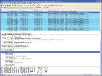
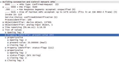
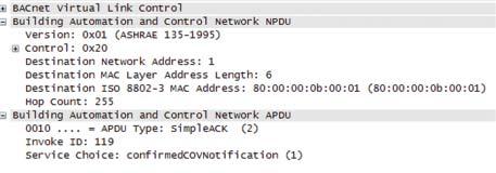
203 (5) Subscribe COV Request Response (6) COV Notification Notification BUILDING MANAGEMENT SYSTEM Response 203
VRF. Technical Data Book. Control System
 VRF Technical Data Book Control System I. Individual Control Systems II. Centralized control systems 1 2 3 Receiver & display unit 1 MRK-A10N 1) Features..................... 10 2) Wiring.......................
SINGLE. Technical Data Book Zone Control Systems
 SINGLE Technical Data Book Zone Control Systems Zone control system 2 I. Zone control system 1 Zone controller & remote temperature sensor 1. MWRZS00 / MWRZS10 / MRWTS 1) Features.... 4 2) Product specification...
Air Conditioner. user manual. imagine the possibilities. Data Management Server2. BACnet Gateway. LonWorks Gateway EN DB A(1) MIM-D00AN
 MIM-D00AN") Data Management Server2 MIM-D00AN BACnet Gateway MIM-B17N LonWorks Gateway MIM-B18N Air Conditioner user manual This manual is made with 100% recycled paper. imagine the possibilities Thank you for purchasing
Data Management Server2 MIM-D00AN BACnet Gateway MIM-B17N LonWorks Gateway MIM-B18N Air Conditioner user manual This manual is made with 100% recycled paper. imagine the possibilities Thank you for purchasing
The UP and DOWN buttons will toggle or scroll through the options in each section.
 TECHNICAL BULLETIN: MWR-WE10, MWR-WE10N, MWR-WE11N Page 1 of 10 Throughout the scheduling process, the LEFT and RIGHT buttons will move forward and backward through each section of settings The UP and
Wired Controller Operation & Installation Manual
 Wired Controller Operation & Installation Manual YR-E16A CONTENT Parts and Functions... 1 Operation... 8 Wired Controller Wiring Instruction... 31 Please read this operation manual before using the air
Owner s Manual RBC-AX32U(W)-E RBC-AX32U(WS)-E AIR CONDITIONER (SPLIT TYPE) Wireless remote controller kit. Model name: English.
-E RBC-AX32U(WS)-E AIR CONDITIONER (SPLIT TYPE) Wireless remote controller kit. Model name: English.") AIR CDITIER (SPLIT TYPE) Owner s Manual Wireless remote controller kit Model name: RBC-AX3U(W)-E RBC-AX3U(WS)-E Generic model name RBC-AX3U(W)-E Wireless remote controller model name WH-LSE Signal receiving
AIR CDITIER (SPLIT TYPE) Owner s Manual Wireless remote controller kit Model name: RBC-AX3U(W)-E RBC-AX3U(WS)-E Generic model name RBC-AX3U(W)-E Wireless remote controller model name WH-LSE Signal receiving
Two remote controller system with one Lossnay Basic System (Refer to page C-10) Multiple Lossnay units with one remote controller.
 Multiple Lossnay units with one remote controller.") Control CHAPTER 1 System Design 1. System Examples One with one remote Multiple units with one remote Two remote system with one Basic System (Refer to page C-10) Non-polar Two wires Power supply Remote
Control CHAPTER 1 System Design 1. System Examples One with one remote Multiple units with one remote Two remote system with one Basic System (Refer to page C-10) Non-polar Two wires Power supply Remote
Communicating Wall Control Owner s Manual TSTAT0101SC
 C O M M U N I C A T I N G S Y S T E M Communicating Wall Control Owner s Manual TSTAT0101SC U.S. Patent No. 7,243,004 U.S. Patent No. 7,775,452 616 02 1018 00 02/28/14 Table of Contents Introduction...
76 F. Ductless Split Air Conditioner. YR-E16b Wired Controller User Manual WARNING
 Ductless Split Air Conditioner YR-E16b Wired Controller User Manual Set temp. 76 F Indoor temp. 70 F Indoor humidity 32%RH Qty. online Standby Defrost Master Outdoor temp. 36 F Outdoor humidity 32%RH Mode
WIRED REMOTE CONTROLLER OPERATION MANUAL
 WIRED REMOTE CONTROLLER OPERATION MANUAL BRCE6 Thank you for purchasing this product. This manual describes safety precautions required for the use of the product. Read this manual carefully and be sure
IntesisBox. v.0.1. User Manual Issue Date: 12/2017 r1.3 EN
 IntesisBox HS-RC-MBS-1 v.0.1 Modbus RTU (EIA-485) Interface for Hisense air conditioners. Compatible with commercial line of air conditioners commercialized by Hisense. User Manual Issue Date: 12/2017
INTERFACE SPECIFICATION
 INTERFACE SPECIFICATION MODBUS CONVERTOR UTY-VMGX PART NO. 9708438030 Modbus is registered trademarks of Schneider Electric SA. LONWORKS is registered trademark of Echelon Corporation in the United States
OPERATION INSTRUCTIONS
 2018 Lennox Industries Inc. Dallas, Texas, USA OPERATION INSTRUCTIONS V0STAT52 Wireless Indoor Unit Controller CONTROLS 507459-04 05/2018 This manual must be left with the owner for future reference. IMPORTANT
Daikin HVAC Controls Guide Specification
 Part 1 - General VARIABLE REFRIGERANT VOLUME (VRV) HVAC SYSTEM Advanced Multi-zone Controller 1.01. Physical characteristics A. General: The advanced multi-zone controller shall be made from plastic materials
DVM CHILLER. Installation manual. FCU Application KIT MIM-F00N
 DVM CHILLER Installation manual FCU Application KIT MIM-F00N Thank you for purchasing this Samsung Product. Before operating this unit, please read this Installation manual carefully and retain it for
Chilled Water REMOTE CONTROLLER OPERATION MANUAL MAN-O-CRC4AH intensity.mx
 Chilled Water REMOTE CONTROLLER OPERATION MANUAL intensity.mx MAN-O-CRC4AH-061 CONTENTS Remote Controller Specifications---------------------------------------1 Performance Features-----------------------------------------------------1
VRF Control System. Judy Ouyang Technical Support Engineer
 VRF Control System Judy Ouyang Technical Support Engineer Individual Centralized BMS Gateway Intelligent Control PC/Network 1 Individual control 2 Centralized control 1.1 Wireless controllers 1.2 Wired
IntesisBox ModBus RTU Fujitsu Air Conditioning
 IntesisBox ModBus RTU Fujitsu Air Conditioning Compatible with Domestic and VRF line air conditioners commercialized by Fujitsu User Manual 03/2019 r1.0 eng Intesis Software S.L.U. 2019 All Rights Reserved.
AC Smart Advanced Control Smart Web Guide
 AC Smart Advanced Control Smart Web Guide PQCSW320A0E LG ENGLISH ITALIANO ESPAÑOL FRANÇAIS DEUTSCH Note Please read this installation/use manual before installing the product. Install the product with
 Page 1 of 7 Job Name Location Purchaser Engineer Submitted to Reference Approval Construction Unit Designation Schedule # Features LonWorks Gateway Control gateway that allows control and monitoring of
INSTALLATION MANUAL Wired Remote Control
 INSTALLATION MANUAL Wired Remote Control MWR-SH00 System Air Conditioner E DB98-28133A(1) Safety Precautions This installation manual describes how to install the wired remote control. For installation
Central Controller G-50A/GB-50 Web Browser Operation Manual (For Managers)
") Mitsubishi Electric Building Air-conditioner Control System Central Controller G-50A/GB-50 Web Browser Operation Manual (For Managers) Contents 1 Introduction...1 1-1 Conventions Used in This Manual...1
Mitsubishi Electric Building Air-conditioner Control System Central Controller G-50A/GB-50 Web Browser Operation Manual (For Managers) Contents 1 Introduction...1 1-1 Conventions Used in This Manual...1
NOTE CONTENTS NOTE-CONTENTS
 NOTE 1.The outline figure on cover is for reference only, which may differ from what you purchased. 2. Make sure to read chapter PRECAUTIONS before you operate the air conditioner. 3. This manual is available
IntesisBox PA-AC-MBS-1
 IntesisBox PA-AC-MBS-1 v.2.3 Modbus RTU (EIA-485) Interface for Panasonic air conditioners. Compatible with Etherea line air conditioners commercialized by Panasonic. User s Manual Issue Date: 11/2017
Pocket Quick Reference Guide On the TOSHIBA
 Pocket Quick Reference Guide On the TOSHIBA RBC-AMS51E / RBC-AMS54E Remote Controller Quick Reference Guide To assist service engineers working on Toshiba air conditioning equipment, there is a large quantity
KNX is a European Standard Protocol used for household and industrial Buliding Management System (BMS).
.") PRODUCT NEWS Products News: New HC-A16KNX PAGE 1 / 8 Summary 1. This advanced product news introduces the new product HC-A16KNX. 2. The details are indicated in the description. Description 1. Applicable
PRODUCT NEWS Products News: New HC-A16KNX PAGE 1 / 8 Summary 1. This advanced product news introduces the new product HC-A16KNX. 2. The details are indicated in the description. Description 1. Applicable
OWNER S MANUAL WIRE CONTROLLER OF AIR CONDITIONER. MODEL: KJR-12B/DPBG(T)-E Brivis Part No:B026000
-E Brivis Part No:B026000") OWNER S MANUAL WIRE CONTROLLER OF AIR CONDITIONER MODEL: KJR-12B/DPBG(T)-E Brivis Part No:B026000 Brivis Climate Systems Pty Ltd Tel:1300 BRIVIS brivis.com.au Thank you very much for purchasing our product.
OWNER S MANUAL WIRE CONTROLLER OF AIR CONDITIONER MODEL: KJR-12B/DPBG(T)-E Brivis Part No:B026000 Brivis Climate Systems Pty Ltd Tel:1300 BRIVIS brivis.com.au Thank you very much for purchasing our product.
RTD-NET Installation Instructions
 LED3 SW1 LED4 RTD-NET Installation Instructions 0V +V POWER 15-24VDC English RTD-NET Installation Instructions 100.00 RTD-NET Control Interface realtime Control Systems REMC P1 P2 RS485 D-BUS DB DA GND
Operation Guide CT101
 Operation Guide CT101 PG 1 The CT101 communicating Z-Wave thermostat operates via a high-quality, easy-to-use touch screen. To set or adjust your CT101, simply touch your finger firmly to the screen. The
REMOTE CONTROLLER CS244-R OWNER S MANUAL
 OWNER S MANUAL REMOTE CONTROLLER Please read this Owner's Manual carefully before operation. Save this manual in a safe place for future reference. CS-R . After setting the TIMER, there will be a one-half
Lossnay Remote Controller
 Remote Controller . Summary Technical manual detailing the control and operation of commercial-type units (LGH-RX5-E Series). Possible System Configurations () When using only the remote. (2) Linking
Pocket Quick. Reference Guide. On the TOSHIBA RBC-AMS51E. Remote Controller
 Pocket Quick Reference Guide On the TOSHIBA RBC-AMS51E Remote Controller Quick Reference Guide To assist service engineers working on Toshiba air conditioning equipment, there is a large quantity of data
MM-A20 BMS Interface for Mitsubishi Electric Split Air-Conditioning
 MM-A20 BMS Interface for Mitsubishi Electric Split Air-Conditioning Installation and User Guide www.microtrol.co.uk Contents 1. Supplied Parts...2 2. Important Information...3 3. Product Overview...4
Service Section. December 2003
 Service Section December 2003 Network Interface Module (NIM) Family Transceiver Boards NIM NIM PC Ver 2 S-NIM G-WAY NIM TELE Transceiver Boards (TX Boards) Extend the communication distance between the
IntesisBox. v.2.5. User Manual Issue Date: 12/2017 r1.9 EN. Modbus RTU (EIA-485) Interface for Fujitsu air conditioners.
 Interface for Fujitsu air conditioners.") IntesisBox FJ-RC-MBS-1 v.2.5 Modbus RTU (EIA-485) Interface for Fujitsu air conditioners. User Manual Issue Date: 12/2017 r1.9 EN Order Codes: FJ-RC-MBS-1: Modbus RTU Interface for Fujitsu air conditioners
IntesisBox FJ-RC-MBS-1 v.2.5 Modbus RTU (EIA-485) Interface for Fujitsu air conditioners. User Manual Issue Date: 12/2017 r1.9 EN Order Codes: FJ-RC-MBS-1: Modbus RTU Interface for Fujitsu air conditioners
VRF. Technical Data Book. DVM S Eco 8, 9 HP
 VRF Technical Data Book DVM S Eco 8, 9 HP Version Modification Date Remark Ver.1.0 Released DVM S Eco 8,9HP TDB.06.26 Ver.1.1 Max pipe length modified(equivalent length) : 0 -> 130m 15.04.07 Nomenclature
QUICK REFERENCE. Remote controller BRC1E51
 QUICK REFERENCE 1 2 3 4 1 2 1 2 6 9 2 3 4 5 7 6 8 1 10 mm L 120 19 120 mm 2 2 5 7 1+2 2 1 3 7 5 4 2 6 8 8.1 P1 P2 1 8.2 P1 P2 1 PCB 2 PCB 2 5 3 3 4 5 1x 1x 4 8.4 8.1 8.4 8.2 8.3 8.4 4 4 5 P1 P2 1 5 P1
Operation Guide CT100
 Operation Guide CT100 PG 1 The CT100 communicating Z-Wave thermostat operates via a high-quality, easy-to-use touch screen. To set or adjust your CT100, simply touch your finger firmly to the screen. The
STRA-17 Room controller. Installation and maintenance manual. Content
 Content Installation preparations... Wiring diagram...3 Display handling...5 Technical data...6 Configuration...7 Operating modes...7 Controller modes...7 Activation operating modes...7 Control states...8
ZONETOUCH DAMPER CONTROL SYSTEM Operation Manual
 ZONETOUCH DAMPER CONTROL SYSTEM Operation Manual www.zonemaster.com.au www.polyaire.com.au 2012 Polyaire Pty Ltd TABLE OF CONTENTS 1) Features 2 2) Wall Controller Layout (Touchpad) 2 3) Manual On/Off
Daikin HVAC Controls Guide Specification
 VARIABLE REFRIGERANT VOLUME (VRV) HVAC SYSTEM Building Management System Integration (Open Protocol Interface) Part 1 - General 1.01. Physical characteristics A. General: The VRV Controls Network shall
V0STAT51P-2 Programmable Wired Controller
 PRODUCT SPECIFICATIONS VARIABLE REFRIGERANT FLOW SYSTEMS VRF V0STAT51P-2 Programmable Wired Controller Bulletin No. 210766 March 2016 Grouping - Controller can control up to 16 indoor units on the same
Single phase. Technical Support Division
 Single phase Technical Support Division 2014.12 CMV MINI VRF System - Control System 1 1. Outdoor Unit and Indoor Unit PCB 2. Communication System 3. Controllers 2 CMV MINI VRF System - Control System
Installation Manual. DZK BACnet
 Installation Manual DZK BACnet InterfacepbilCodarPageNumber TABLE OF CONTENTS Page Overview... 5 Outline and Features... 5 System outline... 5 Specifications and device elements... 6 Functional specifications...
Wall mounted units. Please read carefully and thoroughly this manual before operating this unit and save it in a safe place for future reference.
 OWNERS' MANUAL REMOTE CONTROLLER Wall mounted units Please read carefully and thoroughly this manual before operating this unit and save it in a safe place for future reference. Warning. Be sure there
DESCRIPTION OF MODBUS CONNECTION
 DESCRIPTION OF MODBUS CONNECTION MODBUS CONNECTION There is a possibility to control Air Handling Unit (AHU) from external management system (BMS), which work with MODBUS data processing. For MODBUS connection
Modbus RTU (EIA-485) Interface for Panasonic and Sanyo air conditioners. Compatible with ECOi and PACi line models.
 Interface for Panasonic and Sanyo air conditioners. Compatible with ECOi and PACi line models.") IntesisBox PA-RC2-MBS-1 v.2.3 Modbus RTU (EIA-485) Interface for Panasonic and Sanyo air conditioners. Compatible with ECOi and PACi line models. User Manual Issue Date: 11/2017 r2.3 EN Order Codes: PA-RC2-MBS-1:
IntesisBox PA-RC2-MBS-1 v.2.3 Modbus RTU (EIA-485) Interface for Panasonic and Sanyo air conditioners. Compatible with ECOi and PACi line models. User Manual Issue Date: 11/2017 r2.3 EN Order Codes: PA-RC2-MBS-1:
REMOTE CONTROLLER RG57 Function Selection Manual
 REMTE CNTRLLER RG57 Function Selection Manual www.mundoclima.com Thank you very much for purchasing our products. Please read this manual carefully before using the remote controller. RG57B2/BGE CL94774
Wireless Remote Controller Kit
 INSTALLATION MANUAL Wireless Remote Controller Kit LS BRC4C8 Read these instructions carefully before installation. Keep this manual in a handy place for future reference. This manual should be left with
OPERATION MANUAL. Remote controller BRC1D527
 OPERATION MANUAL 1 3 6 23 7 8 9 2 1 4 12 14 17 10 11 22 25 16 13 15 18 19 20 21 5 24 29 33 26 35 27 36 37 28 30 31 32 34 1 2 Start 5s 5s 5s 5s + 5s End 2 WARNING - Never let the remote controller get wet,
QUICK START. Installation & Programming Guide
 QUICK START Installation & Programming Guide PRECAUTIONS READ AND FOLLOW ALL SAFETY INSTRUCTIONS. CAUTION - RISK OF ELECTRICAL SHOCK. To prevent electrical shock, turn off power at the circuit breaker
INSTRUCTIONS FOR USING THE CONTROL PANEL
 DIGIT SED ELECTRONIC CONTROLLER WITH LCD DISPLAY 1.09.370E 10.01.2007 VALLOX These instructions replace and complement the instructions for use and maintenance of the following VALLOX units: VALLOX DIGIT
TECHNICAL MANUAL (CONTROLS) Models. Lossnay Unit. Lossnay Remote Controller LGH-150RX3-E LGH-25RX3-E LGH-35RX3-E LGH-50RX3-E LGH-80RX3-E LGH-100RX3-E
 Models. Lossnay Unit. Lossnay Remote Controller LGH-150RX3-E LGH-25RX3-E LGH-35RX3-E LGH-50RX3-E LGH-80RX3-E LGH-100RX3-E") TECHNICAL MANUAL (CONTROLS) Models Unit LGH-15RX3-E LGH-25RX3-E LGH-35RX3-E LGH-50RX3-E LGH-80RX3-E LGH-100RX3-E LGH-150RX3-E LGH-200RX3-E Remote Controller PZ-41SLB-E PZ-52SF-E CONTENTS 1. Summary...............................................................................
TECHNICAL MANUAL (CONTROLS) Models Unit LGH-15RX3-E LGH-25RX3-E LGH-35RX3-E LGH-50RX3-E LGH-80RX3-E LGH-100RX3-E LGH-150RX3-E LGH-200RX3-E Remote Controller PZ-41SLB-E PZ-52SF-E CONTENTS 1. Summary...............................................................................
Viconics VT76x6W Water-source Heat Pump Controllers Engineering Guide Specification
 Viconics VT76x6W Water-source Heat Pump Controllers Engineering Guide Specification General The VT76xxW series is designed for single-stage and multi-stage control of water source heat pumps with dedicated
Daikin HVAC Controls Guide Specification
 Part 1 - General VARIABLE REFRIGERANT VOLUME (VRV) HVAC SYSTEM Advanced Multi-zone Controller 1.01. Physical characteristics A. General: The advanced multi-zone controller shall be made from plastic materials
DESIGN & TECHNICAL MANUAL
 AIR CONDITIONER Duct type DESIGN & TECHNICAL MANUAL INDOOR ARYG72LHTA ARYG90LHTA OUTDOOR AOYG72LRLA AOYG90LRLA DR_AR012EF_03 2017.04.07 Notices: Product specifications and design are subject to change
Operation Guide CT32 ENGLISH
 Operation Guide CT32 The CT32 communicating thermostat operates via a high-quality, easy-to-use touch screen. To set or adjust your CT32, simply touch your finger firmly to the screen. The screen will
Owner's Manual. Carrier TOSH BA REMOTE CONTROLLER FOR AIR CONDITIONER (SPLIT TYPE) Wireless remote controller kit TCB-AX21 UL
 Wireless remote controller kit TCB-AX21 UL") TOSH BA Carrier REMOTE CONTROLLER FOR AIR CONDITIONER (SPLIT TYPE) Owner's Manual Remote Controller Model name: Wireless remote controller kit TCB-AX21 UL Generic model name Wireless remote controller
TOSH BA Carrier REMOTE CONTROLLER FOR AIR CONDITIONER (SPLIT TYPE) Owner's Manual Remote Controller Model name: Wireless remote controller kit TCB-AX21 UL Generic model name Wireless remote controller
RoomMaster ABR-2. Commissioning
 Commissioning Content GENERAL Locking of operating mode keys...3 Control panel...3 Function of operating mode keys, operating menu...3 Activation of setting keys...4 Locking of setting keys...4 Setting
Options Overview. February 6, Ben Newell
 Options Overview February 6, 2018 Ben Newell CERV2 Configuration Unitary All-in-One System Heat pump and dampers Fans same ECM fans as current CERV Fresh air and return filters (nom. 10 x20 ) Integrated
INDOOR UNIT CONTROLLER (IUC) Operation Manual
 Operation Manual") INDOOR UNIT CONTROLLER (IUC) Operation Manual Date: 9 June 2015 Issue: 4 Note: Information in this document applies to IUC controllers programmed with software version 1.5. Page 1 of 11 Contents 1. Introduction...
INDOOR UNIT CONTROLLER (IUC) Operation Manual Date: 9 June 2015 Issue: 4 Note: Information in this document applies to IUC controllers programmed with software version 1.5. Page 1 of 11 Contents 1. Introduction...
3000 CONTROLLER TRAINING MANUAL. April 26, 2012 Software Version
 3000 CONTROLLER TRAINING MANUAL April 26, 2012 Software Version 1.59.03 Contents 3000 CONTROLLER USER GUIDE Quick Reference: Using the 3000... 3 Menu Summary Tree... 6 Main Menu: Programming your Fryer...
Wifi Smart. Thank you for choosing our product. For proper operation, please read and keep this manual carefully.
 Wifi Smart Thank you for choosing our product. For proper operation, please read and keep this manual carefully. Content Download and install App... 1 Configuration... 1 Functions introduction... 3 User
MXM-50. Modbus Interface for Mitsubishi Air-Conditioning. Installation and User Guide.
 MXM-50 Modbus Interface for Mitsubishi Air-Conditioning Installation and User Guide www.innon.co.uk 1. Product Overview The Black Pear MXM-50 unit allows a Modbus building management system (BMS) to monitor
Central Controller Operation & Installation Manual
 Central Controller Operation & Installation Manual YCZ-A004 CONTENT Function introduction of central controller... 1 Part info for central controller... 2 Page & Key Explanation... 4 Address Setting When
REMOTE CONTROLLER OWNER'S MANUAL AIR CONDITIONER OWNER'S MANUAL ATI/AOU-53HPR1 ATI/AOU-105HPS3 ATI/AOU-140HPS3
 OWNER'S MANUAL ОПИСАНИЕ ПУЛЬТА ДИСТАНЦИОННОГО УПРАВЛЕНИЯ AIR CONDITIONER REMOTE ROLLER ДЛЯ КОНДИЦИОНЕРА ILLUSTRATION OWNER'S MANUAL REMOTE CONTROLLER : ACI/AOU-35HPR1 ACI/AOU-53HPR1 ACI/AOU-71HPR1 ACI/AOU-105HPS3
M2 OLED Temperature Monitor Instructions PN 1841
 M2 OLED Temperature Monitor Instructions PN 1841 Installation Checklist Check for components included Read Warning and Cautions Read page 3 for mounting instructions Read System Overview, Mounting Considerations,
IntesisBox TO-RC-MBS-1
 IntesisBox TO-RC-MBS-1 v.1.5 MODBUS RTU (EIA485) Interface for Toshiba air conditioners from the Digital Inverter & VRF lines. User Manual Issue Date: 01/2014 Order Codes: TO-RC-MBS-1 Intesis Software
technical data Systems Individual control systems
 technical data Systems Individual control systems Individual control systems 17 1 Possible individual control systems...2 2 BRC2A51 - Simplified remote control Explanation of buttons and functions... 3
AirTouch 2 Zone Control System
 AirTouch 2 Zone Control System User Manual www.polyaire.com.au 2016 Polyaire Pty Ltd Liability Please read the instructions before installing this Zonemaster Zoning Control System. Polyaire Pty Ltd does
PLXRMM1605. Wall Mounted. FT-A Series. COOLING ONLY [50Hz] V
![PLXRMM1605. Wall Mounted. FT-A Series. COOLING ONLY [50Hz] V](/thumbs/96/128248561.jpg "PLXRMM1605. Wall Mounted. FT-A Series. COOLING ONLY [50Hz] V") PLXRMM1605 Wall Mounted FT-A Series COOLING ONLY [50Hz] 220-240V COMFORT 1 Daikin s FT-A series A simple, stylish and sleek wall mounted air conditioner that blends into any environment, providing the
PLXRMM1605 Wall Mounted FT-A Series COOLING ONLY [50Hz] 220-240V COMFORT 1 Daikin s FT-A series A simple, stylish and sleek wall mounted air conditioner that blends into any environment, providing the
Installation & Operation Manual
 The 2nd-Generation Centralized Controller for Indoor Units: DTC-IHXR Installation & Operation Manual Please keep this specifications Manual properly. Read this specifications Manual carefully before using
ExactLogic BACnet Communicating Thermostat EXL01816 Sequence Datasheet
 ExactLogic BACnet Communicating Thermostat EXL01816 Sequence Datasheet DataSheet ev 1.12.307/4.0 Jun 20, 2018 Operating Sequence Standard Occupied During normal occupied operation the display will show
ThermoPad Reference Manual
 ThermoPad Reference Manual Revision 0.6 www.coolautomation.com 2/18/2015 2 Table of Contents 1 Revision History 3 2 Specification 4 3 Thermopad Models 5 4 Terminals 6 5 MODBUS Map 7 6 Special Features
The PanasonicVRF Driver
 The PanasonicVRF Driver The PanasonicVRF driver interfaces to a Panasonic or Sanyo variable refrigerant flow (VRF) air conditioning system. Compatible VRF systems include Panasonic ECOi, ECO G, and Sanyo
INTRODUCTION. FX-1 Operations Manual. Standard Features. Optional Features. Read This Manual Completely Before Proceeding!
 INTRODUCTION The FX-1 Control is designed for use with all direct expansion, reverse cycle air conditioning systems. FX-1 has a universal power supply that operates on 115, 230, 50 or 60 Hz AC power. FX-
Air-conditioner Network System Centralized Controller AG-150A AG-150A-A GB-50ADA-J
 Air-conditioner Network System Centralized Controller AG-150A AG-150A-A GB-50ADA-A GB-50ADA-J Instruction Book (Web browser for System maintenance engineer) Contents 1 Introduction...2 1-1 Terms Used in
Networkable Dual Duct VAV Controller Specification and Installation Instructions
 Controller Models EVCBM14NIT2S (Master controller / 2 TRIACs) EVCS14N (Slave controller) TRL Series Thermostat TRL24 (Room Sensor: Temp) TRLH24 (Room Sensor: Temp and %RH) TRLG24 (Room Sensor: Temp and
Instruction Book. English. CITY MULTI Control System and Mitsubishi Mr. Slim Air Conditioners MA Remote Controller PAR-31MAA
 English CITY MULTI Control System and Mitsubishi Mr. Slim Air Conditioners MA Remote Controller PAR-31MAA Instruction Book Prior to use, thoroughly read the instructions in this manual to use the product
RS Stock No Instruction Manual RS Input Data Logging Thermometer
 RS Stock No. 730-0458 Instruction Manual RS-1384 4 Input Data Logging Thermometer EN FR IT DE ES TABLE OF CONTENTS / EN TITLE TABLE OF CONTENTS PAGE 1. INTRODUCTION FEATURE... 1 2. SPECIFICATIONS... 2
Touchpad User Guide. National Sales. Product Support. Freecall: Ph:
 Touchpad User Guide National Sales Ph: 1300 306 125 sales@ias.net.au Product Support Freecall: 1800 354 434 support@ias.net.au Designed and Manufactured in Australia by: Innovative Air Systems Pty Ltd.
3. Alignment and Adjustments
 3. 3-1 Test Mode How to Approach Test Mode You can approach the Test Mode by pressing the on/off switch of indoor unit for 5 seconds. on/off switch Test Mode Operation Option After installing the air conditioner,
SERVICE Manual DUCT TYPE AIR CONDITIONER. (Cool) OUTDOOR UNIT INDOOR UNIT TYPE UDH4400G DH44ZAX IDH4400A DH44ZA1(A2) ADH4400G DH44ZA1(A2)
 OUTDOOR UNIT INDOOR UNIT TYPE UDH4400G DH44ZAX IDH4400A DH44ZA1(A2) ADH4400G DH44ZA1(A2)") DUCT TYPE AIR CONDITIONER (Cool) TYPE ADH4400G DH44ZA(A2) INDOOR UNIT IDH4400A DH44ZA(A2) OUTDOOR UNIT UDH4400G DH44ZAX SERVICE Manual AIR CONDITIONER CONTENTS. Product Specifications 2. Installation 3.
DUCT TYPE AIR CONDITIONER (Cool) TYPE ADH4400G DH44ZA(A2) INDOOR UNIT IDH4400A DH44ZA(A2) OUTDOOR UNIT UDH4400G DH44ZAX SERVICE Manual AIR CONDITIONER CONTENTS. Product Specifications 2. Installation 3.
SMART VENTILATION MANAGEMENT: CHANGING THE WAY WE THINK ABOUT VENTILATION
 SMART VENTILATION MANAGEMENT: CHANGING THE WAY WE THINK ABOUT VENTILATION VENTILATION: THE KEY TO HEALTHY & EFFICIENT BUILDINGS At Ventacity Systems we believe that ventilation deserves more attention
ExactLogic BACnet Communicating Pressure Dependent VAV Damper Control with Heat EXL01820 Sequence Datasheet
 ExactLogic BACnet Communicating Pressure Dependent VAV Damper Control with Heat EXL01820 Sequence Datasheet DataSheet ev 1.12.307/4.0 June 14, 2018 Operating Sequence Standard Occupied During normal occupied
IntesisBox. v.1.3. User Manual Issue Date: 04/2016. IntesisBox PA-RC2-MBS-4
 IntesisBox PA-RC2-MBS-4 v.1.3 MODBUS RTU (EIA485) Interface for Panasonic and Sanyo air conditioners. Compatible with ECOi and PACi line models. User Manual Issue Date: 04/2016 Order Codes: PA-RC2-MBS-4
Zone Manager INSTALLATION MANUAL 40KMC KMQ QNC QNQ
 40KMC------301 40KMQ------301 40QNC------3 40QNQ------3 INSTALLATION MANUAL Installation manual This control system only operates with indoor units of the following models: 40KMC------301 and 40KMQ------301
Temperature control unit
 Temperature control unit 5739 18/19 Installation manual Part. U3582A - 12/08-01 PC Contents 1 - Introduction 5 1.1 - Warnings and tips 5 1.2 - Contents of package 5 2 - Description of the Control unit
BACVIEW MANUAL Software Version 3.06 INSTALLATION AND OPERATION MANUAL
 BACVIEW MANUAL Software Version 3.06 INSTALLATION AND OPERATION MANUAL 641-K31 1 BACVIEW INSTALLATION AND OPERATION IMPORTANT: This manual is for use with controller ZONE I/O 560 FHP part number 641-224
Modbus Integration Integration for Modbus Functionality for VTR8300 Series
 Modbus Integration Integration for Modbus Functionality for VTR8300 Series Building Management System *For data visualization and analysis Modbus Controller VT8000 Series room controllers 2 TABLE OF CONTENTS
RCF-230CAD. Room controller with communication for fancoil applications with two analogue V DC outputs
 revision 04 2016 RCF-230CAD Room controller with communication for fancoil applications with two analogue 0...10 V DC outputs Intended to control heating and/or cooling in 2- or 4-pipe installations. Setpoint
Communicative controller for VAV systems
 FCR015 Communicative controller for VAV systems Summary FCR015 is a communicative controller for heating and cooling panels and a VAV (variable air volume) damper. It measures temperature and CO 2 concentration
RTD-RA. realtime. Installation Instructions. English A B. Installation Instructions Control Systems LEDS ALL DIMENSIONS IN MM
 RTD-RA Installation Instructions 37.50 LEDS 4 3 2 1 D English Installation Instructions 80.00 80.00 ALL DIMENSIS IN MM C realtime Control Systems A B LEDS 4 3 2 1 D S21 J3 J6 1 2 3 4 J5 5 6 7 0V S1 0V
R410A D2D_AU019E/
 R41A 2. : AUU18RCLX AUU24RCLX D2D_AU19E/ 27.6.11 2-1. FEATURE MODELS : AUU18RCLX / AOU18RLX AUU24RCLX / AOU24RLX FEATURES Easy maintenance The control box is easily accessible for maintenance work Wide
Air Conditioner. installation manual. imagine the possibilities DB A-02. PIM(Pulse Input Module) MIM-B16N
 MIM-B16N") PIM(Pulse Input Module) MIM-B16N Air Conditioner installation manual imagine the possibilities Thank you for purchasing this Samsung product. DB68-04502A-02 Contents Before installation Safety Precautions...3
PIM(Pulse Input Module) MIM-B16N Air Conditioner installation manual imagine the possibilities Thank you for purchasing this Samsung product. DB68-04502A-02 Contents Before installation Safety Precautions...3
RBC-AMS55E-ES RBC-AMS55E-EN
 Wired Remote Controller Model name: RBC-AMS55E-ES RBC-AMS55E-EN Read this manual before using the RBC- AMS55E-ES, RBC-AMS55E-EN remote controller. Refer to the Installation Manual supplied with the indoor
REMOTE CONTROL USER MANUAL QUICK CONNECT MINI-SPLIT
 COMFORT...BUILT TO LAST QUICK CONNECT MINI-SPLIT REMOTE CONTROL USER MANUAL FOR THE REMOTE CONTROL INCLUDED WITH YOUR PERFECT AIRE MINI-SPLIT AIR CONDITIONER Before using the remote control with your air
AirTouch 3 Zone Control System
 airtouch AirTouch 3 Zone Control System User Manual airtouch.net.au 2017 Polyaire Pty Ltd Liability Please read the instructions before installing this Zone Control System. Polyaire Pty Ltd does not accept
IntesisBox PA-AW-MBS-1 v.2.0
 IntesisBox PA-AW-MBS-1 v.2.0 Modbus RTU (EIA485) Interface for Panasonic Aquarea series. User Manual Issue Date: 08/2014 r2.0 Order Code: PA-AW-MBS-1: Modbus RTU Interface for Panasonic Aquarea series
CHILLED WATER. HIGH PRECISION AIR CONDITIONERS, FROM 7 TO 211 kw
 IT COOLING CLOSE CONTROL AIR CONDITIONERS CHILLED WATER HIGH PRECISION AIR CONDITIONERS, FROM 7 TO 211 kw 3 Versions available Single chilled water coil Double chilled water coil High temperature IT COOLING