EV Controls user Guide
|
|
|
- Loraine Jackson
- 6 years ago
- Views:
Transcription
1 EV Controls user Guide Copyright EV Controls
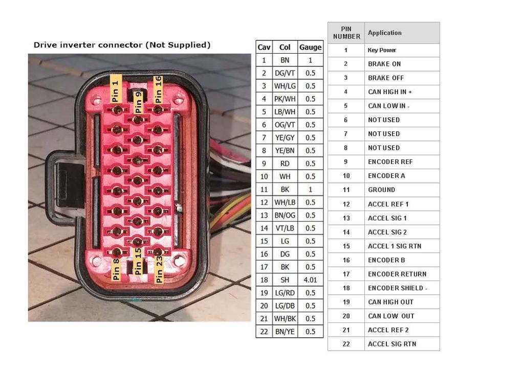
2 Table of Contents Introduction... EV Controls System Features... General guidelines for installation... Inverter Electrical Pinout Sheet... Drive Inverter Connections... High Voltage Contactor Circuit (T1-C Only)... EV Controls Control Panel Connector Pinout... OBD 2 Connector... Main Menu Screen... Home Screen... Setup Screen
3 Introduction Thank you for purchasing the EVControls Tesla drive unit controller. The EVControls control panel is a stand alone device designed to provide a user interface to for the control of a Tesla drive unit in an automotive chassis of the users choice. The EVControls Tesla drive unit controller is the result of 2 years of extensive research and development by Tapp Auto Inc. and is available in 2 versions the the EVControls T-1 and T-1C. Both units provide digital control of the Tesla drive inverter via CAN communication controlled by a multi function touch screen. More detail on the individual functions available in the EVControls T-1 and T-1C can be found on the system features page. Disclaimer Under no circumstances shall EV Controls be liable for direct, indirect, consequential or incidental damage or injury resulting from the use of EV Controls components in the construction and operation of custom built electric vehicle. The installation of the EV Controls controller requires that the end user the have a thorough understanding of applicable electrical principles and is fully aware of the inherent dangers of working with electric vehicle high voltage systems as they apply to the design, construction and operation of an electric vehicle. 2
4 EVControls T-1 System features The EV Controls T-1 is the base model controller for the Tesla drive unit. The EV Controls T-1 is designed to interface with the Tesla drive units via a touch screen and communicates the EVControls proprietary firmware to the drive unit via CAN bus digital messaging. The EVControls digital touch screen interface is programed to provide the operator with the following functionality. Select drive, neutral and reverse modes via the 7"touchscreen Adjust peak power output and regenerative braking power levels via the touchscreen Display the following data on the 7" touchscreen Drive mode (D, N,R) Traction pack voltage (HV) Inverter 12V supply voltage Accelerator position Stator current Actual power in kilowatts, positive or negative (regenerative braking) Max power limit Max regeneration power limit The EV Controls T-1C System features The EVControls T-1C builds on the functions provided in the EVControls T-1 interface but takes it a step further by providing additional microprocessor controlled outputs that automate startup procedures and add several important functions that simplify your build and add drive-ability and reliability. The EVControls T-1C controls both the S-85 and P-85 drive units at at this time, support for the smaller D drive units is in currently in development. Select drive, neutral and reverse modes via the 7" touchscreen Adjust peak power output and regenerative braking power levels via the touchscreen Display the following data on the 7" touchscreen Drive mode (D, N,R) Traction pack voltage (HV) Inverter 12V supply voltage Accelerator position Stator current Actual power in kilowatts, positive or negative (regenerative braking) Max power limit Max regeneration power limit Additional Features for EVControls T-1C 3
5 Additional Features for EVControls T-1C Brake lights operation; Brake light output is activated when the brake pedal is depressed or when regenerative braking exceeds a certain threshold. Inverter 12V power. Timed application of Inverter 12V power should only be applied at the correct point in the power up sequence, after CAN transmission has been initiated. Inverter cooling fan control. This output will trigger the inverter cooling fan at a user adjustable inverter coolant temperature, adjusted via the touchscreen. High voltage positive contactor. High voltage negative contactor. High voltage pre-charge relay. The controller will close the negative contactor, then the precharge relay, then after a set delay, it will close the positive contactor. this is to avoid welded contactors. The controller can also be configured to control a charger and DC/DC converter. The inverter firmware needs to be updated to a version that is compatible with our controller, and we can do this remotely. This product does not currently include a wiring harness. We suggest you source the inverter wiring harness, accelerator pedal, and brake pedal switch when you purchase the inverter. 4
6 What's included with your purchase The purchase of the EVControls interface includes the 7" touch control panel with connector and the proprietary software. The unit will arrive in a ready to use state however a reflash of the Tesla drive unit may be required. The new drive unit firmware if required will be uploaded from our servers at no additional cost. What you must provide This guide is based on the assumption that you will have the following components in your possession Suitable drive unit (please our support department to verify suitability) Drive unit wiring harness including inverter connector and shielded encoder harness with connector Tesla accelerator pedal with connector and a portion of the associated harness Brake switch with connector and a portion of the associated harness All associated wiring, fuses, contactors and switches A 12volt power source Wiring diagrams The following pages include details of the wiring schematics to help with your installation. Wiring color codes and pin locations assume you are using Tesla components. 5
7 6
8 7
9 8
 12 VOLT POWER INPUT O. FUSED (10 AMP) 12 VOLT POWER INPUT P. NOT USED Q. NOT USED R. CAN 1 LOW S. TERMINAL 1 ON INVERTER 9")
10 EVControls Pinout A. CAN 1 HIGH B. NOT USED C. NOT USED D. NOT USED E. INVERTER PUMP OUTPUT F. NOT USED G. POSITIVE CONTACTOR H. NEGATIVE CONTACTOR I. CHASSIS GROUNG J. KEY POWER K. NOT USED L. NOT USED M. PRE-CHARGE RELAY N. FUSED (10 AMP) 12 VOLT POWER INPUT O. FUSED (10 AMP) 12 VOLT POWER INPUT P. NOT USED Q. NOT USED R. CAN 1 LOW S. TERMINAL 1 ON INVERTER 9
11 10

12 Main Menu This screen is the main control and information feedback screen. Touch panel allows: ü Selection of desired drive range ü Monitoring of battery condition, regen level and power level ü Monitoring of brake switch condition ü Navigation to home screen for access to setup screen 11

13 Home Screen To access this screen use the Return to Home Screen Icon on the main menu screen. Gear icon will bring you to the setup screen. Steering wheel icon will return you to the main menu screen. 12

14 Setup Screen Purpose Allow user to select options best suited to their system setup. Must be accessed from the Home Screen Up/Down Arrows Max Power This function will allow user to set the maximum power level in kilowatts Maximum Regen Adjust sensitivity of regenerative braking force. Select from 0 to 100% Cooling Control Allow user to select cooling system on off set point - TC-1 only Speed Scaler Setting allows user to select different multipliers used in calculating the control panel speed readout On/Off Radio Buttons Inverter On Off Selection Allows deactivation of inverter with key on. This required to allow EVControls support to write new firmware to the inverter as it becomes available Inverter Fan On/Off Activate or deactivate inverter cooling fan. Inverter Coolant Pump 13

15 Inverter Coolant Pump Activate or deactivate inverter coolant pump Settings Selection Box Load Settings: Loads current system settings Save Settings: Saves new settings to memory Return to Main Menu Return user to Home Screen when settings are completed and saved to system memory. 14
User Manual. HyPer 9 IS. HyPer 9 IS User Manual Version 05 NetGain Motors, Inc. Page 1 of 27
 User Manual HyPer 9 IS HyPer 9 IS User Manual Version 05 NetGain Motors, Inc. Page 1 of 27 Table of Contents Warning and Caution... 4 Safety Information... 4 DISCLAIMER:... 5 Main Wiring Diagram... 6 Wire
AC SMARTMOTION CONTROLLERs
 AC SMARTMOTION CONTROLLERs for and Generic Slave FAULT LIST and TROUBLESHOOTING (Rev. 2.4: March 2016) SME S.p.A. Via della Tecnica, n 40 36071 Arzignano (VI) - ITALY Phone:+39 (0444) 470511 Fax: +39 (0444)
Diesel Particulate Filter DPF Service Regeneration Table 1: Service Regeneration Successful Table 2: Service Regeneration Unsuccessful
 Service Information 2007 Chevrolet Silverado - 4WD [1GCHK23657F529413] Sierra, Silverado VIN C/K Service Manual Engine Engine Controls and Fuel - 6.6L LMM Diagnostic Information and Procedures Document
INSTRUCTIONS EV100 HANDSET
 GEH-5716 GENERAL The Handset is a multi-functional tool to be used with the EV100/200 LX and LXT SCR controls. The Handset consist of a Light Emitting Diode (LED) display and a keyboard for data entry.
Regenerative Power Module And Common Bus RPM Panels Instruction Manual
 Regenerative Power Module And Common Bus RPM Panels Instruction Manual Part Number September 2010 Copyright 2010 Magnetek Material Handling PRODUCT MANUAL SAFETY INFORMATION Magnetek, Inc. (Magnetek)
User Manual. HyPer 9 IS. HyPer 9 IS User Manual Version 04 NetGain Motors, Inc. Page 1 of 23
 User Manual HyPer 9 IS HyPer 9 IS User Manual Version 04 NetGain Motors, Inc. Page 1 of 23 Table of Contents Warning and Caution... 4 Safety Information... 4 DISCLAIMER:... 5 Main Wiring Diagram... 6 Wire
1411 S. Roselle Rd. Schaumburg, IL Phone (847) Fax (847)
 Fax (847)") The Touch Screen Control System consists of two components, the Touch Screen (TS) and the Switch Panel Module(SPM). The PowerQuest system can control the switching of 8 circuits. 6 circuits are predefined
The Touch Screen Control System consists of two components, the Touch Screen (TS) and the Switch Panel Module(SPM). The PowerQuest system can control the switching of 8 circuits. 6 circuits are predefined
Integrated Battery Control System LBCS Step-by-Step Setup Guide
 Integrated Battery Control System LBCS Step-by-Step Setup Guide 1. Components of the System 2. Components of the System 3. LBCS Overview 4. Battery Connections 5. Sense Board Installation 6. Sense Board
Resolver to Digital Expansion Board
 Resolver to Digital Expansion Board Catalog No. EXB009A01 Installation and Operating Manual 6/98 MN1313 Table of Contents Section 1 General Information............................. 1-1 Introduction....................................
Energy Management System. Operation and Installation Manual
 Energy Management System Operation and Installation Manual AA Portable Power Corp 825 S 19 TH Street, Richmond, CA 94804 www.batteryspace.com Table of Contents 1 Introduction 3 2. Packing List 5 3. Specifications
User Guide Chevrolet Volt
 User Guide Chevrolet Volt Accessory Power Control Module General Motors Part Numbers 24262765 and 24261518 Copyright 2015 EVTV LLC 0 INTRODUCTION The Accessory Power Control Module, sometimes referred
Kodiak Mobile INTELLIGENT DOCKING STATION USERS MANUAL PART NUMBER: PANASONIC CF53 TOUGHBOOK COMPATIBLE AN ISO 9001:2008 CERTIFIED COMPANY
 CUSTOMER SERVICE If you have any questions or require additional information please contact Customer Service at 877-455-6886, Monday though Friday, 8:00am - 5:00pm CST. TECHNICAL SUPPORT Kodiak Mobile
RoboClaw 2x30A Dual Channel Motor Controller
 RoboClaw 2x30A, 34VDC Dual Channel Brushed DC Motor Controller Version 2.2 (c) 2016 Ion Motion Control. All Rights Reserved. Feature Overview: 60 Amps Peak Per Channel Channel Bridging Supported Dual Quadrature
INTELLIGENT DOCKING STATION USERS MANUAL
 Kodiak Mobile by Jotto Desk 209 W. Easy St., Rogers, AR USA 72756 Customer Service: 877.455.6886 http://www.kodiakmobile.com PART NUMBER: 450-4011 - Last Update: 06.2009 INTELLIGENT DOCKING STATION USERS
LDC14xx. 1x120A Single Channel Brushed DC Motor Controller with Encoder Input
 LDC14xx 1x120A Single Channel Brushed DC Motor Controller with Encoder Input Roboteq s LDC14xx controller is designed to convert commands received from an RC radio, Analog Joystick, wireless modem, PC
D115 The Fast Optimal Servo Amplifier For Brush, Brushless, Voice Coil Servo Motors
 D115 The Fast Optimal Servo Amplifier For Brush, Brushless, Voice Coil Servo Motors Ron Boe 5/15/2014 This user guide details the servo drives capabilities and physical interfaces. Users will be able to
Trouble Shooting Leveling Control Box Electric Jacks. Touch Pad LED Probable Cause Solution
 Trouble Shooting Leveling Control Box 140-1224 Electric Jacks Copyright Power Gear Issued: January 2013 #82-L0524, Rev. OA Touch Pad LED Probable Cause Solution 1. On/Off LED will not light 2. Wait LED
GBL19xx. 500A, 60/80/100V Single Channel Brushless DC Motor Controller. Preliminary - Subject to Change
 GBL19xx Preliminary - Subject to Change 500A, 60/80/100V Single Channel Brushless DC Motor Controller Roboteq s GBL19xx is a very high-current, features-packed motor controller for brushless DC motors.
Standard Operating Procedures
 1551 S. Vineyard Avenue Ontario, CA 91761 909-923-1973 Standard Operating Procedures Instructions for Program and Diagnose Modes Primary and Secondary Controllers Generic Software Version 5.14 and Higher
Innovative Circuit Technology Ltd.
 Innovative Circuit Technology Ltd. Pro Series DC Power Supply INSTRUCTION MANUAL 855-343-001 Models: ICT690-12S/ICT690-12SB ICT690-24S/ICT690-24SB ICT690-48S/ICT690-48SB ICT1190-12S/ICT1190-12SB ICT1190-24S/ICT1190-24SB
MDC1230/MDC x80A and 1x120A Single Channel Brushed DC Motor Controller with Encoder Input, USB and CAN
 MDC1230/MDC1460 1x80A and 1x120A Single Channel Brushed DC Motor Controller with Encoder Input, USB and CAN Roboteq s MDC1230 and MDC1460 controllers are designed to convert commands received from an RC
TB-100 ControLynx Terminal Block
 TB-100 ControLynx Terminal Block TECHNICAL MANUAL Version 1.3 September 2006 Copyright This technical manual and the equipment, firmware and software described herein are copyrighted by INTENT DIGITAL
Functional safety in BATTERY MANAGEMENT SYSTEMS
 Functional safety in BATTERY MANAGEMENT SYSTEMS LiTHIUM BALANCE history 2014 2015 2016 2011 2012 1 st OEM cust. in production 300 projects completed ISO 9001 certified 400 projects completed 500 projects
HP8440 Power Box. The Intelligent Power Distribution Module. Installation and User Guide for PCM Version 9.02
 HP8440 Power Box The Intelligent Power Distribution Module Installation and User Guide for PCM Version 9.02 1 Introduction The Power Control Module is an innovative, intelligent and programmable module
DVB-LR. Compatible with Landrover touch-screen navigation systems version 1
 dvblogic DVB-T Tuner Compatible with Landrover touch-screen navigation systems version 1 Product features full plug and play vehicle-specific dual DVB-T Tuner with two active DVB-T glass-mount antennas
RoboClaw 120A/160A/200A Dual Channel Motor Controller
 RoboClaw 2x160A, 34VDC Dual Channel RoboClaw 2x120AHV, 60VDC Dual Channel RoboClaw 2x160AHV, 60VDC Dual Channel RoboClaw 2x200AHV, 60VDC Dual Channel Brushed DC Motor Controllers Version 2.1 (c) 2016 Ion
Application Note. Common Bussing AC Drives. For 584SV and 620 series drives APP-AC-02
 Application Common Bussing AC Drives APP-AC-02 For 584SV and 620 series drives APP-AC-02 2004 SSD Drives inc. 9225 Forsyth Park Drive, Charlotte, NC 28273 Page of 6 Introduction On occasion, one or more
PMDX-105. I/O Option Riser Board User s Manual. Document Revision: 1.1 Date: 7 September 2004 PCB Revision: PCB-443A
 PMDX-105 I/O Option Riser Board User s Manual Date: 7 September 2004 PMDX Web: http://www.pmdx.com 7432 Alban Station Blvd., A105 Phone: +1 (703) 912-4991 Springfield, VA 22150-2321 USA FAX: +1 (703) 912-5849
Operator s Manual. Morbark Integrated Control System Woodhog Series Model 2600
 Operator s Manual Morbark Integrated Control System Woodhog Series Model 2600 Contents Introduction 4 Parts Identification 6 Display Module Display Pages 9 Main Page 11 Engine Information Page 12 Hydraulic
4200-DL Model # C-4200-DL DL Controller Instruction Manual V.1.0. This instruction manual serves as a guide for the 4200-DL Controller.
 4200-DL Controller Instruction Manual V.1.0 4200-DL Model # C-4200-DL This instruction manual serves as a guide for the 4200-DL Controller. IMPORTANT! Please read through all provided instructions and
DCS-E 1kW Series, DLM-E 3kW & 4kW Power Supplies
 DCS-E 1kW Series, DLM-E 3kW & 4kW Power Supplies M51A Option: Isolated Analog Programming Manual Power Supplies Elgar Electronics Corporation 9250 Brown Deer Road San Diego, CA 92121-2294 1-800-73ELGAR
MTX-A Temperature Gauge User Manual
 MTX-A Temperature Gauge User Manual 1. Installation... 2 1.1 Gauge Mounting... 2 1.2 Temperature Sensor Mounting... 2 1.2.1 Changing the MTX-A s Gauge Bezel... 2 1.3 Main Gauge Wiring... 3 1.3.1 Single
ADR. - Configuration and Functionality USER MANUAL
 ADR - Configuration and Functionality USER MANUAL Installation Contents Installation... 3 Dimensions... 3 Configuration... 4 Connection to the ADR... 4 Password Support... 5 Device Configuration... 5 Device
Standard Operating Procedures
 1790-105 La Costa Meadows San Marcos, CA 92078 (888) 591-5830 Standard Operating Procedures Instructions for Program and Diagnose Modes Primary and Secondary Controllers Generic Software Version 5.11 and
WIRING & CIRCUIT INFORMATION
 2))52$' 7+81'(5TM &+$37(5 WIRING & CIRCUIT INFORMATION WARNING: Failure to reconnect ground wires or replace metal shields may result in radio frequency interference. NOTICE: The term VGM refers to the
HP Proliant DL360 G6 Carrier-Grade Server Read Before Install
 HP Proliant DL360 G6 Carrier-Grade Server Read Before Install Carrier-Grade Instructions HP Part Number: COOPE-RRTF1 Published: September 2010 Edition: 1 Copyright 2010 Hewlett-Packard Development Company,
Modbus Register Map: Galaxy 300
 Modbus Map: Galaxy 300 Notes: 1. 16-bit are transmitted MSB first (i.e. big-endian). 2. INT32 UINT16 and and UINT32 are are most-significant word in in n+0, least significant word in in n+1 n+1 (i.e. (i.e.
VSX18xx. 500A + 25A DC Motor Controller
 VSX18xx 500A + 25A DC Motor Controller Roboteq's VSX18xx is a high current, dual channel motor controller composed of a unidirectional half-bridge capable of up to 500A and a 25A bidirectional power bridge.
USER S MANUAL. CNC Stepper Motor Control Box CS3EA4-1 Rev. 1
 USER S MANUAL CNC Stepper Motor Control Box CS3EA4-1 Rev. 1 April, 2012 USER'S MANUAL TABLE OF CONTENTS Page # Contents 1.0 FEATURES... 2 2.0 SPECIFICATIONS... 3 3.0 SYSTEM REQUIREMENTS... 3 4.0 WARNING...
DTC P0AA6 - High Voltage Isolation Fault
 DTC P0AA6 - High Voltage Isolation Fault Product Family Orion BMS [Original] (24-180 Cell) Orion BMS 2 (24-180 Cell) Orion JR (16 Cell) Fault Supported YES YES NO FAULT DESCRIPTION This code is set when
RST INSTRUMENTS LTD.
 Carlson/RST MA-7 Readout Instruction Manual 1 RST INSTRUMENTS LTD. Carlson/RST MA-7 Readout Instruction Manual Ltd. 11545 Kingston St Maple Ridge, BC Canada V2X 0Z5 Tel: (604) 540-1100 Fax: (604) 540-1005
SIRIUS CAPACITOR MODULE User Manual. Model number: A-1.7C-M-SD-G Version 1.0; Release Date: April 2018
 SIRIUS CAPACITOR MODULE User Manual Model number: 3550-48-A-1.7C-M-SD-G Version 1.0; Release Date: April 2018 Introduction The Sirius Capacitor Module ( Sirius ) is supercapacitor-based storage that uses
C4 SAFETY CHARGE PUMP BOARD Rev. 6.2
 C4 SAFETY CHARGE PUMP BOARD Rev. 6.2 User manual Rev. 1 1. Overview. This board takes advantage of Mach ability to send a specific frequency through one of the pins of the parallel port when the program
When any of the following symbols appear, read the associated information carefully. Symbol Meaning Description
 Vision OPLC V350-35-R34/V350-J-R34 Installation Guide The Unitronics V350-35-R34/V350-J-R34 offers the following onboard I/Os: 22 Digital Inputs, configurable via wiring to include 2 Analog and 3 HSC/Shaft-encoder
USER S MANUAL. CNC Servo Stepper Motor Control Box CH4EV12-1 Rev. 1
 USER S MANUAL CNC Servo Stepper Motor Control Box CH4EV12-1 Rev. 1 January, 2013 i USER'S MANUAL TABLE OF CONTENTS Page # Contents 1.0 FEATURES... 1 2.0 SPECIFICATIONS... 2 3.0 SYSTEM REQUIREMENTS... 2
Microsquirt-Module Developers Guide
 Microsquirt-Module Developers Guide Megasquirt-2 Product Range MS2/Extra 3.3 Dated: 2014-12-10 This version of the documentation applies to: MicroSquirt-module V2.2M as shown above. Does not apply to other
Digital Dash I/O Adapter Configuration
 Digital Dash I/O Adapter Configuration The I/O Adapter adds ten inputs/outputs to the 7 digital dash. These inputs and outputs can then be configured as gauges or switches, and data logged locally through
MT-150. RENOGY 150A Peak High Precision Watt Meter and Power Analyzer E. Philadelphia St., Ontario CA Version: 1.
 MT-150 RENOGY 150A Peak High Precision Watt Meter and Power Analyzer 0 2775 E. Philadelphia St., Ontario CA 91761 1-800-330-8678 Version: 1.1 Important Safety Instructions Please save these instructions.
MEGA DIAL PANEL Instructions
 2036 Fillmore Street Davenport, Ia. 52804 563-324-1046 www.racedigitaldelay.com MEGA DIAL PANEL Instructions WARRANTY AND DISCLAIMER DIGITAL DELAY ELECTRONICS INC. WARRANTS THE PRODUCTS IT MANUFACTURES
V0STAT51P-2 Programmable Wired Controller
 PRODUCT SPECIFICATIONS VARIABLE REFRIGERANT FLOW SYSTEMS VRF V0STAT51P-2 Programmable Wired Controller Bulletin No. 210766 March 2016 Grouping - Controller can control up to 16 indoor units on the same
4200 Model # - C Controller Instruction Manual V.3.1. This instruction manual serves as a guide for the 4200 Controller.
 4200 Controller Instruction Manual V.3.1 4200 Model # - C-4200 This instruction manual serves as a guide for the 4200 Controller. IMPORTANT! Please read through all provided instructions and any listed
VSX A Forward/Reverse Separate Excitation DC Motor Controller
 VSX1850 500A Forward/Reverse Separate Excitation DC Motor Controller Roboteq s VSX1850 is a high-current controller for Separate Excitation DC motors. The controller is composed of a unidirectional half-bridge
FDS3NAV2. For Ford Vehicles Equipped With SYNC3. Installation Instructions. Calibration and Setup Guide. Page 1 of 14
 FDS3NAV2 For Ford Vehicles Equipped With SYNC3 Installation Instructions Calibration and Setup Guide Page 1 of 14 Please read this manual thoroughly before installation. This manual illustrates a typical
Total Coach System. for Foretravel Users Manual. SilverLeaf Electronics, Inc Ferry St SW Albany, OR (888)
") Total Coach System for Foretravel Users Manual SilverLeaf Electronics, Inc. 2472 Ferry St SW Albany, OR 97322 (888) 741-0259 www.simply-smarter.com Overview The Total Coach System as installed by Foretravel
Total Coach System for Foretravel Users Manual SilverLeaf Electronics, Inc. 2472 Ferry St SW Albany, OR 97322 (888) 741-0259 www.simply-smarter.com Overview The Total Coach System as installed by Foretravel
SAT BMS. User Guide. Rev
 SAT BMS User Guide Rev001. 2015.11 CONTENTS 1 SAFETY... 3 1.1 General guidance... 3 2 SAT BMS Introduction... 4 2.1 General overview... 4 2.2 BMS General wiring structure... 4 2.3 Hardware... 4 2.4 Program...
Installation & Operation
 LED Readout Installation & Operation WARRANTY Accurate Technology, Inc. warrants the ProScale Systems against defective parts and workmanship for 1 year commencing from the date of original purchase. Upon
Instruction and Operations Manual
 1 GARTECH Enterprises, Inc. Rev 2 01-23-09 Instruction and Operations Manual Portable Test Cell Overview The primary purpose of the Portable Test Cell is to allow the user the ability to control the engine
8-Channel Relay Output Board Via I 2 C Protocol. I2C-Relay8
 I2C-Relay8 User Manual Table of Contents What Does it Do?... 3 What Do I Need to Make it Work?... 3 What Else Does it Work With?... 4 How to Use This Device... 5 Setting Up the Controller... 5 Powering
DODGE Challenger Charger Journey. 6-Pin Video Input Cable 6-Pin Audio In/Out Cable GPS Magnetic Antenna
 CHRYSLER 2011-2014 300c DODGE 2011-2014 Challenger 2011-2014 Charger 2011-2014 Journey FIAT 2011-2014 Freemont Plug and Play connectors make installation simple and easy. Utilizes the latest mapping version
OneControl PROGRAMMING MANUAL
 OneControl PROGRMMING MNUL Rev: 10.22.2018 OneControl Programming Manual TBLE OF CONTENTS Safety and System Information 2 System Information 2 Programming 3 Connecting The OneControl Tablet To The OneControl
FIM2360. Advanced Features 2 x 60A or 1 x 120A Variable Frequency Drive for AC Induction Motors
 FIM2360 Advanced Features 2 x 60A or 1 x 120A Variable Frequency Drive for AC Induction Motors Roboteq s FIM2360 is a features-packed, high-current, dual or single channel controller for AC Induction motors.
Master Pulse Reference/ Isolated Pulse Follower Expansion Board
 Master Pulse Reference/ Isolated Pulse Follower Expansion Board Catalog No. EXB005A01 Installation and Operating Manual 2/03 MN1312 Y1 Table of Contents Section 1 General Information.............................
Profibus DP Expansion Board
 Profibus DP Expansion Board Catalog No. EXB014A01 Installation and Operating Manual 8/03 MN1323 Table of Contents Section 1 General Information................................... 1-1 Introduction.........................................
V8/V80. Installation manual. Version 5.0
 V8/V80 Installation manual Version 5.0 LXNAV d.o.o. Kidričeva 24a, 3000 Celje, Slovenia tel +386 592 33 400 fax +386 599 33 522 info@lxnav.com www.lxnav.com 1 Important Notices 3 1.1 Limited Warranty 3
VIM Mercedes Benz Sprinter Contact Intermotive for additional applications
 An ISO 9001:2008 Registered Company VIM910 2017 Mercedes Benz Sprinter Contact Intermotive for additional applications Introduction The VIM will allow the OEM steering wheel switches to control aftermarket
Kodiak Mobile INTELLIGENT DOCKING STATION USERS MANUAL PART NUMBER: PANASONIC CF31 COMPATIBLE GETAC B300 COMPATIBLE
 CUSTOMER SERVICE If you have any questions or require additional information please contact Customer Service at 877-455-6886, Monday though Friday, 8:00am - 5:00pm CST. TECHNICAL SUPPORT Kodiak Mobile
USER S MANUAL. C4 SAFETY CHARGE PUMP BOARD Rev. 6.2
 USER S MANUAL C4 SAFETY CHARGE PUMP BOARD Rev. 6.2 March 2013 USER'S MANUAL TABLE OF CONTENTS Page # Contents 1.0 OVERVIEW... 1 2.0 FEATURES... 1 3.0 SPECIFICATIONS... 2 4.0 SIMPLIFIED SCHEMAT... 2 5.0
Abstract. GLV User Manual 1
 GLV User Manual 1 Abstract This user manual is a high level document that explains all operational procedures and techniques needed to operate the GLV system in a safe and effective manner. Anyone operating
SPECIAL INSTRUCTIONS FOR CAPACITORS COMPACT GENERATORS
 SPECIAL INSTRUCTIONS FOR CAPACITORS COMPACT GENERATORS (WITH CAPACITOR CHARGER BOARD A3517-02) The process depends on Generator and System configuration. This document applies to installation of Capacitors
FDC3260. Advanced Features Triple Channel 60A Brushed DC Motor Controller with USB and CAN
 FDC3260 Advanced Features Triple Channel 60A Brushed DC Motor Controller with USB and CAN Roboteq s FDC3260 is a features-packed, high-current, triple channel controller for brushed DC motors. The controller
CAN Test Box. User s Guide
 CAN Test Box User s Guide NOTICE User s Guide 1. Caution: As active LED signals may have the potential to interfere with CAN signals we do not recommend that you connect the CAN Test Box (CTB) to late
Operation Manual. Concorde 600 Power Supply. *This instrument is intended for laboratory use only.
 Concorde 600 Power Supply Operation Manual Cat.no. R10-1001011 *This instrument is intended for laboratory use only http://www.recenttec.com E-mail : support@recenttec.com Version 1.1 Packing List x 1
Safety Instructions 1-1 Avoid unintended Start General Description 2-2
 Contents Contents 1 Safety and precautions 1-1 Safety Instructions 1-1 Avoid unintended Start. 1-1 2 Introduction 2-1 General Description 2-2 3 Supported Configuration 3-1 Introduction 3-1 Fixed-speed
PduSetup User Manual. Professional Electronics for Automotive and Motorsport
 Professional Electronics for Automotive and Motorsport 6 Repton Close Basildon Essex SS13 1LE United Kingdom +44 (0) 1268 904124 info@liferacing.com www.liferacing.com PduSetup User Manual Document revision:
EMUS BMS mini User Manual v0.8
 EMUS BMS mini User Manual v0.8 1 Contents 1 System structure overview 5 2 Setting up the BMS 6 2.1 Battery cells installation................................ 6 2.2 Connecting temperature sensors............................
OneControl PROGRAMMING MANUAL. Rev: Page 1 OneControl Programming Manual
 OneControl PROGRMMING MNUL Rev: 12.11.2017 Page 1 OneControl Programming Manual TBLE OF CONTENTS Safety and System Information 2 System Information 2 Programming 3 Connecting The OneControl Tablet To The
Model 7705 Control Module
 www.keithley.com Model 7705 Control Module User s Guide PA-696 Rev. D / October 2006 A G R E A T E R M E A S U R E O F C O N F I D E N C E Safety Precautions The following safety precautions should be
Drive Technology \ Drive Automation \ System Integration \ Services. Manual. Electronic Motor DRC Functional Safety
 Drive Technology \ Drive Automation \ System Integration \ Services Manual Electronic Motor DRC Functional Safety Edition 02/2012 19376812 / EN SEW-EURODRIVE Driving the world Contents Contents 1 General
CA-A480-A Elevator Controller. Reference & Installation Manual
 CA-A480-A Elevator Controller Reference & Installation Manual TABLE OF CONTENTS INTRODUCTION.................................................................. 4 Introduction.............................................................................................
WARNING!!!!!!!!! IMPORTANT INFORMATION: READ BEFORE INSTALLATION!
 V_Net Relay Module Installation Instructions: Part Number: 230-VM-RELAY WARNING!!!!!!!!! IMPORTANT INFORMATION: READ BEFORE INSTALLATION! The relay outputs of the 230-VM-RELAY module may turn on when not
CS 140RC. Joystick Controller Configuration and Set-up Manual
 CS 140RC Joystick Controller Configuration and Set-up Manual 2/17 Table of Contents 1 Installation Recommendations 4 1.1 Step 1 4 1.2 Step 2 4 2 CS-140 Module Descriptions 6 2.1 Armrest Module 6 2.2 Joystick
8-Channel Relay Output Board Via I 2 C, USB Protocol P/N KA-I2C-8-RL-PWR-TH. I2C-USB-Relay8. User Manual. Page 1 / 17
 I2C-USB-Relay8 User Manual Page 1 / 17 Table of Contents What Does it Do?... 3 What Do I Need to Make it Work?... 3 What Else Does it Work With?... 4 How NOT to Use This Device... 5 How to Use This Device,
Color-Sensing Connected Components Building Block. Quick Start
 Color-Sensing Connected Components Building Block Quick Start Important User Information Solid state equipment has operational characteristics differing from those of electromechanical equipment. Safety
2003 Nissan Pathfinder SE
 Fan Control Amplifier The fan control amplifier is located on the cooling unit. The fan control amp. receives a gate voltage from the auto amp. to step-lessly maintain the blower fan motor voltage in the
ADC7520 SERIES. 1600W Battery Chargers and Power Supplies
 ADC7520 SERIES 1600W Battery Chargers and Power Supplies Wide output adjustment range 0 72VDC Analog control by external 0-5VDC voltage Temp.comp charging, sense as on option Power fail relay alarm Master-Slave
ISO 9001 CERTIFIED. 607 NW 27th Ave Ocala, FL Phone: (352) or Fax: (352) OPERATION MANUAL
 or Fax: (352) OPERATION MANUAL") ISO 9001 CERTIFIED Phone: (352) 629-5020 or 800-533-3569 Fax: (352)-629-2902 ES-Key 18 Input module (selectable polarity) with 3 outputs (selectable polarity) with 1 analog (selectable 0-5V or 4-20mA)
ISO 9001 CERTIFIED Phone: (352) 629-5020 or 800-533-3569 Fax: (352)-629-2902 ES-Key 18 Input module (selectable polarity) with 3 outputs (selectable polarity) with 1 analog (selectable 0-5V or 4-20mA)
Jaguar F-TYPE CAM Dual Camera interface for select 14+ Jaguar vehicles NTV-KIT589
 3950 NW 120 th Ave, Coral Springs, FL 33065 TEL 561-955-9770 FAX 561-955-9760 Jaguar F-TYPE CAM Dual Camera interface for select 14+ Jaguar vehicles NTV-KIT589 BHM Overview Jaguar F-TYPE CAM interfaces
PLUS+1 GUIDE Software. JS6000 PWM Service Tool User Manual
 PLUS+1 GUIDE Software JS6000 PWM Service Tool TEMP 1 6 1 6 12 7 12 7 About this Manual Organization and Headings To help you quickly find information in this manual, the material is divided into sections,
PowerView TM Model PV350 and PV380. Operations Manual Section 78
 PowerView TM Model PV350 and PV380 Operations Manual 00-02-0879 2012-11-30 Section 78 In order to consistently bring you the highest quality, full featured products, we reserve the right to change our
ZL-MYGIG500. Audio-video-input and rear-view camera input incl. video-in-motion for Chrysler, Dodge and Jeep vehicles with MYGIG navigation systems
 z.link-interface Audio-video-input and rear-view camera input incl. video-in-motion for Chrysler, Dodge and Jeep vehicles with MYGIG navigation systems AV-input to connect any AV-source and a rear-view
Using the AUX Port on the Conext XW+ to Connect to a Generator or the Grid
 Using the AUX Port on the Conext XW+ to Connect to a Generator or the Grid solar.schneider-electric.com 976-0324-01-01/A July 2015 Application Note EXCLUSION FOR DOCUMENTATION UNLESS SPECIFICALLY AGREED
IO-AO6X I/O Expansion Module 6 Isolated Analog Outputs
 IO-AO6X I/O Expansion Module 6 Isolated Analog Outputs The IO-AO6X is an I/O Expansion Module that can be used in conjunction with specific Unitronics OPLC controllers. The module offers 6 12-bit isolated
MDK. Accelnet Module DevKit. Provides Mounting & Connections for Accelnet CANopen Servoamplifiers FEATURES
 Provides Mounting & Connections for Accelnet CANopen Servoamplifiers FEATURES Works with all Accelnet Models Develop & Debug Accelnet projects then transfer design to oem pc board. Dev Kit Model * Vdc
PHASED OUT PRODUCT DC2. Microcontroller DESCRIPTION FEATURES ORDERING INFORMATION. BLN Issued: June 1995
 DESCRIPTION DC2 Microcontroller Danfoss DC2 Microcontroller is a multi-loop controller that is environmentally hardened for mobile off-highway control system applications. The DC2 Microcontroller has the
e-ask electronic Access Security Keyless-entry OEM / Dealer / Installer Cargo Lock / Unlock Version Installation & Instructions (UM04 ~ )
") e-ask electronic Access Security Keyless-entry OEM / Dealer / Installer Cargo Lock / Unlock Version Installation & Instructions (UM04 ~ 18990-04) Table of Contents Introduction... 1 e-fob Operation and
e-ask electronic Access Security Keyless-entry OEM / Dealer / Installer Cargo Lock / Unlock Version Installation & Instructions (UM04 ~ 18990-04) Table of Contents Introduction... 1 e-fob Operation and
Relay Configuration Form * Required
 Relay Configuration Form * Required 1. Uni directional or Bi directional Relay? Uni directional relays are installed between a source of voltage/current, and a load. Because the primary semiconductors
Bus Regulation. PowerFlex 755 AC Drives. For Classroom Use Only!
 Bus Regulation PowerFlex 755 AC Drives For Classroom Use Only! Important User Information This documentation, whether, illustrative, printed, online or electronic (hereinafter Documentation ) is intended
User Guide. Subaru Turbo (North American Models)
") User Guide Subaru Turbo (North American Models) Page 2 Table of Contents Product Introduction 4 Supported Vehicle List 4 In-Box Contents 5 What Is A Map? 7 AccessPORT Installation 8 Pre-Installation 8
User Guide Subaru Turbo (North American Models) Page 2 Table of Contents Product Introduction 4 Supported Vehicle List 4 In-Box Contents 5 What Is A Map? 7 AccessPORT Installation 8 Pre-Installation 8
Vehicle Applications. Features. Radio Compatibility. Note. Parts Included. Wiring Diagram
 Vehicle Applications BMW 1 SERIES 2011 - Up 1 Series (5 Door) 2012 - Up 1 Series (3 Door) Features 3 SERIES 2012 - Up 3 Series Sedan 2012 - Up 3 Series Wagon 4 SERIES 2013 - Up 4 Series Coupe 2013 4 Series
Stand-Alone-Relay S-A-Relay
 DYNAMIC ENGINEERING 435 Park Dr., Ben Lomond, Calif. 95005 831-336-8891 Fax 831-336-3840 sales@dyneng.com www.dyneng.com Est. 1988 User Manual Stand-Alone-Relay S-A-Relay Revision A Corresponding Hardware: