CS 140RC. Joystick Controller Configuration and Set-up Manual
|
|
|
- Veronica Harrington
- 5 years ago
- Views:
Transcription


1 CS 140RC Joystick Controller Configuration and Set-up Manual
2 2/17 Table of Contents 1 Installation Recommendations Step Step CS-140 Module Descriptions Armrest Module Joystick Module Deadman Switch Programming Key Min/Max Buttons Remote Status Display Spreader Controller Module Function Switches Module Power Distribution Box 11 3 Commissioning the CS Armrest Module Proportional Joysticks Power Float Function Remote Pause Low Oil Override Spreader Controller Module Function Switches Module 12 4 Nulling of the Joystick Outputs Minimum Nulling Maximum Nulling Nulling All Other Joystick Functions Clearing the Outputs (System Reset) 14 5 Emergency Raise Set-up 15 6 Typical Connection Diagram 16 Bosch Rexroth Canada Corp. reserves the right to revise this information at any time and for any reason and reserves the right to make changes at any time, without notice or obligation, to any of the information contained in this piece of literature. Please check for updates at:
3 3/17 This manual is intended to help you understand the features of the CS-140 and the methods of operation. Additional documentation is provided for your specific unit. Please view attached OSD (order specific documentation) for the following items: Face layout Valve layout cable(s) Connection layout Lighting output cable(s) Modes of operation diagram
4 4/17 1 Installation Recommendations 1.1 Step 1 Unpack all the supplied parts and check the packing list for completeness. 1.2 Step 2 Untie and layout all the cables supplied, to ensure proper lengths. Note: Electromagnetic Devices such as relays, magnetic switches and solenoids, can generate large negative voltage spikes. These large spikes are conducted into the vehicle s electrical system and may adversely affect all electronic devices including engine computers. It is strongly recommended that these electromagnetic devices be electrically suppressed. See warnings and instructions in Body Builder manuals. 1. Connect the Controller 12V power supply and the ground wire using a dedicated circuit only. (Connect to the disconnect switch, if available. Otherwise, connect directly to the battery.) 2. Connect 12V power and ground for all peripheral equipment such as GPS, Material Detection etc., to the same dedicated circuit only. 3. Ensure wiring for transmission devices such as radios, etc. are not attached to the controller or bundled with the controller wiring. 4. Make sure all mounting posts are properly grounded; a direct ground wire to the negative battery post is recommended. Floor mats and undercoating will interfere with proper grounding. 5. Disconnect the battery terminals before welding on a vehicle with electronic equipment. 6. Disconnect the negative battery terminal when wiring electronic devices. 7. Mount the consoles so that they do not interfere with vehicle controls or obstruct visibility. 8. Route cables so that they will not be abused or damaged. 9. When routing cables through metal opening, always use grommets to prevent cable damage. 10. When running wires around a dump box pivot point, ensure no connectors can be separated when the hoist is activated. 11. Tie wrap cables clear of all moving parts like drive-axles or conveyor chains. 12. Observe the cable labeling (under the clear cover) for the proper termination of inputs and outputs. 13. Consult the vehicle manufacturer for Ground Speed connections; improper connections will void all vehicle warranties.
5 5/ Use dielectric grease on all external cable connections and pins to ensure proper corrosion protection. 15. Thoroughly clean all power and ground terminals before connecting power harness. 16. Stand clear of any hydraulic functions when first powering up the system. 17. DO NOT drill holes in any of the enclosures. 18. DO NOT attempt to mount components onto the sides, top or front of the CS DO NOT attempt to re-wire any of the consoles. 20. The cylindrical post on which the CS-140 armrest rests is the only point that may be used for mounting purposes as no circuitry or wiring is present inside it. 21. It is recommended that you connect the CS-140 armrest post to battery ground with a large gauge wire. This ensures a common ground between the armrest enclosure and power distribution box enclosure. Failure to follow the recommendations will void your warranty.
6 6/17 2 CS-140 Module Descriptions 2.1 Armrest Module The Armrest module in the closed cover position allows the driver to steady his arm while manipulating the joystick; for Plow, Wing and Dump box functions, for example. The module also houses 6 lighting function switches for activating various lights required in the spreading or plowing mode such as Blue, Amber and running lights. A power distribution unit is also required for the lighting circuit to prevent overloading of the electrical system.
7 7/ Joystick Module The Joystick Module contains the joystick, the Min/Max nulling buttons and 3 function switches for lighting or On/Off hydraulic functions. Joysticks options include (depicted from left to right): 1. A 2-Axis version with only a Deadman switch; 2. A 2-Axis, 2 Hatswitch version with a Deadman switch; 3. A 2-Axis, 4 Hatswitch version with a Deadman switch; and 4. A Tall 3 Axis/6 Hatswitch version with a Deadman switch Deadman Switch All Joysticks are equipped with a Deadman switch which must be triggered and held in order for the joystick to function. This prevents the accidental activation of the hydraulic functions.
8 8/ Programming Key The programming key slot is located at the left of the Joystick module. Turning the programming key allows you to go into programming mode where you can perform the Nulling procedure, change the emergency raise outputs or a system reset Min/Max Buttons Used for the joystick Nulling procedure. These are activated using a programming key. (Nulling instructions provided on page 12.)
9 9/ Remote Status Display The Remote Status Display Module allows the driver to monitor the status of the various functions. This display can be remote mounted at a convenient location in the driver s line of vision. The text on top of each LED is chosen by the customer Spreader Controller Module The CS-440 system consists of the Spreader Controller mounted alongside the Joystick module and the remotely mounted CS-440 Controller and auxiliary components. (See CS-440 Configuration and Set-up Manual.)
10 10/ Function Switches Module Two versions of this module are available: a 6 switch or a 9 switch module. These can be used for various truck functions, pulling all switch functions into one readily available console.

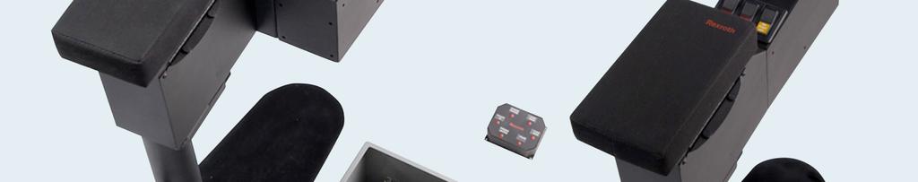
11 11/ Power Distribution Box The power distribution box contains 3 items: 1. The RC controller, which is the brains of your 140RC. 2. The Multiplexer board, which is responsible of allocating outputs to the function you want to control at any moment. 3. The Power Distribution board, which provides outputs for lighting functions and On/Off hydraulic functions. 16 channels 10A self-resettable fuse per channel LED indication Suppression diodes 100A MAX board output
12 12/17 3 Commissioning the CS-140 Each module of the CS-140 has its own unique commission procedure. 3.1 Armrest Module As these switches are concealed during normal operation, the lights to be operated by these switches are the lights the driver would need each time the truck is used for spreading and/or plowing. As the lighting functions are all operated via the power distribution unit, each light function should be tested individually. 3.2 Proportional Joysticks The minimum and maximum outputs should be set during the nulling process. The nulling procedure is explained on the next page. 3.3 Power Float Function The designated switch turns ON the Power Float function. The Power Float function will be active until you turn the switch off. If you raise the plow and return the joystick to the neutral position the plow will drop to the position set when the power float is on. This may be a rapid descent so care must be taken when the power float is active and you are making plow height adjustments. There is also an optional proximity switch that can be added to the circuit to automatically shut off the power float function when the plow is raised above a predetermined set point. For calibration of the Power-Float System, see the CS Power-Float Manifold Installation Manual. 3.4 Remote Pause The designated switch turns ON the Pause function, to deactivate the Pause function press the designated switch again. For all other Pause function settings see the controller Configuration Manual. 3.5 Low Oil Override To turn on the low oil override function press and hold the designated switch for the Low Oil Override function. Once the switch is depressed this function is deactivated Spreader Controller Module See the CS-440 Set-up Manual for the Configuration, Setup, Ground speed calibration and Material calibration procedures of the Function Switches Module As the lighting functions are all operated via the power distribution unit, each light function should be tested individually.
13 13/17 4 Nulling of the Joystick Outputs The Joystick movements are along an UP/DOWN Axis known as the Y-Axis, along a LEFT/RIGHT Axis known as X-Axis and along a twist LEFT/RIGHT axis known as the Z-Axis : Each Axis has 2 functions attached to it, thus the Y-Axis could be assigned the Plow Up/Down function as shown above and the X-Axis could be assigned the Plow Right/Left function as shown above. Let us assume the Z-Axis on this mode is not used. Mode switching is done using the Joystick Head switches or non-detent switches in the module. These switches have to be pressed once to activate the alternate function. All of the proportional joystick outputs need to be nulled and the sequence needs to be completed for each of the joystick functions. Both the minimum and the maximum output must be set for each of the Joystick functions. 4.1 Minimum Nulling Minimum Nulling is the process of eliminating Joystick movement required to overcome friction in the system to be activated as well as load the hydraulic cylinder to the point resulting in hydraulic cylinder movement.
14 14/17 NOTE: ALL OF THE FUNCTIONS LISTED BELOW MAY NOT BE CONFIGURED IN YOUR CS -140 DESIGN. NULL ONLY CONFIGURED APPLICATIONS. 1. Start the truck engine and operate the engine at 1500 RPM to ensure sufficient hydraulic oil flow. 2. Power up the controller. 3. Insert the programming key and turn clockwise ¼ turn. 4. Move the joystick in the direction of the function to be nulled. 5. When the desired minimum action of the function is observed, press the Min Key (arrow pointing towards switches). The output setting will be locked in. 4.2 Maximum Nulling Maximum Nulling is the process of setting the Joystick output to obtain the maximum desired speed of the hydraulic cylinder action. 6. Continue to slowly move the Joystick and observe the hydraulic cylinder extension speed. 7. When the desired maximum action of the function is observed, hold the Joystick at that position and press the Max Key (arrow pointing away from switches). The output setting and corresponding cylinder speed will be locked in. The process of nulling results in smooth, instantaneous response from the Joystick without delays caused by dead movement. 4.3 Nulling All Other Joystick Functions 8. Activate each of the other Joystick functions by pressing the switch for the mode you want to set and continue the nulling process for each function. As the Joystick for each function is moved the system will determine which function you are nulling. 9. Complete the minimum and maximum sequence for each function by repeating steps 4, 5, 6 and 7 above. 4.4 Clearing the Outputs (System Reset) To clear or reset the null settings back to the default settings. 1. Insert the programming key and turn clockwise ¼ turn. 2. Press both MIN and MAX buttons at the same time and hold for 2 3 seconds.
15 15/17 5 Emergency Raise Set-up This Emergency feature is pre-programmed for the user. To change the configuration, perform the following steps: 1. Switch into desired mode. 2. Insert the key and turn to go into programming mode. The emergency function can produce 2 simultaneous outputs. To set the first emergency output: 3. Move the joystick in the desired direction and press the emergency button. 4. Turn the key back to normal position to save your changes. To set the second emergency output: 5. Turn the key to go into programming mode again. 6. Move the joystick in the second desired direction and press the emergency button. 7. Turn the key back to normal position to save your changes.
16 16/17 6 Typical Connection Diagram
17 17/17 Notes:
Rexroth Controller Installation & Operations Manual
 Electric Drives and Controls Hydraulics Linear Motion and Assembly Technologies Pneumatics Service Rexroth - 105 Controller Installation & Operations Manual The Drive & Control Company Table of Contents:
CS 440RC. Solid De-icer Controller Detailed Configuration and Set-up Manual
 CS 440RC Solid De-icer Controller Detailed Configuration and Set-up Manual 2/57 Table of Contents 1 Overview 5 1.1 CS-440RC Front Layout 6 1.2 A Typical Solid De-icer (Salt/Sand) System 6 1.3 A Typical
DirectCommand Installation 5 Channel Spreader Control Module Technology
 DirectCommand Installation Ag Leader Technology Note: Indented items indicate parts included in an assembly listed above Part Name/Description Part Number Quantity Direct Command Kit 4100582 1 Cable Installation
RAM Rail Mount Kit RAM 201U 5 Arm RAM 2461U Monitor Mount RAM 235U Base, Double U-Bolt
 Note: Indented items indicate parts included in an assembly listed above Part Name/Description Part Number Quantity DirectCommand Kit 4100800 1 Cable Installation Kit 2000901-1 1 Dielectric Grease 2002872
INSTALLATION AND OPERATING INSTRUCTIONS DSST SYSTEM
 INSTALLATION AND OPERATING INSTRUCTIONS DSST SYSTEM PROPORTIONAL and NON-PROPORTIONAL TOGGLE SWITCH RADIO REMOTE CONTROL SYSTEM MODEL FHSTP/DSSTP SERIES FHST/DSST SYSTEM DESCRIPTION The DSST Wireless Control
RAM Rail Mount Kit RAM 201U 5 Arm RAM 2461U Monitor Mount RAM 235U Base, Double U-Bolt
 DirectCommand Installation Ag Leader Technology Note: Indented items indicate parts included in an assembly listed above Part Name/Description Part Number Quantity DirectCommand Kit 4100852 1 Cable Installation
CS 550/150RC. Spreader and Joystick Controller Calibration Manual
 CS 550/150RC Spreader and Joystick Controller Calibration Manual 2/38 Table of Contents 1 Programming Mode 3 2 Program Screen Layout 4 3 Changing Fields Data Entry 5 4 Initial Set-up 6 5 Ground Speed Calibration
CS 550/150 Symmetry. Spreader and Joystick Controller Calibration Manual
 CS 550/150 Symmetry Spreader and Joystick Controller Calibration Manual 2/29 Table of Contents 1 Programming Mode 3 2 Program Screen Layout 4 3 Changing Fields Data Entry 5 4 Initial Set-up 6 5 Ground
Ag Leader Technology. DirectCommand Installation RoGator Model Years
 Note: Indented items indicate parts included in an assembly listed above Part Name/Description Part Number Quantity Direct Command Kit 4100550 1 Dual Lock 2000052-9 1 Dual Lock 2000053-9 1 Hardware Kit
Ag Leader Technology. DirectCommand Installation Hardi 20-pin Interface Kit (Sprayer Chassis Mount)
") Part Name / Description Part Number Quantity DirectCommand Hardi Sprayer Kit 4100882 1 Dust Receptacle 8-pin 2002975-8C 1 Installation Instructions 2006335 1 Quick Reference Card- Liquid Application 2002831-38
Part Name / Description Part Number Quantity DirectCommand Hardi Sprayer Kit 4100882 1 Dust Receptacle 8-pin 2002975-8C 1 Installation Instructions 2006335 1 Quick Reference Card- Liquid Application 2002831-38
Draft sensor KMB series 30
 Draft sensor KMB series 0 RE 95170 Edition: 09.201 Replaces: 04.2012 Sensor for draft measurement Features Draft sensor according to Category rear three-point attachment (ISO 70-1) Sensor element with
DirectCommand Installation RoGator Model Year Ag Leader Technology
 Note: Indented items indicate parts included in an assembly listed above Part Name/Description Part Number Quantity Direct Command Kit 4100801 1 Dual Lock 2000052-9 1 Dual Lock 2000053-9 1 Quick Reference
Installation & Calibration Manual
 IMPORTANT NOTE: Please read first the HID ProxPoint Plus card reader information on the end of this manual referring to the programming method that is required to get the system up and running. RFID Proximity
Note: These installation instructions are only for the 4430/4440 Sprayer. For other SPX models please refer to P/N , &
 DirectCommand Installation Ag Leader Technology Note: These installation instructions are only for the 4430/4440 Sprayer. For other SPX models please refer to P/N 2005944, 2005945 & 2006383. Part Name/Description
SERVICE PARTS MANUAL
 SERVICE PARTS MANUAL 8 SERIES SNOW PLOW FOR SERIAL NUMBERS AFTER 8D100000 00 Sno-Way International 9100G TABLE OF CONTENTS PAGE DEFLECTORS... POWER PACK... HYDRAULIC POWER UNIT... LIFT CYLINDER... ANGLE
DirectCommand Installation Hardi Spray Box II 39-pin Kit. Ag Leader Technology. PN: Rev. E January 2014 Page 1 of 16
 DirectCommand Installation Ag Leader Technology Note: Indented items indicate parts included in an assembly listed above Part Name/Description Part Number Quantity Direct Command Kit 4100532 1 Cable Installation
Installation Instructions
 Installation Instructions (1771-ODD Series B) Use this document as a guide when installing the catalog number 1771-ODD series B output module. The ac isolated output module is shipped in static-shielded
AL101A1A Joystick Controller for Operating a Snow Plow
 AL101A1A Joystick Controller for Operating a Snow Plow page Modes of operation, Deadman, Float 2 Program mode, unlock 3 Program address list, settings, ranges, presets 4 Wiring connections, joystick 5
DirectCommand Installation CASE IH SPX Ag Leader Technology. PN: Rev. E January 2014 Page 1 of 19
 Note: These installation instructions only cover installation on SPX 4420 Sprayers only. For installation on SPX 3230/3330 Sprayers refer to Installation Instructions P/N 2005945. For SPX 4430 refer to
Tile Plow Installation O Connell
 NOTE: Indented items indicate parts included in an assembly listed above Part Name/Description Part Number Quantity Tile Plow Kit O Connell System 4100471 1 Hex head cap screw 3/8-16 x 3 2002003-38300
Digital Proportional Valve Amplifier
 Digital Proportional Valve Amplifier The Amplifier is a compact, low profile DIN mounted controller for use with proportional solenoid valves. The provides current to a valve coil in proportion to an input
Quick Start Guide. SEB-710 I/O Expansion board. Introduction
 SEB-710 I/O Expansion board Revision 1.0 - (March, 2011) Saflec Systems (Pty) Ltd Quick Start Guide Introduction The SEB-710 is an I/O expansion device for additional inputs and outputs. It has eight relay
Magnum Club Smoke System
 AND INSTALLATION VERSION.0 Martin Professional A/S,Olof Palmes Allé 8, DK-800,Aarhus N Phone: +45 87 40 00 00 Internet: www.martin.dk Magnum Club Smoke System Fluids Suitable for this system: CONNECTIONS
Tile Plow Installation Gold Digger
 NOTE: Indented items indicate parts included in an assembly listed above Part Name/Description Part Number Quantity Tile Plow Kit Soil Max System 4100470 1 Hex head cap screw - M10 x 75mm 2002007-10075
Instruction book IQAN-LSL. Publ no HY /UK Edition 0301
 Instruction book IQAN-LSL Publ no HY17-8367/UK Edition 0301 Contents 1 Introduction......................................................2 2 Precautions.......................................................3
Model: CAM430MV Wired Multi-View Camera with License Plate / Rear Surface Mount Installation Manual Features
 Model: CAM430MV Wired Multi-View Camera with License Plate / Rear Surface Mount Installation Manual Features Fully Adjustable, Multiple Viewing Angle Smart Camera. High Resolution, 1/2 CMOS Color Camera
Ag Leader Technology. DirectCommand Installation Miller Nitro 5000 & 6000 ISO Kit
 Note: Indented items indicate parts included in an assembly listed above Part Name/Description Part Number Quantity Direct Command Miller N5/5000 Series Kit 4200179 1 Installation Instructions 2006382
Ag Leader Technology Insight. Direct Command Installation Spra-Coupe 7000 Series
 Note: Indented items indicate parts included in an assembly listed above. Part Name / Description Part Number Quantity Direct Command Spra-Coupe 7000 Kit 4100531 1 Liquid Product Control Module 4000394
Control system MultiDrive 2 with D3 joysticks
 means total control Control system MultiDrive 2 with D3 joysticks Technical description Control system MultiDrive 2 with D3 joysticks D3 joysticks and Display... Driver display With their comfortable pistol
DirectCommand Installation RoGator 864/874/1064/1074 (MY 2006 & Earlier) Ag Leader Technology
 Ag Leader Technology") Note: Indented items indicate parts included in an assembly listed above Part Name/Description Part Number Quantity Direct Command Kit 4100524 1 Generic Cable Installation Kit 2000901-1 1 Hardware Kit
Note: Indented items indicate parts included in an assembly listed above Part Name/Description Part Number Quantity Direct Command Kit 4100524 1 Generic Cable Installation Kit 2000901-1 1 Hardware Kit
MODEL K INSTRUCTION MANUAL CONTENTS
 MODEL 7173 - K INSTRUCTION MANUAL CONTENTS 1. MODEL 7173 - K ELECTRONIC FFU STEERING SYSTEM 2. MODEL 7173 - K COMPONENTS 3. MOUNTING THE 7173 - K AMPLIFIER UNIT 4. MOUNTING THE FFU CONTROLLER UNITS 5.
Diagnostics of Genie / Sauer Danfoss Joystick Controllers Deutsch type connection
 Diagnostics of Genie / Sauer Danfoss Joystick Controllers Deutsch type connection Tools needed: Multi-meter Small Screwdriver Harness Adaptor 119613 Jumper Wires w/clips Three 1.5 volt AA or AAA Batteries
INTELLIGENT DOCKING STATION USERS MANUAL
 Kodiak Mobile by Jotto Desk 209 W. Easy St., Rogers, AR USA 72756 Customer Service: 877.455.6886 http://www.kodiakmobile.com PART NUMBER: 450-4011 - Last Update: 06.2009 INTELLIGENT DOCKING STATION USERS
Installation & Calibration Manual
 Installation & Calibration Manual ScanWeight (System with Bluetooth module) ScanWeight-RF (System with Bluetooth and RF module) Lift Truck Onboard Check Weighing Initiated by Barcode Scanner ScanWeight
Electronic Control Unit RC
 Industrial Hydraulics Electric Drives and Controls Linear Motion and Assembly Technologies Pneumatics Service Automation Mobile Hydraulics Electronic Control Unit RC RE 900/.0 /6 Replaces: 09.0 Series
Cab Box Kit Dome Plug Cab Box Cab Box Lid
 DirectCommand Installation Ag Leader Technology Note: Indented items indicate parts included in an assembly listed above Part Name/Description Part Number Quantity Direct Command Kit 4100578 1 Cable Installation
SERVICE PARTS MANUAL
 SERVICE PARTS MANUAL DX SERIES SNOW PLOW FOR SERIES SNOW PLOWS SERIAL NUMBERS AFTER DX0000 00 Sno-Way International 0G TABLE OF CONTENTS Page HYDRAULIC SYSTEM (DX)... POWER PACK FRAME... 3 BLADES... LIFT
ivisibility (Keypad Operator Access Control Series) Lift Truck Onboard Automatic Detection / Recording of All Operational Downtime Events
 Lift Truck Onboard Automatic Detection / Recording of All Operational Downtime Events") Installation & Operational Manual ivisibility (Keypad Operator Access Control Series) Lift Truck Onboard Automatic Detection / Recording of All Operational Downtime Events ivisibility V2 General Installation
Installation & Operational Manual ivisibility (Keypad Operator Access Control Series) Lift Truck Onboard Automatic Detection / Recording of All Operational Downtime Events ivisibility V2 General Installation
Model HM-535 Power Supply Installation and Service Instructions
 Model HM-535 Power Supply Installation and Service Instructions 430-535 0104 2004 Heritage MedCall, Inc SENTRY INSTALLATION & SERVICE INSTRUCTIONS POWER SUPPLY UNIT Model HM-535 IMPORTANT SAFETY INSTRUCTIONS
RT02 Series Robust Industrial Joystick. RunnTech
 Electronics (Changzhou) Corp. RT0 Series Robust Industrial Joystick RT0 Series Robust Industrial Joystick Product Features Potentiometer sensor or Hall sensor; Single axis, dual axis or axis control; Resistant
Installation & Calibration Manual
 Installation & Calibration Manual UT SkidWeigh Plus Series Lift Truck Onboard Check Weighing System With Monitoring Of All Operational Idling Times Automatic Idling Times Notification Within Specific Utilization
INSTRUCTION MANUAL VOLTAGE REGULATOR MAXBEC2D PLUS EX
 VOLTAGE REGULATOR MAXBEC2D PLUS EX Released by JETI model s.r.o. 29. 10. 2014 CONTENT 1. INTRODUCTION... 3 2. DESCRIPTION... 4 2.1 MAXBEC2D PLUS... 4 2.2 MAGNETIC SWITCH... 4 2.3 RC SWITCH... 5 3. CIRCUITS...
Installation and Hardware Guide
 Helios W.E.S. 1000 & 2000 (Wireless Emergency Stop) Installation and Hardware Guide E5, Version 1.3 Helios Global Tech Ltd. Contact Information Helios Global Technologies 1920 Windsor Rd Kelowna BC V1Y
Position sensor PO1 series 20
 Position sensor PO1 series 20 RE 95160 Edition: 09.2013 Replaces: 03.2012 Inductive sensor for position measurement Features Axially moving button with spring preload Inductive element according to the
Software... pg3 File Maintenance Training
 V-MUX Installation Practices March 2010 1 V-MUX Installation Practices Software...... pg3 File Maintenance Training Electrical...... pg3 Circuit breakers or Fuse protection 3 Power to Nodes 3 Ground to
VR2 R-NET LED R-NET LCD. Controller System Operation
 VR2 R-NET LED R-NET LCD Controller System Operation 1.VR2 Controller Operation 1.1 Controls/JSM 1.2 Button/Indicator 1.3 Control System Status indication 1.4 Module Wiring 1.5 VR2 Locking / Unlocking The
Load Pins Custom Build Load Pins
 Features Load Pins Custom Build Load Pins 0.5-500Te capacities available. Overload 200% of rated capacity. Ultimate breaking load >500% of rated capacity. Temperature compensated wheatstone bridge. Stainless
TARA CONTROLS AGC-5. UCI Random Start USER S GUIDE. With Optional Warning Flashes for the Hearing Impaired. TARA CONTROLS by Cartessa Corporation
 TARA CONTROLS AGC-5 UCI Random Start USER S GUIDE With Optional Warning Flashes for the Hearing Impaired TARA CONTROLS by Cartessa Corporation 4825 Cincinnati-Brookville Road Shandon, Ohio 45063 Phone:
Ag Leader Technology. DirectCommand Installation Rogator 900/1100/1300 Sprayers
 DirectCommand Installation Ag Leader Technology Note: Indented items indicate parts included in an assembly listed above Part Name/Description Part Number Quantity DirectCommand Kit 4100876 1 Quick Reference
Precautions. Please read carefully before using this product.
 Thank you for purchasing this BEWITH Mirror Media MM-1. It is designed to give you many years of enjoyment. Please read all instructions in this manual before attempting operation and keep it handy for
AS7.P CF20 NPT DOCK AS7.P CF20 DPT DOCK AS7.P CF20 NPT DOCK WITH SCREEN LOCK AS7.P CF20 DPT DOCK WITH SCREEN LOCK AS7
 AS7.P020.100 CF20 NPT DOCK AS7.P020.102 CF20 DPT DOCK AS7.P020.200 CF20 NPT DOCK WITH SCREEN LOCK AS7.P020.202 CF20 DPT DOCK WITH SCREEN LOCK AS7.P020.001 CF20 SCREEN LOCK ARM PANASONIC TOUGHBOOK CF20
DirectCommand Installation DirectCommand Complete Wiring Harness
 Note: Indented items indicate parts included in an assembly listed above Part Name/Description Part Number With Switch Box Quantity by Model With Boom Switch Cable Display Cable Kit 4100814 1 1 Power Control
Haze 800 DMX. User Guide. English
 Haze 800 DMX User Guide English Introduction Box Contents Haze 800 DMX Remote Control (wired) User Guide Safety & Warranty Manual Support For the latest information about this product (documentation, technical
Quick Start Installation Guide
 apc/l Quick Start Installation Guide Version A2 Document Part Number UM-201 May 2010 OVERVIEW The apc/l is an intelligent access control and alarm monitoring control panel which serves as a basic building
INSTALLATION INSTRUCTIONS FOR THE MINI-KEY SYSTEM. Doc Rev B
 INSTALLATION INSTRUCTIONS FOR THE MINI-KEY SYSTEM Doc. 6001051 Rev B Page 2 of 7 Doc 6001051 Rev B IMPORTANT NOTICES The Mini-Key system is a very reliable and easy to use system. However, damage could
D115 The Fast Optimal Servo Amplifier For Brush, Brushless, Voice Coil Servo Motors
 D115 The Fast Optimal Servo Amplifier For Brush, Brushless, Voice Coil Servo Motors Ron Boe 5/15/2014 This user guide details the servo drives capabilities and physical interfaces. Users will be able to
Energy Management System. Operation and Installation Manual
 Energy Management System Operation and Installation Manual AA Portable Power Corp 825 S 19 TH Street, Richmond, CA 94804 www.batteryspace.com Table of Contents 1 Introduction 3 2. Packing List 5 3. Specifications
Kodiak Mobile INTELLIGENT DOCKING STATION USERS MANUAL PART NUMBER: PANASONIC CF53 TOUGHBOOK COMPATIBLE AN ISO 9001:2008 CERTIFIED COMPANY
 CUSTOMER SERVICE If you have any questions or require additional information please contact Customer Service at 877-455-6886, Monday though Friday, 8:00am - 5:00pm CST. TECHNICAL SUPPORT Kodiak Mobile
Part Name/Description Part Number Quantity
 Part Name/Description Part Number Quantity Direct Command Kit 4100883 1 Installation Instructions 2006336 1 Hardware Kit Large Module 2001354-1 2 Cable Installation Kit 2000901-1 1 Quick Reference Card
What s in the Box? REAR VIEW SAFETY
 TM 1 What s in the Box? 1 Full HD Color Infra-red Weather Proof Camera 1 Full HD 7" TFT LCD Color Monitor w/monitor Mount 1 Power Harness 1 66 Camera Cable 1 Power Connection Wire 1 Screw Kit for installation
Installation Instructions
 Alliance Arming Station AL-1111, AL-1116 1048520C September 2006 Copyright 2006, GE Security Inc. Introduction This is the GE Alliance Arming Station for models AL-1111 (four-line LCD) and AL-1116 (four-line
Part 2: Building the Controller Board
 v3.01, June 2018 1 Part 2: Building the Controller Board Congratulations for making it this far! The controller board uses smaller components than the wing boards, which believe it or not, means that everything
Integrated Video Camera Installation Guide
 Integrated Video Camera Installation Guide Always mount the camera in an area cleaned by the wiper travel, and within the top 2 inches of the wiper sweep area on heavy trucks. You will need a PH0/1 size
LINEAR ACTUATOR CONTROL Use with NEW LEADER 7 manual
 MANUAL FOR MODEL LINEAR ACTUATOR CONTROL Use with NEW LEADER 7 manual INSTALLATION OPERATION TROUBLESHOOTING PARTS LIST This unit may have been built with SPECIAL FEATURES. Provide SERIAL NUMBER when ordering
xtablet T1600 Vehicle Holder Installation Guide
 This document will step you through setting up the T1600 Vehicle Holder installation and tips for a safe, clean and long lasting installation. Preparing to Mount the Vehicle Holder Warning : Dock mounting
PLUS+1 GUIDE Software. JS6000 PWM Service Tool User Manual
 PLUS+1 GUIDE Software JS6000 PWM Service Tool TEMP 1 6 1 6 12 7 12 7 About this Manual Organization and Headings To help you quickly find information in this manual, the material is divided into sections,
MicroTech III Water Source Heat Pump BACnet MS/TP Communication Module
 Installation and Maintenance Manual IM 928- Group: Controls Part Number: 66920770 Date: July 2009 Supersedes: IM 928 MicroTech III Water Source Heat Pump BACnet MS/TP Communication Module NOTICE Use this
REMOTE THROTTLE. FOR CUMMINS CELECT and CELECT+ ENGINES SERIES M11, N14, L10 MODEL : RTU 1 OPERATING INSTRUCTIONS IDLE SETTING RTU
 REMOTE THROTTLE FOR CUMMINS CELECT and CELECT+ ENGINES SERIES M11, N14, L10 MODEL : RTU 1 OPERATING INSTRUCTIONS PRESET FRC IDLE INCREASE s 1200 SETTING s DECREASE RTU FIRE RESEARCH CORP. 26 Southern Blvd.,
 18/04/2013 Ins-30169 Net2 PaxLock Mifare Paxton Technical Support 01273 811011 support@paxton.co.uk Technical help is available: Monday - Friday from 07:00-19:00 (GMT) Saturday from 09:00-13:00 (GMT) Documentation
InSight Single Implement
 Note: Indented items indicate parts Included in an assembly listed above Part name/description Part Number Quantity DirectCommand 4100544 1 Cable Install Kit 2000901-1 1 Module Mounting Plate Kit 2001358
TABLE OF CONTENTS. Safety Notices... 1
 TABLE OF CONTENTS Safety Notices... 1 System Overview... 3 Virtual Terminal (VT)... 3 Master Switch... 4 Working Set Master (WSMT) Module (Granular Fertilizer Control)... 4 Working Set Member (WSMB) Module
NNG-Ford V1 NTV-KIT558. Navigation interface for FORD vehicles equipped with 8.4 MyTouch NTV-DOC218
 3950 NW 120th Ave, Coral Springs, FL 33065 TEL 561-955-9770 FAX 561-955-9760 NNG-Ford V1 Navigation interface for FORD vehicles equipped with 8.4 MyTouch NTV-KIT558 NTV-DOC218 SoftTouch Navigation System
Ag Leader Technology. DirectCommand Installation GVM Cab Kit (MY 2007 and Up) Important Notices
 Important Notices") Note: Indented items indicate parts included in an assembly listed above Part Name/Description Part Number Quantity Direct Command Kit 4100579 1 Cable Installation Kit 2000901-1 1 Dust Plug Deutsch 12
Note: Indented items indicate parts included in an assembly listed above Part Name/Description Part Number Quantity Direct Command Kit 4100579 1 Cable Installation Kit 2000901-1 1 Dust Plug Deutsch 12
CS 550/150RC. Frequently Asked Questions (FAQs)
") CS 550/150RC Frequently Asked Questions (FAQs) 550 FAQ S Electronic Controller 1. How to diagnose system and sensors? 2. Select Driver ID 3. Define a custom driver ID for AVL operation 4. Select operation
CS 550/150RC Frequently Asked Questions (FAQs) 550 FAQ S Electronic Controller 1. How to diagnose system and sensors? 2. Select Driver ID 3. Define a custom driver ID for AVL operation 4. Select operation
GENERIC. CANbus Setup / Configuration Manual. R170 Receiver. Revised May 17, Version 3 DMAN
 GENERIC CANbus Setup / Configuration Manual R170 Receiver Revised May 17, 2006 Version 3 DMAN - 2866-01 #74-1833 Coast Meridian Road, Port Coquitlam, BC, Canada V3C 6G5 Ph# (604) 944-9247 Fax# (604) 944-9267
Rheinmetall Elektronik
 PAT America, Inc. Rheinmetall Elektronik DS350 MODULAR BOOM CONTROL EXTENSION FOR GROVE CRANE TMS/TTS 870 TROUBLESHOOTING MANUAL P/N 031-300-190-061 Rev. B 02/12/01 NOTICE The information in this document
Temperature Programming Quick Reference Guide
 Temperature Programming Quick Reference Guide Normal Mode Dial Brightness (press one at a time) Peak Mode Factory Default Reset (Hold for 5 seconds) High Alert Setting Mode Use LEFT or RIGHT buttons to
AE2400 Series Installation Guide
 AE2400 Series Installation Guide GENERAL INFORMATION This document contains information for installing the Mars Electronics AE2400 Series Bill Acceptor. This Bill Acceptor is designed to fit into the standard
MicroTech III Applied Terminal Systems BACnet MS/TP Communication Module
 Installation and Maintenance Manual IM 928-2 Group: Controls Part Number: 669207702 Date: March 2011 Supersedes: IM 928-1 MicroTech III Applied Terminal Systems BACnet MS/TP Communication Module NOTICE
Cheap Control Systems. Cheap Six Channel (C6C) Servo Controller Version 2.3 OVERVIEW
 Servo Controller Version 2.3 OVERVIEW") Cheap Control Systems Cheap Six Channel (C6C) Servo Controller Version 2.3 The Cheap Six Channel (C6C) Servo Controller is a low cost embedded controller that allows the Sony Playstation 2 (PS2) game pad
Cheap Control Systems Cheap Six Channel (C6C) Servo Controller Version 2.3 The Cheap Six Channel (C6C) Servo Controller is a low cost embedded controller that allows the Sony Playstation 2 (PS2) game pad
RT300 Series Crane & Hoist Joystick. RunnTech. Potentiometer: ±32, Hall sensor: ±20
 Electronics (Changzhou) Corp. RT00 Series Crane & Hoist Joystick RT00 Series Crane & Hoist Joystick Product Features Single axis or dual axis control; Pure silver contacts to ensure durable; Spring return
Elapsed Timer Control Panel
 Installation Manual V6.2 Elapsed Timer Control Panel Current as of August 2017 The Sapling Company, Inc. Elapsed Timer Control Panel Table of Contents Table of Contents 2 Important Safety Instructions
Application Engineering B U L L E T I N. AE R1 November Intelligent Store Discus V1.0 Operators Manual
 Application Engineering B U L L E T I N AE8-1337 R1 November 2006 Intelligent Store Discus V1.0 Operators Manual The Intelligent Store Discus product line has recently been introduced on 2D, 3D, and 4D
Miller Nitro 4000 Series
 Miller Nitro 4000 Series ISO Liquid Kit PN: 2006466 REV. A Table of Contents Introduction... 3 Important Information... 3 Preliminary Installation Requirements... 3 Trademark... 3 Technical Support...
BODAS DCT Display Configuration Tool
 BODAS DCT Display Configuration Tool RE 95271/03.12 1/6 Replaces: 07.07 Data sheet PC-Software, Version 1.0 and 2.0 Graphic configuration tool for BODAS display DI3 Contents Ordering code 2 Required components
Sidewinder Pumps Inc. AC Timer/Controller
 Sidewinder Pumps Inc. AC Timer/Controller Page 1 of 12 Rev 032417 Table of Contents 1. Warnings-------------------------------------------------------------------------------------------------- 3 1.1.
Digital Dash I/O Adapter Configuration
 Digital Dash I/O Adapter Configuration The I/O Adapter adds ten inputs/outputs to the 7 digital dash. These inputs and outputs can then be configured as gauges or switches, and data logged locally through
TCNM-ACBB1 Installation Manual
 The TCNM-ACBB1 is a connection box that can be used as an accessory to facilitate system connections for installation and device replacement of several Banner family reading devices. System cabling is
Applications of Programmable Logic Controllers DG31 34
 Applications of Programmable Logic Controllers DG31 34 Purpose Unit purpose: This Unit is designed to introduce candidates to Programmable Logic Controllers (PLCs) and enable them to understand how PLCs
Planning the installation:
 INSTALLATION MANUAL T he installation of Vektor MAX is easy and quick. The system consists in a single unit with all the electronics embedded, plus a light-bar for guidance and a high gain GPS/GLONASS
Trouble Shooting Leveling Control Box Electric Jacks. Touch Pad LED Probable Cause Solution
 Trouble Shooting Leveling Control Box 140-1224 Electric Jacks Copyright Power Gear Issued: January 2013 #82-L0524, Rev. OA Touch Pad LED Probable Cause Solution 1. On/Off LED will not light 2. Wait LED
Documentation on all Paxton products can be found on our web site -
 02/23/2012 Ins-30168-US Net2 PaxLock Paxton Technical Support 1.800.672.7298 supportus@paxton-access.com Technical help is available: Monday - Friday from 02:00 AM - 8:00 PM (EST) Documentation on all
AX1500. Dual Channel Digital Motor Controller. Quick Start Manual. v1.9b, June 1, 2007
 AX1500 Dual Channel Digital Motor Controller Quick Start Manual v1.9b, June 1, 2007 visit www.roboteq.com to download the latest revision of this manual Copyright 2003-2007 Roboteq, Inc. SECTION 1 Important
Innovation First, Inc Full-Size Robot Controller Reference Guide
 2004 Full-Size Robot Controller Reference Guide 2.19.2004 www.innovationfirst.com Page 2 Table of Contents 1. Robot Controller Overview... 3 2. Main Power Input... 4 3. Battery Backup Power... 4 4. PROGRAM...
Roof Truss Roller Press, Tables and Jigging
 RoofTracker II Roof Truss Roller Press, Tables and Jigging August 2015 Page 1 Table of Contents Equipment Introduction to the Equipment Restricted Zone Truss Terminology Parts of a Truss Important Notes
INSTALLATION MANUAL. MEC-HL COMPACT Electromechanical proportional actuators for Hydraulic Applications
 INSTALLATION MANUAL MEC-HL COMPACT Electromechanical proportional actuators for Hydraulic Applications Table of Contents Legal Disclaimers, Copyright, Disclaimer, Safe system use, Customer Service Contact
EV Controls user Guide
 EV Controls user Guide Copyright EV Controls Table of Contents Introduction... EV Controls System Features... General guidelines for installation... Inverter Electrical Pinout Sheet... Drive Inverter Connections...
EVERSAN. Instruction Manual MODEL 9007/9008 TENNIS SCOREBOARD. Address: 34 Main Street, Whitesboro, NY 13492
 MODEL 9007/9008 TENNIS SCOREBOARD Instruction Manual Address: 34 Main Street, Whitesboro, NY 13492 Phone: 315-736-3967 Toll Free: 800-383-6060 Fax: 315-736-4058 SCOREBOARDS TIMERS MESSAGE SIGNS VIDEO DISPLAYS
PowerCore Model TEC-10 Installation Manual
 PowerCore Model TEC-10 Installation Manual Products covered in this document comply with European Council electromagnetic compatibility directive 2014/30/EU and electrical safety directive 2014/35/EU.
Overview Included in the Box: Pinout Installation Power Supply Stepping Motors DIP Switch (JP1) Location...
 Location...") DRV7 USERS GUIDE Overview... 3 Included in the Box:... 4 Pinout... 4 Installation... 5 Power Supply... 6 Stepping Motors... 8 DIP Switch (JP1) Location... 9 Setting the Output Current (JP1)... 9 Microstep
DRV7 USERS GUIDE Overview... 3 Included in the Box:... 4 Pinout... 4 Installation... 5 Power Supply... 6 Stepping Motors... 8 DIP Switch (JP1) Location... 9 Setting the Output Current (JP1)... 9 Microstep