DISCOVER CONTROL IDE
|
|
|
- Irene Boyd
- 6 years ago
- Views:
Transcription

1 DISCOVER CONTROL IDE Visual Logic Programmer... 3 Main window... 3 Logic parameters... 3 Functional blocks... 4 Inputs... 4 Outputs... 4 Constants... 5 Variables... 5 Creating program... 5 Emulator... 8 Online mode... 8 Quick example... 9 Visualization Tool...17 HMI concept...18 Main window...18 Widgets...19 Analog widgets...20 Show value...20 Bar graph...22 Gauge...24 Digital Widgets...26 Command Widgets...27 Command...28 Set value
2 Sounds...30 Device variables...31 STANDALONE HMI...32 DC PowerStream PLC...33 Power Supply...35 Default IP address...35 Digital inputs...36 Analog inputs...36 Digital outputs...37 Factory reset...38 Appendix A

3 Visual Logic Programmer Main window The VLP have a one main window with a horizontal and vertical toolbar. Each button has its tooltip. Also there is console section for error and warning messages, expansion box for device properties and adding menu. Logic parameters On the right side of the VLP window is located properties expansion box. On this menu user can choose between using Emulator or real physical device. If the user chose physical device, below this chooser is located an IP address button. Also the common parameter for both configurations is Device scan time. On this button user can set PLC sampling period. The value is in range from 0ms to up. The very low 3
4 value may not be achieved, and depend of the program structure and size. The common value in industry is 200ms. Also there is a field to set device PIN. The Device PIN is a secret string that allows communication with a device. Only the owner of the right PIN can program, read and set data to PLC. Every device has its own PIN. The PIN is there to protect your system if your device is available from internet. Functional blocks Blocks are the elements from which the VLP software builds program. You can program PLC by creating and interconnecting blocks in appropriate ways. All Functional blocks have inputs and outputs. They can have two types B (as logical Boolean) and I (as integer). The descriptions of blocks supported on device see in (Appendix A) Inputs From the input expansion box on the left side, user can choose digital or analog inputs by drag & drop to drawing area. There are 8 digital and 4 analog inputs. Emulator can support this number of inputs but for the physical device it depends on the device model. Inputs are enumerated from 0 to 7 and 0 to 3. Digital inputs value is [0, 1] and analog has value in range [0, 1024]. In online mode all inputs can be decupled and simulated. Outputs From the output expansion box on the left side, user can choose digital outputs by drag & drop to drawing area. There are 8 digital outputs. The Emulator can support this number of outputs but for the physical device it depends on the device model. Outputs are enumerated from 0 to 7. Digital output value is [0, 1]. In online mode all outputs can be decupled and simulated see chapter 4. 4
5 Constants Creating constants is available from popup menu or from button on the vertical toolbar. Constants values are in range [ , ]. Number of constants is limited by PLC type from 32 to up. Variables Variables are parts of memory that can be written or read from program diagram. They are created by user. They are represented like inputs or outputs if they are used to read value or to store value. Also they can by read or set by other application and programs from communication ( HMI, SCADA ). Number of variables is limited by PLC type from 32 to up. All variables are of type (I) and in range of [ , ]. Creating program The main goal of VLP is to provide easy programming without knowledge for procedural programming languages and also to visualize process on the PLC. By adding functional blocks and connecting outputs and inputs, user can create the desired process flow chart. The main features of this type of PLC programming are named as Function Block Diagram. A Function Block Diagram (FBD) is a block diagram that describes a function between input variables and output variables. A function is described as a set of elementary blocks. Input and output variables are connected to blocks by connection lines. An output of a block may also be connected to an input of another block. Inputs and outputs of the blocks are wired together with connection lines, or links. Single lines may be used to connect two logical points of the diagram: An input variable and an input of a block An output of a block and an input of another block An output of a block and an output variable The connection is oriented, meaning that the line carries associated data from the left end to the right end. The left and right ends of the connection line must be of the same type. 5
 or a")
6 Multiple right connections, also called divergence can be used to broadcast information from its left end to each of its right ends. All ends of the connection must be of the same type. Figure 1 Function block diagram is one of five languages for logic or control configuration supported by standard IEC for a control system such as a Programmable Logic Controller (PLC) or a Distributed Control System (DCS). After successfully creating program and setting parameters on the button on horizontal too bar, user can create Power Stream program and download to Emulator or physical device. In case there is any error, this button will be disabled. If target device is Emulator the VLP will automatically start it. If the PowerStream is properly downloaded to the device or emulator and started the VLP will play short beep signal and appear message box. If something is wrong, the VLP will play deep horn sound and appear message. 6

7 Figure 2 Figure 3 7

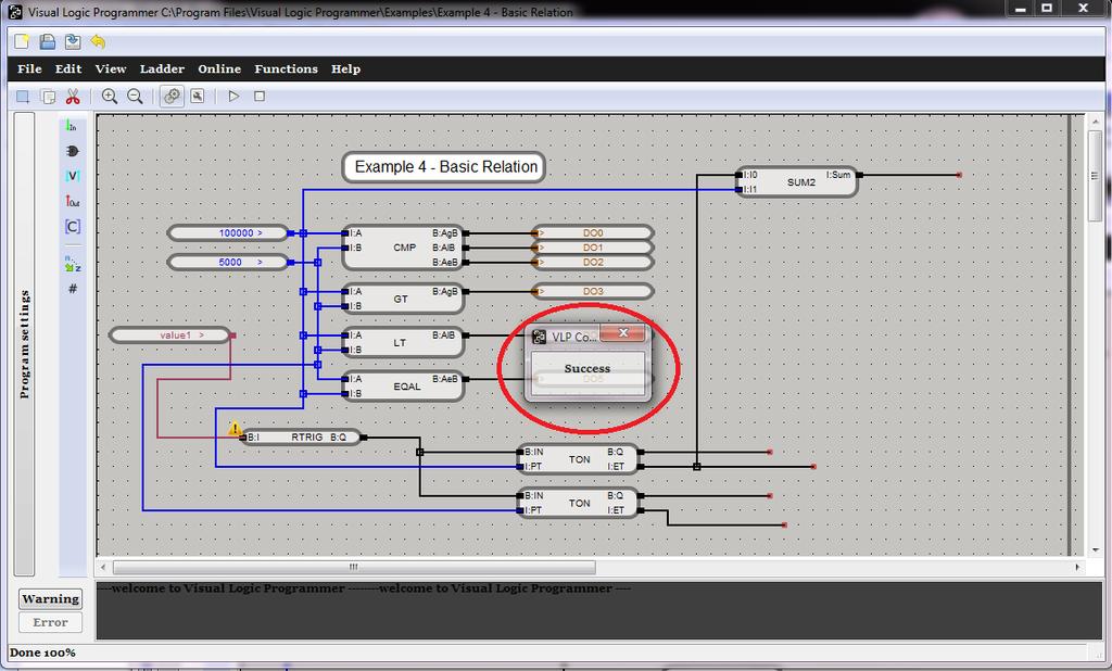
8 Emulator The Discover Control provides software emulator of physical device. Emulator is fully compatible with physical device. In other words the user can fully make the project, and test it, simulate all inputs and outputs. User has to select emulator as target. Online mode Online mode provides full monitoring of current process on the physical device. Also with options of decupling inputs and setting simulated values the user can simulate any physical process in order to test and debug program. When the device is running the user can monitor process any time, if user has a proper project file. If the project file is not the same as program on the device the VLP, online mode will not work properly. To prevent this, the VLP will compare the project file and program on the device before running online mode and alert user whether something is wrong. To go to online mode user needs to open proper project file and to choose target device (PLC or Emulator). Next just press Play button on horizontal toolbar. 8
9 Figure 4 If everything is correct the background of VLP will change color in green or yellow depending whether device or emulator is in use. Otherwise the user will get notice that there is communication error or mismatch. Now VLP is in online mode. Each connection between functions inputs and outputs are colored in blue or red. Each connection has its own value. The line is blue when value is 0 otherwise is red. In online mode the user can edit diagram only allow actions are zoom in and zoom out, stop online mode, and decupling inputs outputs and setting values to its and to variables. Decupling inputs is features of Power Stream to cut out all physical signal information and to allow to user to set the value what is need. Next the PLC will continue to workout with new forced value until the user couple its input or device reset. In implementation job or testing this feature is wary power full. This is providing by right click to input (digital or analog) Digital outputs have the same features as inputs the user can decupled output from value that is currently calculate in ladder an force what is need. Quick example I Start VLP II Set device IP and scan time Click on the vertical button Program Settings Click on the button Device IP address to set device IP (not required if use Emulator) Click on the button Device scan time to set program scan time 9


10 III Add digital inputs Click on the button in the vertical tool bar to expand input menu Select desired input drag & drop to droving area 10


11 IV Add functional blocks Click on the button in the vertical tool bar to expand block menu Select desired input drag & drop to droving area 11
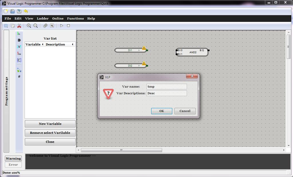
 In the dialog entry Var Descriptions type hint or description After creating variable just drag & drop to droving area To set value to variable choose Assign Var, to")
12 V Create a new variable Click on the button to in the vertical tool bar to expand input menu To create new variable click on New Variable In the dialog entry Var name type desired name (no special carcters, no space use _ instead) In the dialog entry Var Descriptions type hint or description After creating variable just drag & drop to droving area To set value to variable choose Assign Var, to read value use Read Var 12

13 13


14 VI Add outputs Click on the button to in the vertical tool bar to expand output menu Select desired output and just drag & drop to droving area VII Connecting diagram Point mouse on the output of block left click and move to another block input and release mouse button 14


15 VII Sort Create Download and Start Online Click on the sort button to sort functional blocks execution order Chose target device or emulator Save Build and download to target Go to on line mode 15


16 VIII Force inputs Right click on the input Click on the Decouple/Coupled to decuple or couple Click on the On/Off to set value 16
17 Visualization Tool 17
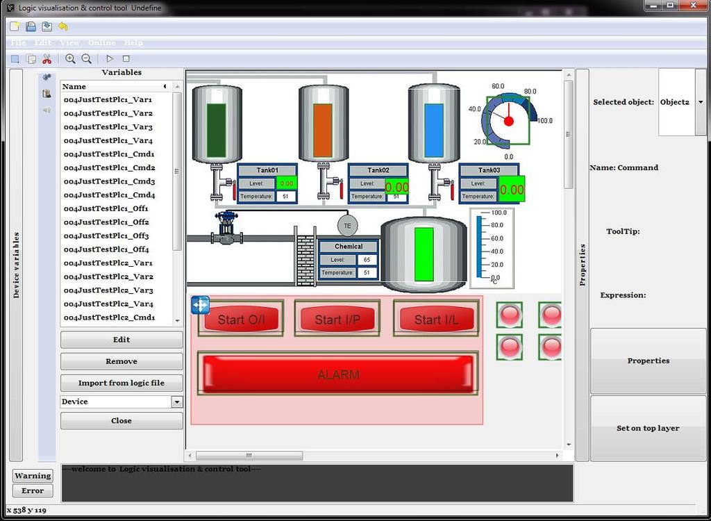
18 HMI concept A human machine interface or HMI is the apparatus which presents process data to a human operator, and through which the human operator controls the process. The HMI package for the SCADA system typically includes a drawing program that the operators or system maintenance personnel use to change the way these points are represented in the interface. These representations can be as simple as an on-screen traffic light, which represents the state of an actual traffic light in the field, or as complex as a multi-projector display representing the position of all of the elevators in a skyscraper or all of the trains on a railway. The DC VT is two in one visualization tool and standalone executive HMI. Main window The VT has a one main window with horizontal and vertical toolbar. Each button have own tool tip. Also there are console section for error and warning messages, expansion box for device manager, adding menu and picture properties. On the figure (1) is explained all buttons and sections. 18

19 Main window VT Widgets The VT has two types of widgets active and passive. The active widgets are dynamically change their appearance depending of their type and expression that is assigned to them on the another side the passive widgets are only icons that use to improve visual appearance. Active widgets have tree main categories analog, digital and commands. All widgets have the common features: size, position.. 19
20 Analog widgets Analog widgets are using to represent the values from process in tree ways, as number value, as bar graph and as gauge. As all others widgets they use espressinon made from variables of target device to manage their appearance. Show value Show value is rectangular form with numerical label inside. This string is a current value of assigned expression. The features of Show value are: Position on the screen Dimension Color of the rectangular background (can be transparent) Color of the numerical label Expression Tooltip label To add show value to drawing area just drag&drop from active widgets expansion menu sub menu analog. To format widget right click and choose properties. 20

21 Adding Show value Show value properties 21
22 Bar graph A bar chart or bar graph is a chart with rectangular bars with lengths proportional to the values that they represent. The bars can be plotted vertically or horizontally. A vertical bar chart is sometimes called a column bar chart. As the Show value represented value as number the bar graph representing as graphical ratio of the current value and the value range. The features of Bar graph are: Position on the screen Dimension Color of the rectangular background (can be transparent) Color of the value fill Direction and orientation Expression Tooltip label The filled area size is proportion of the current value and the value ratio defines with Max and Min fields defined in properties menu. To add show value to drawing area just drag&drop from active widgets expansion menu sub menu analog. To format widget right click and choose properties. 22

23 Adding Bar graph 23
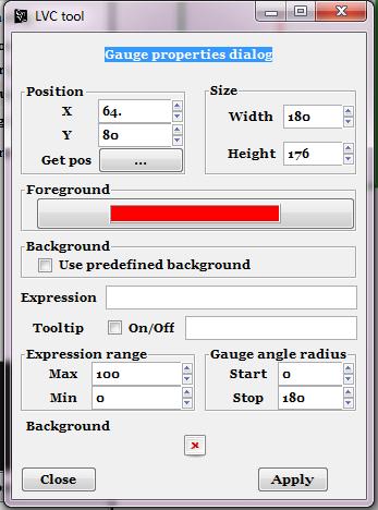
24 Bar graph properties Gauge A dial gauge is used to give a visual representation of an analogue value. A pointer will rotate about the gauge to give a representation of the magnitude of the monitored value. This gauge has no background only pointer, to make background use Background scene. The features of Gauge are: Position on the screen Dimension Color of the value fill Direction and orientation Expression Tooltip label Max value range Min value range Start angle End angle Start angle is the angle of the pointer and vertical axe (12 o clock), when value is equal to Min. Stop angle is the angle of the pointer and vertical axe (12 o clock), when value is equal to Max. The pointer uprising is in clock counter direction. 24

25 Adding Gauge 25
. The symbols are png pictures stored in VT dedicate folders that may be edited by end user.")
26 Gauge properties Digital Widgets Digital widgets are in use to signalize states. Depend of the dedicate expression matrix they appeared predefined symbols. Also they can continuously switching two predefined symbols (blinking). The symbols are png pictures stored in VT dedicate folders that may be edited by end user. One widget may have up to seven expressions, and for each expression that his evaluation is different from 0 (zero) widget can appear one symbol (png picture) or blinking of two symbols (png picture). If the more that one expression is different from 0 the appearance is appropriate to the last one expression. Adding Universal 26

27 Universal properties Adding new symbols to VT is simple. Create new directory in c:\\discovercontrol\vt\resources\images\symbols\ with your custom name and put png pastures that you want, also is possible to just add pictures in already existing folders in this path. After when you open properties in Browse area tree will find new symbols. Command Widgets Command widgets are widget that uses to set value on the plc to the associated variable. 27

28 There are two types simple Command and Set Value. Command is represented as button that sent value 1 to the associated variable on PLC when is pressed. Set Value is widget that show current value of variable on PLC but when is clicked On it appear numerical dialog for setting a integer value to the variable. Command Command widget is essential widget for sending command to the PLC. VT does not guaranty that variable is set after button is pressed. So the user should add some indication (Universal widget) that will confirm action. (See example 1) Adding Command The expression filed should only contain name of the PLC variable. The features of Command are: Position on the screen 28

29 Dimension Color of the Label Label name Expression (PLC variable) Command type (ON/OFF, set 1/0 to PLC variable) Tooltip label Button image (background) Command properties Set value Set value widget is combination of Show value and Command. All time while working it shows current value of assigned plc variable. Left click over it appear dialog with numerical keyboard to type integer value to be set. 29

30 Sounds VT also can alert user by sounds alerts. By clicking on the sound icon on the left side, VT will expand the sound table. Sounds have two dedicate features, expression and sound file. Every two seconds VT evaluates expression and if expression is true it will play sound. Depend of the VT version can be used speech filed. Like common sound when expression is evaluated VT will read expression in speech field evaluate and transform to speech. Only English is available. 30
31 Add background scene To add background image, right click to VT drawing area, select Add background scene. Find your *.png image and check Use background scene. Sounds Device variables VT can communicate with more than one DCPLC device. The all communication getting values end commanding is going over variables. Variables are inter memory space in PLC device. Depend of the PLC type it can be up to 32 variables. All active widgets in VT are reading or writing values to dedicated variables. The table Device variables are interface between VLP project and VT. User can manually adding variable from various PLC device or can automatic import all used variables from VLP project. Variable features are: Unique name Unique address on the PLC device [0,31] Ip address of the parent PLC VT like VLP can work with emulator, and on the Device variables menu is chooser to chose between work with device Ip addresses or with emulator Ip address. Important: Emulator can emulate only one PLC at time, variable name must be unique in table even if there is variables from different address and plc address. 31
32 STANDALONE HMI Device variables The VT standard packet allow to user to create an executive standalone PC HMI application. After the VT project is done and well tested user has option in the Tool tab Create PC HMI. This option create new directory on the Desktop of PC with in exe application of current project. This directory can be copy to another pc and use this HMI application without of installing Discover Control IDE. 32
.")

33 ANDROID HMI Once user starts Android HMI application, it will create necessary folders on user SD card ( Dicover Control folder in root). After this user needs to transfer saved HMI image and its background to proper folders, HMI->HMI, and image->backgrounds. HMI image and background need to have the same name. After that user needs to start Android VT and start his HMI image. First select image, then you will see Current image name, and afterwards you can start HMI. Discover Control Android HMI 33

34 DC PowerStream PLC Discover Control PLC is a device that provides effective automation inside the Discover Control environment. The device possesses 8 digital inputs, 4 digital outputs through relays or 8 direct outputs, 4 analogue inputs and a network card. Power Stream operating system guarantees execution period and processing of the programmed 34
35 circuits. The operating system is based on periodical algorithm, which goes through acquisition, processing of time, processing of the whole diagram of circuits and distribution of signals. Power Supply The power supply for device is in range 8 to 16 [V] DC or AC. There is no direction of wiring because of the grec diodes. Default IP address Power Supply The device has Ethernet communication module only. Only way to communicate with plc is over Ethernet. So the default IP address is The IP address can be changed by VLP Tools -> Set device IP address. Also is set new IP address as the 35
36 device will get dynamic IP address from router. If user set invalid IP address or forget same it can be revert to default ip by factory reset jumper. Digital inputs PLC has 6 digital inputs with independent positive and negative connection points. The current direction is not important. The input voltage in range from 2 to 36 [V] will be seen as logical one. Inputs are protected with optocuplers. Analog inputs Digital inputs PLC has 4 analog inputs in range of 0 to 20 [V]. There is protection from over load. The programming value range is The wire orientation is important. 36
37 Analog inputs Digital outputs PLC has 8 digital outputs, 4 with relays on board. The relays can bi connect to the outputs or disconnect, every of them has dedicated jumper. All digital outputs are connected to pin connector, this is important for connecting with another devices or boards. First four digital outputs are connected to the onboard relays. Relays are with three connections. Read specification on relay box. 37
38 Digital outputs Factory reset The factory reset is using to set revert ip address to default and to delete ladder form device. This is only way to fix device if there is any problem with communication and running ladder. Set jumper on HWReset to position 2-3, and reset device on button and wait until HART Led stop blinking. After return jumper on position 1-2, and rest device again on button. Now the ip is and there is on program on device. The HART Led is on. 38

39 Factory reset 39

40 Appendix A 40
41 I0 Q Q = I0 & I1 I1 I0 Q Q = I0 & I1 & I2 I1 I2 I0 Q Q = I0 I1 I1 I0 Q Q = I0 I1 I2 I1 I2 I0 Q Q =! I0 I0 Q Q =! ( I0 I1) I1 I0 Q Q =! (I0 & I1) I1 I Out1 Out2 Out3 Out4 I = 0 Out1,2,3,4 = 0 I = 1 Out1 =1 Out2,3,4 = 0 I = 2 Out2 =1 Out1,3,4 = 0 I = 3 Out3 =1 Out1,2,4 = 0 I = 4 Out4 =1 Out1,2,3 = 0 I > 4 Out1,2,3,4 = 0 I0 Sum Sum = I0 + I1 I1 I0 Sum Sum = I0 + I1 + I2 I1 I2 I0 Sub Sub = I0 - I1 I1 I0 Mul Mul = I0 * I1 I1 I0 I1 I2 Mul Mul = I0 * I1 * I2 41
42 I0 I1 In (Enable) Mod (counter max Out value) Q Q (count from 0 to Mod - 1) Q = I0 / I1 I > 0 Q[t] = (Q[t - 1] + 1) % Mod In Mod Sel I0 I1 Sel I0 I1 I2 I3 I0 I1 I0 I1 I2 I0 I1 I0 I1 I2 A B I2 A B A B Out Out Out Q = In % Mod Sel = 0 Out = I0 Sel = 1 Out = I1 Sel = 0 Out = I0 Sel = 1 Out = I2 Sel = 2 Out = I3 Sel = 3 Out = I4 Q Q = max (I0, I1) Q Q = max (I0, I1, I2) Min Q = min (I0, I1) Min Q = min (I0, I1, I2) AgB AlB AeB A > B AgB = 1 AlB,AeB = 0 A < B AlB = 1 AgB,AeB = 0 A = B AeB = 1 AgB,AlB = 0 AlB A < B AlB = 1 A > = B AlB = 0 AeB A = B AeB = 1 A < > B AeB = 0 42
43 R Q S I Q It-1 = 0, It = 1 Qt = 1 Qt+ 1 = 0 Qt-1 = 0 I Q It-1 = 1, It = 0 Qt = 1 Qt+ 1 = 0 Qt-1 = 0 I Out Out = I(t 1) VAL VAR On Off IN PT IN PT IN PT VAR OnOff Q ET Q ET Q ET T = t0 VAR = VAL (init) T = t0 + n VAR = VAR () T0, On = 1 & Off = 0, T > T0 OnO = 1 T0, Off = 1 T > T0 OnO = 0 Timer ON delay See diagrams below Timer OFF Delay See diagrams below Pulse generator See diagrams below 43
44 TP Timing diagram TON Timing diagram TOF Timing diagram 44
U90 Ladder Software Manual. Version 3.50, 6/03
 U90 Ladder Software Manual Version 3.50, 6/03 Table Of Contents Welcome to U90 Ladder... 1 Program Editors... 1 Project Navigation Tree...1 Browse Sequences...1 Printing Documentation...2 Interface Language...
Getting Started With the CCPilot VI and QuiC
 Page 1 of 24 Getting Started With the CCPilot VI and QuiC Page 2 of 24 Table of Contents Purpose... 3 What You Will Need... 4 Install the QuiC Tool... 6 Install the QuiC Runtime... 7 Basics of the QuiC
IGSS Configuration Workshop - Exercises
 IGSS Configuration Workshop - Contents Exercise 1: Working as an Operator in IGSS... 2 Exercise 2: Creating a New IGSS Project... 18 Exercise 3: Create Areas and Diagrams in Definition... 23 Exercise 4:
VisionTouch 5 Software
 User Manual VisionTouch 5 Software Greengate Contents Contents Description General Information.... 3 Hardware and Software Requirements.... 3 Hardware Requirements.... 3 Software Requirements... 3 VisionTouch
Getting started with JMobile Suite
 Getting started with JMobile Suite This documents includes a brief presentation of the JMobile HMI and explains in few steps how to get started with it Sitek S.p.A. Tn294 Ver. 1.00 Copyright 2008 Sitek
Tutorial 3: Using the Waveform Viewer Introduces the basics of using the waveform viewer. Read Tutorial SIMPLIS Tutorials SIMPLIS provide a range of t
 Tutorials Introductory Tutorials These tutorials are designed to give new users a basic understanding of how to use SIMetrix and SIMetrix/SIMPLIS. Tutorial 1: Getting Started Guides you through getting
Setup Examples. NetArrays Project Program Development
 Setup Examples NetArrays Project Program Development NetArrays Project Program Development Example 2005, 2007, 2008, 2009 RTP Corporation Not for reproduction in any printed or electronic media without
Introduction to Electronics Workbench
 Introduction to Electronics Workbench Electronics Workbench (EWB) is a design tool that provides you with all the components and instruments to create board-level designs on your PC. The user interface
IGSS 13 Configuration Workshop - Exercises
 IGSS 13 Configuration Workshop - Exercises Contents IGSS 13 Configuration Workshop - Exercises... 1 Exercise 1: Working as an Operator in IGSS... 2 Exercise 2: Creating a new IGSS Project... 28 Exercise
IEC PROGRAMMING
 IEC 61131-3 PROGRAMMING 5 Trio Motion Technology 5-2 Software Reference Manual Introduction to IEC 61131-3 This help file covers program using IEC 61131 languages using Trio Motion Technology s Motion
Quick Start Guide. SR Logic Controller SuperCAD. Introduction. Features. Accessories
 Introduction The SR family of programmable logic controllers provide a compact control unit offering a range of expansion options. The product family is supported with, a PC (Windows) based software development
RIVA / Athena Pro-Series ECU
 RIVA / Athena Pro-Series ECU USING SOFTWARE (MAYA) Running Maya for First Time Once installed, Maya is available in the Start menu under Programs -> Maya, or from a desktop short cut, if created. The first
Courseware Sample F0
 Electric Power / Controls Courseware Sample 3617-F ELECTRIC POWER / CONTROLS COURSEWARE SAMPLE by the Staff of Lab-Volt (Quebec) Ltd Copyright 24 Lab-Volt Ltd All rights reserved. No part of this publication
Exhibitor Software User s Manual. Exhibitor Software V
 Exhibitor Software User s Manual Exhibitor Software V1.0.1 090908 1 Contents 1. Exhibitor Software 2. Installation 3. Using Exhibitor Program 3.1 Starting the Program 3.2 Logging in to the Program 3.3
Ch 9 Discrete Control Using PLCs and PCs
 Ch 9 Discrete Control Using PLCs and PCs Sections: 1. Discrete Process Control 2. Ladder Logic Diagrams 3. Programmable Logic Controllers 4. Personal Computers Using Soft Logic Discrete Process Control
Distributors News. December, 2004 Unitronics has announced a major market release. The release includes:
 MAJOR RELEASE VISILOGIC 4.00, VISION 290, REMOTE ACCESS 4.00 & DATAXPORT 2.00 Unitronics has announced a major market release. The release includes: PID: includes internal Auto-tune Trends: Real-Time HMI
Technical Manual for RT-EX-9017
 Technical Manual for RT-EX-9017 Version 2.01 8 x Analog Input (16 bit) Introduction The EX9017 MODBUS I/O Expansion module is a high-quality and low-cost add-on data acquisition device that allows expanding
Chapter 2 Using Slide Masters, Styles, and Templates
 Impress Guide Chapter 2 Using Slide Masters, Styles, and Templates OpenOffice.org Copyright This document is Copyright 2007 by its contributors as listed in the section titled Authors. You can distribute
Camera control software GigaCam
 Camera control software GigaCam Operation Manual Version 1.06 CONTENTS 1. Starting the software... 3 2. Discovery the Camera... 4 3. Open the Camera... 5 4. Image setting... 6 5. Acquisition start / stop...
1 All of this was put in tables to make it easier to control the layout and format.
 Page 1 of 6 1 All of this was put in tables to make it easier to control the layout and format. Click on StatDisk icon on the Desktop or Click Start, Programs, and StatDisk to Open the StatDisk program.
PediGait IP. Users Manual
 PediGait IP Users Manual April 2012 Table of Contents Clients Tab... 2 Open a Client file... 2 Delete Client file(s)... 2 Edit a Client... 3 Add a new client... 3 Add Comments to client files... 4 Profiles
ATL20 ATL30 Automatic transfer switch controller
 I 194 GB 07 07 ATL20 ATL30 Automatic transfer switch controller REMOTE CONTROL SOFTWARE MANUAL Summary Introduction... 2 Minimum resources of the PC... 2 Installation... 2 Activation of the PC-ATL connection...
HART / EtherNet/IP Gateway GT200-HT-EI User Manual V 1.0 REV A SST Automation
 HART / EtherNet/IP Gateway GT200-HT-EI V 1.0 REV A SST Automation E-mail: SUPPORT@SSTCOMM.COM WWW.SSTCOMM.COM Catalog 1 Product Overview... 4 1.1 Product Function...4 1.2 Product Features... 4 1.3 Technical
AX3000 Platine Terminal Ethernet TCP/IP
 AX3000 Platine Terminal Ethernet TCP/IP Model 60 Installation Guide September 00 - Ref: I60IE010-1 Model AX3000/M60 The reproduction of this material, in part or whole, is strictly prohibited. For additional
ICP DAS WISE User Manual for WISE-71xx Series. [Version 1.03]
![ICP DAS WISE User Manual for WISE-71xx Series. [Version 1.03]](/thumbs/77/75426268.jpg "ICP DAS WISE User Manual for WISE-71xx Series. [Version 1.03]") ICP DAS WISE User Manual for WISE-71xx Series [Version 1.03] Warning ICP DAS Inc., LTD. assumes no liability for damages consequent to the use of this product. ICP DAS Inc., LTD. reserves the right to
ICP DAS WISE User Manual for WISE-71xx Series [Version 1.03] Warning ICP DAS Inc., LTD. assumes no liability for damages consequent to the use of this product. ICP DAS Inc., LTD. reserves the right to
nettalk DUO WiFi Configuration (using an Android smartphone)
") nettalk DUO WiFi Configuration (using an Android smartphone) Step 1. Activate your Device a. Locate your username and password inside of the box. b. Go to www.nettalk.com/activate and follow the activation
nettalk DUO WiFi Configuration (using an Android smartphone) Step 1. Activate your Device a. Locate your username and password inside of the box. b. Go to www.nettalk.com/activate and follow the activation
Machine Controller MP900/MP2000 Series New Ladder Editor USER'S MANUAL
 YASKAWA Machine Controller MP900/MP2000 Series New Ladder Editor USER'S MANUAL YASKAWA MANUAL NO. SIEZ-C887-13.2B Copyright 2001 YASKAWA ELECTRIC CORPORATION All rights reserved. No part of this publication
PLC control system and HMI in the Pharmaceutical World
 PLC control system and HMI in the Pharmaceutical World A typical PLC control system consists of the hardware, software and network components, together with the controlled functions and associated documentation.
EMT1250 LABORATORY EXPERIMENT. EXPERIMENT # 6: Quartus II Tutorial and Practice. Name: Date:
 EXPERIMENT # 6: Quartus II Tutorial and Practice Name: Date: Equipment/Parts Needed: Quartus II R Web Edition V9.1 SP2 software by Altera Corporation USB drive to save your files Objective: Learn how to
Thyro-PX Software and Touch Display
 User Guide 57010174-00A August 2017 Related Documentation For complete information on the Thyro-PX unit, see the user manual that accompanied the system. In particular, reference the safety information
Weidmüller Configurator (WMC) User manual
 User manual") Weidmüller Configurator (WMC) User manual Version 2018-11 Software version: V6.118.0.6999 1 Inhalt Introduction... 4 Installation guide... 4 How to... 4 System requirements... 4 First steps... 4 New project...
Weidmüller Configurator (WMC) User manual Version 2018-11 Software version: V6.118.0.6999 1 Inhalt Introduction... 4 Installation guide... 4 How to... 4 System requirements... 4 First steps... 4 New project...
LABEL MATRIX TEKLYNX V E R S I O N 8 Q U I C K S T A R T G U I D E
 TEKLYNX LABEL MATRIX V E R S I O N 8 Q U I C K S T A R T G U I D E Note Quick Start Guide The information in this manual is not binding and may be modified without prior notice. Supply of the software
NOVUS AUTOMATION 1/92
 INSTRUCTION MANUAL V1.1x INTRODUCTION... 3 CONNECTIONS AND INSTALLATION... 4 MECHANICAL INSTALLATION... 4 ATTACHING AND DETACHING THE FRONT COVER... 8 ATTACHING AND DETACHING THE HMI... 9 ELECTRICAL CONNECTIONS...
Micro800 Controllers Starter Pack Quick Start
 Quick Start Micro800 Controllers Starter Pack Quick Start Catalog Numbers Bulletin 2080-LC20, 2080-LC30, 2080-LC50 Important User Information Read this document and the documents listed in the additional
Avaya C360 SMON User Guide
 Avaya C360 SMON User Guide May 2004 Avaya C360 SMON User Guide Copyright 2004 Avaya Inc. All Rights Reserved The products, specifications, and other technical information regarding the products contained
OpenForms360 Validation User Guide Notable Solutions Inc.
 OpenForms360 Validation User Guide 2011 Notable Solutions Inc. 1 T A B L E O F C O N T EN T S Introduction...5 What is OpenForms360 Validation?... 5 Using OpenForms360 Validation... 5 Features at a glance...
Lab 4 - Data Acquisition
 Lab 4 - Data Acquisition 1/13 Lab 4 - Data Acquisition Report A short report is due at 8:00 AM on the Thursday of the next week of classes after you complete this lab. This short report does NOT need to
MULTIPROG QUICK START GUIDE
 MULTIPROG QUICK START GUIDE Manual issue date: April 2002 Windows is a trademark of Microsoft Corporation. Copyright 2002 by KW-Software GmbH All rights reserved. KW-Software GmbH Lagesche Straße 32 32657
SIMATIC TI505. SINEC H1 Communication Processor. User Manual. Order Number: PPX: Manual Assembly Number: Second Edition
 SIMATIC TI505 SINEC H1 Communication Processor User Manual Order Number: PPX:505 8126 2 Manual Assembly Number: 2586546 0087 Second Edition Copyright 1994 by Siemens Industrial Automation, Inc. All Rights
PduSetup User Manual. Professional Electronics for Automotive and Motorsport
 Professional Electronics for Automotive and Motorsport 6 Repton Close Basildon Essex SS13 1LE United Kingdom +44 (0) 1268 904124 info@liferacing.com www.liferacing.com PduSetup User Manual Document revision:
Get Started. Estimating Explorer
 Get Started Estimating Explorer NOTICE This document and the Sage Timberline Office software may be used only in accordance with the accompanying Sage Timberline Office End User License Agreement. You
IMO. ismart. Training Manual
 IMO ismart Training Manual automation@imopc.com IMO IMO Precision Controls 1000 North Circular Rd Staples Corner London NW2 7JP Tel: +44 (0) 208 452 6444 Fax: +44 (0) 208 450 2274 Email: sales@imopc.com
1 General Information
 2013 PLC 1 General Information Controller configuration: main block Visio V230-13-B20 standard version addit. module Snap-in I/0 V200-18-E1B or V200-18-E2B Program uses operands with fixed addresses: I
Quick Start. Chapter. In This Chapter:
 Chapter Quick Start In This Chapter: Getting to Know Windows.... - Installation of irectsoft 6.... - Getting Started.... -8 Welcome to irectsoft00.... - Begin Editing a Program.... -4 Establish the Communication
Micro800 and Connected Components Workbench. Getting Started Guide. Copyright 2011 Rockwell Automation, Inc.
 Micro800 and Connected Components Workbench Getting Started Guide Copyright 2011 Rockwell Automation, Inc. Table of Contents Chapter 1: Software Requirements and Installing the Software Chapter 2: Create
TouchKit Touch Panel User manual for WindowsNT4 Version: 3.1.4
 TouchKit Touch Panel User manual for WindowsNT4 Version: 3.1.4 TouchKit Touch Panel v3.1.4 0 CONTENT CHAPTER 1. TOUCH PANEL CONTROLLER...2 1.1 CONTROLLER...2 1.2 SPECIFICATIONS AND FEATURES...3 CHAPTER
An OR Operation. Or (O) Function I0.4 Q0.1 I0.5 I0.5 I0.4 Q0.1. Input 3. Input 4. Output 2
 Function I0.4 Q0.1 I0.5 I0.5 I0.4 Q0.1. Input 3. Input 4. Output 2") An OR Operation In this example an OR operation is used in network. It can be seen that if either input I0.2 (input 3) or (O in the statement list) input I0.3 (input 4), or both are true, then output Q0.
An OR Operation In this example an OR operation is used in network. It can be seen that if either input I0.2 (input 3) or (O in the statement list) input I0.3 (input 4), or both are true, then output Q0.
TouchKit TouchScreen Controller User Manual for Windows NT4 Version: 3.4.0
 TouchKit TouchScreen Controller User Manual for Windows NT4 Version: 3.4.0 1 CONTENT CHAPTER 1. TOUCH PANEL CONTROLLER 2 1.1 Controller 2 1.2 Specifications and Features 3 CHAPTER 2. INSTALLING TOUCHKIT
Creating electrical designs
 Creating electrical designs 27.09.2018-34 TABLE OF CONTENTS Table of contents... 2 Introduction... 4 What you learn with this content... 5 Starting G-Electrical... 6 Interface... 6 Drawing area (1)...
To program and test PLC ladder programs that use timer instructions. Timer Instructions of the Trainer PLC. the timer-on-delay (TON) instruction;
 instruction;") Exercise 5 Timer Instructions EXERCISE OBJECTIVE To program and test PLC ladder programs that use timer instructions. DISCUSSION Introduction PLC timer instructions are output instructions that can be
Exercise 5 Timer Instructions EXERCISE OBJECTIVE To program and test PLC ladder programs that use timer instructions. DISCUSSION Introduction PLC timer instructions are output instructions that can be
TouchKit Touch Panel User manual for WindowsNT4 Version: 3.1.4
 TouchKit Touch Panel User manual for WindowsNT4 Version: 3.1.4 TouchKit Touch Panel v3.1.4 0 CONTENT CHAPTER 1. TOUCH PANEL CONTROLLER... 2 1.1 CONTROLLER... 2 1.2 SPECIFICATIONS AND FEATURES... 3 CHAPTER
QUICK START GUIDE Paralleling and Protection Unit PPU 300
 QUICK START GUIDE Paralleling and Protection Unit PPU 300 DEIF A/S Frisenborgvej 33 DK-7800 Skive Tel.: +45 9614 9614 Fax: +45 9614 9615 info@deif.com www.deif.com Document no.: 4189341107C 1. Introduction
Student Quick Reference Guide
 Student Quick Reference Guide How to use this guide The Chart Student Quick Reference Guide is a resource for PowerLab systems in the classroom laboratory. The topics in this guide are arranged to help
Transforming Objects in Inkscape Transform Menu. Move
 Transforming Objects in Inkscape Transform Menu Many of the tools for transforming objects are located in the Transform menu. (You can open the menu in Object > Transform, or by clicking SHIFT+CTRL+M.)
Table of Contents. Part I USB Communication. Part II User Interface. Part III User Settings (Tab Control) DFS-1000 Dataview. 2 File Menu.
 DFS-1000 Dataview. 2 File Menu.") 2 Table of Contents Part I USB Communication 3 1 Important... Information 3 2 Connecting... Controller 3 Part II User Interface 4 1 Overview... 4 2 File Menu... 5 3 Options... Menu 6 4 Help Menu... 6 5
2 Table of Contents Part I USB Communication 3 1 Important... Information 3 2 Connecting... Controller 3 Part II User Interface 4 1 Overview... 4 2 File Menu... 5 3 Options... Menu 6 4 Help Menu... 6 5
Phone: Fax: Web: -
 Table of Contents How to Use GTWIN 1. Functions of Parts...1-1 1.1 Screen Names of GTWIN... 1-2 1.2 Menu Bar... 1-3 1.3 Toolbar... 1-4 1.4 Screen Manager... 1-6 1.5 Parts Library... 1-7 1.6 Graphicbar...
General Information 1. Connection 2. User Interface 3 ATC5300. Menus 4. Automatic Transfer Controller. Remote Control Software Manual A5E
 s General Information 1 Connection 2 Automatic Transfer Controller User Interface 3 Menus 4 Remote Control Software Manual Edition 01/2010 A5E02469028-01 Legal information Warning notice system This manual
TouchKit TouchScreen Controller User Guide for Windows NT4 Version: 3.2.1
 TouchKit TouchScreen Controller User Guide for Windows NT4 Version: 3.2.1 TouchKit Guide for WinNT4 v3.2.1 0 CONTENT CHAPTER 1. TOUCH PANEL CONTROLLER... 2 1.1 CONTROLLER... 2 1.2 SPECIFICATIONS AND FEATURES...
Freeduino USB 1.0. Arduino Compatible Development Board Starter Guide. 1. Overview
 Freeduino USB 1.0 Arduino Compatible Development Board Starter Guide 1. Overview 1 Arduino is an open source embedded development platform consisting of a simple development board based on Atmel s AVR
Avaya C460 SMON User Guide
 Avaya C460 SMON User Guide August 2003 Avaya C460 SMON 5.2 User Guide Copyright 2003 Avaya Inc. All Rights Reserved The products, specifications, and other technical information regarding the products
LCD MODULE INSTRUCTIONS
 LCD MODULE INSTRUCTIONS Overview: The LCD Module is an optional module that allows live data to be displayed right in your vehicles dash. It is completely customizable and shows 10 separate channels of
CALUMMA Management Tool User Manual
 CALUMMA Management Tool User Manual CALUMMA Management Tool Your Data Management SIMPLIFIED. by RISC Software GmbH The CALUMMA system is a highly adaptable data acquisition and management system, for complex
Automation Interface Requirements for System I/O Interface of a DPC I Welding System
 - 1 - Automation Interface Requirements for System I/O Interface of a DPC I Welding System The DPC I welding system offer several features that are intended to communicate with automation. These features
CHAPTER Wi r i n g NOTICE:
 CHAPTER Wiring NOTICE: Information in this manual may change without notice. Midway Games West Inc. reserves the right to make improvements in equipment function, design, or components as progress in engineering
QUICK START GUIDE. Wireless Pan&Tilt IP Camera FSC880. Smart Reliable Secure. Faleemi Technologies Ltd.
 Wireless Pan&Tilt IP Camera QUICK START GUIDE FSC880 Smart Reliable Secure Faleemi Technologies Ltd www.faleemi.com support@faleemi.com support@faleemi.com www.facebook.com/faleemi Apple, Apple Store,
Table of Contents. The Botron B92700 OMNIGND is a Multi-Ground Continuous Monitoring Automation System.
 Operation Manual Table of Contents Description: The Botron B92700 OMNIGND is a Multi-Ground Continuous Monitoring Automation System. Directory: Overview Pg. 2 Features Pg. 3 Quick Setup Guide Pg. 3 Settings
Grayhill 3Dxx Display Products. Setup and Usage with CoDeSys Development Software
 Grayhill 3Dxx Display Products Setup and Usage with CoDeSys Development Software Revision History Revision Date Description A 09/14/2016 Original Release B 05/02/2017 Added support for Model 3D70 (Seven
5000 Series Audio Matrix
 5000 Series Audio Matrix FOR TECHNICAL SUPPORT CALL 513-795-5332 For more complete system information see the document 5000 Series Audio/Video System Installation & Service Manual 08-316 (11/12/13) Matrix
Where Did My Files Go? How to find your files using Windows 10
 Where Did My Files Go? How to find your files using Windows 10 Have you just upgraded to Windows 10? Are you finding it difficult to find your files? Are you asking yourself Where did My Computer or My
INVERTER A800 PLC Function Quick Start Guide
 INVERTER A800 PLC Function Quick Start Guide FR Configurator2 Compatible For Beginners Sequence Control READ BEFORE USING Before using this product, read this Quick Start Guide and the related manuals
CLSM3 Online Help. Overview of the programming workshop. Overview of the programming workshop. Overview of the Programming Workshop.
 Page 1 sur 249 CLSM3 Online Help Online Help version 5.4 29/03/2006 Overview of the programming workshop At a Glance Subject of this Section This section provides an overview of the programming workshop
Familiarization with the PLC Trainer and RSLogix 500
 Exercise 1 Familiarization with the PLC Trainer and RSLogix 500 EXERCISE OBJECTIVES To become familiar with the Lab-Volt PLC Trainer To run the RSLogix 500 software. To enter the default project files
CENTAUR S REAL-TIME GRAPHIC INTERFACE V4.0 OPERATOR S MANUAL
 CENTAUR S REAL-TIME GRAPHIC INTERFACE V4.0 OPERATOR S MANUAL TABLE OF CONTENTS Installation... 6 Introduction to Centaur s real-time Graphic Interface... 6 Computer Requirements... 7 Operating System
Axon HD Content Management Application (CMA)
") [ ] Axon HD Content Management Application (CMA) A Content Management Application (CMA) running on an Axon HD media server or a computer connected through an Ethernet network gives you remote control of
[ ] Axon HD Content Management Application (CMA) A Content Management Application (CMA) running on an Axon HD media server or a computer connected through an Ethernet network gives you remote control of
Introduction of Configure Software for 3.5'' Touch Panel
 Introduction of Configure Software for 3.5'' Touch Panel 1. Brief Introduction This Configure Software is used with the 3.5'' Touch Panel. After setting group address of different devices in ETS users
V G23 Rev: 12/04
 Software Manual HMI V230-21-G23 Rev: 12/04 No part of this document may be used for any purpose other than for the purposes specifically indicated herein nor may it be reproduced or transmitted in any
and 32 bit for 32 bit. If you don t pay attention to this, there will be unexpected behavior in the ISE software and thing may not work properly!
 This tutorial will show you how to: Part I: Set up a new project in ISE 14.7 Part II: Implement a function using Schematics Part III: Simulate the schematic circuit using ISim Part IV: Constraint, Synthesize,
Zelio Logic 2 Online Help
 Page 1 of 234 Zelio Logic 2 Online Help Overview of the Zelio Soft 2 Software At a Glance Subject of this Section This section provides an overview of the Zelio Soft 2 software. What's in this Part? This
SOFTWARE FACTORYFLOOR. DATA SHEET page 1/10. Description
 349 DATA SHEET page 1/10 Description Part Number Description FactoryFloor Suite Opto 22 FactoryFloor is a suite of industrial control software applications offering an unprecedented level of price and
Content Management Application (CMA)
") Chapter 13: CHAPTER 13 A running on an Axon HD media server or a computer connected through an Ethernet network gives you remote control of content, software and configuration management functions. The
Chapter 13: CHAPTER 13 A running on an Axon HD media server or a computer connected through an Ethernet network gives you remote control of content, software and configuration management functions. The
JNIOR Series 4 A Network I/O Resource Utilizing the JAVA Platform Getting Started Manual Release 2.0 NOTE: JANOS OS 1.1 or greater required
 JNIOR Series 4 A Network I/O Resource Utilizing the JAVA Platform Getting Started Manual Release 2.0 NOTE: JANOS OS 1.1 or greater required INTEG Process Group, Inc. 2919 East Hardies Rd, First Floor Gibsonia,
L14 - Experience Connected Components Workbench Software to Develop Your Basic Standalone Machine Application
 L14 - Experience Connected Components Workbench Software to Develop Your Basic Standalone Machine Application PUBLIC Copyright 2018 Rockwell Automation, Inc. All Rights Reserved. 1 Connected Components
i³ Display, Control, Connect
 Display, Control, Connect User Guide i 3 User Guide Introduction to i 3 2 Guide to Part Numbers 2 Installing i 3 Configurator Software 3 Powering up and Connecting to an i 3 6 Tour of the i 3 Configurator
To learn how to use Focus in Pix:
 Welcome To learn how to use Focus in Pix: Step-by-step guide Visit www.focusinpix.com/quick-guide for a quick overview of Focus in Pix software. You will also find many tips and tutorials on our site.
How to Get Started. Figure 3
 Tutorial PSpice How to Get Started To start a simulation, begin by going to the Start button on the Windows toolbar, then select Engineering Tools, then OrCAD Demo. From now on the document menu selection
TOSHIBA DesignAIRS. Help & Guide Manual
 TOSHIBA DesignAIRS Help & Guide Manual Contents 1. MAIN TOOLBAR... 3 1.1. Tools / Options... 3 1.1.1. Application Settings... 3 1.1.2. Email Settings... 4 1.1.3. Internet Connection Settings... 4 1.1.4.
Please read this manual carefully before you use the unit and save it for future reference.
 ANDROID STEREO RECEIVER Please read this manual carefully before you use the unit and save it for future reference. Installation Precaution: 1. This unit is designed for using a 12V negative ground system
Bose ControlSpace Designer Software. User Guide
 Bose ControlSpace Designer Software User Guide 2005 Bose Corporation. No part of this work may be reproduced, modified, distributed or otherwise used without prior written permission. Contents Introduction
BEAWebLogic Server. Using the WebLogic Diagnostic Framework Console Extension
 BEAWebLogic Server Using the WebLogic Diagnostic Framework Console Extension Version 10.0 Revised: March 30, 2007 Contents 1. Introduction and Roadmap What Is the WebLogic Diagnostic Framework Console
TABLE OF CONTENTS. i Excel 2016 Basic
 i TABLE OF CONTENTS TABLE OF CONTENTS I PREFACE VII 1 INTRODUCING EXCEL 1 1.1 Starting Excel 1 Starting Excel using the Start button in Windows 1 1.2 Screen components 2 Tooltips 3 Title bar 4 Window buttons
Trio Motion Technology 4-2. Motion Perfect v3
 MOTION PERFECT V3 4 Trio Motion Technology 4-2 Software Reference Manual Introduction to Motion Perfect 3 Motion Perfect 3 is an Microsoft Windows based application for the PC, designed to be used in conjunction
CODESYS V3 Quick Start
 Programming a Garage Door Drive with CODESYS V3 On the following pages we would like to show you how easy it is to program a simple automation project with CODESYS V3. To start with, we would like to make
Introduction to the Visual Studio.NET Integrated Development Environment IDE. CSC 211 Intermediate Programming
 Introduction to the Visual Studio.NET Integrated Development Environment IDE CSC 211 Intermediate Programming Visual Studio.NET Integrated Development Environment (IDE) The Start Page(Fig. 1) Helpful links
Remote Display User Manual
 Remote Display User Manual 1 Contents Features... 3 Hardware Overview... 4 Quickstart Guide... 5 Android Application Operation... 6 Launching and Connecting... 6 Main Display... 7 Configuring Channels...
Content. Page 1 of 29
 Content 1 Installation... 3 1.1 Mervis IDE... 3 1.2 Card... 3 1.2.1 MicroSD card preparation... 3 1.2.2 Deploying image... 3 1.3 Connecting UniPi... 3 1.3.1 Router mode... 4 1.3.2 Direct mode... 4 2 Basic
Quick instructions: Programming of SmartPLC AC14/AC4S with CODESYS V3
 This document is valid for the software bundle: CODESYS V3.5.4.2 AC4S-Package: >= V1.3.2.2 AC4S-Firmware: >= V4.0.2 VNC-rk Page 1 of 28 V1.1 Important note: These instructions are structured so that all
FUN TECH TIPS 101 SUMMER CLOVIS UNIFIED SCHOOL DISTRICT INFORMATION TECHNOLOGY SERVICES Prepared by Tanie McKinzie, TSS III
 FUN TECH TIPS 101 SUMMER 2016 CLOVIS UNIFIED SCHOOL DISTRICT INFORMATION TECHNOLOGY SERVICES Prepared by Tanie McKinzie, TSS III PUBLISHER BASICS... 3 Creating a text box... 3 Adding a picture... 4 Manipulating
GTWIN 1.1 CONTROL TECHNOLOGY CORPORATION. GTWIN 2.8 Quick Start. MGT Panel & GTWIN Quick Start Guide
 GTWIN 1.1 CONTROL TECHNOLOGY CORPORATION GTWIN 2.8 Quick Start MGT Panel & GTWIN Quick Start Guide CONTROL TECHNOLOGY CORPORATION MGT Panel & GTWIN Quick Start Guide Copyright 2004-2007 Control Technology
1-Multitasking with ladder programming on LDmicro4.2 for MEGA 2560 via USB 1-0 The machines to program: 1-1 Settings on LDmicro:
 1-Multitasking with ladder programming on LDmicro4.2 for MEGA 2560 via USB 1-0 The machines to program: 1-1 Settings on LDmicro: 1-2-Program the ladder: a translation of the state diagram I have got some
Help Volume Agilent Technologies. All rights reserved. Agilent E2485A Memory Expansion Interface
 Help Volume 1994-2002 Agilent Technologies. All rights reserved. Agilent E2485A Memory Expansion Interface Agilent E2485A Memory Expansion Interface The E2485A Memory Expansion Interface lets you use the