Options and Accessories For TNC Controls
|
|
|
- Kory Pitts
- 5 years ago
- Views:
Transcription


1 Options and Accessories For TNC Controls 05/2018

2 Options and accessories for TNC controls HEIDENHAIN controls are known for their complete range of features and comprehensive equipment. In addition, they can be optimally adapted to the respective application thanks to a series of control options and accessories. This brochure provides you with a comprehensive overview that is independent of the control version. Options are functions that are integrated in the control and that allow you to tailor the feature range of the TNC to your actual requirements, including at a later time. Some options have to be adapted by the machine tool builder. The options are enabled with a simple keyword. HEIDENHAIN provides you with useful tools for applications outside the TNC in the form of PC software, ranging from software for supporting the transfer of data or for creating a PLC program, all the way to the complete NC programming station. With the hardware enhancements, your work with the machine becomes faster, safer, and simpler. An electronic handwheel, for example, allows especially delicate traverse of the machine, and a workpiece touch probe reduces the time needed for setting up the workpiece. Windows 2000, Windows XP, Windows Vista, Windows 7, Windows 8, and Windows 10 are trademarks of Microsoft Corporation. 2
3 Contents Overview Overview tables 4 Dynamic Precision 10 Dynamic Efficiency 11 Connected Machining 12 Options Programming and operation 13 Machine accuracy 29 Machining functions 36 Communication 45 Interfacing to the machine 47 PC software 53 Hardware enhancements 68 Please also note the page references in the overview tables. 3
4 Overview Option Option number ID TNC 620 TNC 640 Adaptation by OEM Page Programming and operation Machining with a Rotary Table Programming of cylindrical contours as if in two axes Feed rate in mm/min or degrees/min Coordinate Transformation Tilting of the working plane, PLANE function : : X 13 X 14 Display Step down to 0.01 µm or Touch Probe Cycles Compensation of workpiece misalignment, preset setting Automatic tool and workpiece measurement Touch probe input enabled for non-heidenhain systems Extended Programming Functions FK free contour programming Fixed cycles Peck drilling, reaming, boring, counterboring, centering Milling of internal and external threads Clearing of level and oblique surfaces Multi-operation machining of straight and circular slots Multi-operation machining of rectangular and circular pockets Cartesian and polar point patterns Contour train, contour pocket also with contour-parallel machining Special cycles developed by the machine tool builder can be integrated Engraving cycle: engraving of text or numbers in a straight line or on an arc Contour slot with trochoidal milling Program-Verification Graphics, Program-Run Graphics Plan view Projection in three planes 3-D view S S S X S S S S S S 17 Finely Detailed 3-D View S S 18 Pallet Editor S S X 19 DXF Converter importing of contours and machining positions from DXF files CAD Import importing of contours from 3-D models Turning Functions Tool management for turning Tool-tip radius compensation Switching between milling and turning modes of operation Lathe-specific contour elements Package of turning cycles X 23 Eccentric Turning X 24 4 = Available as option = Not available S = Standard
5 Option Option number ID TNC 620 TNC 640 Adaptation by OEM Page Programming and operation Synchronization of two or more spindles Hobbing cycle X 27 Extended Tool Management X 25 Interpolating Spindle interpolation turning X 26 CAD Viewer opening of 3-D CAD data directly on the TNC S S S 28 Batch Process Manager easy-to-understand depiction of the pallet management X 20 Machine accuracy KinematicsOpt touch-probe cycles for automatic measurement of rotary axes KinematicsComp 3-D spatial compensation X 30 CTC (Cross Talk Compensation) compensation of position error through axis coupling PAC (Position Adaptive Control) position-dependent adaptation of control parameters LAC (Load Adaptive Control) load-dependent adaptation of control parameters MAC (Motion Adaptive Control) motion-dependent adaptation of control parameters AVD (Active Vibration Damping) active vibration amplitude reduction X X X X X 35 = Available as option = Not available S = Standard 5
6 Overview Option Option number ID TNC 620 TNC 640 Adaptation by OEM Page Machining functions Interpolation circular, in 3 axes with tilted working plane : Interpolation linear, in 5 axes : Spline Interpolation processing of third-degree polynomials Axis Simultaneous Machining 3-D tool compensation through surface normal vectors Use of the electronic handwheel to change the angle of the swivel head during program run without affecting the position of the tool point (TCPM = Tool Center Point Management) Keeping the tool normal to the contour Tool radius compensation normal to the tool direction Manual traverse in the active tool-axis system : X 36 Handwheel Superimpositioning superimposing of handhweel positioning during program run Tool Compensation radius-compensated contour precalculation (LOOK AHEAD) S S X S S S 38 DCM Dynamic Collision Monitoring X 39 Global Program Settings X 40 AFC Adaptive Feed Control X 41 3D-ToolComp 3-D radius compensation depending on the tool s inclination angle (only with option 9) ACC (Active Chatter Control) active suppression of tool chatter X 43 VSC camera-based monitoring of the setup situation X 44 Communication HEIDENHAIN DNC communication with external Windows applications over COM component Remote Desktop Manager display and remote operation of external computer units (e.g., Windows PC) X X 46 6 = Available as option = Not available S = Standard
7 Option Option number ID TNC 620 TNC 640 Adaptation by OEM Page Interfacing to the machine Additional Control Loops Additional axis X 47 Additional axis X Additional axis X Additional axis X Additional axis X Additional axis X Additional axis X Additional axis X 4 Additional Control Loops X 8 Additional Control Loops X Synchronized Axes gantry axes, tandem tables S S X 48 Python OEM Process realization of special functions X 49 Double Speed short control-loop cycle times for direct drives X 50 OEM Option X 51 RTC Real-Time Coupling function for synchronizing axes and spindles X 52 = Available as option = Not available S = Standard 7
8 Overview PC software TNC 620 TNC 640 Adaptation by OEM Page TNCremo 53 TNCremoPlus 53 TeleService X 54 RemoTools SDK X 45 virtualtnc X 56 PLCdesign X 57 KinematicsDesign X 58 CycleDesign X 59 TNCscope X 60 DriveDiag X 61 TNCopt X 62 IOconfig X 63 Software Key Generator X 64 BMXdesign X 65 FixtureWizard X 66 Programming station Single-user license for demo version 67 Single-user license with TNC keyboard Single-user license with virtual keyboard Network license with virtual keyboard for 1 workstation Network license with virtual keyboard for 14 workstations Network license with virtual keyboard for 20 workstations 8 = Available as option = Not available S = Standard
9 Hardware enhancements ID TNC 620 TNC 640 Adaptation by OEM Page Handwheel HR 130 TTL; panel mounted With detent W/o detent HR µa PP ; panel mounted With detent W/o detent HR 510 portable handwheel With detent W/o detent xx xx HR 510 FS portable handwheel With detent W/o detent xx xx HR 520 portable handwheel with display With detent W/o detent HR 520 FS portable handwheel with display With detent W/o detent HR 550 FS portable wireless handwheel with display With detent W/o detent HRA 551 FS handwheel holder for HR 550 FS Workpiece touch probe TS 260 with cable xx X 69 TS 460 with radio or infrared transmission xx X TS 444 with infrared transmission xx X TS 740 with infrared transmission xx X Tool touch probe TT 160 with cable xx X 70 TT 460 with radio or infrared transmission xx X TL Nano with laser scanning TL Micro 150 with laser scanning TL Micro 200 with laser scanning TL Micro 300 with laser scanning xx xx xx xx X Additional operating station ITC 755 with touchscreen and ASCII keyboard X 71 ITC inch screen; separate TNC keyboard required X ITC inch screen; separate TNC keyboard required ITC inch touchscreen; separate TNC keyboard required X X Industrial PC IPC 6641 for Windows interface on TNC X 72 Camera system VS 101 for workspace monitoring X 73 = Available as option = Not available S = Standard 9

10 Overview Dynamic Precision The term Dynamic Precision encompasses optional functions for HEIDENHAIN controls that are highly effective at reducing the dynamic errors of machine tools. They improve the machine s dynamic performance, attain higher accuracy at the TCP and therefore permit milling at the limit of the technologically possible, regardless of the age of the machine, its load and machining position. And all this is done without any modification of the machine s mechanics. It s no longer necessary to work slowly to achieve accurate parts with high surface definition. With Dynamic Precision, machine tools work with speed and precision. The functions of Dynamic Precision are adapted with high clock rates in the controller unit (a component of HEIDENHAIN controls) to the movements and loads of the machine tool. Because Dynamic Precision consists of software functions, it requires no intervention in the mechanics of the machine or in its power train. However, the machine manufacturer must enable the individual functions, enter their parameters, and adapt them to the machine. High precision together with fast machining is the basis for an increase in productivity. Unit costs are reduced without compromises in accuracy and surface quality. Dynamic Precision also ensures that accuracy is retained regardless of operating time and weight. It isn t necessary to reduce feed rates due to age or load. The functions of Dynamic Precision are available as options for controls from HEIDENHAIN. The machine tool builder can apply them individually as well as in combination. CTC compensation of accelerationdependent position errors at the tool center point, thereby increasing accuracy in acceleration phases AVD Active Vibration Damping for better surfaces PAC position-dependent adaptation of control parameters LAC load-dependent adaptation of control parameters enhances accuracy regardless of load and age MAC motion-dependent adaptation of control parameters TNC 640 TNC 620 Page Dynamic Precision x x x CTC compensation of position errors through mechanical compliance Option Option Option 31 AVD Active Vibration Damping Option Option Option 35 PAC position-dependent adaptation of control parameters LAC load-dependent adaptation of control parameters MAC motion-dependent adaptation of control parameters Option Option Option 32 Option Option Option 33 Option Option Option 34 For more information, see the Dynamic Precision Technical Information and visit 10


11 Dynamic Efficiency With the concept of Dynamic Efficiency, HEIDENHAIN combines innovative TNC functions that help the user to make heavy machining and roughing more efficient while also enhancing process reliability. The software functions support the machine operator but also make the manufacturing process itself faster, more stable and more predictable in short, more efficient. Dynamic Efficiency helps to increase the metal removal rate and reduce machining time. Dynamic Efficiency comprises three software functions: ACC reduces chatter tendencies and permits higher feed rates and greater infeeds AFC controls the feed rate depending on the machining situation Trochoidal milling a function for the roughing of slots and pockets that eases the load on the tool The AFC and ACC functions are later described in detail. They are identified with the Dynamic Efficiency logo. Each solution by itself offers decisive advantages in the machining process. But it is particularly the combination of these TNC features that exploits the potential of the machine and the tool while simultaneously reducing the mechanical load. Changing machining conditions, such as interrupted cuts, various material plunging procedures, and simple clear-out operations are also examples of why these features are worthwhile. In practice, removal rate increases of 20 to 25 percent are possible. Dynamic Efficiency permits higher removal rates and therefore increases productivity without making the user resort to special tools. The avoidance of tool overload and premature tool wear, as well as the additional gain in process reliability, contribute considerably to improved economic efficiency. TNC 640 TNC 620 Page Dynamic Efficiency x x ACC Active Chatter Control Option Option Option 43 AFC Adaptive Feed Control Option Option 41 Trochoidal milling Standard Standard Standard /user For more information, see the Dynamic Efficiency Technical Information and visit 11

12 Connected Machining Solutions for networked manufacturing With its Connected Machining package of functions, HEIDENHAIN offers solutions for the customized networking of production processes. These solutions place the user at the center of digital order management through the control of his milling or turning machine. The HEIDENHAIN control is networked with all of the productionrelated areas of the company on a highly individual basis, with tailoring to already existing structures, and is open for future developments. You benefit from workload reduction thanks to simple data usage, time-saving workflows, and transparent processes in all areas of your company not only in the shop but also in the areas of design and production planning, as well as in management, logistics, and servicing, etc. The manufacturing strengths of modern machines and plants are thus supplemented by the uniformly digital job management of Connected Machining. Even a simple TNC control system integrated into the company network via Ethernet offers, with its standard functions, a wide range of possibilities for receiving and using digital job data directly on the control: PDF viewer (e.g., for displaying fixture diagrams and design drawings) CAD Viewer (e.g., for displaying 3-D models) Image display (e.g., for displaying fixture setups and production notes) Web browser for accessing web-based applications, such as ERP and MES clients, clients, and HTML5 clients Beyond this, the following solutions and options are offered: The StateMonitor software makes processes transparent through data acquisition and data analysis The Remote Desktop Manager (option 133) allows access to PCs and the software installed on them, right at the control The HEIDENHAIN DNC interface (option 18) links the control to ERP and production-activity control systems The Extended Workspace display provides clear representation and processing of the job data on the machine TNC 640 TNC 620 Page Connected Machining x x x StateMonitor x 55 Remote Desktop Manager Option Option Option 46 HEIDENHAIN DNC Option Option Option 45 Extended Workspace x 71 For more information, see the Connected Machining brochure 12

13 Programming and operation Machining with a Rotary Table Many 5-axis operations that, at first glance, may seem very complex can be reduced to conventional 2-D movements that are merely wrapped around a cylindrical surface. The TNC supports you with application-oriented functions to help you write and edit such programs quickly and simply without a CAM system. Cylinder surface machining With the TNC, it is easy to program contours (consisting of straight lines and arcs) on cylindrical surfaces using rotary and tilting tables: you simply program the contour in a plane as if the cylinder surface were unrolled (regardless of the axis on the TNC 640, TNC 620, and ). The TNC then calculates and machines the corresponding cylindrical contour. The TNC features four cycles for cylindrical surface machining: Slot milling (the slot width is the same as the tool diameter) Guide-groove milling (the slot width is greater than the tool diameter) Ridge milling Outside contour milling Feed rate for rotary axes and tables in mm/min In the standard version, the feed rate of rotary axes is programmed in degrees/min. However, the TNC can also interpret this feed rate in mm/min. The feed rate at the contour is then independent of the distance of the tool center from the center of the rotary axis. Machining with a Rotary Table // HSCI/ Option 8 ID ID HSCI As of NC SW 34059x-01 As of NC SW 34056x-01/73498x-01/81760x-01 As of NC SW 34055x-01/ As of NC SW 60642x-01 As of NC SW 34049x-01 For more information, see the TNC brochures and visit 13


14 Programming and operation Coordinate Transformation tilting of the working plane, PLANE function Programs for contours and holes on inclined surfaces are often very complex and require time-consuming computing and programming work. Here the TNC helps you to save a great deal of programming time. You program the machining operation as usual in the main plane for example, in X/Y. The machine then runs the program in a plane that has been tilted by one or more rotary axes with respect to the main plane. The PLANE feature makes it easy to define a tilted working plane; you can specify tilted working planes in seven different ways, depending on the information in the workpiece drawing. In order to keep the use of these complex functions as simple as possible, a separate animation is available for each possible plane definition, so that you can view them before selecting the function. Clearly arranged support graphics assist you during input. You can also use the PLANE function to define the positioning behavior for tilting so that there are no unpleasant surprises when the program is run. The settings for defining the positioning behavior are identical for all PLANE functions, making everything that much easier. Coordinate Transformation // HSCI/ Option 8 ID ID HSCI As of NC SW 34059x-01 As of NC SW 34056x-01/73498x-01/81760x-01 As of NC SW 34055x-01/ As of NC SW 60642x-01 As of NC SW 34049x-01 For more information, see the TNC brochures and visit 14
15 Programming and operation Touch Probe Cycles Workpiece alignment With HEIDENHAIN touch probes and the probing functions of the TNC, you can forgo any tedious manual alignment of the workpiece: Clamp the workpiece in any position The touch probe ascertains the workpiece misalignment by probing a surface, two holes, or two studs The TNC compensates for the misalignment with a basic rotation, meaning that the machining program is rotated by the amount of the measured misalignment Compensating for workpiece misalignment by rotating the coordinate system or turning the table Preset setting Fast and reliable definition of the preset reduces nonproductive time and increases machining accuracy. The TNC features a large number of probing cycles for the automatic setting of presets. Workpiece inspection The TNC features a number of measuring cycles for checking the geometry of the machined workpieces. This enables you to do the following: Recognize a workpiece and call an appropriate part program Check whether all machining operations were conducted correctly Detect and compensate for tool wear, etc. Tool measurement Together with the TT or TL touch probes for tool measurement, the TNC makes it possible to measure tools automatically while they are in the machine spindle. The TNC saves the ascertained values for tool length and radius in the central tool file. By inspecting the tool during machining, you can quickly and directly measure wear or breakage to prevent scrap or rework. Setting a preset at a corner, for example, or in the center of a circular hole pattern Workpiece measurement (e.g., the angle of a plane or rectangular pocket) Tool measurement (e.g., tool length and radius or tool wear) Touch Probe Cycles Option 17 ID HSCI/ Standard As of NC SW 34056x-01/73498x-01/81760x-01 Standard Standard For more information, see the TNC brochures and the Touch Probes brochure 15

16 Programming and operation Advanced Programming Functions FK free contour programming, fixed cycles FK free contour programming Not all workpieces are dimensioned for conventional NC programming. Thanks to FK, the control s free contour programming feature, in such cases you simply type in the data from the drawing without first having to convert or calculate your data! It does not matter if individual contour elements are not completely defined as long as the complete contour has been. If the given data result in more than one mathematical solution, then the helpful TNC programming graphics will offer the possible variants for selection. Standard cycles Besides the fixed cycles for drilling and tapping (with or without floating tap holder), with option 19 there are cycles for thread milling, reaming, boring, and for hole patterns, as well as milling cycles for clearing plane surfaces and for roughing and finishing pockets, slots, and studs. Cycles for complex contours The Subcontour List (SL) cycles are particularly helpful for clearing pockets with combined contours. This term is used to identify machining cycles for pilot drilling, roughing, and finishing when the contour or subcontours are specified in subprograms. In this way, one contour description can be used for more than one operation using different tools. OEM cycles As original equipment manufacturers, machine tool builders can contribute their special manufacturing know-how by designing additional fixed cycles and saving them in the TNC. However, the end user can write his own cycles as well. HEIDENHAIN makes this possible with its PC program CycleDesign. CycleDesign enables you to organize the input parameters and soft-key structure of the TNC to suit your own needs. Advanced Programming Functions Option 19 ID HSCI Standard As of NC SW 34056x-01/73498x-01/81760x-01 Standard Standard Standard Installation by the user For more information, see the TNC brochures and visit 16

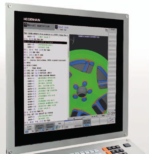
 In 3-D view Details can be displayed with")
17 Programming and operation Program-Verification Graphics, Program-Run Graphics Programming graphics HEIDENHAIN controls support you with detailed programming graphics. The programming graphics function is available as a standard feature on all controls and is described in the respective product brochures. Various other graphic views are optional: Test graphics To be on the safe side before running a program, the TNC can graphically simulate the machining of the workpiece. The TNC can display the simulation in the following ways: In plan view with different levels of depth In three projections (as in the workpiece drawing) In 3-D view Details can be displayed with magnification. In addition, the TNC indicates the calculated machining time in hours, minutes and seconds. Program-run graphics The TNC shows a real-time graphic of the machining progress. Coolant spray and protective enclosures usually obstruct any direct view of the actual workpiece. You can get around this with a simple keystroke to see the simulated progress of workpiece machining. Program-Verification Graphics, Program-Run Graphics HSCI Option 20 ID Standard As of NC SW 34056x-01/73498x-01/81760x-01 Standard Standard Standard Installation by the user For more information, see the TNC brochures and visit 17

18 Programming and operation Detailed 3-D view in the program-verification and program-run graphics Finely detailed 3-D view The program-verification and the programrun graphics of the TNC 640, TNC 620 and include further view options with detailed 3-D view. They help you to evaluate the workpiece quality in the simulation even before the actual machining operation begins, as well as during real-time machining. The high-resolution 3-D view with high zoom factors reveals the tiniest program errors on the workpiece surface. It also provides the possibility of showing the tool paths, including the associated block numbers, in order to permit an even closer analysis of the NC data. The selectable workpiece transparency feature that makes it possible to detect hidden cavities and undercuts is also very useful. The enhanced graphics also improve the visibility of tool-specific machining operations: all machining operations that are performed with one and the same tool are depicted in their own color. The TNC also features a measuring function in the 3-D view. You can position the mouse pointer anywhere in the graphic to see the coordinates. If you just need a quick overview of the contour and the machining time, you can change the resolution and the simulation mode to allow for an accelerated calculation. Program-Verification Graphics, Program-Run Graphics HSCI Option 20 ID Standard as of NC SW 34059x-04 As of NC SW 81760x-01 Standard as of NC SW For more information, see the TNC brochures and visit 18

19 Programming and operation Pallet Editor The TNC can assign the appropriate program and corresponding datum shift to parts that are mounted on pallets and brought to the machine in a random sequence. If a pallet is inserted for machining, the TNC automatically calls the correct program. This permits automatic machining of a variety of parts in any sequence. Pallet movement can be controlled via PLC axes. The order of movement, as well as the pallet and workpiece presets, must be defined in the pallet table by the user. The pallet table is freely configurable by the machine tool builder, which means that any information can be stored in the tables and called up later by the PLC. The execution of pallet tables can be workpiece-oriented or tool-oriented (with the, TNC 640 as of NC SW 34059x-08, and with the TNC 620 as of NC SW 81760x-05). Pallet Editor Option 22 ID HSCI Standard As of NC SW 34056x-01/73498x-01/81760x-01 Standard Standard For more information, see the TNC brochures 19

20 Programming and operation Batch Process Manager easy-to-understand depiction of the pallet management The Batch Process Manager is a powerful function for pallet machining and series production. With the clear-cut user interface, you plan your production process and receive important information about the upcoming operations. The Batch Process Manager automatically checks for missing tools, insufficient tool life, and required manual tool changes. The result of the check is displayed in the status overview. In the Batch Process Manager, the following information is already displayed in advance: Sequence of operations Time of next manual intervention (option 93 required) Program duration and run time (option 93 required) Status information (option 93 required): preset, tool and program Batch Process Manager Option 154 Option 93 ID ID HSCI As of NC SW 34059x-08 As of NC SW 81760x-01 For more information, see the TNC 620 and TNC 640 brochures 20


21 Programming and operation DXF Converter importing of contours and machining positions from DXF files Why program contours when your drawing is already in DXF format anyway? You can open DXF files directly on the TNC in order to extract contours or machining positions from it. This not only saves time otherwise spent on programming and testing but also provides assurance that the finished contour is exactly in accordance with the design engineer s specifications. As a rule, DXF files contain multiple layers with which the design engineer organizes a drawing. In order to have as little unnecessary information as possible on the screen, you can hide all of the excess layers contained in the DXF file at a keystroke. This requires an operating panel with touchpad or an external pointing device. The TNC can select a contour train even if it has been saved across different layers. The TNC also provides support when you define the workpiece preset. The TNC has a function for this, with which you can shift the datum in the drawing to a suitable location, simply by clicking on an element. Contour selection is exceptionally user friendly. You select any element by clicking it with the mouse. As soon as you select a second element, the TNC detects your desired direction of machining and starts the automatic contour detection feature. The TNC automatically selects all clearly identifiable contour elements until the contour closes or branches out. There you click the immediately following contour element. In this way, you can define even complex contours with just a few mouse clicks. If desired, you can also shorten, lengthen or interrupt the contour elements. You can also easily select machining positions and save them as point files, particularly in order to transfer drilling positions or starting points for pocket machining. Naturally, the TNC saves the machining positions such that they can be reached by the shortest path. With the CAD Import option, you can also import contours and machining positions from 3-D models (see CAD Import, p. 22). DXF Converter Option 42 ID HSCI As of NC SW 34059x-02 As of NC SW 73498x-02/81760x-01 As of NC SW As of NC SW 60642x-01 As of NC SW 34049x-02 Installation by the user For more information, see the TNC brochures and visit 21

22 Programming and operation CAD Import importing of contours from 3-D models CAD Import (option) The CAD Viewer enables the display of 2-D and 3-D models (e.g., in DXF, STEP, or IGES file formats) right on the TNC. Using the CAD Import option, you can easily and directly incorporate contours and machining positions from these CAD files into your Klartext program. You can thereby reduce the amount of programming work and avoid input errors resulting from transposed digits or incorrectly placed decimal points, for example. Extracting machining information directly from CAD data particularly provides additional possibilities for creating NC programs with a tilted machining plane. You can define the preset with a 3-D basic rotation on the 3-D model. Plus, you can place a datum with the appropriate 3-D rotation on the desired working plane. You can conveniently save the working plane in the clipboard and transfer it to the NC program with the appropriate transformation and associated PLANE command. On the defined working plane, you can extract contours and machining positions and apply them to the NC program. Selecting the contour is particularly convenient. You select any element by clicking it with the mouse. As soon as you select a second element, the TNC detects your desired direction of machining and starts automatic contour detection. The TNC automatically selects all clearly identifiable contour elements until the contour closes or branches out. By this means, you can define extensive contours with just a few mouse clicks. Then you can simply copy the selected contour to an existing Klartext program via the clipboard. The CAD Import option is an expansion of the DXF Converter. All previous functions have been adopted and expanded to include 3-D import functions. In addition, nearly all of the common DXF, STEP, and IGES file formats can be used. The CAD Import option is available for the TNC 640, TNC 620, and controls. CAD Import Option 42 ID HSCI As of NC SW 34059x-08 As of NC SW 81760x-08 As of NC SW Installation by the user For more information, see the brochures and visit 22


23 Programming and operation Turning Functions milling and turning on the same machine with the TNC 640 The TNC 640 offers you powerful functions that enable you to switch between turning mode and milling mode as desired in the NC program under program control. This enables you to decide with complete freedom how and when you want to combine the two machining methods. Programming as accustomed You can program turning operations as always with convenient dialog guidance in HEIDENHAIN Klartext. Besides the standard path functions, you can also use FK free contour programming to easily create contour elements not otherwise dimensioned for NC. In addition, turningspecific recessing and undercutting contour elements are available and can be defined with the help of informative help illustrations. Cycles for milling and turning HEIDENHAIN controls have always been known for their comprehensive and technologically sophisticated package of cycles. Frequently recurring operations that comprise several steps are also stored in the TNC 640 as cycles. You program them under conversational guidance and are supported by enlightening help graphics that clearly illustrate the required input parameters. Besides the well-known TNC milling and drilling cycles, the TNC 640 also offers a wide variety of turning cycles, for example for roughing, finishing, recessing and thread turning. The field-proven HEIDENHAIN lathe controls provide the software basis for the Turning Functions. They enable you to very easily program even complex turning operations at the machine. Turning with a facing slide With a facing slide, you can perform turning operations on a stationary workpiece. It makes turning operations outside the center of rotation or in a tilted plane possible. With a facing slide, the cutting edge rotates in the spindle, while an axis integrated in the facing head controls the turning tool (plan stroke). With the TNC 640, you do not have to worry about these complex motion sequences. You simply use a program command to select facing slide operation and then program the standard turning cycles as usual. The TNC 640 takes care of all the conversions and performs all of the motion sequences on its own. Turning Functions Option 50 ID HSCI As of NC SW 34059x-01 For more information, see the TNC 640 brochure and visit 23

24 Programming and operation Turning Functions Eccentric Turning With the Eccentric Turning function, you can perform turning operations even when the tool axis, as a result of the setup situation, is not aligned with the axis of rotation. During machining, the TNC 640 compensates for any eccentricity by means of corrective movements of the linear axis coupled with the rotating spindle. This can significantly reduce the time required for setup. Eccentric Turning requires option 135, Real Time Coupling (RTC) as well as option 50, Turning Functions. Eccentric Turning RTC (only required with NC SW 34059x-04) Option 50 Option 135 ID ID HSCI As of NC SW 34059x-04 More information 24


25 Programming and operation Extended Tool Management The Extended Tool Management option contains many new features that make the management of tools and magazines considerably more transparent. Loading and unloading processes can be managed by dragging and dropping with the mouse. A tool usage list states how long which tools have been in contact with workpieces, and clearly structured tables use color coding to indicate various tool statuses. In addition, all tools used in the selected program can be displayed in a tooling list. There is now an import function for reading and exporting CSV files. CSV (Comma Separated Values) is a text file format for the exchange of simply structured data. This function is especially useful for data exchange if you measure and calibrate your tools with external presetters. Excel can also open and save this file format. There is now also a simple interface for deleting tool data quickly and confidently. The TNC shows the tool data to be deleted in a pop-up window, giving you the opportunity to make sure that no important data is deleted by accident. Extended Tool Management Option 93 ID HSCI As of NC SW 34059x-01 As of NC SW 81760x-03 As of NC SW As of NC SW 60642x-01 As of NC SW 34049x-05 More information 25
 or away from the center (inside machining).")


26 Programming and operation Interpolating Spindle interpolation turning During interpolation turning, the movement of the tool s cutting edge describes a circle, with the cutting edge always oriented toward the center of the circle (outside machining) or away from the center (inside machining). By varying the circle radius and the axial position, any rotationally symmetric objects can be produced in any working plane. With the interpolation turning cycle, the TNC can create a rotationally symmetric shoulder in the active machining plane that is defined by its starting and ending point. The center of rotation is the starting point in the working plane at the time the cycle is called. The rotational surfaces can be inclined or rounded relative to each other. This cycle can only be used for finishing. Roughing operations with multiple passes are not possible. The machining strategy can be chosen flexibly; both inside machining and outside machining are possible. With the TNC 640, you can also machine any rotationally symmetrical contours (without undercuts). Interpolating Spindle Option 96 ID HSCI As of NC SW 34059x-05 As of NC SW 60642x-02 As of NC SW 34049x-07 For more information, see the and TNC 640 brochures 26


27 Programming and operation Spindle Synchronization Specific machining operations require that the rotation of the tool spindle be synchronized with the movement of other axes. This is the case, for example, when manufacturing external gears using the hobbing process. In conjunction with option 50 (Turning Functions) and option 131 (Spindle Synchronization), the TNC 640 offers you Cycle 880 GEAR HOBBING which enables you to machine external cylindrical gears or helical gears with any angles. During hobbing, the rotation of the tool spindle and that of the rotary table are synchronized. In addition, the gear hob moves along the workpiece in axial direction. The new Cycle 880 automatically controls these complex movements and provides you with a simple and application-oriented way to enter all relevant values. You can use the tooth parameters directly from your drawing, from which the cycle calculates the 5-axis sequence of movements. Spindle Synchronization Option 131 ID HSCI As of NC SW 34059x-05 For more information, see the TNC 640 brochure 27

28 Programming and operation CAD Viewer display of standardized CAD formats The CAD Viewer function allows you to open standardized 2-D and 3-D CAD data formats directly on the TNC. It is irrelevant whether the file is made available on the hard disk of the TNC or on a connected drive. The file can simply be selected via the file manager of the TNC, just like NC programs or other files. The user can check 3-D models for errors or problems quickly and without delays. The 3-D CAD Viewer opens automatically when you select a CAD data format (e.g., IGS, IGES or STEP) in the file manager of the TNC. Naturally, the 3-D CAD Viewer includes functions for shifting, rotating, and zooming so that any problematic locations can be appropriately displayed. Moreover, you can also use the Viewer to find position values and dimensions from the 3-D model. And you can set the preset as desired and select elements in the model. The CAD Viewer shows the coordinates of the selected elements in a window. CAD Viewer Option 98 ID HSCI Standard as of 34059x-05 Standard as of 81760x-02 Standard as of As of NC SW 60642x-02 As of NC SW 34049x-07 Installation by the user More information 28


29 Machine accuracy KinematicsOpt easy calibration of rotary axes Accuracy requirements are becoming increasingly stringent, particularly in the area of 5-axis machining. Complex parts need to be manufactured with precision and reproducible accuracy even over extended periods. The TNC function KinematicsOpt is an important building block for meeting these demanding requirements. With an inserted HEIDENHAIN touch probe, a touch probe cycle measures your machine s rotary axes fully automatically. Measurement is the same regardless of whether the axis is a rotary table, a tilting table, or a swivel head. To measure the rotary axes, a calibration sphere is fixed at any position on the machine table and probed with the HEIDENHAIN touch probe. But first you define the resolution of the measurement and define the range that you want to measure for each rotary axis. The TNC uses the measured values to determine the spatial errors resulting from the tilting of the axes. The cycle then calculates an optimized kinematic machine description, in which these errors are minimized, and saves it as machine kinematics. Of course, a comprehensive log file is also saved containing the actual measured values and the measured and optimized dispersion (measure of the static tilting accuracy), as well as the actual compensation values. An especially rigid calibration sphere is necessary for optimum use of KinematicsOpt. This helps to reduce deformations that occur as the result of probing forces. For this reason, HEIDENHAIN offers calibration spheres with highly rigid holders that are available in various lengths. Calibration spheres are available as accessories: KKH 100 Height 100 mm ID KKH 250 Height 250 mm ID KinematicsOpt Option 48 ID HSCI As of NC SW 34059x-01 As of NC SW 34056x-03/73498x-01/81760x-01 As of NC SW 60642x-01 As of NC SW 34049x-04 For more information, see the KinematicsOpt brochure 29

. The use of mechanical means to cope with these errors requires considerable effort.")


30 Machine accuracy KinematicsComp 3-D spatial compensation Narrow workpiece tolerances require high machine accuracy. However, machine tools inevitably have errors resulting from their assembly or production. The more axes a machine has, the more sources of errors there are. For example, according to ISO 230-1, a linear axis can have eight relevant types of error (six component errors, and two relevant position errors), and a rotary axis can have eleven (six component errors, and five relevant position errors). The use of mechanical means to cope with these errors requires considerable effort. These errors become particularly noticeable on 5-axis machines or very large machines. Thermal expansion must also be considered, which can cause very complex geometric changes to machine components. The KinematicsComp function enables the machine tool builder to considerably improve machine accuracy. The machine s degrees of freedom and the positions of the centers of rotation of the rotary axes are described in the standard kinematics of the TNC. The expanded kinematics description of KinematicsComp permits the import of compensation-value tables. Most of the geometry errors of a machine can be described in compensation-value tables. They are compensated for so that the tool center point (TCP) can follow the ideal nominal contour exactly. Thermally induced errors can also be measured and compensated for via sensors and the PLC. For example, the spatial errors of the tool center point can be measured with a laser tracer or laser interferometer and can be converted in compensation-value tables. The KinematicsComp option is not available in the export versions. Determining geometric deviations with a laser-based coordinate measuring device (source: PTB Notification 117) KinematicsComp Option 52 ID HSCI As of NC SW 34059x-05 As of NC SW 60642x-01 As of NC SW 34049x-06 For more information, see the KinematicsComp brochure 30
31 Machine accuracy CTC compensation of position errors through axis coupling Dynamic acceleration processes introduce forces to the structure of a machine tool. They can deform parts of the machine for a short time and thereby lead to deviations at the tool center point (TCP). In addition to causing deformation in the axis direction, the dynamic acceleration of an axis on account of mechanical axis coupling can also result in axis deformation that is oblique to the direction of acceleration. This is especially the case if the point of force application on an axis does not coincide with its center of gravity, potentially resulting in pitching during the braking and acceleration phases. The resulting position error at the TCP in the direction of the accelerated axis and lateral axes is proportional to the amount of acceleration. If the dynamic position error as a function of the axis acceleration is known from measurements at the TCP, this acceleration-dependent error can be compensated for with the servo-control option CTC (Cross Talk Compensation) in order to prevent negative effects on the surface quality and accuracy of the workpiece. A grid encoder (KGM) in the plane defined by two mutually mechanically coupled axes can be used to measure the accelerationdependent position error of these axes. Often, the resulting error at the TCP depends not only on the acceleration but also on the position of the axes in the working space. This can also be compensated for by the CTC servo control option. Deflection at the TCP in the Z axis from movement in the X direction Z deflection at the TCP in µm Without CTC With CTC Time in s Servo control optimized for Z = 0, following error within the tolerance band CTC Option 141 ID HSCI As of NC SW 34059x-02 As of NC SW 34056x-04/73498x-02/81760x-01 As of NC SW 60642x-02 For more information, see the Dynamic Precision Technical Information 31
32 Machine accuracy PAC position-dependent adaptation of control parameters Depending on the positions of the axes in the working space, a machine s kinematics give rise to variable dynamic behavior that can adversely affect the stability of the servo control. To exploit the machine s dynamic possibilities, you can use the option PAC (Position Adaptive Control) to change machine parameters based on position. This makes it possible to assign the respectively optimal loop gain to defined interpolation points. Additional positiondependent filter parameters can be defined in order to further increase control loop stability. Following error in mm Following error Nominal feed rate (for information) Time in s Servo control optimized for Z = 0, following error within the tolerance band (±1 µm) Following error in mm Following error without PAC Following error with PAC Nominal freed rate (for information) Time in s Servo control at Z = 500 Without PAC: clearly noticeable oscillations and following error outside of the tolerance band (±3 µm) With active PAC: following error stays within the tolerance band (±1 µm) PAC Option 142 ID HSCI As of NC SW 34059x-02 As of NC SW 34056x-04/73498x-02/81760x-01 As of NC SW 60642x-02 For more information, see the Dynamic Precision Technical Information 32
33 Machine accuracy LAC load-dependent adaptation of control parameters The dynamic behavior of machines with moving tables can vary depending on the mass or mass moment of inertia of the clamped workpiece. The LAC (Load Adaptive Control) option makes it possible for the control to automatically ascertain the current workpiece mass or mass moment of inertia as well as current frictional forces. In order to ensure an optimum response to changes in the behavior of the machine at differing loads, adaptive feedforward controls can be activated, and the control loop gain can be changed depending on the load. During workpiece machining, the control can also continuously adjust the parameters of the feedforward control to the current mass of the workpiece. In order to allow rapid adjustment for sudden changes in the load (e.g., from the loading and unloading of the workpiece), the TNC 620 and the TNC 640 provide Cycle 239 for ascertaining the current load status. Following error in Following error Nominal feed rate (for information) Time in s Optimal feedforward control for rotary tables without additional load and with following error within the tolerance band (±0.001 ) Following error in Following error without LAC Following error with LAC Nominal feed rate (for information) Time in s With change in load Without LAC: when the feedforward control is unchanged, the following error is outside of the tolerance band (±0.008 ) With LAC: when LAC is active in the feedforward control, the following error is within the tolerance band (±0.001 ) LAC Option 143 ID HSCI As of NC SW 34059x-02 As of NC SW 34056x-04/73498x-02/81760x-01 As of NC SW 60642x-02 For more information, see the Dynamic Precision Technical Information 33
34 Machine accuracy MAC motion-dependent adaptation of control parameters In addition to the position-dependent adaptation of control parameters by the PAC option, the MAC (Motion Adaptive Control) option also provides a means of changing machine parameters based on other input quantities such as velocity, following error, or drive acceleration. This motion-dependent adaptation of the control parameters makes it possible, for example, to realize a velocity-dependent adaptation of the k v factor on motors that exhibit stability changes at different traversing velocities. A further application is the accelerationdependent change of the tensioning torque between master and slave for master-slave torque control. With the MAC option, this arrangement makes it possible to attain a significantly higher maximum acceleration at rapid traverse for example, through parameterbased reduction of the tensioning torque with increasing acceleration. Without MAC With MAC M Motor 1,2 a max = Maximum acceleration M Motor 1,2 M V = Tensioning torque M max = Maximum torque of motor 1,2 = Torque of motor 1 M max = Torque of motor 2 M max = Total torque a max2 > a max1 M V a Axis M V a Axis a max a max1 (without MAC) a max2 (with MAC) MAC Option 144 ID HSCI As of NC SW 34059x-02 As of NC SW 34056x-04/73498x-02/81760x-01 As of NC SW 60642x-03 For more information, see the Dynamic Precision Technical Information 34

35 Machine accuracy AVD Active Vibration Damping If there are low-frequency vibrations on a machine tool, inclined or curved surfaces can often have finish problems in the form of visible shadows or fluctuations in contrast. Peaks as small as 1 µm or even smaller can be visible on the workpiece surface. These defects often necessitate reworking of the surface, which results in additional costs. Common causes of low-frequency disturbances are elasticity in the drive train, such as when there are vibrations between the drive side (motor) and the friction side (slide), and vibrations from the machine setup, where high accelerations of the machine tool axes result in disturbances through the fastening elements of the machine setup or through the machine-tool base. Excitations through high accelerations can be reduced by lowering the jerk, but this causes longer machining times. The AVD (Active Vibration Damping) function uses the control loop of the TNC to precisely suppress a dominant low-frequency vibration. The AVD option has two effects: on the one hand, it leads to a clean workpiece surface since vibrations that become apparent there are suppressed, and on the other hand, AVD enables fast and low-vibration milling operations. AVD thus increases the productivity of a machine tool and improves the surface quality of the workpieces. AVD Option 146 ID HSCI As of NC SW 34059x-02 As of NC SW 34056x-04/73498x-02/81760x-01 As of NC SW 60642x-03 For more information, see the Dynamic Precision Technical Information 35

.")
36 Machining functions 5-Axis Simultaneous Machining The TNC provides numerous powerful functions specifically developed for 5-axis simultaneous machining. The NC programs for 5-axis simultaneous machining are produced with CAM systems in conjunction with postprocessors. In principle, such programs contain either all coordinates of the machine s existing NC axes or NC blocks with surface normal vectors. During 5-axis machining with three linear axes and two additional tilting axes, the tool is always normal to the workpiece surface or is kept at a specific angle to it (inclined tool machining). Regardless of what type of 5-axis programs you wish to run, the TNC performs all of the necessary compensating movements in the linear axes that result from movements in the tilting axes. The TNC s Tool Center Point Management (TCPM) feature an improvement on the proven TNC function M128 provides optimal tool guidance and prevents contour gouging. 5-Axis Simultaneous Machining / HSCI/ Option 9 ID ID HSCI As of NC SW 34059x-01 As of NC SW 34056x-01/73498x-01/81760x-01 As of NC SW 60642x-01 As of NC SW 34049x-01 For more information, see the TNC brochures 36

37 Machining functions Handwheel Superimpositioning superimposing of handwheel positioning during program run The Handwheel Superimpositioning function (M118) enables you to make manual corrections with the handwheel during program run. This is particularly helpful if you want to change the inclination angles of rotary axes in externally written NC programs, since these often result in collisions between the tilting head and the workpiece. You can also use Handwheel Superimpositioning to adjust the offset compensation in linear axes without having to change the NC program. Handwheel Superimpositioning Option 21 ID HSCI Standard As of NC SW 34056x-01/73498x-01/81760x-01 Standard Standard For more information, see the TNC brochures 37

38 Machining functions Tool Compensation radius-compensated contour precalculation (LOOK AHEAD) The LOOK AHEAD function in the geometry processing system of the TNC checks radius-compensated paths for contour undercuts and tool path intersections, and it calculates the tool path ahead of time starting from the current block. Areas of the contour that might be damaged by the tool are not machined (dark areas in figure) and can be reworked later with a smaller tool. You can also use this function to enter tool radius compensation in NC programs that were created with an external programming system and that were output with uncompensated contour. This makes it possible to compensate for inaccuracies in the NC programs resulting from calculations in the CAM system. Y X Tool Compensation Option 21 ID HSCI Standard As of NC SW 34056x-01/73498x-01/81760x-01 Standard Standard Standard For more information, see the TNC brochures 38


39 Machining functions DCM Dynamic Collision Monitoring The complex motions and the normally high traversing speeds of 5-axis machining make axis movements difficult to foresee. This makes collision monitoring a valuable function that relieves the machine operator and protects the machine from damage. In cases such as these, the machine operator is supported by the Dynamic Collision Monitoring (DCM) option of the TNC. The control interrupts machining whenever a collision is imminent, thereby increasing the safety for the machine and its operator. This helps to prevent machine damage, which can result in costly downtimes. Unattended shifts become safer and more reliable. However, DCM works not only in automatic mode but is also active in manual mode. If, for example, the machine operator takes a collision course during setup, then this is detected by the TNC, which then stops axis movement and issues an error message. Before actually machining a part, you can also check for collisions in the Test Run mode with a real preset and real tools. Of course, the TNC also shows the machine operator which machine components are at risk both via an error message and graphically. If a collision warning is displayed, then the TNC permits retraction of the tool only in those directions that will increase the clearance between the colliding objects. As of NC software 34059x-05, the TNC 640 also offers a convenient way to import collision objects from standard CAD models (e.g., STL) into the control as M3D data. This provides a finely detailed image of the machine components and allows for a better utilization of the machine s work envelope. DCM Option 40 ID HSCI As of NC SW 34059x-02 As of NC SW 60642x-01 As of NC SW 34049x-02 For more information, see the and TNC 640 brochures 39


40 Machining functions Global Program Settings The Global Program Settings, which come into play particularly in large-scale mold making, are available in the Program Run and MDI modes. This feature allows you to define various coordinate transformations and settings with global and superimposed effect for the selected NC program without having to actually edit the program. You can change the Global Program Settings during a program stop, even in mid-program. A clearly structured form is provided for this. After program start the TNC then moves, if necessary, to a new position with a positioning logic influenced by you. The following functions are available: Additional, additive datum shift Superimposed mirroring Handwheel Superimpositioning, with axis-specific memory of the paths covered by means of the handwheel, including in virtual axis direction Superimposed basic rotation Superimposed rotation Globally applicable feed factor Mirroring axes Handwheel Superimpositioning is possible in various coordinate systems: Machine coordinate system Workpiece coordinate system (active basic rotation is taken into account) Tilted coordinate system You can select the desired coordinate system in an easy-to-read fillable form. Global Program Settings Option 44 ID HSCI As of NC SW 34059x-08 As of NC SW 60642x-01 As of NC SW 34049x-03 More information 40


41 Machining functions AFC Adaptive Feed Control AFC (Adaptive Feed Control) automatically regulates the feed rate of the TNC, taking into consideration the respective spindle power and further process data. In a teach-in cut, the TNC records the maximum spindle power. Then, before actual machining, you define in a table the respective limit values between which the TNC will be permitted to influence the feed rate in control mode. Of course, various overload reactions can be specified and can also be defined by your machine tool builder. The TNC s adaptive feed control offers various advantages: Optimizing the machining time More or less large fluctuations in the dimensions or the material (blowholes) can occur, especially on cast parts. Through corresponding control of the feed rate, the control tries to adhere to the previously learned maximum spindle power during the entire machining time. As a result of the increased feed rate in zones with less stock removal, the total machining time is shortened. Tool monitoring The adaptive feed control feature continuously compares the spindle power with the feed rate. As a tool becomes blunt, the spindle power increases. As a result, the TNC reduces the feed rate. As soon as the feed rate falls below a definable minimum, the TNC reacts with an NC stop or a warning, or it automatically performs a tool change with a replacement tool. This helps to prevent further damage after a tool breaks or is worn out. Protection of the machine mechanics Reducing the feed rate whenever the learned maximum permissible spindle power is exceeded also reduces strain and wear on the machine. The main spindle is protected effectively against overload. AFC Adaptive Feed Control Option 45 ID HSCI As of NC SW 34059x-02 As of NC SW 60642x-01 As of NC SW 34049x-03 For more information, see the Dynamic Efficiency Technical Information 41
. Z DR2+0.")
42 Machining functions 3D-ToolComp 3-D radius compensation depending on the tool inclination angle 3D-ToolComp is a powerful option for three-dimensional tool radius compensation. A compensation-value table is used to define angle-dependent delta values that describe the tool deviation from an ideal circular form (see image). Z DR The TNC then corrects the radius value defined for the tool s current point of contact with the workpiece. In order to be able to determine the exact point of contact, the NC program needs to have been created with surface-normal blocks (LN blocks) by a CAM system. The surface-normal blocks specify the theoretical center point of the radius cutter, and in some cases also the tool orientation relative to the workpiece surface. Ideally, you generate the compensationvalue table fully automatically by measuring the tool with a laser system and a special cycle such that the TNC can use this table directly. If the form errors of the tool to be used are available to you in a calibration chart made by the tool manufacturer, then you can also create a compensation value table manually. Measuring 3-D geometries The TNC 640 also features a cycle with which you can measure points on 3-D geometries. In Cycle 444, 3D PROBING, you enter the respective measured point with its coordinates and the associated normal vectors. After probing, the TNC automatically calculates whether the measured point is within a preset tolerance. You can interrogate the result through the system parameters in order, for example, to initiate program-controlled reworking. Moreover, you can trigger a program stop and a message. After measurement, the cycle automatically generates an easy-toread measurement report in HTML format. To obtain even more accurate results, you can perform a 3-D calibration of the touch probe before running Cycle 444. Then the cycle compensates for the touch probe s individual triggering behavior in any direction. Software option 92 (3D-ToolComp) is required for 3-D calibration. DR X 3D-ToolComp Option 92 ID HSCI As of NC SW 34059x-07 As of NC SW 60642x-01 As of NC SW 34049x-06 More information 42
, the tool can sometimes begin")


43 Machining functions ACC Active Chatter Control Strong forces come into play during roughing (power milling). Depending on the tool spindle speed, the resonances in the machine tool, and the chip volume (metalremoval rate during milling), the tool can sometimes begin to chatter. Chatter subjects the machine to heavy strain and causes ugly marks on the workpiece surface. The tool, too, undergoes greater and faster wear due to chatter, resulting in tool breakage in extreme cases. With ACC (Active Chatter Control), HEIDENHAIN now provides an effective control function for reducing a machine s tendency to chatter. The use of this control function is particularly advantageous during heavy cutting. ACC makes substantially higher metal removal rates possible. This enables you to increase your metal removal rate by up to 25 % and more, depending on the type of machine. You reduce the mechanical load on the machine and increase the life of your tools at the same time. Heavy cutting without ACC Following error without ACC Heavy cutting with ACC Reduced following error with ACC ACC Option 145 ID HSCI As of NC SW 34059x-02 As of NC SW 34056x-04/73498x-02/81760x-01 As of NC SW 60642x-03 For more information, see the Dynamic Efficiency Technical Information 43


44 Machining functions VSC camera-based monitoring of the setup situation With the Visual Setup Control (VSC) option, the TNC can automatically monitor the current setup or machining situation during program run. With this option, reference photos are taken by the VS 101 camera system for the first parts of a series, which are then compared with the photos of the subsequent parts. User-friendly cycles enable you to specify multiple places in the NC program at which the control will perform an optical comparison of the nominal condition with the actual one. If an error is detected, the TNC reacts in a manner selected by the user. VSC is capable of detecting the following situations: Missing machining operations or faulty workpieces Incorrectly positioned workpieces Incorrectly mounted or missing fixtures Residual chips (prior to measurements, for example) The VSC software option not only helps you avoid expensive damage to the tool, workpiece, and machine but also allows you to document the setup situation through the storing of images. By using VSC, you improve safety in the daily production process, as well as during unattended operation. VSC Option 136 ID HSCI As of NC SW 34059x-06 For more information, see the TNC 640 brochure 44


45 Communication HEIDENHAIN DNC communication over COM component For meeting the requirements of the machine environment, the development environments on Windows operating systems are particularly well suited as a flexible platform for application development. The flexibility of the PC software and the large selection of ready-to-use software components and standard tools in the development environment enable you to develop PC applications of great use to your customers in very short time. The HEIDENHAIN DNC option enables a Windows application to access and edit data from the TNC as needed. Possible fields of application include, for example: Software solutions that control the manufacturing process Machine and production data acquisition systems (MDA/PDA) Connection to higher-level ERP/MES systems Planning of preventive maintenance based on the actual condition of the machine Standard or customized PC software Increase in process reliability and system availability Error reporting systems that, for example, send the customer a text message to his smartphone reporting problems on the currently running machining process Overview plans that inform you about the current condition of all the machines used in production Creation of a database for comprehensive data mining RemoTools SDK development package To enable you to use the HEIDENHAIN DNC software interface, HEIDENHAIN offers the RemoTools SDK software development package. RemoTools SDK provides a Microsoft COM component for the development environments on Windows operating systems in order to make communication with the HEIDENHAIN control possible. During the installation of RemoTools SDK, the COM component is registered in the Windows operating system. HEIDENHAIN DNC Option 18 ID RemoTools SDK Accessory ID xx HSCI As of NC SW 34059x-01 As of NC SW 34056x-01/73498x-01 As of NC SW 34055x-01/ As of NC SW 60642x-01 As of NC SW 34049x-01 For more information, see the HEIDENHAIN DNC brochure 45
46 Communication Remote Desktop Manager display and remote operation of external computer units In daily operations it can often be necessary to make entries in planning and control systems or to perform diagnostics using Windows-based software. The Remote Desktop Manager option provides the user with the capability of operating one or more Windows PCs directly from the TNC. It offers complete integration of Windows PC operation in the user interface of the TNC control s screen. With a simple keystroke on the machine operating panel, you can switch between the control screen and the screen of a separate Windows PC in your local network. And it makes no difference whether the Windows PC is an industrial PC (e.g., the IPC 6641) in the machine s control cabinet or a server in the local network. Potential applications include the central management of job orders, tools, and NC programs all the way to remote operation of CAD/CAM systems from the machine. In this way, the machine tool operating panel becomes a flexible and efficient workplace for special manufacturing processes, including decentralized order processing. The Remote Desktop Manager can be set up through the control s operating system by IT specialists. Remote Desktop Manager Option 133 ID HSCI As of NC SW 34059x-01 As of NC SW 81760x-01 As of NC SW 60642x-02 Installation by IT specialists For more information, see the Technical Manuals 46
47 Interfacing to the machine Additional Control Loops The number of enabled control loops depends on the SIK or on additionally enabled control loops, which can also be ordered as needed later. Further control loops can be enabled either as groups or individually. The combination of control-loop groups and individual control loops makes it possible to enable any number of control loops. The maximum possible number of control loops depends on the control: : 20 control loops TNC 640: 24 control loops TNC 620: 8 control loops : 6 control loops Individual control loops 1st Additional Control Loop 2nd Additional Control Loop 3rd Additional Control Loop 4th Additional Control Loop 5th Additional Control Loop 6th Additional Control Loop 7th Additional Control Loop 8th Additional Control Loop Control-loop groups 4 Additional Control Loops 8 Additional Control Loops Option 0 Option 1 Option 2 Option 3 Option 4 Option 5 Option 6 Option 7 Option 77 Option 78 ID HSCI As of NC SW 34059x-01 As of NC SW 34056x-01/73498x-01/81760x-01 As of NC SW 34055x-01/ As of NC SW 60642x-01 As of NC SW 34049x-01 For more information, see the Information for the Machine Tool Builder brochures 47
48 Interfacing to the machine Synchronized Axes gantry axes, tandem tables Synchronized axes move in synchronism and are programmed with the same axis designation. With HEIDENHAIN controls, parallel axis systems (gantry axes) such as on portaltype machines or tilting tables can be moved synchronously to each other through high-accuracy and dynamic position control. Rapid and especially precise positioning movements are coordinated to exactly match each other and permit 5-axis simultaneous movements for very demanding tasks. Multiple slave axes can be assigned to one master gantry axis. Master-slave torque systems are normally used when massive parts have to be moved or when rack and pinion drive systems have to be prestressed for backlash-free motion. Up to six drives can be combined and flexibly stressed against each other in a single master-slave torque network. Fast and precise positioning movements can thereby be achieved, even on large machine tools. Synchronized Axes Option 24 ID HSCI Standard As of NC SW 34056x-01/73498x-01/81760x-01 As of NC SW 34055x-01/ Standard Standard For more information, see the Technical Manuals 48

49 Interfacing to the machine Python OEM Process realization of special functions The Python OEM Process option places a powerful tool in the hands of machine tool builders, allowing utilization of a high-level, object-oriented programming language within the control. Python is an easy-tolearn script language that supports the use of all necessary high-level language elements. Python OEM Process can be used universally for machine functions and complex calculations, as well as to display special user interfaces. User-specific or machine-specific solutions can be efficiently implemented. A large number of functions on the basis of Python and GTK are available, regardless of whether you want to create special algorithms for special functions or separate solutions such as an interface for machine maintenance software. You can use the PLC to integrate the applications you created and display them in the customary PLC windows. The applications can also be displayed in separate windows that are freely integrated in the TNC user interface and that can be made as large as the TNC screen itself. Python OEM Process Option 46 ID HSCI As of NC SW 34059x-01 As of NC SW 34056x-01/73498x-01/81760x-01 As of NC SW 34055x-04/ As of NC SW 60642x-01 As of NC SW 34049x-04 Installation by IT specialists For more information, see the Technical Manuals 49
50 Interfacing to the machine Double Speed short control-loop cycle times for direct drives Single-speed control loops are usually sufficient for linear or torque motors and for conventional axes. For HSC spindles and axes that are difficult to control, double-speed control loops are preferred. By default, all axes are set to single speed. Each axis that is switched from single speed to double speed can reduce the number of available control loops by one. PWM frequencies greater than 5 khz require double-speed control loops, for which option 49 must be enabled. Double-speed control loops permit higher PWM frequencies as well as shorter cycle times for the speed controller. This makes improved current control for spindles possible as well as higher control performance for linear and torque motors. Control loop cycle times Fine interpolation Single speed: 0.2 ms Double speed: 0.1 ms (with option 49) Position controller Single speed: 0.2 ms Double speed: 0.1 ms (with option 49) Speed controller Single speed: 0.2 ms Double speed: 0.1 ms (with option 49) Current controller f PWM T INT Hz 150 µs Hz 125 µs Hz 100 µs Hz 75 µs with option Hz 60 µs with option Hz 50 µs with option 49 Position 2) Single speed/double speed (with option 49) Time Double Speed Axes Option 49 ID HSCI As of NC SW 34059x-01 As of NC SW 34056x-01/73498x-01/81760x-01 As of NC SW 60642x-01 Standard For more information, see the Information for the Machine Tool Builder brochures 50
51 Interfacing to the machine OEM Option Machine tools are often equipped by the manufacturer with useful and convenient additional functions that are saved in the control configuration (e.g., PLC). These functions are then offered to the user as options. To provide the user with the greatest possible flexibility in enabling these options, HEIDENHAIN provides a reserved range in the option menu (SIK menu) that can be used for the machine tool builder s purposes. Options 101 to 130 provide 30 activatable options that the machine tool builder can have activated and that he can enable through his own PLC program via verification. One advantage is the simple activation procedure performed by the user over the SIK menu without on-site support by the machine tool builder. OEM Option Options 101 to 130 ID to ID HSCI As of NC SW 34059x-02 As of NC SW 60642x-01 As of NC SW 34049x-06 More information 51
52 Interfacing to the machine RTC Real-Time Coupling function for synchronizing axes and spindles The RTC (Real-Time Coupling) function allows the cyclic calculation of a position offset for an axis from the actual and nominal values of any other axes in the system. This enables you to realize complex simultaneous movements of several NC or PLC axes. The mutual dependence of the axes is defined in mathematical formulas. Applications include, for example, PLC axes whose movements need to be synchronized with those of an NC axis during a tool change in order to avoid collisions with the tool holders. The machine tool builder can use RTC to define these movements. The Real-Time Coupling function enables complex traversing movements via the coupling of the principal and secondary axes. This function thereby offers a number of new solutions from process-specific movements to tool changes with specific requirements. Z u RTC Option 135 ID HSCI As of NC SW 34059x-04 More information 52
.")

53 PC software TNCremo programs for data transfer The free PC software package TNCremo supports the user during data transfer from the PC to the TNC. The software transfers data blockwise with block check characters (BCC). Using TNCremo and an Ethernet or other data interface, you can bidirectionally transfer externally saved part programs, tool tables, and pallet tables, and you can start the machine, create backups of the hard disk, and sample the operating condition of the machine. Functions: Data transfer (also blockwise) Remote control (only serial) TNC file management TNC data backup Reading out of the log Print-out of screen contents Text editor Management of more than one machine In addition to the familiar TNCremo features, TNCremoPlus can transfer the current content of the control s screen to a PC (live screen). This allows convenient machine monitoring to be implemented. TNCremo uses the LSV2 protocol to control the TNC remotely. TNCremo Free download TNCremoPlus HSCI ID xx As of NC SW 34059x-01 As of NC SW 34056x-01/73498x-01/81760x-01 As of NC SW 34055x-01/ As of NC SW 60642x-01 As of NC SW 34049x-01 Installation by the user More information 53


54 PC software TeleService remote diagnostics for HEIDENHAIN controls The PC software TeleService permits comprehensive remote diagnostics as well as extensive remote operation and remote monitoring of HEIDENHAIN controls. This makes in-depth troubleshooting possible. The service technician communicates online with the control over modem, ISDN, or the Internet, analyzes the control, and, if possible, repairs the issue immediately. The machine tool builder creates the necessary diagnostic user interface according to his service requirements for checking the desired information. The TeleService control panel is used for operation. Functions Remote operation of the TNC with online screen transfer and virtual TNC keyboard Transmission of machining and PLC programs, machine parameters, tool and datum tables, etc. Display of machine and PLC data through TNCscope or TNCexplorer. The data are adapted to TNCexplorer by the machine tool builder through mask files Motor diagnostics with DriveDiag The machine tool builder can add his own applications to the TeleService control panel. HEIDENHAIN supplies the RemoTools SDK software development package for this purpose Remote connection over PC remote control software PC remote control TeleService by the machine tool builder The machine manufacturer builds a network consisting of his machines equipped with TNCs on-site at the end customer and a network made up of service PCs (with TeleService installed) in the machine manufacturer s own service department. Routers connect the two networks over the public telephone and data network. When the customer presses the Service or Support soft key, the routers automatically establish a connection between the customer s network and that of the machine manufacturer. Through TeleService, the service technician has access to all of the machine data and PLC data saved on the control. The online screen transmission and a virtual TNC keyboard make the TNC completely remotely operable. TeleService in the company network TeleService Single station license Network license for up to 14 participants CD-ROM with dongle ID xx ID xx Intranet TeleService by the customer TeleService can also be implemented within the customer s intranet. Here, a PC with TeleService installed on it is connected directly (without a router) to the network of TNCs. This enables remote operation, remote monitoring, and remote diagnostics of the machines within the customer s own network. HSCI As of NC SW 34059x-01 As of NC SW 34056x-01/73498x-01/81760x-01 As of NC SW 34055x-01/ As of NC SW 60642x-01 As of NC SW 34049x-01 For more information, see the Diagnostics for HEIDENHAIN Controls Product Information 54


55 PC software StateMonitor record, visualize, and evaluate machine data StateMonitor records and visualizes the statuses of production machines. By evaluating important data such as the current machine status, machine messages, override positions, and utilization history, StateMonitor provides in-depth information on the machine's degree of utilization. StateMonitor also uses the collected data to reveal optimization possibilities. The operator can enter comments about machine downtimes and setup times in order to uncover machinespecific and organizational optimization potential. Via the messenger function, StateMonitor notifies the responsible person by based on individually combinable machine signals and statuses. StateMonitor captures and visualizes the following information from the networked machines: Operating modes Override positions (spindle, rapid traverse, feed rate) Program status and program name as well as subprograms, if applicable Program run time SIK number and software number Machine messages The current version of StateMonitor does not yet enable connection with non- HEIDENHAIN controls. For more information, please contact HEIDENHAIN. StateMonitor StateMonitor StateMonitor for an additional five machines CD with dongle ID ID HSCI As of NC SW 34059x-01 As of NC SW 34056x-01/73498x-01 As of NC SW 34055x-01/ As of NC SW 60642x-01 As of NC SW 34049x-03 For more information, see the Connected Machining brochure and visit 55
 on external computer systems.")

56 PC software virtualtnc control of virtual machines The simulation of NC programs on the control has been a feature of HEIDENHAIN contouring controls for some time now. The PC software virtualtnc now makes it possible to use the TNC as a control component for machine-simulation applications (virtual machine) on external computer systems. How a virtual machine with virtualtnc works Machine-simulation applications (virtual machines) can completely simulate production units in order to optimize production processes in the field ahead of time. The virtualtnc software can control the axes of a virtual machine as if it were a real system. Users program and operate the control in the same way as they do an actual HEIDENHAIN TNC. The virtualtnc solution is the programming station software of the TNC with a special interface that enables the machine simulation software to identify the current axis positions of the running virtual control. Interfacing of virtualtnc over HEIDENHAIN DNC Software manufacturers who would like to simulate a production system can connect their virtual machine to virtualtnc over HEIDENHAIN DNC. The COM component (Object Axis Streaming), which is required for programming and adapting the interface to virtualtnc, and its interface description are included in the RemoTools SDK 3.0 software development package and associated help system. 56 virtualtnc HSCI Single station license ID Network license, 14 stations ID Network license, 20 stations ID Installation for producers of machine simulation applications For more information, see the HEIDENHAIN DNC brochure

57 PC software PLCdesign software for PLC program development The PLCdesign software can be used to easily create PLC programs. Extensive examples of PLC programs are included with the product. Functions Easy-to-use text editor Menu-guided operation Programming of symbolic operands Modular programming method Compiling and linking of PLC source files Operand commenting, creation of a documentation file Comprehensive help system Data transfer between the PC and TNC Creation of PLC soft keys PLCdesign HSCI ID xx As of NC SW 34059x-01 As of NC SW 34056x-01/73498x-01/81760x-01 As of NC SW 34055x-01/ As of NC SW 60642x-01 As of NC SW 34049x-01 Installation for machine manufacturers and service For more information, see the Information for the Machine Tool Builder brochures 57

58 PC software KinematicsDesign for creating machine kinematic models KinematicsDesign is a PC software application for the creation of flexible machine kinematic descriptions. KinematicsDesign also provides a convenient way to configure and commission the DCM collision monitoring function. The software enables complete generation of the Assignment table Kinematics description table Kinematics subfile description table Tool-carrier kinematics description table Definition table for collision-monitored objects (CMOs) and the transfer of configuration files between control and PC If KinematicsDesign is connected to a control online (operation is also possible with the programming station software of the TNC), then machine movements and the working space can be simulated when DCM is active and the axes are moved. Collisions that occur between defined machine objects or machine components in danger of collision are displayed in a color that you define. The extensive visualization possibilities range from a depiction of the transformation chain by itself or a wire model all the way to a visualization of the entire work envelope. With the TNC 640, you can transfer collision objects from a CAD file and integrate them into the machine kinematics using the M3D format. The M3D data format from HEIDENHAIN permits a very finely detailed depiction of high-resolution collision objects. The M3D converter, which is capable of performing tasks such as checking, repairing, simplifying, merging, and optimizing CAD data for collision objects, is used to generate the M3D data. As an independent PC tool, the M3D converter is part of the KinematicsDesign installation package (as of version 3.1). The M3D converter requires a software release module (ID ). KinematicsDesign ID HSCI As of NC SW 34059x-01 As of NC SW 34056x-01/73498x-01/81760x-01 As of NC SW 34055x-01/ As of NC SW 60642x-01 As of NC SW 34049x-01 Installation for machine manufacturers and service More information 58

59 PC software CycleDesign saving NC subprograms as cycles For frequently recurring operations, the HEIDENHAIN controls provide you with NC subprograms, also referred to as cycles, featuring configurable parameters. As you enter the parameters, the TNC supports you with prompts, questions, and help graphics. You can call the cycles via soft keys. When the CYCL DEF key on the control is pressed, the soft-key row for HEIDENHAIN cycles appears. With CycleDesign you can include your own NC subprograms as cycles in the soft-key structure of the control. You decide whether to add your cycles to the side of the HEIDENHAIN cycle row or whether to completely replace the HEIDENHAIN cycle row. You use CycleDesign to transfer the cycle data to the control s memory. CycleDesign HSCI Free download As of NC SW 34059x-01 As of NC SW 34056x-01/73498x-01/81760x-01 As of NC SW 34055x-01/ As of NC SW 60642x-01 As of NC SW 34049x-01 Installation for users and machine manufacturers For more information, see the Information for the Machine Tool Builder brochures 59

60 PC software TNCscope for transferring the oscilloscope files to a PC TNCscope is a PC oscilloscope software used to record and evaluate control signals and drive signals as well as PLC operands from HEIDENHAIN controls. TNCscope conveniently enables you to make a diagnosis from a Windows PC. Through a simple Ethernet connection, you can also use TNCscope to work with the control via remote maintenance. TNCscope can also display oscilloscope files that were recorded on the control (offline mode). Comprehensive mathematical functions are available for data evaluation. Multi-channel recording Various trigger possibilities Convenient evaluation of measured values Display of the control's circle form test and X/Y files Display of logic-trace and HSCI-trace files Cursor and auxiliary cursors Setting of marks Measurement and comparison of curves Gating of curves with a formula Calculation of integrals and derivatives X/Y view Frequency analysis with Fast Fourier Transformation (FFT) Copying of curves to another file Printing of a graph with additional information Import function for any ASCII tables Long-term measurements Recording in batch mode Support for the configuration of various special functions of the control loop (PAC, LAC, CTC, MAC, ACC) TNCscope HSCI Download As of NC SW 34059x-01 As of NC SW 34056x-01/73498x-01/81760x-01 As of NC SW 34055x-01/ As of NC SW 60642x-01 As of NC SW 34049x-01 Installation for machine manufacturers and service For more information, see the Technical Manuals and the integrated help system 60
61 PC software DriveDiag diagnosis of digital drive systems The DriveDiag software for PCs allows the service technician to quickly and easily perform diagnosis of the drives from the motor all the way to the drive control. After a connection is established between DriveDiag and the control, various signals can be called from the control. In particular, with the dynamic display of status signals, you can even examine ambient conditions that lead to errors. DriveDiag can be used through the serial interface or Ethernet. Functions Graphically supported, dynamic display of status signals Display of position encoder signals Display of analog signals that are also available to the controller (e.g., motor temperature and DC-link voltage, etc.) Display of speed encoder signals as well as monitoring of the motor s direction of rotation Test of the motor s power connection Automatic test for proper functioning of motors and inverters as well as of position encoders and speed encoders Reading and display of the electronic ID labels of QSY motors with EQN 13xx or ECN 13xx as well as of the inverter modules UVR 1xxD and UM 1xxD Display and evaluation of the internal control conditions and of the status signals of the inverter components Comprehensive help system Graphically supported, dynamic display of status signals DriveDiag is available on the Internet for downloading as PC software (accessory) from the HEIDENHAIN Filebase. End users have read access, whereas the code number for the machine tool builder provides access to comprehensive testing possibilities with DriveDiag. DriveDiag HSCI Download As of NC SW 34059x-01 As of NC SW 34056x-01/73498x-01/81760x-01 As of NC SW 60642x-01 As of NC SW 34049x-01 Installation for machine manufacturers and service For more information, see the Diagnostics for HEIDENHAIN Controls Product Information 61


62 PC software TNCopt for commissioning digital control loops High-end machine tools must operate with increasing speed and accuracy. High performance is demanded from the drive system with servo motors and spindles. This is why HEIDENHAIN assigns highest priority to efficient and intelligent control technology. This makes the correct functional and optimization settings in the control s servo loop particularly important. TNCopt helps you to easily maintain an overview and to comply with the correct sequence during commissioning of all axes. Functions: Commissioning of the current controller (Automatic) commissioning of the speed controller (Automatic) optimization of sliding-friction compensation (Automatic) optimization of the reversal spike compensation (Automatic) optimization of the k V factor Circular interpolation test, contour test TNCopt HSCI Download As of NC SW 34059x-01 As of NC SW 34056x-01/73498x-01/81760x-01 As of NC SW 60642x-01 As of NC SW 34049x-01 Installation for machine manufacturers and service For more information, see the Information for the Machine Tool Builder brochures 62
 so that you can quickly and conveniently integrate all of the components (drive system, PLC) into the control system.")
63 PC software IOconfig configuration of the I/O and HSCI components Modern machine tools are becoming ever more complex and extensively equipped. IOconfig supports you in the configuration of HSCI control components and peripheral devices (e.g., PROFIBUS, PROFINET) so that you can quickly and conveniently integrate all of the components (drive system, PLC) into the control system. IOconfig can be integrated into PLCdesign s overall project and forms an essential component in the HSCI system during the commissioning of HSCI components and SPI additional modules. IOconfig HSCI Download As of NC SW 34059x-01 As of NC SW 34056x-01/73498x-01/81760x-01 As of NC SW 60642x-01 As of NC SW 34049x-01 Installation for machine manufacturers and service For more information, see the Technical Manuals and the integrated help system 63


64 PC software TNCkeygen enabling key for software options TNCkeygen is a collection of PC software tools for generating time-limited enabling keys for HEIDENHAIN controls. OEM key generator The OEM key generator PC tool makes it possible to generate an enabling key for software options on HEIDENHAIN controls. The selected option is enabled for a limited time (10 to 90 days) and can be enabled only once. You generate the desired enabling key by entering the SIK number, the option to be enabled, the duration, and a manufacturer-specific password. This allows the customer to extensively test the available options (e.g., the DXF Converter) without having to buy them. Upon successful testing, the customer can purchase the desired option from HEIDENHAIN. OEM daily key generator This application generates an enabling key for the protected area of the machine tool builder on HEIDENHAIN controls. The key gives the operator access on the day the key is generated. Software key generator HSCI Free download As of NC SW 34059x-01 As of NC SW 34056x-03/73498x-01/81760x-01 As of NC SW 34055x-05/ As of NC SW 60642x-01 As of NC SW 34049x-04 Installation for machine manufacturers For more information, see the Information for the Machine Tool Builder brochures 64

65 PC software BMXdesign BMXdesign is used to interactively create BMX project files and finished BMX files. BMX files contain bitmap and text elements that the control can combine into variants during runtime. This permits the combination of help graphics or soft keys with languagesensitive texts or status-sensitive variants in only one file. BMX files are described in a BMX project file (*.BPJ). BMXdesign generates the final BMX file from the BPJ file. Available functions: Interactive creation of BPJ files (WYSIWYG) Display of BMX files as on the control Insertion of text fields and background bitmaps Positioning of text fields with the mouse Automatic alignment of fields Adding of variants Replacement of database IDs with plainlanguage texts from multi-lingual files Printout with page preview Generation of BMX files Bitmap (*.BMP) export function Integration of PLCtext for managing BMX files BMXdesign HSCI ID xx As of NC SW 34059x-01 As of NC SW 34056x-01/73498x-01/81760x-01 As of NC SW 34055x-01/ As of NC SW 60642x-01 As of NC SW 34049x-01 Installation for machine manufacturers For more information, see the Information for the Machine Tool Builder brochures 65

66 PC software FixtureWizard The FixtureWizard makes it easy for you to create specific kinematic models for fixtures and tool carriers based on fixture templates or tool carrier kinematics descriptions. You can then integrate the files you have created into the collision monitoring feature of the TNC. A large number of fixture templates are provided with the FixtureWizard. The installation program asks you whether you wish to include the accompanying fixture templates. After opening a fixture template that matches your actual fixture, you simply enter the real dimensions in the corresponding dialog fields. The FixtureWizard immediately depicts the entered dimensions in the graphic window to help you avoid incorrect entries. Then you create the required control file with an appropriate function, transfer the file to the TNC, and use the fixture management to integrate the file into the collision monitoring function. Fixture Wizard HSCI Free download As of NC SW 60642x-01 As of NC SW 34049x-05 Installation for users More information 66

67 PC software Programming station Why a programming station? It is, of course, easy to write a part program with the TNC at the machine, even while the machine tool is machining a different part. Nevertheless, short reloading times and other machining tasks can often hinder any prolonged or concentrated programming work. With the programming station, you have the capability of programming just as you do at the machine, but away from all the noise and distractions of the shop floor. Creating programs Programming, testing, and optimizing your smart.nc (on the ), HEIDENHAIN Klartext or DIN/ISO programs for the TNC with the programming station substantially reduces machine idle times. This does not require a shift in thinking, since every keystroke feels the same. This is because, on the programming station, you program on the same keyboard as the one on the machine. Testing of programs created offline Naturally, you can also test programs that were written on a CAM system. The highresolution program verification graphics help you to easily spot contour damage and hidden details even in complex 3-D programs. The workstation The programming station software runs on a PC. The programming station is only slightly different from a TNC built onto a machine tool. The TNC keyboard remains the same except that it now includes the soft keys that are normally integrated into the visual display unit. You connect the TNC keyboard to the USB port of your PC. The PC screen displays the familiar TNC user interface. Or as an alternative, you can even operate the programming station without a keyboard. You can use a virtual keyboard instead it is displayed together with the TNC control panel and features the most important dialog initiation keys of the TNC. Which programming stations are available? Programming stations are available for all current TNC controls. A further version for operation with the VBox virtualization software is available as an option. The programming station DVDs include the programming station software, the necessary drivers, and the current User s Manuals in all available languages. Training with the TNC programming station Because the programming station is based on the same software as the TNC, it is ideally suited for apprentice and advanced training. The program is entered on the original keyboard unit. Even the Test Run mode functions exactly as it does on the machine. This gives the trainee the confidence needed to later operate the machine. Because the TNC can be programmed with smart.nc, in HEIDENHAIN Klartext, and in DIN/ISO, the programming station can also be used in schools for TNC programming training. Programming station TNC 640 TNC 620/ Demo version ID xx ID xx ID xx With TNC operating panel ID With virtual keyboard Single station license ID Network license, 1 station ID Network license, 14 stations ID Network license, 20 stations ID Operating panel without software release module ID Installation by the user For more information, see the Programming Stations brochure 67


68 Hardware enhancements HR electronic handwheel You can move TNC-controlled machine axes by simply pressing the axis direction keys. A simpler and more sensitive way, however, is to use the electronic handwheels from HEIDENHAIN. HR 130 You can move the axis slide via the feed motors in direct relation to the rotation of the handwheel. For delicate operations, you can set the transmission ratio incrementally to a defined distance per handwheel revolution. HR 130 and HR 150 panel-mounted handwheels The panel-mounted handwheels from HEIDENHAIN can be integrated in the machine operating panel or mounted at another location on the machine. An adapter permits connection of up to three HR 150 electronic panel-mounted handwheels. HR 510 HR 510, HR 520, and HR 550 portable handwheels The HR 510, HR 520, and HR 550 portable handwheels are particularly helpful when you work in close proximity to the machine s working space. The axis keys and certain function keys are integrated in the housing. In this way, you can switch axes and set up the machine at any time regardless of where you happen to be standing. The integrated display of the HR 520 and HR 550 handwheels keeps you directly informed about the most important operating statuses. As a wireless handwheel, the HR 550 is ideal for use on large machines. When you aren t using the handwheel, you can simply place it in the HRA 551 FS handwheel holder (transmitter/receiver unit with integrated charging device). HR 520 HR 550 Electronic Handwheel TNC 640 HSCI With/without detent As of NC SW As of NC SW As of NC SW HSCI As of NC SW As of NC SW HR 130 HR 150 ID / ID / x x x-01/73498x-01/81760x x-01/73498x-01/81760x x x x x x x-01 HR 510 HR 510 FS HR 520 HR 520 FS HR 550 FS ID xx/ xx ID xx/ xx ID / ID / ID / x x x x x x-01/73498x-01/81760x x-02/73498x-02/81760x x-04/73498x-02/81760x x-04/73498x-02/81760x x-04/73498x-02/81760x x x x x x x x x x x x x x x x-07 HRA 551 FS for HR 550 FS ID x x-04/73498x-02/81760x x x x-07 For more information, see the Information for the Machine Tool Builder brochures 68


69 Hardware enhancements TS workpiece touch probes Workpiece touch probes from HEIDENHAIN help you to reduce costs in the workshop and in series production: together with the TNC, touch probes can manually or automatically perform setup, measuring, and inspection functions. Workpiece alignment Preset setting Workpiece measurement The touch probes for workpiece measurement are inserted in the tool holder either manually or by the tool changer. The touch probes can be equipped with various shanks depending on the machine. The stylus of a TS touch trigger probe is deflected upon contact with a workpiece surface. At that moment, the TS generates a trigger signal that, depending on the model, is transmitted to the control either by cable, radio transmission, or an infrared beam. SE 660 Touch probes with cable-bound signal transmission for machines with manual tool changing, as well as for grinding machines and lathes: TS 260 New generation, axial or radial cable Touch probes with radio or infrared signal transmission for machines with automatic tool changing capability: TS 460 New-generation standard touch probe for radio and infrared transmission with compact dimensions, energy-saving mode, optional collision protection and thermal decoupling TS 740 High probing accuracy and repeatability, low probing force, with infrared transmission TS 260 TS 460 Workpiece touch probes As of NC SW As of NC SW As of NC SW HSCI As of NC SW As of NC SW TS 260 ID xx 34059x x x x-01 TS 460 ID xx 34059x-01 SP x-01 SP x x-01 TS 740 ID xx 34059x x-01/73498x-01/81760x x x x-01 TS 230 TS 440 TS x x x x-01/73498x-01/81760x x-01/73498x-01/81760x x-01/73498x-01/81760x x x x x x x x x x-01 For more information, see the Touch Probes brochure 69


70 Hardware enhancements TT, TL tool touch probes The tool is of course a decisive factor in ensuring a consistently high level of production quality. This means that an exact measurement of the tool dimensions and the periodic inspection of the tool for breakage, wear, and the shape of each tooth are necessary. For tool measurement, HEIDENHAIN offers the TT triggering tool touch probes as well as the non-contacting TL laser systems. These systems are installed directly in the machine s workspace, where they permit tool measurement either before machining or during interruptions. The TT tool touch probes measure the length and radius of the tool. During probing of the rotating or stationary tool, such as for individual tooth measurement, the contact plate is deflected, and a trigger signal is transmitted directly to the TNC. The TT 160 uses cable-bound signal transmission, whereas the TT 460 sends its signals via radio or infrared transmission. It is thus particularly well-suited for use on rotary and tilting tables. The TL Nano and TL Micro laser systems are available for various maximum tool diameters. Using a laser beam, they probe the tool without contact and, in addition to measuring the tool length and radius, can detect errors in the shape of individual teeth. TT tool touch probe Tool length and radius measurement with stationary or rotating spindle Tool wear measurement and tool breakage monitoring TL laser systems Tool radius measurement, with detection of tooth breakage Inspection of individual tooth shape Tool touch probes As of NC SW As of NC SW As of NC SW HSCI As of NC SW As of NC SW TT 160 TT 460 ID xx ID xx 34059x x-04 SP x x-01 SP x x x x-05 TT 140 TT x x x-01/73498x-01/81760x x-04/73498x-02/81760x x x x x x x-05 TL Nano TL Micro 150 TL Micro 200 TL Micro 300 ID xx ID xx ID xx ID xx 34059x x x x x-04/73498x-02/81760x x-04/73498x-02/81760x x-04/73498x-02/81760x x-04/73498x-02/81760x x x x x x x x x x x x x-01 For more information, see the Touch Probes brochure 70


71 Hardware enhancements ITC additional operating station The additional ITC (Industrial Thin Clients) operating stations from HEIDENHAIN are convenient solutions for an additional, remote station for operating the machine or a machine unit, such as a tool-changing station. Its remote operation design, which is tailored to the TNC, permits very simple connection of the ITC via a standard Ethernet connection with a cable at a length of up to 100 meters. The ITC 755 is a compact additional operating station for control systems with a 15-inch or 19-inch main screen. It provides the most important function keys of the TNC in addition to an ASCII keyboard and a touch screen. The ITC 755 adjusts its resolution automatically to fit the size of the main screen. The soft keys are operated using the touch screen. ITC 755 Together with the TE 73x and the TE 74x, the ITC 750 (15-inch screen), ITC 760 (19-inch screen), and ITC 860 (19-inch touchscreen) each make up a single complete second operating station. They are operated in the same manner as the TNC. The ITC 860 can also be used as a second-screen solution for an extended workspace. ITC 760 with TE 745 Convenience through plug-and-play As soon as the TNC detects an ITC, the control provides the ITC with a current operating system. After booting of the ITC, the complete content of the TNC s screen is mirrored 1:1 on the ITC s screen. Due to this plug-and-play capability, it is not necessary for the hardware manufacturer to preconfigure the operating station. With a standard configuration of the X116 Ethernet port, the TNC automatically integrates the ITC into the system. You can switch between the TNC and the ITC either by direct takeover or based on a handover principle (selectable). Both the booting and shutdown processes are entirely controlled by the TNC, thereby providing maximum operational reliability. ITC 860 As extended workspace solution Additional operating station As of NC SW As of NC SW As of NC SW HSCI As of NC SW As of NC SW ITC 755 ID x x x-04 ITC 750 ID x x x-04 ITC 760 ID x x-04 ITC 860 ID x x-07 SP2 More information 71
72 Hardware enhancements IPC industrial PC With the IPC 6641 industrial PC, you can start and remotely operate Windows-based applications via the TNC s user interface. The user interface is displayed on the control screen. Option 133 is required. Since Windows runs on the industrial PC, Windows has no effect on the NC machining process. The IPC is connected to the NC main computer via Ethernet. A second screen is not needed, since the Windows applications are displayed on the TNC s screen via remote accesses. In addition to the IPC 6641, a separately ordered hard disk is required for operation. The operating systems Windows 7, Windows 8, or Windows 10 can be installed on this empty data medium. IPC 6641 Industrial PC As of NC SW As of NC SW As of NC SW HSCI As of NC SW As of NC SW IPC 6641 ID x x x-04 HDR IPC ID Data medium for operating system For more information, see the Information for the Machine Tool Builder brochures 72

73 Hardware enhancements VS 101 camera system for monitoring the working space The VS 101 camera system, in conjunction with software option 136 (Visual Setup Control) enables you to monitor the working space of your machine. The sealed and extremely sturdy VS 101 camera system is designed for integration in the machine s working space. The protective housing features a closable cover and connections for sealing air to prevent damage to the camera optics. The VS 101 camera system can be connected directly to the control s main computer over a Gigabit Ethernet interface. The closing cover and the sealing air are controlled via the TNC s integrated PLC. This enables you to optimally adapt the VSC inspection procedure to your actual conditions. VS 101 Camera system for monitoring the working space As of NC SW As of NC SW As of NC SW HSCI As of NC SW As of NC SW VS 101 ID More information 73
Options and Accessories for TNC Controls
 Options and Accessories for TNC Controls September 2014 Options and accessories for TNC controls HEIDENHAIN controls are known for their complete range of features and comprehensive equipment. In addition,
Options and Accessories For TNC Controls
 Options and Accessories For TNC Controls September 2012 Options and accessories for TNC controls HEIDENHAIN controls are known for their complete range of features and comprehensive equipment. In addition,
Dynamic Efficiency Working Efficiently and with Process Reliability
 Technical Information Dynamic Efficiency Working Efficiently and with Process Reliability Considerable potential lies in the efficient heavy machining roughing at high cutting speed but also in the machining
TNC 620 The Compact Contouring Control for Milling, Drilling, and Boring Machines
 TNC 620 The Compact Contouring Control for Milling, Drilling, and Boring Machines 04/2019 TNC 620 with touchscreen TNC 620 with operating keys TNC 620 with operating keys and alphanumeric keyboard The
TNC 620 The Compact Contouring Control for Milling, Drilling and Boring Machines
 TNC 620 The Compact Contouring Control for Milling, Drilling and Boring Machines September 2016 This brochure describes the functions and specifications of the TNC 620 with NC software 81760x-04. 2 Contents
TNC 640 HSCI. The Contouring Control for Milling Machines, Milling-Turning Machines, and Machining Centers. Information for the Machine Tool Builder
 TNC 640 HSCI The Contouring Control for Milling Machines, Milling-Turning Machines, and Machining Centers Information for the Machine Tool Builder 04/2018 TNC contouring control with drive system from
TNC 640 HSCI. The Contouring Control for Milling-Turning Machines and Machining Centers. Information for the Machine Tool Builder
 TNC 640 HSCI The Contouring Control for Milling-Turning Machines and Machining Centers Information for the Machine Tool Builder June 2017 TNC contouring control with drive system from HEIDENHAIN General
SPHINX-5X/30. Five Axis Machining Center SPHINX-5X/30. NAMSUN Machinery Corporation 1. With Hidenhain i TNC 530. Five Axis Machining Center
 Five Axis Machining Center With Hidenhain i TNC 530 The external color and design may be modified for improvements NAMSUN Machinery Corporation 1 High Speed, High Precision Spindle Because we adopt high
TNC 620 HSCI. The Compact Contouring Control for Milling, Drilling and Boring Machines. Information for the Machine Tool Builder
 TNC 620 HSCI The Compact Contouring Control for Milling, Drilling and Boring Machines Information for the Machine Tool Builder June 2017 TNC contouring control with drive system from HEIDENHAIN General
TNC 640 HSCI. Contouring Control for Machining Centers and Milling/ Turning Machines. Information for the Machine Tool Builder
 TNC 640 HSCI Contouring Control for Machining Centers and Milling/ Turning Machines Information for the Machine Tool Builder September 2013 TNC contouring control with drive system from HEIDENHAIN General
Functions of the TNC 640 Comparison with the itnc 530
 Functions of the TNC 640 Comparison with the itnc 530 August 2014 Highlights of the TNC 640 The new 3-D simulation graphics User-friendly and practical For more than 35 years, TNC controls from HEIDENHAIN
Hall 3A-G101 More efficiency at your daily work. Thomas Gsödl Senior Sales Manger Industry Sector Machine Tools
 Hall 3A-G101 More efficiency at your daily work Thomas Gsödl Senior Sales Manger Industry Sector Machine Tools Welcome @ History 1890 1900 1910 1920 1930 1940 1950 1960 1970 1980 1990 2000 2010 ounding
TNC 320. The Compact Contouring Control for Milling, Drilling and Boring Machines. Information for the Machine Tool Builder
 TNC 320 The Compact Contouring Control for Milling, Drilling and Boring Machines Information for the Machine Tool Builder September 2012 TNC contouring control from HEIDENHAIN General information TNC 320
TopMill TopTurn. Jobshop Programming & Simulation for Multi-Side & Complete Mill-Turn Machining for every CNC Control
 MEKAMS MillTurnSim TopCAM TopCAT Jobshop Programming & Simulation for Multi-Side & Complete Mill-Turn Machining for every CNC Control 2 Jobshop Programming for Multi-Side and Complete Mill-Turn Machining
TNC 410 TNC 426 TNC 430
 TNC 410 TNC 426 TNC 430 NC Software 286 060-xx 286 080-xx 280 472-xx 280 473-xx 280 474-xx 280 475-xx User's Manual ISO Programming 4/99 Controls on the TNC Controls on the visual display unit Split screen
TNC 320. The Compact Contouring Control for Milling, Drilling, and Boring Machines. Information for the Machine Tool Builder
 TNC 320 The Compact Contouring Control for Milling, Drilling, and Boring Machines Information for the Machine Tool Builder 04/2018 TNC contouring control from HEIDENHAIN General information TNC 320 System
TNC 640 HSCI Contouring Control for Machining Centers and Milling/Turning Machines. Information for the Machine Tool Builder
 TNC 640 HSCI Contouring Control for Machining Centers and Milling/Turning Machines Information for the Machine Tool Builder September 2011 TNC Contouring Control with Drive System from HEIDENHAIN TNC 640
Touch Control Panels. Precision Built Solutions
 Touch 2200 Control Panels Precision Built Solutions The Touch 2200 provides world class technology and advanced features not available in other controls proving that east-to-use does not have to mean compromising
Product Information. POSITIP PT 8016 Digital Readout for Manually Operated Machine Tools
 Product Information POSITIP PT 816 Digital Readout for Manually Operated Machine Tools 11/218 POSITIP PT 816, PT 816 Active The convenient digital readout for milling, drilling, and boring machines, and
Coordinate System Techniques
 Coordinate System Techniques In this lesson, we ll show some advanced implications of what can be done with coordinate systems. For the most part, this lesson applies to machining centers. But there are
TNC 426. User s Manual Conversational Programming. NC-Software xx xx 4/97
 TNC 426 NC-Software 280 462 xx 280 463 xx User s Manual Conversational Programming 4/97 Controls on the TNC Controls on the visual display unit Toggle display between machining and programming modes GRAPHICS
ND 7000 Demo. User s Manual. Digital Readout
 ND 7000 Demo User s Manual Digital Readout English (en) 11/2018 Contents Contents 1 Fundamentals...7 2 Software installation...11 3 Basic operation... 17 4 Software configuration... 43 5 Milling Quick
9000 CNC 9000 CNC: THE NEW STANDARD OF CONTROL. INTUITIVE EFFICIENT PRODUCTIVE
 3D Solid Model Graphics Solid Model with Tool Path Overlay 9000 CNC 9000 CNC: THE NEW STANDARD OF CONTROL. At Milltronics we are constantly refining our controls to simplify operation, shorten setup times
TNC 320 The Compact Contouring Control for Milling, Drilling and Boring Machines. Information for the Machine Tool Builder
 TNC 320 The Compact Contouring Control for Milling, Drilling and Boring Machines Information for the Machine Tool Builder March 2008 HEIDENHAIN TNC Contouring Control TNC 320 Contouring control for machines
itnc 530 NC Software English (en) 8/2006
 8/2006") adp h" itnc 530 NC Software 340 490-03 340 491-03 340 492-03 340 493-03 340 494-03 English (en) 8/2006 The smart.nc Pilot... is your concise programming guide for the new smart.nc operating mode of the
adp h" itnc 530 NC Software 340 490-03 340 491-03 340 492-03 340 493-03 340 494-03 English (en) 8/2006 The smart.nc Pilot... is your concise programming guide for the new smart.nc operating mode of the
Pilot TNC 426. NC-Software xx xx 1/97
 Pilot TNC 426 NC-Software 280 462 xx 280 463 xx 1/97 The Pilot... is your concise programming guide for the HEIDENHAIN TNC 426 CA and TNC 426 PA contouring controls. For more comprehensive information
Industrial Measuring Technology from Carl Zeiss. Form, Contour and Surface. Measuring and Testing Precision from Carl Zeiss
 Industrial Measuring Technology from Carl Zeiss Form, Contour and Surface. Measuring and Testing Precision from Carl Zeiss Workshop Measuring Equipment from Carl Zeiss. The advantage of precision. Carl
software isy-cam 2.8 and 3.6 CAD/CAM software Features isy-cam 2.8 Features isy-cam 3.6 D-4 CAD functionality (without volume modeller)
") CAD/CAM isy-cam 2.8 and 3.6 isy-cam 2.8 CAD functionality (without volume modeller) works with Win XP, Windows 7 and 8, 32-/64-bit version Import: DXF / EPS / AI / 3D STL data Export: NCP format proven
CAD/CAM isy-cam 2.8 and 3.6 isy-cam 2.8 CAD functionality (without volume modeller) works with Win XP, Windows 7 and 8, 32-/64-bit version Import: DXF / EPS / AI / 3D STL data Export: NCP format proven
CNC PART PROGRAMMING
 CNC PART PROGRAMMING (1) Programming fundamentals Machining involves an important aspect of relative movement between cutting tool and workpiece. In machine tools this is accomplished by either moving
SOFTWARE. CAD/CAM software. Interpreter software. Programming software. Software and control organization isy-cam 2.5 PLUS...
 SOFTWARE Software and control organization... 4-2 CAD/CAM isy-cam 2.5 PLUS... 4-4 Interpreter Remote... 4-5 Programming... 4-6 PAL-PC 2.1... 4-7 Software and controller organisation Software and controller
2. INTRODUCTION TO CNC
 Q. Define NC Machines. 2. INTRODUCTION TO CNC A method of automation, in which various functions and processing of machine tools are controlled by letters and symbols. The general objective of NC technology
Software Form Control
 Measurement by mouse click. That's how easy workpiece inspection in the machining centre is with the help of FormControl measurement software. It makes no difference whether the workpiece has a freeform
Lesson 4 Introduction To Programming Words
 Lesson 4 Introduction To Programming Words All CNC words include a letter address and a numerical value. The letter address identifies the word type. The numerical value (number) specifies the value of
TNC 128. The Compact Straight-Cut Control for Milling, Drilling, and Boring Machines. Information for the Machine Tool Builder
 TNC 128 The Compact Straight-Cut Control for Milling, Drilling, and Boring Machines Information for the Machine Tool Builder 04/2018 TNC straight-cut control from HEIDENHAIN General information TNC 128
Calibration and setup of a tool probe
 Calibration and setup of a tool probe Fundamentals Tool-setting is the process of determining geometric information length, radius and / or diameter of a cutting tool using a tool-setting device. Some
Chapter 1 Introduction to Numerically Controlled Machines
 Chapter 1 Introduction to Numerically Controlled Machines The primary building blocks of flexible manufacturing and computer integrated manufacturing systems are numerically controlled (CNC) machine tools.
2D MANUAL. is a manual 2D vision system with a massive difference.
 vision systems 2D MANUAL is a manual 2D vision system with a massive difference. VuMaster Due to the newly patented Colourmap scale system, the VuMaster does not have a conventional stage or encoders just
Conversational Programming for 6000i CNC
 Conversational Programming for 6000i CNC www.anilam.com P/N 634 755-22 - Contents Section 1 - Introduction Section 2 - Conversational Mode Programming Hot Keys Programming Hot Keys... 2-1 Editing Keys...
Conversational Programming for 6000M, 5000M CNC
 Conversational Programming for 6000M, 5000M CNC www.anilam.com P/N 70000486F - Contents Section 1 - Introduction Section 2 - Conversational Mode Programming Hot Keys Programming Hot Keys... 2-1 Editing
Mach4 CNC Controller Mill Programming Guide Version 1.0
 Mach4 CNC Controller Mill Programming Guide Version 1.0 1 Copyright 2014 Newfangled Solutions, Artsoft USA, All Rights Reserved The following are registered trademarks of Microsoft Corporation: Microsoft,
Century Star Turning CNC System. Programming Guide
 Century Star Turning CNC System Programming Guide V3.5 April, 2015 Wuhan Huazhong Numerical Control Co., Ltd 2015 Wuhan Huazhong Numerical Control Co., Ltd Preface Preface Organization of documentation
Mach4 CNC Controller Mill Programming Guide Version 1.1 Build 3775
 Mach4 CNC Controller Mill Programming Guide Version 1.1 Build 3775 Copyright 2014 Newfangled Solutions, Artsoft USA, All Rights Reserved The following are registered trademarks of Microsoft Corporation:
Up to 4-axis plus closed-loop spindle Conversational and G-Code programming in one control Systems for knee mills, bed mills and VMC s USB interface
 Up to 4-axis plus closed-loop spindle Conversational and G-Code programming in one control Systems for knee mills, bed mills and VMC s USB interface Acu-Rite 3500i boosts efficiency, versatility, touch
SOFTWARE. CAD / CAM-Software. Interpreter software. Programming software. Software and control organization... D-2. isy-cam D-4. Remote...
 SOFTWARE Software and control organization... D-2 CAD / CAM-Software isy-cam 2.8... D-4 Interpreter Remote... D-6 Programming... D-7 Software and controller organisation Software and controller organisation
KMH KMH1000/1250 HORIZONTAL MACHINING CENTERS
 KMH KMH1000/1250 HORIZONTAL MACHINING CENTERS Index Cover 01 Cover Contents 02-03 Table of Contents Structure 04-07 Design & Rigidity 08-09 Main Sub-System 10 High Accuracy Inspection 11 Wash Down System
CNC PILOT 640. The Contouring Control for Lathes and Turning-Milling Machines. Information for the Machine Tool Builder
 CNC PILOT 640 The Contouring Control for Lathes and Turning-Milling Machines Information for the Machine Tool Builder 09/2018 Contouring control with drive system from HEIDENHAIN General information CNC
G & M Code REFERENCE MANUAL. Specializing in CNC Automation and Motion Control
 REFERENCE MANUAL Specializing in CNC Automation and Motion Control 2 P a g e 11/8/16 R0163 This manual covers definition and use of G & M codes. Formatting Overview: Menus, options, icons, fields, and
Touch Probes for Machine Tools
 Touch Probes for Machine Tools 09/2018 Touch probes for machine tools Touch probes from HEIDENHAIN are designed for use on machine tools particularly milling machines and machining centers. Touch probes
CONTOUR AND SURFACE MEASUREMENT
 CONTOUR AND SURFACE MEASUREMENT PRE1237(5) FORMTRACER: Complete surface and contour measurement, combined in one space-saving system. Intelligent combinations for efficient measuring. COMBINED MEASURING
Copyright 2019 OPEN MIND Technologies AG
 Copyright 2019 OPEN MIND Technologies AG This document applies to hypermill and hypermill SHOP Viewer. It contains notes about recent changes that are not described in the manual. All rights reserved.
Manufacturing Processes with the Aid of CAD/CAM Systems AMEM 405
 AMEM 405 slide 1 Manufacturing Processes with the Aid of CAD/CAM Systems AMEM 405 Dr. Sotiris Omirou AMEM 405 slide 2 CONTENTS 1. CAD/CAM definition 2. Review of Milling Process 3. Know The CNC Machine
Polar coordinate interpolation function G12.1
 Polar coordinate interpolation function G12.1 On a Turning Center that is equipped with a rotary axis (C-axis), interpolation between the linear axis X and the rotary axis C is possible by use of the G12.1-function.
TL Laser Systems for Tool Measurement
 TL Laser Systems for Tool Measurement Tool monitoring with a TL laser system is a very flexible solution. The contact-free optical measurement enables you to check even the smallest tools rapidly, reliably
User s Manual V MillPlus IT. NC Software
 User s Manual V600-02 MillPlus IT NC Software 538 952-02 538 953-02 538 954-02 538 955-02 538 956-02 English (en) 6/2008 Controls on the visual display unit Select window User keys Manual operation Axis-direction
MAIN TECHNICAL SPECIFICATIONS
 S4045P S4045P The S4045PD is suited for highspeed machines destined to mill complex surfaces. It is extremely fast and powerful and is equipped with the Intel PC CPU for the operator interface and also
Mach4 CNC Controller Lathe Programming Guide Version 1.0
 Mach4 CNC Controller Lathe Programming Guide Version 1.0 1 Copyright 2014 Newfangled Solutions, Artsoft USA, All Rights Reserved The following are registered trademarks of Microsoft Corporation: Microsoft,
MarPreset. Increase Your Efficiency.
 + Ma rpre s e t. To o l Preset t er s 3 MarPreset. Tool Presetters Ma rpre set Tool Presetters 19-2 Ma rpre set 1500 19-3 Ma rpre set 1800 19-4 Ma rpre set 1800 Shrink S et 19-5 Ma rpre set 2500 19-6 Ma
SOFTWARE. CAD / CAM software. Interpreter software. Programming software. Software and control organization... D-2
 SOFTWARE Software and control organization... D-2 CAD / CAM isy-cam 2.8... D-4 OneCNC... D-5 Mastercam... D-5 Interpreter Remote... D-6 Programming PAL-PC 2.1... D-7 ProNC... D-8 CAD/CAM OneCNC milling
Programming Features PERFORMANCE & SPECIFICATIONS
 PERFORMANCE & SPECIFICATIONS Essentials Processor Intel Pentium Instruction Set 32-bit Performance Number of Cores 1 Processor Base Frequency 1.8 GHz Memory Data Storage 1 GB System Memory Installed 2
Servo-conventional milling machine
 Universal Milling Machine Servo-conventional milling machine Control developed and built in Germany Positioning control for traveling pre-selected paths on all axes Constant cutting speed, whereby the
Surface Roughness/Contour Analysis Software
 Form Measurement Surface Roughness/Contour Analysis Software Bulletin No. 2010 FORMTRACEPAK FORMTRACEPAK functions offer total support for measurement system control, surface roughness analysis, contour
Linear, and segmented over up to 1000 points Squareness calibration Matrix compensation over up to 30 x 30 points
 ND 1404 Axes Encoder inputs* 4 (XYZQ)» 1 V PP or «TTL (other interfaces upon request) Subdivision factor* 10-fold (only for 1 V PP ) Display step 1) Display Functions Error compensation Data interface
NFX 380A HIGH PERFORMANCE 5-AXIS VERTICAL MACHINING CENTER
 NFX 380A HIGH PERFORMANCE 5-AXIS VERTICAL MACHINING CENTER NFX 380A The high performance YCM NFX 380A 5-axis vertical machining center is designed especially for small, complex high-quality parts mainly
Welcome to. the workshop on the CNC 8055 MC
 Welcome to the workshop on the CNC 8055 MC Sales Dpt-Training: 2009-sept-25 FAGOR CNC 8055MC seminar 1 Sales Dpt-Training: 2009-sept-25 FAGOR CNC 8055MC seminar 2 This manual is part of the course for
Programming of Complex machine tools (Mill-Turn) in NX CAM Dr. Tom van t Erve, Director Development - NX CAM
 in NX CAM Dr. Tom van t Erve, Director Development - NX CAM") Programming of Complex machine tools (Mill-Turn) in NX CAM Dr. Tom van t Erve, Director Development - NX CAM Restricted Siemens AG 2017 Realize innovation. Mill-Turn / Multi-Function programming with NX
Programming of Complex machine tools (Mill-Turn) in NX CAM Dr. Tom van t Erve, Director Development - NX CAM Restricted Siemens AG 2017 Realize innovation. Mill-Turn / Multi-Function programming with NX
FAGOR AUTOMATION MC TRAINING MANUAL
 FAGOR AUTOMATION MC TRAINING MANUAL ACER MC TRAINING MANUAL 8 holes 1/2" depth grid pattern R0.125 1.5 6 unit: inch R0.25 4 1.25 2 2.675 1/2" depth rectangular pocket 1/2" depth circular pocket R0.75 8
EXPERIENCE THE POWER. THE NEW BobCAD-CAM V31. We have upgraded the entire customer experience to be more intuitive, modern and efficient.
 01 EXPERIENCE THE POWER V31 Whether you re a leading manufacturer or just starting out, BobCAD-CAM has the features, training & support you need to machine better parts FASTER and EASIER, for LESS. THE
What's New in BobCAD-CAM V29
 Introduction Release Date: August 31, 2016 The release of BobCAD-CAM V29 brings with it, the most powerful, versatile Lathe module in the history of the BobCAD-CAM software family. The Development team
NX Advanced 5-Axis Machining
 Siemens PLM Software NX Advanced 5-Axis Machining Benefits Automated hole making capability speeds common processes Boundary-based cutting provides flexibility to cut on minimal geometry Solids-based cutting
FORMTRACER CS Contour and Surface Roughness Measuring System
 Form Measurement Contour and Surface Roughness Measuring System FORMTRACER CS-3200 Catalog No. E15025 Double performance in one system: combined contour and surface measurement machine delivers high accuracy,
Surface Roughness/Contour Analysis Software
 Form Measurement Surface Roughness/Contour Analysis Software Catalog No. E15018 FORMTRACEPAK FORMTRACEPAK functions offer total support for measurement system control, surface roughness analysis, contour
PREMIUM FU HSC. mill. Safety Integrated. Optimum Premium 5-axis universal machining center with SIEMENS SINUMERIK 840D sl
 mill FU 5-600 HSC Optimum Premium 5-axis universal machining center with SIEMENS SINUMERIK 840D sl Heavy type High productivity Precision linear guidings in all axes High rapid traverse rate of 36 m/min
Ch 22 Inspection Technologies
 Ch 22 Inspection Technologies Sections: 1. Inspection Metrology 2. Contact vs. Noncontact Inspection Techniques 3. Conventional Measuring and Gaging Techniques 4. Coordinate Measuring Machines 5. Surface
Evaluation Electronics For Metrological Applications
 Evaluation Electronics For Metrological Applications May 2014 For many metrology applications, ranging from simple measuring stations to complex inspection systems with multiple measuring points, HEIDENHAIN
Touch Probes For Machine Tools
 Touch Probes For Machine Tools 09/2017 Touch probes for machine tools Touch probes from HEIDENHAIN were conceived for use on machine tools in particular milling machines and machining centers. Touch probes
Multisensor Coordinate Measuring Machines ZEISS O-INSPECT
 Multisensor Coordinate Measuring Machines ZEISS O-INSPECT Having all the necessary options for reliable measurements. ZEISS O-INSPECT // RELIABILITY MADE BY ZEISS 2 The O-INSPECT multisensor measuring
MICROSET. Tool Presetters.
 MICROSET Tool Presetters www.haimer.com CONTENTS HAIMER YOUR SYSTEM PROVIDER AROUND THE MACHINE TOOL 03 PRECISION AND PRODUCTIVITY IN PRODUCTION 04 70 Sek./seconds TOOL PRESETTERS YOUR BENEFITS 05 UNO
Multi-sensor measuring technology. O-INSPECT The best of optical and contact measuring technology for true 3D measurements.
 Multi-sensor measuring technology O-INSPECT The best of optical and contact measuring technology for true 3D measurements. 2 // multifunctionality made BY CarL Zeiss The moment you realize that new requirements
QUADRA-CHEK 2000 Demo User's Manual. Evaluation Unit
 QUADRA-CHEK 2000 Demo User's Manual Evaluation Unit English (en) 06/2018 Contents Contents 1 Fundamentals...7 2 Software Installation...11 3 Basic Operation... 17 4 Software Configuration...41 5 Quick
T-SCAN 3 3D DIGITIZING
 T-SCAN 3 3D DIGITIZING 2 T-SCAN 3: THE HANDHELD LASER SCANNER Launching the innovative concept of an intuitive-to-use high-precision laser scanner a few years ago, Steinbichler Optotechnik, as the first
Southwestern Industries, Inc. DPM RX7 Bed Mill Specifications with the ProtoTRAK RMX Control
 Southwestern Industries, Inc. DPM RX7 Bed Mill Specifications with the ProtoTRAK RMX Control Machine Specifications Table size 76 x 14 T-slots (number x width x pitch) 3 x 16mm x 63.5mm Travel (X, Y, Z
Touch Probes for Machine Tools
 Touch Probes for Machine Tools September 2015 Touch probes for machine tools Touch probes from HEIDENHAIN were conceived for use on machine tools in particular milling machines and machining centers. Touch
Modeling a Gear Standard Tools, Surface Tools Solid Tool View, Trackball, Show-Hide Snaps Window 1-1
 Modeling a Gear This tutorial describes how to create a toothed gear. It combines using wireframe, solid, and surface modeling together to create a part. The model was created in standard units. To begin,
MICROSET. Tool Presetters.
 MICROSET Tool Presetters www.haimer.com CONTENTS 70 S HAIMER YOUR SYSTEM PROVIDER AROUND THE MACHINE TOOL 03 PRECISION AND PRODUCTIVITY IN PRODUCTION 04 TOOL PRESETTERS YOUR BENEFITS 05 UNO SERIES EQUIPMENT
Copyright 2018 OPEN MIND Technologies AG
 Release Notes Copyright 2018 OPEN MIND Technologies AG This document applies to hypermill and hypermill SHOP Viewer. It contains notes about recent changes that are not described in the manual. All rights
Take control of your manufacturing
 Take control of your manufacturing Achieve higher productivity, reduced costs, and shorter time to market using Autodesk HSM Autodesk HSM 2018 software bundle provides the best value in integrated CAM
LabCenter 260. LabCenter 260. CNC Milling Machine. Compact Machine for Training Purposes and Small Batch Production - with Siemens control
 CNC Milling Machine Compact Machine for Training Purposes and Small Batch Production - with Siemens control Travel X-axis Y-axis Z-axis Spindle speed max. Tool changer 251 mm 152 mm 168 mm 5000 rpm 4 stations
Fixed Headstock Type CNC Automatic Lathe
 Fixed Headstock Type CNC Automatic Lathe MSY Configured with two spindles and one turret and equipped with a Y axis and X2 axis, the BNA42MSY is able to handle complex machining, with short cycle times
Touch Probes for Machine Tools
 Touch Probes for Machine Tools October 2010 Touch Probe Systems for Machine Tools Touch probes from HEIDENHAIN were conceived for use on machine tools in particular milling machines and machining centers.
GRM SERIES. Mechanical stamping and forming machines GRM 80E / GRM 80P
 GRM SERIES Mechanical stamping and forming machines GRM 80E / GRM 80P More economical large-scale production Produce stamped and formed parts in large batches with even higher productivity. Benefit from
Dolphin PartMaster Wire EDM
 Dolphin PartMaster Wire EDM Copyright 2000-2017 Dolphin CADCAM Systems Ltd. This document is copyrighted and all rights are reserved. This document may not, in whole or in part, be copied or reproduced
m&h 3D FORM INSPECT SOFTWARE
 m&h 3D FORM INSPECT SOFTWARE MEASURING AND REPORTING ON THE MACHINE TOOL PRODUCT BROCHURE 2 HEXAGON MANUFACTURING INTELLIGENCE HexagonMI.com mh-inprocess.com 3D FORM INSPECT SOFTWARE THE ORIGINAL SINCE
501, , 1052, , 1602, 1604 EXCEL EXCEL 1602UC EXCEL 1052UC EXCEL 501HC. Micro-Vu Corporation. Precision Measurement Systems
 501, 502 1051, 1052, 1054 1601, 1602, 1604 1602UC 1052UC 501HC Precision Measurement Systems 501, 502 1051, 1052, 1054 1601, 1602, 1604 Excel 501 HM/HC Excel 502 HM/HC Excel 501 Excel 502 Scale Resolution
ADVANCED TECHNIQUES APPENDIX A
 A P CONTENTS þ Anilam þ Bridgeport þ Fanuc þ Yasnac þ Haas þ Fadal þ Okuma P E N D I X A ADVANCED TECHNIQUES APPENDIX A - 1 APPENDIX A - 2 ADVANCED TECHNIQUES ANILAM CODES The following is a list of Machinist
MILLPWR G2 2 or 3 Axes Control / 3 Axes Readout Kent USA CNC Mills
 Factory Installed on MILLPWR G2 2 or 3 Axes Control / 3 Axes Readout Kent USA CNC Mills Easy-to-use conversational CNC with advanced features for maximum productivity www.acu-rite.com Boosting productivity
Prismatic Machining Overview What's New Getting Started User Tasks
 Prismatic Machining Overview Conventions What's New Getting Started Enter the Workbench Create a Pocketing Operation Replay the Toolpath Create a Profile Contouring Operation Create a Drilling Operation
Part Programming Manual MACHINEMATE
 MACHINEMATE NOTE Progress is an ongoing commitment at MACHINEMATE INC. We continually strive to offer the most advanced products in the industry. Therefore, information in this document is subject to change
COPYCAT NEW FANGLED SOLUTIONS 2/6/2009
 1.0 INTRODUCTION 1.1 CopyCat is a unique wizard used with MACH3. It is not a stand alone program. This wizard will allow you to jog a machine around and create a Gcode file from the movement. 2.0 REQUIREMENTS
EML 2322L -- MAE Design and Manufacturing Laboratory. CNC Machining
 EML 2322L -- MAE Design and Manufacturing Laboratory CNC Machining Intro to CNC Machining CNC stands for computer numeric controlled. It refers to any machine tool (i.e. mill, lathe, drill press, etc.)
MarSurf. The new generation of contour measurement systems MarSurf XC 20 MarSurf XC 2
 MarSurf The new generation of contour measurement systems MarSurf XC 20 MarSurf XC 2 The new generation of contour measurement systems Ladies and Gentlemen, There is an increasing need in industrial production