Applications. Features
|
|
|
- Grant Jennings
- 5 years ago
- Views:
Transcription

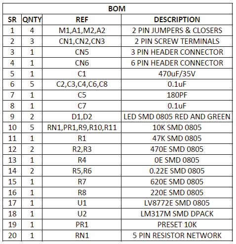
1 AUTHOR : RAJKUMAR SHARMA Applications Tiny Board has been designed around LV8772 IC from On-Semi. This driver is capable of micro-step drive and supports 4W 1-2 phase excitation. It has Low on Resistance with motor current selectable in four steps. The board is equipped with unusual condition warning LED and input Pulse Monitor LED. It is most suitable for the drive of a stepping motor for OA, amusements, hobby CNC, 3D printers, automatic machines, linear guides, motion control systems, XY gantry, Camera focus and zoom controller, Mini camera Pan Tilt Head. Slot Machine Vending Machine Cash Machine PPC (Plain Paper Copier) LBP (Laser Beam Printer) Scanner CNC 3D Printers Textile Camera Pan Tilt Head Camera Focus and Zoom Controller Features Power Supply input 9V to 30V (Max 32V) Output Current 2.5Amps Very low noise and smooth operations Very low noise in slow speed Low on resistance (Total of upper and lower: 0.55ohms) Micro-Step mode can be set to Full-Step, 1/2 Step,1/4,1/16 Steps Motor Current selectable in four steps Output short circuit protection circuit incorporated (IC) Built in thermal shutdown circuit No Control power supply required Input Signals 1. Step (Clock) 2. Direction 3. Enable 4. Reset This Drive default set to enable and reset Current Setting via onboard Preset (Potentiometer) Attenuation ATT1 and ATT2 by Jumpers Two Jumpers for Micro-Step settings On-Board Fault Warning LED On-Board Pulse Input indication LED INDIA AUTHOR RAJKUMAR SHARMA
2 koteq.com
3


4 5V DC OUT ENABLE DIRECTION PULSE GROUND RESET M1-MICRO STEPPING M2-MICRO STEPPING ATT1 ATT2 FAULT LED MONITOR
5 Chip Enable Functions (Default this pin set to high for normal operation) ST Pin High Operation Mode, Low Disable the drive This IC is switched between standby and operating mode by setting the ST pin, In standby mode, the IC is set to power-save mode and all logic is reset. In addition, the internal regulator circuit and charge pump circuit do not operate in standby mode. Position Detection Monitoring Function ( LED MO, D2) When the excitation position is in the initial position, the Monitor output LED MO D2 placed in the ON State Setting Constant-Current control reference current (PR1 Potentiometer) Potentiometer PR1 is to set the Current RESET Function (Default This Pin set to normal operation using pull down resistor R10) Reset Pin Low = Normal Operation, Reset Pin High = Reset State When The RST pin is set to High, the excitation position of the output is forcibly set to the initial state, and the Moni -D2 LED is in ON state, When RST is set to low, the excitation position is advanced by the next STEP input Output Short Circuit Output Short-Circuit protection type of IC is latch type to turn off when the output current exceeds the detection current and the state is maintained. The output short-circuit protection circuit is activated in and event of short-circuit in the output pin. When the short-circuit state continues for a period of time set by the internal timer (approximately 4uS), the output in which short-circuit was first detected are switched to the standby mode, And if the short-circuit state is still detected, all the outputs of the channel are switched to the standby mode, and the state is held, this state is released by setting ST to low. EMO Unusual Condition Warning Output Pin (Fault LED D1) This board is provided with EMO (Fault LED) which notifies the CPU of an unusual condition if the protection circuit operates by detecting an unusual condition of the IC, When an unusual condition is detected, the Fault LED D1 is placed in the ON (EMO=Low) Chopping Frequency F-Chop 10uA/180PF/).5VX2=55Khz Connections CN1: Power Supply In CN2: Bipolar Stepper Motor Connections CN6: Control Signal Inputs ( All inputs are TTL Level) Pin1 5V : DC Aux ( Output) Pin 2 ENB : Enable ( Default set to Enable, Required low input (Pull Down) to disable) Pin3 CK : Clock input to excite the motor ( Pulse Inputs) Pin 4 : GND Ground Signal Pin5 : RS : Reset input PR1: Onboard Preset (Potentiometer) to set the Current D1 : Fault LED D2 : Pulse Monitor LED CN5 : Aux. Power Supply Output, Supply 24V, 5V Regulated, Ground M1, M2 : Jumpers to set the Micro-stepping A1,A2: To Set the Motor Holding Current (A1=ATT1, A2=ATT2) MICRO-STEP SETTINGS SR M1 M2 Micro-Step RESOLUTION 1 LOW LOW FULL STEP 2 HIGH LOW HALF STEP 3 LOW HIGH QUARTER STEP 4 HIGH HIGH 1/16 STEP JUMPER CLOSED=LOW I JUMPER OPEN= HIGH Current Setting Reference Voltage Attenuation Ratio (A1 & A2 Closed= Low, Open=High) ATT1-A1 Low, ATT2-A2 Low = 100% ATT1-A1 High I ATT2-A2 Low = 80% ATT1-A1 Low I ATT2-A2 High = 50% ATT1-A1 High I ATT2-A2 High = 20% The formula used to calculate the output current when using the function for attenuating the VREF input voltage is giving bellow I out+(vref/%)x(attenuation Ratio)/RF resistance Example: At VREF of 1.0V, a reference voltage setting of 100% (ATT1-A1=Low ATT2-A2=Low) and an RF resistance of 0.5 Ohms, the output current is set as shown bellow, I-Out=1.0VX5X100%/0.22Ohms=0.91A If, in this state (ATT1-A1=High, ATT2-A2=High), I-Out will be as follows: I-Out =0.91AX50%=455Ma In this way, the output current is attenuated when the motor holding current is supplied so that power can be conserved.
LCMM024: DRV8825 Stepper Motor Driver Carrier,
 LCMM024: DRV8825 Stepper Motor Driver Carrier, High Current The DRV8825 stepper motor driver carrier is a breakout board for TI s DRV8825 microstepping bipolar stepper motor driver. The module has a pinout
LV8726TAGEVK Evaluation Kit User Guide
 LV8726TAGEVK Evaluation Kit User Guide 06/17/15 1 www.onsemi.com NOTICE TO CUSTOMERS The LV8726TA Evaluation Kit v0 is intended to be used for ENGINEERING DEVELOPMENT, DEMONSTRATION OR EVALUATION PURPOSES
A4988 Stepper Motor Driver Carrier with Voltage Regulators
 1 of 6 12/2/2011 6:37 PM A4988 Stepper Motor Driver Carrier with Voltage Regulators Pololu item #: 1183 26 in stock Price break Unit price (US$) 1 19.95 10 17.95 100 13.97 Quantity: backorders allowed
A4988 Stepper Motor Driver Carrier
 A4988 Stepper Motor Driver Carrier A4983/A4988 stepper motor driver carrier with dimensions. Overview This product is a carrier board or breakout board for Allegro s A4988 DMOS Microstepping Driver with
A4988 Stepper Motor Driver Carrier, Black Edition
 A4988 Stepper Motor Driver Carrier, Black Edition A4988 stepper motor driver carrier, Black Edition, bottom view with dimensions. Overview This product is a carrier board or breakout board for Allegro
Me Stepper Driver. Overview
 Me Stepper Driver Overview The Me Stepper Motor Driver module is designed to precisely drive the bipolar stepper motor. When pulse signals are input into the stepper motor, it rotates step by step. For
Stepper 6 click. PID: MIKROE 3214 Weight: 26 g
 Stepper 6 click PID: MIKROE 3214 Weight: 26 g Stepper 6 click is the complete integrated bipolar step motor driver solution. It comes with the abundance of features that allow silent operation and optimal
Routout CNC 3 Axis Plug & Play Controller Data Sheet Version 1.1
 Routout CNC 3 Axis Plug & Play Controller Data Sheet Version 1.1 The Routout CNC 3 Axis stepper motor drive box has many uses including for CNC retrofitting / robot control or driving you own CNC machine.
XS-3525/8S-3. Standard Pinout Information. Single Supply (v1s) XØ YØ ZØ
 XØ YØ ZØ") XS-3525/8S-3 Single Supply (v1s) Standard Pinout Information XØ YØ ZØ The 26 pin header is configured to allow easy connection via ribbon cable to an IDC DB-25 connector. This facilitates direct connection
XS-3525/8S-3 Single Supply (v1s) Standard Pinout Information XØ YØ ZØ The 26 pin header is configured to allow easy connection via ribbon cable to an IDC DB-25 connector. This facilitates direct connection
MP6500 Stepper Motor Driver, Digital Current Control
 This breakout board for the MPS MP6500 micro stepping bipolar stepper motor driver is Pololu s latest stepper motor driver. The module has a pinout and interface that are very similar to that of our popular
LV8414CSGEVK V1.0 Evaluation Kit User Guide
 LV8414CSGEVK V1.0 Evaluation Kit User Guide 03/25/2016 1 www.onsemi.com NOTICE TO CUSTOMERS The LV8414CS Evaluation Kit is intended to be used for ENGINEERING DEVELOPMENT, DEMONSTRATION OR EVALUATION PURPOSES
Octagon Systems Corporation, the Octagon logo, the Micro PC log and Micro PC are trademarks of Octagon Systems Corporation.
 5974 PC 104 Card COPYRIGHT Copyright 1993 Octagon Systems Corporation. All rights reserved. However, any part of this document may be reproduced provided that Octagon Systems Corporation is cited as the
USER S MANUAL. C32- DUAL PORT MULTIFUNCTION CNC BOARD Rev. 4
 USER S MANUAL C32- DUAL PORT MULTIFUNCTION CNC BOARD Rev. 4 August, 2012 USER'S MANUAL TABLE OF CONTENTS Page # 1.0 FEATURES... 1-1 2.0 SPECIFICATIONS... 2-3 3.0 BOARD DESCRIPTION... 3-4 4.0 FUNCTIONAL
User's Manual. For ST-6560V3. Version All Rights Reserved
 User's Manual For ST-6560V3 Version 2.0 2016.08.25 All Rights Reserved 1. Key Features Toshiba TB6560AHQ chip - High power, maximum current 3.5A Resolution 1, 1/2, 1/8, 1/16 micro stepping output Working
BSH-DRV-1 Bass Shaker Driver Data Sheet (V0.4) BFF Design Ltd
 BFF Design Ltd") BSH-DRV-1 Bass Shaker Driver Data Sheet (V0.4) BFF Design Ltd 1. Introduction The BFF BSH-DRV-1 card is a direct driver for bass shakers (vibration transducers). It provides vibration/rumble effects for
BSH-DRV-1 Bass Shaker Driver Data Sheet (V0.4) BFF Design Ltd 1. Introduction The BFF BSH-DRV-1 card is a direct driver for bass shakers (vibration transducers). It provides vibration/rumble effects for
PP-BOB2-V1.0 PARALLEL PORT BREAKOUT BOARD
 PP-BOB2-v1 PARALLEL PORT BREAKOUT BOARD Document: Operation Manual Document #: T17 Document Rev: 2.0 Product: PP-BOB2-v1.0 Product Rev: 1.0 Created: March, 2013 Updated: Dec, 2014 THIS MANUAL CONTAINS
Instruction Manual for BE-SP3 Circuit. 10/21/07
 Page 1 of 54 Instruction Manual for BE-SP3 Circuit. 10/21/07 Page 1 Index: Page 2 BE-SP3 Circuit Specifications. Page 3-4 Intro to the BE-SP3. Page 5 Basics of serial to parallel. Page 6-7 ASCII Code.
Preliminary Datasheet MX Axis Stepper Drive with Breakout Board & I/O s. Preliminary V1.0
 Preliminary Datasheet MX4660 4-Axis Stepper Drive with Breakout Board & I/O s Preliminary V1.0 Features Power up to 4 stepper motors of NEMA 17, 23, 24, or 34 Sophisticated stepper motor control based
G540 4-AXIS DRIVE REV 4: MAY 28, 2010
 Thank you for choosing to purchase the G540 4-Axis Drive System. If you are dissatisfied with it for any reason at all within two weeks of its purchase date, you may return it for a full refund provided
PARAMETER CONDITIONS MIN TYP MAX UNITS Input Supply Range V I VIN Shutdown Current LEDEN = LOW 3 8 µa I VIN Operating Current.
 DESCRIPTION WARNING! Do not look directly at operating LED. This circuit produces light that can damage eyes. Demonstration circuit 1187 is an RGB LED Driver and Charge Pump featuring the LTC3212. DEMO
HDBB Breakout board user s manual
 HDBB Breakout board user s manual The HDBB breakout board was designed to use with our Whale2(-T)*, Whale3, Mammut* and Dugong servo drives or with any other third party stepper or servo drives which using
Datasheet MX Axis Stepper Drive with Breakout Board & I/O s. Version1.0
 Datasheet MX3660 3-Axis Stepper Drive with Breakout Board & I/O s Version1.0 1. Features Power up to 3 stepper motors of NEMA 17, 23, 24, or 34 Sophisticated stepper motor control based on latest DSP technology
Reversible motor driver
 Reversible motor driver The BA6286 and BA6286N are reversible-motor drivers with a maximum output current of 1.0A. Two logic inputs allow four output modes: forward, reverse, stop (idling), and brake.
USER S MANUAL. C11S- MULTIFUNTCION CNC BOARD Rev. 1.2
 USER S MANUAL C11S- MULTIFUNTCION CNC BOARD Rev. 1.2 SEPTEMBER 2014 User s Manual Page i TABLE OF CONTENTS Page # 1. Overview... 1 2. Features... 1 3. Specifications... 3 4. BOARD DESCRIPTION... 4 5. Special
USER S MANUAL. C11- MULTIFUNTCION CNC BOARD Rev. 9.9
 USER S MANUAL C11- MULTIFUNTCION CNC BOARD Rev. 9.9 FEBRUARY, 2015 User s Manual Page i TABLE OF CONTENTS Page # 1. Overview... 1 2. Features... 1 3. Specifications... 3 4. BOARD DESCRIPTION... 4 5. Special
Datasheet MX Axis Stepper Drive with Breakout Board & I/O s. Version
 Datasheet MX4660 4-Axis Stepper Drive with Breakout Board & I/O s Version 1.0 http://www.leadshine.com http://www.leadshineusa.com 2014 Leadshine Technology Co., Ltd. Notice This document is not for use
4-Axis TB6560 CNC Driver Board Users Manual. 1.1 Scope General Description Photo of 4-AXIS CNC Board Key Features...
 Content 4-Axis TB6560 CNC Driver Board Users Manual 1. General Information... 2 1.1 Scope... 2 1.2 General Description... 2 2. Descriptions of 4-AXIS CNC Board... 2 2.1 Photo of 4-AXIS CNC Board... 2 2.2
MSD325 Microstepping Drive
 MSD325 Microstepping Drive Introduction MSD325 is a very small size microstepping drive based on most advanced technology in the world today. It is suitable for driving any 2-phase and 4-phase hybrid stepper
Answers to Chapter 2 Review Questions. 2. To convert controller signals into external signals that are used to control the machine or process
 Answers to Chapter 2 Review Questions 1. To accept signals from the machine or process devices and to convert them into signals that can be used by the controller 2. To convert controller signals into
BB-303 Manual Baseboard for TMCM-303
 BB-303 Manual Baseboard for TMCM-303 Trinamic Motion Control GmbH & Co. KG Sternstraße 67 D 20357 Hamburg, Germany http://www.trinamic.com BB-303 Manual (V1.04 / Jul 9th, 2007) 2 Contents 1 Features...
UNIPORT V2. Uniport V2
 UNIPORT V2 Uniport V2 USB powered Parallel port interconnection board with optical isolated inputs, buffered outputs, charge pump interlock and power relays Specification Full optical isolation of all
USER S MANUAL VER.1. C10D- PARALLEL PORT INTERFACE CARD BOARD Rev. 1
 USER S MANUAL VER.1 C10D- PARALLEL PORT INTERFACE CARD BOARD Rev. 1 MARCH 2018 User s Manual Page i USER'S MANUAL TABLE OF CONTENTS Contents Page # 1.0 OVERVIEW... iii 2.0 FEATURES... iii 3.0 SPECIFICATIONS...
Reversible motor driver
 Reversible motor driver The BA6289F and BA6417F are reversible-motor drivers, with an output current of 600mA for the former and 1A for the latter. Two logic inputs allow four output modes: forward, reverse,
Variable Power Supply Digital Control Circuit Diagram Using Lm317
 Variable Power Supply Digital Control Circuit Diagram Using Lm317 DIGITAL POWER SUPPLY USING LM317 A Major Project Report Submitted partial fulfillment of the requirement for the award of the Degree of
USER S MANUAL VER.1. C10- PARALLEL PORT INTERFACE CARD BOARD Rev. 11
 USER S MANUAL VER.1 C10- PARALLEL PORT INTERFACE CARD BOARD Rev. 11 FEBRUARY, 2017 User s Manual Page i USER'S MANUAL TABLE OF CONTENTS Contents Page # 1.0 OVERVIEW... iii 2.0 FEATURES... iii 3.0 SPECIFICATIONS...
MSD980 Microstepping Drive
 MSD980 Microstepping Drive Introduction MSD980 is a high-performance microstepping drive based on most advanced technology in the world today. It is suitable for driving any 2-phase and 4-phase hybrid
D115 The Fast Optimal Servo Amplifier For Brush, Brushless, Voice Coil Servo Motors
 D115 The Fast Optimal Servo Amplifier For Brush, Brushless, Voice Coil Servo Motors Ron Boe 5/15/2014 This user guide details the servo drives capabilities and physical interfaces. Users will be able to
Blue Point Engineering
 Blue Point Engineering Board - Pro Module (E) Instruction Pointing the Way to Solutions! Controller I Version 2.1 The Board Pro E Module provides the following features: Up to 4 minutes recording time
TLE9869 Eval.Kit V1.0 Users Manual
 TLE9869 Eval.Kit V1.0 Users Manual Contents Abbreviations... 2 1 Concept... 3 2 Interconnects... 4 3 Test Points... 5 4 Jumper Settings... 6 5 Communication Interfaces... 7 5.1 LIN (via Banana jack and
G540 User Manual. Date Modified: March 5, 2012 Page 1 of 10
 G540 User Manual Date Modified: March 5, 2012 Page 1 of 10 DIMENSIONS PHYSICAL AND ELECTRICAL RATINGS Minimum Maximum Units Supply Voltage 18 50 VDC Motor Current 0 3.5 A Power Dissipation 1 13 W Short
CNC Shield Guide V
 CNC Shield Guide V1.0 12 2018 Maker Group Global LLC 2018 Safety Statement The author of this document is not liable or responsible for any accidents, injuries, equipment damage, property damage, loss
Stepper Motor Driver Board. Instruction Note
 Stepper Motor Driver Board Instruction Note August 31, 2012 General Photonics Corp. Ph: (909) 590-5473 5228 Edison Ave. Fax: (909) 902-5536 Chino, CA 91710 USA www.generalphotonics.com Document #: GP-IN-MDL-003-CONTROLB-10
DMX-K-DRV. Integrated Step Motor Driver + (Basic Controller) Manual
 Manual") DMX-K-DRV Integrated Step Motor Driver + (Basic Controller) Manual Table of Contents 1. Introduction... 4 Features... 4 2. Part Numbering Scheme... 5 3. Electrical and Thermal Specifications... 6 Power
DMX-K-DRV Integrated Step Motor Driver + (Basic Controller) Manual Table of Contents 1. Introduction... 4 Features... 4 2. Part Numbering Scheme... 5 3. Electrical and Thermal Specifications... 6 Power
CEIBO FE-5111 Development System
 CEIBO FE-5111 Development System Development System for Atmel W&M T89C5111 Microcontrollers FEATURES Emulates Atmel W&M T89C5111 4K Code Memory Real-Time Emulation and Trace Frequency up to 33MHz/5V ISP
SmartFan Vortex. I2C Speed Control for 12 VDC Fans CONTROL RESOURCES INCORPORATED. The driving force of motor control & electronics cooling.
 The driving force of motor control & electronics cooling. SmartFan Vortex I2C Speed Control for 12 VDC Fans DC Controls P/N VOR5I400F SmartFan Vortex is an I2C fan speed control and alarm designed for
TECHNICAL REFERENCE BSD V-3A Bipolar Stepper Driver
 TECHNICAL REFERENCE BSD 3630 36V-3A Bipolar Stepper Driver Contents Chapter 1 Safety Precautions.. 3 Chapter 2 Drive Overview...4 2.1 Key Features...4 2.2 Drive Description...4 2.3 Applications. 4 Chapter
CNC4X35A 4 axis Stepper Motor Control Board
 CNC4X35A 4 axis Stepper Motor Control Board Just connect bipolar stepper motors, power and a parallel port signal source CNC4X35A 4 axis Stepper Motor Control Board Specs: Designed for easy construction/retrofit
USER S MANUAL. C35S- QUICK SETUP BREAKOUT BOARD Rev. 1.3
 USER S MANUAL C35S- QUICK SETUP BREAKOUT BOARD Rev. 1.3 FEBRUARY, 2015 USER'S MANUAL TABLE OF CONTENTS Page # Contents 1.0 OVERVIEW... 1 2.0 FEATURES... 1 3.0 SPECIFICATIONS.... 2 4.0 BOARD DESCRIPTION...
DLA. DMX512 Analyzer. DLA Users Manual SV2_00 B.lwp copyright ELM Video Technology, Inc.
 DLA DMX512 Analyzer DLA DLA-HH 1 Table Of Contents IMPORTANT SAFEGUARDS... 2 DLA OVERVIEW... 3 CONNECTION... 3 OPERATION... 3 HARDWARE SETUP... 4 DLA-HH (PORTABLE) LAYOUT... 4 CHASSIS LAYOUT... 4 DLA MENU
PP-BOB2-V2.0 PARALLEL PORT BREAKOUT BOARD
 PP-BOB2-V2 PARALLEL PORT BREAKOUT BOARD Document: Operation Manual Document #: T18 Document Rev: 1.0 Product: PP-BOB2-V2.0 Product Rev: 1.0 Created: October, 2015 THIS MANUAL CONTAINS INFORMATION FOR INSTALLING
DMX-K-DRV Integrated Step Motor Driver Manual
 Tu Sitio de Automatización! DMX-K-DRV Integrated Step Motor Driver Manual Table of Contents 1. Introduction... 4 2. Part Numbering Scheme... 4 3. Dimensions... 5 NEMA 11 DMX-K-DRV... 5 NEMA 17 DMX-K-DRV...
MS483 MICROSTEPPING DRIVE
 Specialists in custom precision motion control MS483 MICROSTEPPING DRIVE High Performance, customizable microstepping drive. Vertex Linears MS483 is a high performance, low cost microstepping drive that
G540 MANUAL MULTIAXIS STEP MOTOR DRIVE
 G540 MANUAL MULTIAXIS STEP MOTOR DRIVE PRODUCT DIMENSIONS PHYSICAL AND ELECTRICAL RATINGS Minimum Maximum Units Supply Voltage 18 50 VDC Motor Current 0 3.5 A Power Dissipation 1 13 W Short Circuit Trip
SDM / 4 Phase Stepper Drive Module. Compact Size & High Power Density, 20-60VDC, 6A Peak. Version 1.0
 SDM660 2 / 4 Phase Stepper Drive Module Compact Size & High Power Density, 20-60VDC, 6A Peak Version 1.0 http://www.leadshine.com / http://www.leadshineusa.com 2013 Leadshine Technology Co., Ltd. 3/F,
C10S- PARALLEL PORT INTERFACE CARD Rev. 1.4
 USER S MANUAL VER.1 C10S- PARALLEL PORT INTERFACE CARD Rev. 1.4 SEPTEMBER, 2016 User s Manual Ver.1 Page i USER'S MANUAL TABLE OF CONTENTS Page # 1. OVERVIEW... 1 2. FEATURES... 1 3. SPECIFICATIONS...
Allegra Series Reference Manual. Programmable Motion Control System
 Allegra Series Reference Manual Programmable Motion Control System The Allegra series of motion controllers are stand-alone or host controlled, easy-to-use, plug-and-play and cost effective solutions for
CHAPTER 4 I/O PORT PROGRAMMING
 CHAPTER 4 I/O PORT PROGRAMMING I/O Port Pins The four 8-bit I/O ports P0, P1, P2 and P3 each uses 8 pins All the ports upon RESET are configured as input, ready to be used as input ports When the first
Technical Information Stepper Motor Card >HP-Step.pro< Rev. 2.0 (last updated )
") Dipl.-Ing. Thorsten Ostermann Technical Information Stepper Motor Card >HP-Step.pro< Rev. 2.0 (last updated 1.3.2006) Functional Description HP-Step.pro is a 1 channel stepping motor driver board that
Dipl.-Ing. Thorsten Ostermann Technical Information Stepper Motor Card >HP-Step.pro< Rev. 2.0 (last updated 1.3.2006) Functional Description HP-Step.pro is a 1 channel stepping motor driver board that
ST400C-NT USER S GUIDE. Table of Contents
 ST400C-NT USER S GUIDE Table of Contents Board Overview Block Diagram Disclaimer Introduction Features 1 Quick Start 2 Function Description Host Interface and Communication with PC's 3 Networking Operation
Keywords Digital IC tester, Microcontroller AT89S52
 Volume 6, Issue 1, January 2016 ISSN: 2277 128X International Journal of Advanced Research in Computer Science and Software Engineering Research Paper Available online at: www.ijarcsse.com Digital Integrated
DSP-BASED MOTOR CONTROLLER FOR THREE-PHASE BRUSHLESS DC MOTORS
 DSP-BASED MOTOR CONTROLLER FOR THREE-PHASE BRUSHLESS DC MOTORS FEATURES / BENEFITS Embedded Motor Control DSP (ADMCF328) improves higher level system integration and flexibility 7A phase current (cycle-by-cycle
Chapter 5 SDM-20240/20242
 Chapter 5 SDM-20240/20242 Introduction The SDM-20240 and SDM-20242 are stepper driver modules capable of driving up to four bipolar two-phase stepper motors. The current is selectable with options of 0.5,
C23- DUAL PORT MULTIFUNCTION CNC BOARD Rev. 3.1
 C23- DUAL PORT MULTIFUNCTION CNC BOARD Rev. 3.1 User manual Rev. 2 1. Overview This card has been designed to provide a flexible interface and functions to computer CNC projects, by using the parallel
Hardware Installation Manual MX Axis Stepper Drive with Breakout Board & I/O s
 Hardware Installation Manual MX3660 3-Axis Stepper Drive with Breakout Board & I/O s Version 1.0 11 / 2013 Hardware Manual for MX3660 3-Axis Stepper Drive with Breakout Board & I/O s ii Notice Read this
USER S MANUAL VER.1. C11G- MULTIFUNTCION CNC BOARD Rev. 9
 USER S MANUAL VER.1 C11G- MULTIFUNTCION CNC BOARD Rev. 9 MARCH, 2017 User s Manual Page i USER'S MANUAL TABLE OF CONTENTS Contents Page # 1.0 OVERVIEW... 1 2.0 FEATURES... 1 3.0 SPECIFICATIONS... 2 4.0
MIC706P/R/S/T, MIC708R/S/T
 MIC706P/R/S/T, MIC708R/S/T µp Supervisory Circuit General Description The MIC706 and MIC708 are inexpensive microprocessor supervisory circuits that monitor power supplies in 3.0 and 3.3 microprocessor-based
MINITRONICS v1.0 DATASHEET
 MINITRONICS v. DATASHEET Author Bart Meijer Date 2th of April 23 Document version. ReprapWorld.com PRODUCT OVERVIEW Minitronics is the latest development of ReprapWorld.com. It's designed to be an easy
3 axes stepper motor driver board. Slider SFX. Upgrading milling and turning machines to CNC machines by use of stepper motors. User guide SFX Page 1
 3 axes stepper motor driver board Slider SFX Upgrading milling and turning machines to CNC machines by use of stepper motors User guide SFX Page 1 Copyright Thorsten Ostermann, 2008 The present stepper
Brushless DC Motor Controller Product Specification Assembly 025F0219
 Product Specification Assembly Revision History ECN # Date Rev Description By EC46310 6/14/12 A Initial Release Z. Sheu EC63683 01/27/15 B Correct interface connector part number D. Stahl EC81620 11/15/17
AXBB-E ethernet motion controller and breakout board user's guide
 AXBB-E ethernet motion controller and breakout board user's guide Version of this document: 1.0002 1/29 Contents 1.Description of the AXBB-E device. 2.Safety notes. 3.Physical installation of the device.
TB6600 Stepper Motor Driver
 TB6600 Stepper Motor Driver V1.0 07 2018 Open Source Mechatronics LTD 2018 Safety Statement The author of this document is not liable or responsible for any accidents, injuries, equipment damage, property
Flomatic Smart Card TM Model FDHC-100 (Digital High-Resolution Controller) Configuration and Operation Manual
 Configuration and Operation Manual") The Flomatic FDHC-100 is a high performance Digital positioner intended to control AC actuators, providing 450 points of resolution with quarter turn actuators ranging from 2 sec to 120 sec and rated for
The Flomatic FDHC-100 is a high performance Digital positioner intended to control AC actuators, providing 450 points of resolution with quarter turn actuators ranging from 2 sec to 120 sec and rated for
ADVANCED MICRO SYSTEMS
 Overview... 3 Included in the Box:... 3 Pinout... 4 Installation... 5 Power Supply... 6 Stepping Motors... 7 DIP Switch (JP1) Location... 8 Setting the Output Current (JP1)... 8 Microstep Resolution (JP1)...
3-Axis Stepper Drive Datasheet MX3660
 3-Axis Stepper Drive Datasheet MX3660 3-Axis Stepper Drive + Breakout Board, 20-60VDC, 6A Peak Version 0.0.2 http://www.leadshine.com Features Three individual stepper drive boards Suitable for NEMA17
LT900SERIES. 1xN Multi-Channel Switch Operation Manual
 LT900SERIES 1xN Multi-Channel Switch Operation Manual Table of Contents General Information.. 1 General Specifications...... 2 Interface Connectors..... 3 Connector Assignment 16 pin........ 4 26 pin....
AMPLIFIER PARALLEL INTERFACE SPECIFICATION
 AMPLIFIER PARALLEL INTERFACE SPECIFICATION INTRODUCTION A parallel interface connector is fitted at the rear of the amplifier. In multi-unit systems, all of the parallel interface connectors are bussed
RN-174 WiFly Super Module
 RN- WiFly Super Module Features Evaluation board for the RN- module Supports chip antenna (RN--C), PCB trace antenna (RN--P), wire antenna (RN--W), and U.FL connector for an external antenna (RN--U) Ultra-low
Replicape Rev B 3D printer controller board
 Replicape Rev B 3D printer controller board SKU 102991007 Description Replicape is a high end 3D printer electronics package in the form of a Cape that can be placed on a BeagleBone Black. This page is
Before powering on your driver, read this manual thoroughly. If you have any doubt or suggestion, please do not hesitate to contact us!
 Laser diode driver Datasheet & User Manual Before powering on your driver, read this manual thoroughly. If you have any doubt or suggestion, please do not hesitate to contact us! LLC, st. Sedova, 37, lit.
UNIPORT V3. C R H Electronics Design
 UNIPORT V3 V C R H Electronics Design Uniport V3 USB powered Parallel port interconnection board with optical isolated inputs, buffered outputs, charge pump interlock and power relays By C R Harding Specification
ELM185xB Laser Diode Driver
 General description Laser Diode Driver is a bipolar type laser diode driver IC with internal APC circuit which consists of a reference voltage source, an error amplifier, and a thermal shutdown circuit
4-channel driver and power controller
 4-channel driver and power controller The is a 4-channel driver and power supply that includes the reset, recharge, and shock detection circuits required for portable CD players on a single IC. The driver
4Trio Motion Technology3
 4Trio Motion Technology3 MC 202 Motion Controller Product Overview 3-1 3.0 Motion Coordinator 202 Description 3.1 Motion Coordinator 202 The Motion Coordinator 202 is a miniature stepper/servo positioner
Datasheet-MA860 Stepper Motor Driver
 Datasheet-MA860 Stepper Motor Driver Introduction The MA860 is an economical micro-stepping driver based on patented technology of EDRIVE. It is suitable for driving 2-phase and 4-phase hybrid stepping
ES-562/564U COMBINATION CLOCK/TIMER
 142 SIERRA ST., EL SEGUNDO, CA 90245 USA (310)322-2136 FAX (310)322-8127 www.ese-web.com ES-562/564U COMBINATION CLOCK/TIMER OPERATION AND MAINTENANCE MANUAL The ES-562U/564U is a combination six digit
Hardware Manual CNC760
 Hardware Manual CNC760 Revision 3 6 December, 2017 Released Copyright 2017 by Eding CNC History: Revision Date Author 1 22-5-2017 AB 2 23-6-2017 AB 3 6-12-2017 AB Revision overview: Revision Remarks 1
EMTRON AUSTRALIA EMTRON ECU OVERVIEW
 EMTRON AUSTRALIA EMTRON ECU OVERVIEW Table of Contents 1.0 General... 3 2.0 Injection... 4 3.0 Ignition... 5 4.0 Digital Inputs... 6 5.0 Auxiliary Outputs... 7 6.0 Analog Inputs... 9 7.0 Crank and Cam
Embedded Navigation Solutions VN 100, VN 200 & VN 300 Development Board User Manual
 Embedded Navigation Solutions VN 100, VN 200 & VN 300 Development Board User Manual VectorNav Technologies Contact Info 10501 Markison Road Phone +1 512 772 3615 Dallas, Texas 75238 Email support@vectornav.com
MIC705/706/707/708. General Description. Features. Applications. Typical Application. µp Supervisory Circuit
 µp Supervisory Circuit General Description The MIC705, MIC706, MIC707, and MIC708 are inexpensive microprocessor supervisory circuits that monitor power supplies in microprocessor-based systems. The circuit
SP336E Evaluation Board Manual Rev 2.1
 SP336E Evaluation Board Manual 11-23-10 Rev 2.1 Features Easy Evaluation of the SP336E Transceiver RS-232 and RS-485 Protocols Local or Remote Loop Back testing 10Mbps Differential Transmission Rates Test
Datasheet MX Axis Stepper Drive with Breakout Board & I/O s. Version
 Datasheet MX3660 3-Axis Stepper Drive with Breakout Board & I/O s Version 1.1 http://www.leadshine.com http://www.leadshineusa.com 2013 Leadshine Technology Co., Ltd. Notice This manual is not for use
SmartFan Cirrus-9. Speed Control and Alarm for 4-Wire Fans CONTROL RESOURCES INCORPORATED. The driving force of motor control & electronics cooling.
 SmartFan Cirrus-9 Speed Control and larm for 4-Wire Fans The driving force of motor control & electronics cooling. P/N 4WR9C00-F DC Controls SmartFan Cirrus-9 is a digital fan speed control and alarm that
ASI. Switched-Capacitor Boost Converter 3.3V-5.0V 100mA GENERAL DESCRIPTION FEATURES APPLICATIONS
 ASI Technical Data Sheet Switched-Capacitor Boost Converter 3.3V-5.0V 100mA FEATURES Switched-Capacitor Step-Up Operation Input Range: 2.7V to 5.0V Output Voltage: 3.3V-5.0V (programmable) Output Current:
AN004 Using the PMDX-126 s Error Input and Restart Output with Geckodrive Servo Drivers and Mach3 CNC Software
 1.0 Overview This application note describes how to connect the to the Geckodrive G320//G340 step servo driver s ERR/RST terminal to allow the to detect a Geckodrive error (fault) state and to reset the
PLCIO2 Programmable Logic Controller Updated 3/26/10
 Overview: PLCIO2 Programmable Logic Controller Updated 3/26/10 PLCIO2 is a programmable logic controller which provides: 35 Inputs (bipolar, with a choice of 5 or 24) 39 Outputs (20SPST, 2 SPDT, 17 open
Before powering on your driver, read this manual thoroughly. If you have any doubt or suggestion, please do not hesitate to contact us!
 Laser diode driver Datasheet & UserManual Before powering on your driver, read this manual thoroughly. If you have any doubt or suggestion, please do not hesitate to contact us!, 37 Sedova St, Off 209,
Helix Semiconductors HS200 Data Sheet
 HS200 +48Vin 15W DC-DC MuxCapacitor Power IC The Helix Semiconductor HS200 DC-DC MuxCapacitor Power IC offers the highest energy efficiency per density. When used with a low cost POL regulator, system
Brushless DC Motor Controller Product Specification Assembly 025F0200
 Product Specification Assembly 025F0200 Revision History ECN # Date Rev Description By EC40382 071811 A Initial Release D. Stahl EC81620 11/15/17 B Added Agency Approval S. Lavey Page 1 of 11 Table Of
Pin # Name Type Description
 Figure 1. Photo of Actual FEATURES High Efficiency: 90% Constant Current Output Maximum Output Current: 3A Current Output Noise: 0.0% High Stability: 0ppm/ C PWM Switching Frequency Synchronizable Zero
Motionnet G9004. User's Manual. (CPU emulation device) Nippon Pulse Motor Co., Ltd.
 Nippon Pulse Motor Co., Ltd.") Motionnet G9004 (CPU emulation device) User's Manual Nippon Pulse Motor Co., Ltd. [Preface] Thank you for considering our super high-speed serial communicator LSI, the "G9000." To learn how to use the
Motionnet G9004 (CPU emulation device) User's Manual Nippon Pulse Motor Co., Ltd. [Preface] Thank you for considering our super high-speed serial communicator LSI, the "G9000." To learn how to use the