UNIPORT V2. Uniport V2
|
|
|
- Brandon Bridges
- 5 years ago
- Views:
Transcription

1 UNIPORT V2 Uniport V2
2 USB powered Parallel port interconnection board with optical isolated inputs, buffered outputs, charge pump interlock and power relays Specification Full optical isolation of all inputs. Four XYZA Axis buffered outputs to stepper control boards. Integrated Charge pump logic line protects all outputs. High current (30mA max) stepper drive outputs with charge pump interlock. LED status indicators for Power, CP, Relays 1&2. USB type B computer power socket Charge pump override jumper Mainly surface mount components for greater reliability. Board size 107 X 80 mm. FR4, Immersion gold, 1oz copper, RoHS compliant. Two 16A, 240V AC control relays with single pole contacts. Input power jumpers for different configurations. Alternative 5 volt input power connection. Only consumes 150mA with all relays activated. Manual V2.0 March 09 Hardware V2.0 March 09 Introduction As quite a few stepper driver boards now have built in optical isolation but need a reasonable amount of drive current, a product was needed to interface with these driver boards. The Uniport board addresses this problem by providing high current drive for all stepper signals with charge pump control for maximum protection and high frequency performance for very fine step rates. Four axis, step and direction signals are available and five inputs to the board which are optically isolated with optional power jumpers provided to configure as desired. To simplify power requirements the whole board can be powered from a standard computer USB port or an external regulated 5 volt
3 DC connection if available. For power switching motors, pumps etc the Uniport board is equipped with two 16 Amp power relays that also have charge pump interlock protection. Description The Uniport board is an optical isolated input parallel breakout board with the addition of a charge pump, power save circuits and relay control outputs. All stepper drive outputs are buffered with up to 30mA of drive current and a high frequency operation making them ideal to drive optically isolated stepper boards. Unlike the basic parallel brake-out boards the Uniport board has designated X, Y, Z & A motor control step and direction pins that will need to be matched in the user software. All these step and direction signals are actually treated the same way in hardware and can be made interchangeable if there is no software option. The chart fig1 gives the pinout reference used in the design. The Charge pump circuit uses the 12 KHz signal configured to pin one of the parallel port generated by the CNC software when the program is up and running correctly. The logic level obtained from this signal controls either an enable or sleep pin on the stepper motor drive board or boards. There is a charge pump override jumper J13. This can be used for test purposes or connected permanently if your software does not support a charge pump signal. The charge pump signal is gated into the buffer chips so that they are disabled without this signal present. This means that driver boards that have no enable signal pins are still made safe by having there input signals removed. This charge pump signal is also gated into all relay outputs so no false triggering of the relays can occur while the software is not running. The Uniport board has five signal inputs each with its own series limiting resistor. The resistor value is set to give 5mA current through the device on a 5V supply. The input ports 1-3 have their limiting resistors connected to the external 5 volt pin which can be linked across to the internal 5V line with jumper L3. Jumper L2 also links the boards ground to the 0V terminals. With both links in position you can wire switches between input and ground with no external component. This of course bypasses the full isolation afforded by the opto-isolators. Inputs 4 & 5 are totally independent and need an external 5V signal to operate them unless you link wires from the other terminals. Fig 2 shows how the inputs are arranged. If you wish to use a 12V signal on these inputs then an additional resistor of 1.8K ohms in series with the input will be required. Notes : The control software must have the charge pump signal set to pin1 and be present for the board to be enabled unless the override link is on.
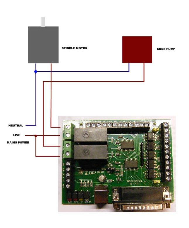
4 Fig1 Parallel Port Pin Uniport Output Input/Output 1 Charge pump signal Out 2 X Direction Out 3 X Step Out 4 Y Direction Out 5 Y Step Out 6 Z Direction Out 7 Z Step Out 8 A Direction (4 th Axis) Out 9 A Step (4 th Axis) Out 10 Input 1 (isolated) In 11 Input 2 (isolated) In 12 Input 3 (isolated) In 13 Input 4 (isolated) In 15 Input 5 (isolated) In 14 Output Out (SP) 16 Relay1 Out (SP) 17 Relay2 Out (SP) computer ground Ground reference Connections You will need two cables from your computer to the Uniport board. A standard parallel port 25 way male to female lead provides all the signal information. A standard USB A to B lead provides a 5 volt power supply for the Uniport board. Alternatively there is a 5 volt power connection available. This voltage must be a regulated 5V DC supply. A system wiring setup to a DRV25DUAL board is shown in Fig 3. Fig4 shows a simple limit switch serial circuit and emergency stop switch using two inputs to the Uniport board. All micro switches are normally closed connection. Configure controlling software to stop on change of input signal pin parallel port (11) and limit switches on pin (10). Other inputs could be used for home switches or separate banks of limit switches for each axis. The software manual usually describes these functions in more detail. Fig5 shows connecting relay output one to controlling spindle motor and relay two a coolant pump. The pump or motor is simply connected to the normally open connection RLYA and power applied to the RLYB common. Activating
5 the relay closes the contacts completing the circuit. Utmost care should be taken handling the Uniport board when there are live mains connections connected to the PCB as the relay terminals are exposed on the underside of the board. It is better to bolt the board down to the case or a side panel with a small gap to stop fingers being inserted underneath. Fig 2 Opto isolator input connections Fig3 Connecting DRV25DUAL to UNIPORT

6 Repeat as required for further Axis. Only one 5volt lead needs to be connected enable and PS will need to be common between boards. Fig4 Input wiring.

7 With links in position, inputs four and five are still fully isolated from power and ground.
8 Fig5 Relay connections
9 Dimensions
UNIPORT V3. C R H Electronics Design
 UNIPORT V3 V C R H Electronics Design Uniport V3 USB powered Parallel port interconnection board with optical isolated inputs, buffered outputs, charge pump interlock and power relays By C R Harding Specification
HDBB Breakout board user s manual
 HDBB Breakout board user s manual The HDBB breakout board was designed to use with our Whale2(-T)*, Whale3, Mammut* and Dugong servo drives or with any other third party stepper or servo drives which using
CNC4PC. MULTIFUNCTION CNC BOARD Rev2
 CNC4PC Manual MULTIFUNCTION CNC BOARD Rev2 Overview This card has been designed to provide a flexible interface and functions to your computer projects, by using the parallel port control software. This
IO3-R2 BREAKOUT BOARD
 IO3-R2 BREAKOUT BOARD DESCRIPTION Breakout board IO3-R2 (Revision R2) has digital buffer for STEP/DIR/ENA command signals and as such it is particularly suitable for the connection up to 4 microstep drives
Manual. Model#-DB25M-3R6A. 6 Axis CNC Interface Breakout Board. Lastest update : Feb Store this manual away for further reference.
 Manual 6 Axis CNC Interface Breakout Board Model#-DB25M-3R6A Lastest update : Feb 2016 Read this manual carefully before making connections to the board. Store this manual away for further reference. Safety
PP-BOB2-V1.0 PARALLEL PORT BREAKOUT BOARD
 PP-BOB2-v1 PARALLEL PORT BREAKOUT BOARD Document: Operation Manual Document #: T17 Document Rev: 2.0 Product: PP-BOB2-v1.0 Product Rev: 1.0 Created: March, 2013 Updated: Dec, 2014 THIS MANUAL CONTAINS
CNC4PC. C11G - MULTIFUNCTION CNC BOARD Rev. 5.4
 CNC4PC Manual C11G - MULTIFUNCTION CNC BOARD Rev. 5.4 Overview This card has been designed to provide a flexible interface and functions to your computer projects, by using the parallel port control software.
PMDX-105. I/O Option Riser Board User s Manual. Document Revision: 1.1 Date: 7 September 2004 PCB Revision: PCB-443A
 PMDX-105 I/O Option Riser Board User s Manual Date: 7 September 2004 PMDX Web: http://www.pmdx.com 7432 Alban Station Blvd., A105 Phone: +1 (703) 912-4991 Springfield, VA 22150-2321 USA FAX: +1 (703) 912-5849
PMDX-108-Output. 8-Channel Isolated Output Board for PC parallel port pins 2-9. User s Manual
 PMDX-108-Output 8-Channel Isolated Output Board for PC parallel port pins 2-9 User s Manual Date: 25 February 2010 PMDX Web: http://www.pmdx.com 9704-D Gunston Cove Rd Phone: +1 (703) 372-2975 Lorton,
PP-BOB2-V2.0 PARALLEL PORT BREAKOUT BOARD
 PP-BOB2-V2 PARALLEL PORT BREAKOUT BOARD Document: Operation Manual Document #: T18 Document Rev: 1.0 Product: PP-BOB2-V2.0 Product Rev: 1.0 Created: October, 2015 THIS MANUAL CONTAINS INFORMATION FOR INSTALLING
USER S MANUAL. CNC Stepper Motor Control Box CS3EA4-1 Rev. 1
 USER S MANUAL CNC Stepper Motor Control Box CS3EA4-1 Rev. 1 April, 2012 USER'S MANUAL TABLE OF CONTENTS Page # Contents 1.0 FEATURES... 2 2.0 SPECIFICATIONS... 3 3.0 SYSTEM REQUIREMENTS... 3 4.0 WARNING...
PMDX Axis Breakout/Motherboard for Gecko Stepper Motor Drivers User s Manual
 PMDX-131 4-Axis Breakout/Motherboard for Gecko Stepper Motor Drivers User s Manual Date: 24 July 2007 PMDX Web: http://www.pmdx.com 9704-D Gunston Cove Rd Phone: +1 (703) 372-2975 Lorton, VA 22079-2366
Manual 5 Axis CNC Interface Breakout Board Model#-DB25-1R5AM
 Manual 5 Axis CNC Interface Breakout Board Read this manual carefully before making connections to the board. Store this manual away for further reference. Safety Notes: The electronics of the control
USER S MANUAL. C35S- QUICK SETUP BREAKOUT BOARD Rev. 1.3
 USER S MANUAL C35S- QUICK SETUP BREAKOUT BOARD Rev. 1.3 FEBRUARY, 2015 USER'S MANUAL TABLE OF CONTENTS Page # Contents 1.0 OVERVIEW... 1 2.0 FEATURES... 1 3.0 SPECIFICATIONS.... 2 4.0 BOARD DESCRIPTION...
C23- DUAL PORT MULTIFUNCTION CNC BOARD Rev. 3.1
 C23- DUAL PORT MULTIFUNCTION CNC BOARD Rev. 3.1 User manual Rev. 2 1. Overview This card has been designed to provide a flexible interface and functions to computer CNC projects, by using the parallel
USER S MANUAL. C32- DUAL PORT MULTIFUNCTION CNC BOARD Rev. 4
 USER S MANUAL C32- DUAL PORT MULTIFUNCTION CNC BOARD Rev. 4 August, 2012 USER'S MANUAL TABLE OF CONTENTS Page # 1.0 FEATURES... 1-1 2.0 SPECIFICATIONS... 2-3 3.0 BOARD DESCRIPTION... 3-4 4.0 FUNCTIONAL
USER S MANUAL. C11- MULTIFUNTCION CNC BOARD Rev. 9.9
 USER S MANUAL C11- MULTIFUNTCION CNC BOARD Rev. 9.9 FEBRUARY, 2015 User s Manual Page i TABLE OF CONTENTS Page # 1. Overview... 1 2. Features... 1 3. Specifications... 3 4. BOARD DESCRIPTION... 4 5. Special
USER S MANUAL VER.1. C11G- MULTIFUNTCION CNC BOARD Rev. 9
 USER S MANUAL VER.1 C11G- MULTIFUNTCION CNC BOARD Rev. 9 MARCH, 2017 User s Manual Page i USER'S MANUAL TABLE OF CONTENTS Contents Page # 1.0 OVERVIEW... 1 2.0 FEATURES... 1 3.0 SPECIFICATIONS... 2 4.0
AN004 Using the PMDX-126 s Error Input and Restart Output with Geckodrive Servo Drivers and Mach3 CNC Software
 1.0 Overview This application note describes how to connect the to the Geckodrive G320//G340 step servo driver s ERR/RST terminal to allow the to detect a Geckodrive error (fault) state and to reset the
PLCIO2 Programmable Logic Controller Updated 3/26/10
 Overview: PLCIO2 Programmable Logic Controller Updated 3/26/10 PLCIO2 is a programmable logic controller which provides: 35 Inputs (bipolar, with a choice of 5 or 24) 39 Outputs (20SPST, 2 SPDT, 17 open
USER S MANUAL VER.2. C76- MULTIFUNCTION CNC BOARD Rev. 1.4
 USER S MANUAL VER.2 C76- MULTIFUNCTION CNC BOARD Rev. 1.4 MARCH 2018 User s Manual Page i USER'S MANUAL TABLE OF CONTENTS Contents Page # 1.0 FEATURES... 1 2.0 I/O SPECIFICATIONS... 2 3.0 BOARD DESCRIPTION...
USER S MANUAL. C11S- MULTIFUNTCION CNC BOARD Rev. 1.2
 USER S MANUAL C11S- MULTIFUNTCION CNC BOARD Rev. 1.2 SEPTEMBER 2014 User s Manual Page i TABLE OF CONTENTS Page # 1. Overview... 1 2. Features... 1 3. Specifications... 3 4. BOARD DESCRIPTION... 4 5. Special
Breakoutboard for ESS Smoothstepper
 Breakoutboard for ESS Smoothstepper Operation Manual All rights to these operating instructions remain with cnc-technics. Texts, information and illustrations of these operating instructions may not be
C10S- PARALLEL PORT INTERFACE CARD Rev. 1.4
 USER S MANUAL VER.1 C10S- PARALLEL PORT INTERFACE CARD Rev. 1.4 SEPTEMBER, 2016 User s Manual Ver.1 Page i USER'S MANUAL TABLE OF CONTENTS Page # 1. OVERVIEW... 1 2. FEATURES... 1 3. SPECIFICATIONS...
ACORN User Guide For Revision (Aka Acorn_rev3) Updated 1/23/17
 Updated 1/23/17") ACORN User Guide For Revision 171025 (Aka Acorn_rev3) Updated 1/23/17 Overview ACORN is technically a breakout board for the BeagleBone Green or BeagleBone Black embedded computer. The remainder of this
ACORN User Guide For Revision 171025 (Aka Acorn_rev3) Updated 1/23/17 Overview ACORN is technically a breakout board for the BeagleBone Green or BeagleBone Black embedded computer. The remainder of this
USER S MANUAL. CNC Servo Stepper Motor Control Box CH4EV12-1 Rev. 1
 USER S MANUAL CNC Servo Stepper Motor Control Box CH4EV12-1 Rev. 1 January, 2013 i USER'S MANUAL TABLE OF CONTENTS Page # Contents 1.0 FEATURES... 1 2.0 SPECIFICATIONS... 2 3.0 SYSTEM REQUIREMENTS... 2
MK5 5-Axis Controller
 MK5 5-Axis Controller Technical Reference Manual PCB Rev 1.0 2010 SOC Robotics, Inc. 1 Manual Rev 0.91 Introduction The MK5 is a 5-Axis breakout board that accepts the MM120, MM130, MM133 or MM220 stepper
DigiSpeed-SD DC-06. Isolated Control Voltage Generator User s Guide. DigiSpeed-SD PCB Ver:3.0 Mach3 Ver: 2.+ DigiSpeed-SD - Users Guide Page 1
 DigiSpeed-SD - Users Guide Page 1 Updated: 4 th May 2011 DigiSpeed-SD DC-06 Isolated Control Voltage Generator User s Guide DigiSpeed-SD PCB Ver:3.0 Mach3 Ver: 2.+ DigiSpeed-SD - Users Guide Page 2 Homann
3-Axis Stepper Drive Datasheet MX3660
 3-Axis Stepper Drive Datasheet MX3660 3-Axis Stepper Drive + Breakout Board, 20-60VDC, 6A Peak Version 0.0.2 http://www.leadshine.com Features Three individual stepper drive boards Suitable for NEMA17
USER S MANUAL VER.1. C10D- PARALLEL PORT INTERFACE CARD BOARD Rev. 1
 USER S MANUAL VER.1 C10D- PARALLEL PORT INTERFACE CARD BOARD Rev. 1 MARCH 2018 User s Manual Page i USER'S MANUAL TABLE OF CONTENTS Contents Page # 1.0 OVERVIEW... iii 2.0 FEATURES... iii 3.0 SPECIFICATIONS...
MaxStepper Serial Step and Direction Pulse Generator. User Manual
 MaxStepper Serial Step and Direction Pulse Generator User Manual 2007 Kellyware 9/20/2007 WWW.KELLYWARE.COM Table of Contents Table of Contents... 2 Parts List... 3 Key Features... 3 Introduction... 4
C35- QUICK SETUP BREAKOUT BOARD Rev. 1.1
 C35- QUICK SETUP BREAKOUT BOARD Rev. 1.1 User manual Rev. 1 1. Overview This card provides an easy way of interfacing your inputs and outputs from the parallel port. It provides terminals and RJ45 for
C-Series C142 Machine Controller Eurocard DIN Packaged Systems
 C-Series C142 Machine Controller Eurocard DIN Packaged Systems FEATURES: Available as 2- or 3-axes CNC Controller Remote START/STOP/RESET Bidirectional serial communication at up to 192 baud 32K of on-board
PN PSTK-120 PowerSwitch Tail 120vac Kit PN PSTK-240 PowerSwitch Tail 240vac Kit
 CAUTION: Please make sure you have or have access to the skills necessary to assemble and use this product. Always secure the case with the included screws before applying electrical power to the power
DMX-K-DRV Integrated Step Motor Driver Manual
 Tu Sitio de Automatización! DMX-K-DRV Integrated Step Motor Driver Manual Table of Contents 1. Introduction... 4 2. Part Numbering Scheme... 4 3. Dimensions... 5 NEMA 11 DMX-K-DRV... 5 NEMA 17 DMX-K-DRV...
G540 User Manual. Date Modified: March 5, 2012 Page 1 of 10
 G540 User Manual Date Modified: March 5, 2012 Page 1 of 10 DIMENSIONS PHYSICAL AND ELECTRICAL RATINGS Minimum Maximum Units Supply Voltage 18 50 VDC Motor Current 0 3.5 A Power Dissipation 1 13 W Short
4-axis parallel port encoder interface For Mach2/3 CNC control software. Closed loop operation for Servo and Stepper systems. General User s Guide
 Sound Logic Encoder Interface 4-axis parallel port encoder interface For Mach2/3 CNC control software Closed loop operation for Servo and Stepper systems General User s Guide Sound Logic James Cullins
User Manual of 5Axis Breakout Board
 WWW.VALLDER.COM User Manual of 5Axis Breakout Board Safety Statement Vallder Ltd is not liable or responsible for any accidents, injuries, equipment damage, property damage, loss of money or loss of time
4Trio Motion Technology3
 4Trio Motion Technology3 MC 202 Motion Controller Product Overview 3-1 3.0 Motion Coordinator 202 Description 3.1 Motion Coordinator 202 The Motion Coordinator 202 is a miniature stepper/servo positioner
TurboTaig Instruction Manual
 TurboTaig Instruction Manual Version: 2.2 Peter Homann 20 View St Highett 3190 homann@smartchat.net.au http://people.smartchat.net.au/~homann 1 Table of Contents Table of Contents... 2 Introduction...
C10- PARALLEL PORT INTERFACE CARD Rev. 8
 C10- PARALLEL PORT INTERFACE CARD Rev. 8 User manual Rev. 1 1. Overview This card provides an easy way of interfacing your inputs and outputs from you parallel port. It provides terminals for the connections
Research Concepts RC2500 Antenna Interface Unit (AIU) Board Set
 Board Set") Research Concepts RC2500 Antenna Interface Unit (AIU) Board Set A board set has been developed that can be incorporated into an AIU for an RC2500 antenna controller. This board set is the basis of RC2500
Research Concepts RC2500 Antenna Interface Unit (AIU) Board Set A board set has been developed that can be incorporated into an AIU for an RC2500 antenna controller. This board set is the basis of RC2500
Centroid ACORN CNC controller Specification and Use Guide Updated 8/3/17. Overview
 Centroid ACORN CNC controller Specification and Use Guide Updated 8//7 Overview ACORN is technically a CNC control breakout board for the BeagleBone Green or BeagleBone Black embedded computer the Beagle
PMDX-411 SmartBOB-USB with DB-25 Connector For use with Mach4
 PMDX-411 SmartBOB-USB with DB-25 Connector For use with Mach4 Quick Start Guide Document Revision: 0.4 Date: 6 May 2015 This document applies to units built on artwork revision PCB-522B. This is a rough
G540 MANUAL MULTIAXIS STEP MOTOR DRIVE
 G540 MANUAL MULTIAXIS STEP MOTOR DRIVE PRODUCT DIMENSIONS PHYSICAL AND ELECTRICAL RATINGS Minimum Maximum Units Supply Voltage 18 50 VDC Motor Current 0 3.5 A Power Dissipation 1 13 W Short Circuit Trip
DMX-K-DRV. Integrated Step Motor Driver + (Basic Controller) Manual
 Manual") DMX-K-DRV Integrated Step Motor Driver + (Basic Controller) Manual Table of Contents 1. Introduction... 4 Features... 4 2. Part Numbering Scheme... 5 3. Electrical and Thermal Specifications... 6 Power
DMX-K-DRV Integrated Step Motor Driver + (Basic Controller) Manual Table of Contents 1. Introduction... 4 Features... 4 2. Part Numbering Scheme... 5 3. Electrical and Thermal Specifications... 6 Power
Butterfly Laser Diode Mount
 LM14S2 Butterfly Laser Diode Mount Operating Manual LM14S2 Laser On TEC Driver LD Driver THORLABS, Inc. Ph: (973) 579-7227 435 Route 206N Fax: (973) 383-8406 Newton, NJ 07860 USA www.thorlabs.com 10614-D02
USER S MANUAL. C33 - MULTIFUNCTION ROUTER BOARD BOARD Rev. 4
 USER S MANUAL C33 - MULTIFUNCTION ROUTER BOARD BOARD Rev. 4 June 2013 USER'S MANUAL TABLE OF CONTENTS Page # Contents 1.0 OVERVIEW... 3 2.0 FEATURES... 3 3.0 SPECIFICATIONS... 4 4.0 FUNCTIONAL BLOCK DIAGRAMS...
C33- MULTIFUNCTION ROUTER BOARD Rev. 2
 C33- MULTIFUNCTION ROUTER BOARD Rev. 2 User manual Rev. 1 1. Overview This card provides an easy way of interfacing your router based spindle with your steeper motor driver board. This board includes a
Sierra Radio Systems. HamStack. Project Board Reference Manual V1.0
 Sierra Radio Systems HamStack Project Board Reference Manual V1.0 Welcome HamStack Project Board Reference Manual Revision 1.0.3 2011 George Zafiropoulos, KJ6VU and John Best, KJ6K This guide provides
USER S MANUAL C10- PARALLEL PORT INTERFACE CARD
 USER S MANUAL C10- PARALLEL PORT INTERFACE CARD Rev. 10 June, 2012 USER'S MANUAL TABLE OF CONTENTS Page # 1. OVERVIEW... 1 2. FEATURES... 1 3. SPECIFICATIONS... 2 4. BOARD DESCRIPTION... 3 Using configuration
Trigger I/O Board for the LogiComm Gun Driver
 Instruction Sheet Trigger I/O Board for the LogiComm Gun Driver P/N 1084488A WARNING: This trigger I/O board is not directly compatible with the previous versions (P/N s 1069804 and 1069805). Refer to
Preliminary Datasheet MX Axis Stepper Drive with Breakout Board & I/O s. Preliminary V1.0
 Preliminary Datasheet MX4660 4-Axis Stepper Drive with Breakout Board & I/O s Preliminary V1.0 Features Power up to 4 stepper motors of NEMA 17, 23, 24, or 34 Sophisticated stepper motor control based
GRBL SHIELD FOR ARDUINO UNO USER MANUAL
 GRBL SHIELD FOR ARDUINO UNO USER MANUAL YRCNC 2017 Introduction Thanks for supporting us! Hope you will have many hours of fun using this shield and that plenty hours of issueless cutting! The main features
MP6500 Stepper Motor Driver, Digital Current Control
 This breakout board for the MPS MP6500 micro stepping bipolar stepper motor driver is Pololu s latest stepper motor driver. The module has a pinout and interface that are very similar to that of our popular
Breakoutboard für UC400ETH
 Breakoutboard für UC400ETH Operation Manual All rights to these operating instructions remain with cnc-technics. Texts, information and illustrations of these operating instructions may not be reproduced,
12v Power Controller Project Board
 12v Power Controller Project Board 12 Volt Power Controller Introduction This board provides three functions... DC power gate Low voltage disconnect Voltage / current display The typical usage for this
Conect 121 Upgrade. Copyright 2013 Conqueror Design and Engineering Ltd.
 All rights reserved. Any dispute about the use of this software and/or hardware or of these terms and conditions shall be resolved or arbitrated under English Law. Manuals and accompanying documentation
C45 - LIMIT AND HOME UNIVERSAL BOARD Rev. 1
 C45 - LIMIT AND HOME UNIVERSAL BOARD Rev. 1 User manual Rev. 1 1. Overview This card provides an easy means of connecting optical, mechanical and proximity sensor to operate as homing and limit switches
USER S MANUAL. M16 POKEYS MOTION MOTHERBOARD Rev. 1.1 JUNE 2016.
 USER S MANUAL M16 POKEYS MOTION MOTHERBOARD Rev. 1.1 JUNE 2016. USER'S MANUAL TABLE OF CONTENTS Page # Contents 1.0 OVERVIEW... 1 2.0 FEATURES... 1 3.0 BOARD DESCRIPTION... 2 4.0 SPECIFICATIONS... 2 4.1
Application Note #1447. Introduction. Standard Products. Optima Series Interconnect Options
 Apr-06 Application Note #1447 Optima Series Interconnect Options Introduction This application note details the various methods of available connections for the Optima series motion controllers. Interconnect
AG300 Family CTL01-3A-03, AMP01-2A-02
 AG300 Family CTL01-3A-03, AMP01-2A-02 Hardware User's Manual Page 1 Revision control table Version Description Date 1.0 Initial (based on Hardware Manual of previous hardware versions) April 27, 2016 1.1
AXBB-E ethernet motion controller and breakout board user's guide
 AXBB-E ethernet motion controller and breakout board user's guide Version of this document: 1.0002 1/29 Contents 1.Description of the AXBB-E device. 2.Safety notes. 3.Physical installation of the device.
ADVANCED MICRO SYSTEMS
 Overview... 3 Included in the Box:... 3 Pinout... 4 Installation... 5 Power Supply... 6 Stepping Motors... 7 DIP Switch (JP1) Location... 8 Setting the Output Current (JP1)... 8 Microstep Resolution (JP1)...
LCMM024: DRV8825 Stepper Motor Driver Carrier,
 LCMM024: DRV8825 Stepper Motor Driver Carrier, High Current The DRV8825 stepper motor driver carrier is a breakout board for TI s DRV8825 microstepping bipolar stepper motor driver. The module has a pinout
BMS: Installation Manual v2.x - Documentation
 Page 1 of 7 BMS: Installation Manual v2.x From Documentation This section describes how external peripheral devices are connected and additional functions of the BMS are used. I you have not done so already,
Wiring Section 3-3. NQ-Series communication ports support various types of (serial) communication.
 communication.") 3-3 Wiring NQ-Series models have, besides one power connector, a number of communication ports. Please refer to Table 2.2: Common specifications for NQ-Series and Table 2.3: Specifications per NQ-Series
3-3 Wiring NQ-Series models have, besides one power connector, a number of communication ports. Please refer to Table 2.2: Common specifications for NQ-Series and Table 2.3: Specifications per NQ-Series
Button Code Kit. Assembly Instructions and User Guide. Single Button Code Entry System
 Button Code Kit Single Button Code Entry System Assembly Instructions and User Guide Rev 1.0 December 2009 www.alan-parekh.com Copyright 2009 Alan Electronic Projects Inc. 1. Introduction... 4 1.1 Concept
DSI-4. DMX Optically Isolated 1x4 Splitter. D Series. DSI_4 Users Manual r3.lwp copyright 2009, 2010, 2011 ELM V. T. Inc.
 DSI-4 DMX Optically Isolated 1x4 Splitter D Series 1 Table Of Contents IMPORTANT SAFEGUARDS... DSI-4 OVERVIEW... CONNECTION... PCB BLOCK DIAGRAM... SERVICING... TROUBLESHOOTING... SPECIFICATIONS... 2 3
Hardware Installation Manual MX Axis Stepper Drive with Breakout Board & I/O s
 Hardware Installation Manual MX3660 3-Axis Stepper Drive with Breakout Board & I/O s Version 1.0 11 / 2013 Hardware Manual for MX3660 3-Axis Stepper Drive with Breakout Board & I/O s ii Notice Read this
PMDX-416 SmartBOB-OptoUSB For use with Mach4
 PMDX-416 SmartBOB-OptoUSB For use with Mach4 User s Manual Document Revision: 1.0 Date: 1 July 2016 Circuit Board Revisions: PCB-534A PMDX Web: http://www.pmdx.com 9704-D Gunston Cove Rd Phone: +1 (703)
G540 4-AXIS DRIVE REV 4: MAY 28, 2010
 Thank you for choosing to purchase the G540 4-Axis Drive System. If you are dissatisfied with it for any reason at all within two weeks of its purchase date, you may return it for a full refund provided
VSDEPI VSD-E Parallel Interface breakout board Manual Ver. 0.9
 Introduction VSD-E Parallel interface is a breakout board designed to ease connection of up to four VSD-E drives in single D-Sub 25 connector. Connector pin-out has been designed for step/dir operation
PLCM-B1 Breakout board for PLCM-E3/E3p controller
 www.purelogic.ru User manual CONTENTS: 1. General information... 2 2. Delivery set... 2 3. Technical specifications... 3 4. Key features... 4 5. Sockets purpose and indication... 6 6. Connection... 11
CNCtak.com CNCtak.com CNCtak.com
 1 User Guide for 4 axis TB6560 driver board เป นส นค าจากประเทศจ น ท ม จ ดเด นของ DRIVER BOARD ของ Toshiba TB6560AHQ chip ตามรายละเอ ยด Block Diagram Toshiba TB6560AHQ chip Product Features: 1.Toshiba
LLIA90 LED ARRAY 90 LED Array Illuminator. LLIA90 LED Illuminator Array
 LLIA90 LED Illuminator Array The LLIA90 is a high-quality and high-performance multi-purpose LED illuminator array. It has a built-in regulator and a photocell control circuit for automatic LED array on/off
The SilverNugget is a servo controller/driver for NEMA 17 & 23 frame microstep motors.
 Date: 5 November 2008 www.quicksilvercontrols.com SilverNugget N2 M-Grade The SilverNugget is a servo controller/driver for NEMA 17 & 23 frame microstep motors. Property of Page 1 of 13 This document is
Input/output relays for interface between the CPU and the load
 Input/output relays for interface between the CPU and the load -RELAYS RoHS compliant FEATURES. Input and output s for interfacing between CPU and external input devices or loads : AC input (yellow) :
UCBB dual port breakout board user's manual
 UCBB dual port breakout board user's manual 1/14 Contents 1 Features 2 Dimensions 3 Connectors 3.1 Screw terminals 3.2 IDC ports 3.3 Powering 3.4 Outputs 3.5 Inputs 4 LED indicators 5 Example connections
RTK4 Logic Controller User Manual For RTK4L Revision Revised
 RTK4 Logic Controller User Manual For RTK4L Revision 120326 Revised 6-20-12 RTK4 Features Application: PLC and Third Party Drive Interface Number of Axis Drive Interfaces: 5 Axis DAC Resolution: 16 bits
Profi4 Main Board Manual
 Profi4 Main Board Manual A. Scope of application It is used to run the signal processing of the host computer ( LPT port ), with MACH 3 CNC system software, and the peripheral machine dynamic electrical.
Fitting Ah-ha to a machine using Gecko Stepper drives
 Fitting Ah-ha to a machine using Gecko Stepper drives Please note these instructions are for guidance. If you have any doubt on any particular point please check with us. If you have any difficulties in
UIM2901-5A. Page 2. UI Robot Technology Co. LTD M EN. Please pay attention to the following before using the UIROBOT products:
 User Manual MACH3 Breakout Board Please pay attention to the following before using the UIROBOT products: UIROBOT products meet the specification contained in their particular Data Sheet. UIROBOT will
ACS Stepper Controller. Econo Stepper Controller
 ACS Stepper Controller & Econo Stepper Controller User's Manual June 22, 2005 6 2 3 3 E. S a w g ra s s R d S a ra s o ta, F L. 3 4 2 4 0 (9 4 1 )3 7 7-5 7 7 5 F A X(9 4 1 )3 7 8-4 2 2 6 www.acscontrol.com
VSDEPI VSD-E/XE Parallel Interface breakout board Manual Ver. 1.1
 Introduction VSD-E/XE Parallel interface is a breakout board designed to ease connection of up to four VSD-E/XE drives in single D-Sub 25 connector. Connector pin-out has been designed for step/dir operation
Board Of Education USB (#28850)
") 599 Menlo Drive, Suite 100 Rocklin, California 95765, USA Office: (916) 624-8333 Fax: (916) 624-8003 Sales: sales@parallax.com 1-888-512-1024 Tech Support: support@parallax.com 1-888-99-STAMP Web Site:
599 Menlo Drive, Suite 100 Rocklin, California 95765, USA Office: (916) 624-8333 Fax: (916) 624-8003 Sales: sales@parallax.com 1-888-512-1024 Tech Support: support@parallax.com 1-888-99-STAMP Web Site:
DC3IOB Revision User Guide Updated 3/29/10. Overview
 Revision 080910 User Guide Updated 3/29/10 Overview The is a three axis DC brush motor drive with an integrated PLC. A range of motor drive currents are selectable with jumper blocks. The integrated PLC
C11G- MULTIFUNTCION CNC BOARD Rev. 8.2
 C11G- MULTIFUNTCION CNC BOARD Rev. 8.2 User manual Rev. 2 1. Overview This card has been designed to provide a flexible interface and functions to your computer projects, by using the parallel port control
V1BOOST-STEPPER Unipolar Stepper Motor BoosterPack for the MSP430 LaunchPad. User s Guide
 V1BOOST-STEPPER Unipolar Stepper Motor BoosterPack for the MSP430 LaunchPad User s Guide Revised July 2012 CONTENTS 1 Introduction... 3 1.1 Overview... 3 1.2 Features... 3 1.3 Additional Information...
User's Manual. For ST-6560V3. Version All Rights Reserved
 User's Manual For ST-6560V3 Version 2.0 2016.08.25 All Rights Reserved 1. Key Features Toshiba TB6560AHQ chip - High power, maximum current 3.5A Resolution 1, 1/2, 1/8, 1/16 micro stepping output Working
ACE-SDC-V3 Stepper Driver +Controller with USB 2.0 Communication
 ACE-SDC-V3 Stepper Driver +Controller with USB 2.0 Communication ACE-SDC-V3 Manual page 1 rev 1.00 COPYRIGHT 2008 ARCUS, ALL RIGHTS RESERVED First edition, April 2008 ARCUS TECHNOLOGY copyrights this document.
USER S MANUAL VER.1. C10- PARALLEL PORT INTERFACE CARD BOARD Rev. 11
 USER S MANUAL VER.1 C10- PARALLEL PORT INTERFACE CARD BOARD Rev. 11 FEBRUARY, 2017 User s Manual Page i USER'S MANUAL TABLE OF CONTENTS Contents Page # 1.0 OVERVIEW... iii 2.0 FEATURES... iii 3.0 SPECIFICATIONS...
X CNC Control with Mitsubishi Drives and Servo Motors Setup Guide
 X15-350-04 CNC Control with Mitsubishi Drives and Servo Motors Setup Guide 2007 Mach Motion MachMotion X15-350-04 CNC Control with: Mitsubisi Drives Mitsubisi Motors 24V Power Supply IO6 Breakout Board
User Guide for 4 axis TB6560 driver board
 User Guide for 4 axis TB6560 driver board Product Features: Toshiba TB6560AHQ chip - High power, maximum 3.5A drive current chipset! 1-1/16 microstep setting - Higher accuracy and smoother operation than
eace PLC Velocio s Embedded Ace (eace) PLC
 PLC") Velocio s Embedded Ace (eace) PLC eace PLC The eace PLC is a member of the Velocio s groundbreaking series of programmable logic controllers. These PLCs introduce revolutionary new concepts, capabilities,
Velocio s Embedded Ace (eace) PLC eace PLC The eace PLC is a member of the Velocio s groundbreaking series of programmable logic controllers. These PLCs introduce revolutionary new concepts, capabilities,
BB-303 Manual Baseboard for TMCM-303
 BB-303 Manual Baseboard for TMCM-303 Trinamic Motion Control GmbH & Co. KG Sternstraße 67 D 20357 Hamburg, Germany http://www.trinamic.com BB-303 Manual (V1.04 / Jul 9th, 2007) 2 Contents 1 Features...
BBC Series. 6 Axis Breakout Board. User Manual Doc BBCM Rev All Rights Reserved
 BBC Series 6 Axis Breakout Board with VFD Support User Manual www.machdrives.com Doc BBCM Rev 1.0 2017 All Rights Reserved Notice This guide is delivered subject to the following conditions and restrictions:
User Guide for 3 axis TB6560 driver boar d
 User Guide for 3 axis TB6560 driver boar d Product Features: Toshiba TB6560AHQ chip - High power, maximum 3.5A drive current chipset! 1-1/16 microstep setting - Higher accuracy and smoother operation than
5B Series 16 Channel Backplane 5B01 FEATURES APPLICATIONS PRODUCT OVERVIEW FUNCTIONAL BLOCK DIAGRAM
 5B Series 16 Channel Backplane 5B01 FEATURES Mix and Match 5B Series I/O Module Capability Factory Mutual (FM) Approved Approved for Use in Class I, Division2, Groups A, B, C, and D Locations. CE Certified:
LAA-5 Pinout, Pins J2.24, J3.24 and J3.25 are internally connected to the main power ground.
 LAA-5 Pinout, J1- Power Interface : 2Pin 5.08mm Centers Phoenix Mating Connector: OnShore# EDZ95002 Digi-Key# ED1717 1. Main power return 2. Main V+ power input J2 - Actuator Connector: 25-Pin Female D-Sub