HW-101 QSK Modification T/R Relay Replacement
|
|
|
- Aleesha Cox
- 5 years ago
- Views:
Transcription
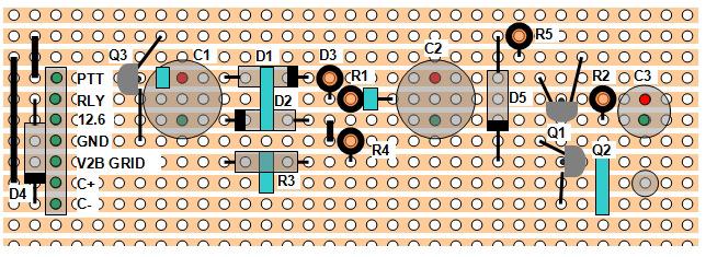
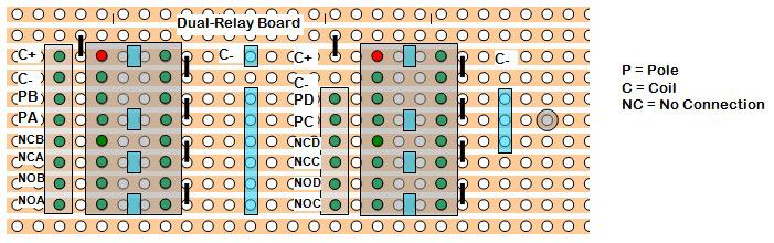
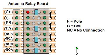
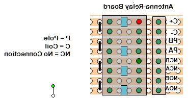
1 HW-101 QSK Modification T/R Relay Replacement The HW and SB series of transceivers have two 4PDT relays which provide T/R, In this modification, these two relays are replaced by three 2PDT relays. These are DS series relay, part number DS2E-S-DC24V. This document describes how the conversion to faster relays was performed by N4YG. It is intended only as a guide because it is one of many ways that it could have been done. Other than removal of the connections to the original relays and addition of a resistor, nothing is changed or removed from the HW-101. My relays were good, so I left them mounted in the chassis. Three small boards were constructed using Veroboard. These are shown in the block diagram below. The Transmit Relay Board contains only and single DS relay, whereas the Dual-Relay Board contains two. The Relay Driver Board contains the power supply and the control circuitry. The latter 2 boards were located near RL2 and were strapped to the existing cable harness. The small Transmit Relay Board was located near RL VAC PTT V12B Cathode V12B Grid Relay Driver Board C+ C- Amp Relay Transmit Relay Board Dual-Relay Board P (2) NC (2) NO (2) P (4) NC (4) NO (4) RL1 Previous Connections RL2 Previous Connections
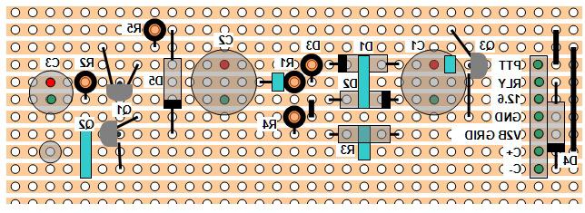
2 Relay Driver Board All inputs come from V12, which fortunately is located very near RL VAC from pin 5, Push-To-Talk (PTT) from pin 8 and audio (VOX) from pin 9. Filament voltage is applied to a double and then to a circuit somewhat like a regulator which drops the voltage to 24 to 26 VDC. FET Q2 drives the coils of the relays which, unlike ordinary relays, are polarized. Q2 is turned on by either the PTT or VOX signal. The PTT voltage is a +15 volt cathode bias which is shorted to ground by the mic button during transmit. The VOX signal contains either transmit audio or the CW sidetone taken from the grid of the relay driver tube V12B. When Q2 turns on, not only are the three DS relays are activated, but the output labeled Amp Relay is grounded. This will activated any modern linear amplifier if it is connected. The voltage at this terminal should not exceed 24 volts, which means an unmodified SB-220 cannot be connected here. My SB-220 has a mod in it which allows me to connect it here. This mod is like one commonly referred to as SoftKey. An unmodified older amplifier has higher voltage at its relay terminal, which requires a relay in the controlling transmitter or transceiver. We have chosen the parallel the two switches in the relay on the Transmit Relay Board. In not paralleled, one could be used for linear amp activation as in the original configuration. Getting It Done Again, this is the way I did it. This will describe the procedure, but you may want to use this as a guide to doing it another way. The last page of this document is group of images of the 3 boards. Begin by printing this page, making sure that it is printed at 100% scale. Cut Veroboard to the size shown. Count the holes. Then, referring to the reverse image, mark the places where the copper strips are to be broken. Remove the copper. Mark the board so that you will know which edge is the top. Cut out the overlay image, making them larger than the board. Hold the board up to light and place the overlays on top of the board and make sure you can align the components with the holes in the board. Apply glue (I use a glue stick) to the paper overlays and

3 glue them to the top of the board. With an awl or ice pick, punch holes where the components go through the boards. Now place the components of the board and carefully solder them in place. Attach wires of sufficient length to the board. Inspect the finished boards to make sure there are no solder bridges. Now that you have the boards completed, you are almost ready to install them in the transceiver. First, it is a good idea to make sure that the power supply on the Relay Driver Board operates properly. Connect wires from 12.6 and GND on the board to pin 5 and the center pin respectively of V12. Being careful not to short anything, turn on the transceiver and check the voltage at C+. It should be between 24 and 27 volts. If all is well proceed. Place the Transmit Relay Board near RL1 and the Dual-Relay Board and the Relay Driver Board near RL1. Refer to the graphic of the old relay pins and also remember that tube pins are numbered in clockwise direction when viewed from the bottom of the board. I recommend that connections to RL1 be removed oneby-one. Connect the wires from the Transmit Relay Board after disconnecting them from RL1 as follows: - C+ and C- to the corresponding points on the Relay Driver Board - P to the ANTENNA jack (pin 1 of RL1) - NO to the transmitter output (pin 5 of RL1) - NC to the receiver input (pin 9 of RL1) Disconnect the GREEN wire attached to pin 14 of RL1. This will disable both RL1 and RL2.
4 Connect wires from the Relay Driver Board to the adjacent PC board which contains V12 as follows: - C+ and C- to the corresponding points on the Dual-Relay Board to pin 5 of V12 - GND to the center pin of V12 - PTT to pin 8 of V12 - V12B Grid to pin 9 of V12 - RLY to the Amplifier Relay line (only if softkey installed in old amp) Connect wires coming from Dual-Relay Board to wires removed from RL2 as follows: Normally Closed Contacts - NCA 1 - White-Red - NCB 2 White-Yellow-Yellow (2 wires) - NCC 3 White-Red-Red )2 wires) - NCD 4 White-Blue (2 wires) Normally Open Contacts - NOA 5 - Yellow - NOB 6 - Blue (2 wires) - NOC 7 White-Orange-Orange - NOD 8 White=Violet-Violet (2 wires) Poles - PA 9 White-Blue-Blue - PB 10 - Ground - PC 11 White-Orange - PD 12 White-Green One final thing and you are done. Connect a 470K resistor across R903, that is, in parallel with it. It is a 2.3 M resistor connected to the VOX DELAY pot located on the rail along the side of the chassis. The thresholds are a bit different in the new system and this allows shorter delays in the VOX circuit. Test it. It should be good to go, and nice.
5

6
Microsystems. SCI-6 Sound Card Interface Kit Version 1.09 January 2015
 UM Unified Microsystems SCI-6 Sound Card Interface Kit Version 1.09 January 2015 The SCI-6 interface was designed to be a low cost, high quality interface between your PC s sound card and radio transceiver.
Universal Keying Adapter 3+
 Universal Keying Adapter 3+ The Universal Keying Adapter Version 3+ kit will allow you to key nearly any transmitter or transceiver with a straight key, electronic keyer, computer serial or parallel port
BehringerMods.com. Instructions for modification of Behringer SRC analog inputs and outputs
 BehringerMods.com Instructions for modification of Behringer SRC analog inputs and outputs The following instructions will cover the details of fully modifying a unit with analog output and analog input
USER MANUAL FOR HARDWARE REV
 PI-REPEATER-2X 1. WELCOME 2. CONTENTS PAGE 1 3. GETTING STARTED There are many features built into this little board that you should be aware of as they can easily be missed when setting up the hardware
Connecting LEDs to the ADB I/O
 Application Note AN-2 By Magnus Pettersson September 26 1996 Connecting LEDs to the I/O Introduction The following notes are for those of you who are a bit inexperienced with hardware components. This
Installation/assembly manual for DCC/Power shield
 Installation/assembly manual for DCC/Power shield The DCC circuit consists of the following components: R1/R6 R2/R3 R4/R5 D1 C2 2 kω resistor ½ Watt (colour code Red/Black/Black/Brown/Brown) 10 kω resistor
Cumbria Designs T-1. C-1 Controller. User Manual
 Cumbria Designs T-1 C-1 Controller User Manual CONTENTS 1 INTRODUCTION 2 2 CIRCUIT DESCRIPTION 2 3 ASSEMBLY 3 4 CONNECTIONS AND CONFIGURATION 4 5 TESTING 6 Appendix A C-1 Circuit Diagram and PCB Component
ST-400 / ST-600 STEREOCOM Installation Instructions
 ST-400 / ST-600 STEREOCOM Installation Instructions INTRODUCTION ATTENTION INSTALLER: To assure a trouble free installation, please read the entire instructions through once before beginning. CONFIGURATION
PN PSTK-120 PowerSwitch Tail 120vac Kit PN PSTK-240 PowerSwitch Tail 240vac Kit
 CAUTION: Please make sure you have or have access to the skills necessary to assemble and use this product. Always secure the case with the included screws before applying electrical power to the power
QRPometer Assembly Manual Copyright 2012 David Cripe NM0S The 4 State QRP Group. Introduction
 QRPometer Assembly Manual Copyright 2012 David Cripe NM0S The 4 State QRP Group Introduction Thank you for purchasing a QRPometer. We hope you will enjoy building it and and find it a useful addition to
Arrakis Systems 6604 Powell Street / Loveland, Colorado 80538
 Arrakis Systems 6604 Powell Street / Loveland, Colorado 80538 Input and Output wiring for the 150sc, 500sc, 2000sc and 2100sc audio consoles. A Input Channel Wiring (Back of Console) 6. Left Input 5. Left
MP54 SOUND for AC track power by
 ACv0 MP54 SOUND for AC track power by CAUTION: THIS DEVICE CAN BE DAMAGED BY STATIC DISCHARGE. PLEASE EXERCISE CARE DURING INSTALLATION TO AVOID THIS POSSIBILITY. DISCHARGE YOURSELF TO AN ELECTRICAL GROUND
Sierra Radio Systems. Making a Keyer with the. HamStack. Project Platform
 Sierra Radio Systems Making a Keyer with the HamStack Project Platform Introduction The HamStack Project Board includes primary interface elements needed to make a high quality CW keyer. Using the LCD
Figure 1. 6-Way JAMMA Switcher
 RiddledTV.com 6-Way, Single-Board JAMMA Switcher INSTALLATION GUIDE Figure 1. 6-Way JAMMA Switcher Features: Supports 6 JAMMA boards Only 1 JAMMA board is powered at a time. No external remotes required
MAIN PCB (The small one)
") THANKS FOR CHOOSING ONE OF OUR KITS! This manual has been written taking into account the common issues that we often find people experience in our workshops. The order in which the components are placed
THANKS FOR CHOOSING ONE OF OUR KITS! This manual has been written taking into account the common issues that we often find people experience in our workshops. The order in which the components are placed
Insert the male, 90 angled, 2x10 connectors into the corresponding 2x10 sockets and put them in place, flat under the PCB. Solder.
 MC624 Assembly guide Safety warning The kits are main powered and use potentially lethal voltages. Under no circumstance should someone undertake the realisation of a kit unless he has full knowledge about
Track Power Control. General:
 Track Power Control General: Track power is supplied by the transformers thru the TIUs mounted on five wiring panels located along the aisles and suspended from the layout facia. The power is then routed
High Power (15W + 15W) Stereo Amplifier
 Stereo Amplifier") High Power (15W + 15W) Stereo Amplifier Build Instructions Issue 1.0 Build Instructions Before you put any components in the board or pick up the soldering iron, just take a look at the Printed Circuit
High Power (15W + 15W) Stereo Amplifier Build Instructions Issue 1.0 Build Instructions Before you put any components in the board or pick up the soldering iron, just take a look at the Printed Circuit
Seeburg JCU-DEC Kit Convert Your Seeburg DEC Wallbox Into a Jukebox
 Seeburg JCU-DEC Kit Convert Your Seeburg DEC Wallbox Into a Jukebox MP3 Compact Flash Player Coin Operated or Free Play Integrated Power Amplifier Line-Out to External Amplifier Programmable Autoplay IR
Research Concepts RC2500 Antenna Interface Unit (AIU) Board Set
 Board Set") Research Concepts RC2500 Antenna Interface Unit (AIU) Board Set A board set has been developed that can be incorporated into an AIU for an RC2500 antenna controller. This board set is the basis of RC2500
Research Concepts RC2500 Antenna Interface Unit (AIU) Board Set A board set has been developed that can be incorporated into an AIU for an RC2500 antenna controller. This board set is the basis of RC2500
Single cable kit for the FCB1010
 Single cable kit for the FCB1010 1. What is it? With this kit, you can turn your FCB1010 into a phantom powered floorboard, which can do 2-way MIDI communication over one single cable. After installing
2010, 2013 Azatrax.com MRD2-S USB with Switch Control installation instructions pg. 1 of 6
 Installation Instructions Azatrax Dual Infrared Model Train Detector MRD2-S, USB with Switch Control What it is: The MRD2-S is a two-channel model train detector. It can detect model trains at two different
Touch Sense Controller
 Touch Sense Controller Paul Boston May 11, 2011 (Modified May 22, 2014) (Modified Dec 28, 2015) The Touch Sense Controller is a microprocessor-controlled circuit designed to provide a switch closure when
1/Build a Mintronics: MintDuino
 1/Build a Mintronics: The is perfect for anyone interested in learning (or teaching) the fundamentals of how micro controllers work. It will have you building your own micro controller from scratch on
BLU- CIF Interface Board
 BLU- CIF Interface Board The BLU-CIF Interface Board simplifies the wiring of all of the BLU products to the BSS Audio London Series Digital Signal Processors. It allows for Cat5e wiring termination, as
Instruction Manual for BE-SP3 Circuit. 10/21/07
 Page 1 of 54 Instruction Manual for BE-SP3 Circuit. 10/21/07 Page 1 Index: Page 2 BE-SP3 Circuit Specifications. Page 3-4 Intro to the BE-SP3. Page 5 Basics of serial to parallel. Page 6-7 ASCII Code.
INSTALLATION INSTRUCTIONS
 INSTALLATION INSTRUCTIONS MicroComm DXI MAI-425 Master Audio Interface. Intent & Scope This document describes the installation procedure for the MAI-425 Master Audio Interface. The earliest version of
Assembly Instructions (8/14/2014) Your kit should contain the following items. If you find a part missing, please contact NeoLoch for a replacement.
 Your kit should contain the following items. If you find a part missing, please contact NeoLoch for a replacement.") NeoLoch NLT-28P-LCD-5S Assembly Instructions (8/14/2014) Your kit should contain the following items. If you find a part missing, please contact NeoLoch for a replacement. Kit contents: 1 Printed circuit
NeoLoch NLT-28P-LCD-5S Assembly Instructions (8/14/2014) Your kit should contain the following items. If you find a part missing, please contact NeoLoch for a replacement. Kit contents: 1 Printed circuit
Connecting the THP-700RTS to a Telephone and Radio Console - Summary. DynaMetric. Made in USA THP-700RTS
 Connecting the to a Telephone and Radio Console - Summary RECORDER 700RTS 700RTS PHONE PIN HEADSET PIN JACK PIN PLUG* PIN JACK 1 1 MIC 1 1 Make same 2 2 EAR 2 2 as Phone 3 3 EAR 3 3 Jack 4 4 MIC 4 4 PIN
General-Purpose Microcontroller Module 12a Hardware Reference Release 1.4a (October 11, 2017)
") General-Purpose Microcontroller Module 12a Hardware Reference 1 General-Purpose Microcontroller Module 12a Hardware Reference Release 1.4a (October 11, 2017) Purpose: General-purpose platform to accommodate
General-Purpose Microcontroller Module 12a Hardware Reference 1 General-Purpose Microcontroller Module 12a Hardware Reference Release 1.4a (October 11, 2017) Purpose: General-purpose platform to accommodate
Megatouch FORCE Monitor Chassis Board Replacement
 Megatouch FORCE Monitor Chassis Board Replacement Visit the Merit Industries, Inc. Web site http://www.meritind.com merit industries, inc. PM0337-01 Rev C Table of Contents FORCE Classic Monitor Chassis
Button Code Kit. Assembly Instructions and User Guide. Single Button Code Entry System
 Button Code Kit Single Button Code Entry System Assembly Instructions and User Guide Rev 1.0 December 2009 www.alan-parekh.com Copyright 2009 Alan Electronic Projects Inc. 1. Introduction... 4 1.1 Concept
K8+ Single Chip Keyer Manual August 13, 1998 Steven T. Elliott - K1EL
 Introduction K8+ Single Chip Keyer Manual August 13, 1998 Steven T. Elliott - K1EL This manual will describe the operation of the K8+ Keyer which is a low cost automatic Morse keyer designed by Steve,
KDR00301 DMX Controlled Relay Kit
 KDR00301 DMX Controlled Relay Kit This is a DMX512-A relay kit using ANSI approved RJ-45 connectors for DMX networks. Power requirements are 12 Vdc @ 200 ma. The relay contact rating is 10 Amp @ 120 or
BuffaloLabs WiFi Lantern Assembly guide version 1
 BuffaloLabs WiFi Lantern Assembly guide version 1 Needed equipment: Solder iron Solder wire Cutter Wire stripper (optional) Hot glue gun Overview of the components (not including USB cable and box panels)
QRPGuys Digital Dial/Frequency Counter
 QRPGuys Digital Dial/Frequency Counter First, familiarize yourself with the parts and check for all the components. If a part is missing, please contact us and we will send one. You must use qrpguys.parts@gmail.com
e-ask electronic Access Security Keyless-entry OEM / Dealer / Installer Cargo Lock / Unlock Version Installation & Instructions (UM04 ~ )
") e-ask electronic Access Security Keyless-entry OEM / Dealer / Installer Cargo Lock / Unlock Version Installation & Instructions (UM04 ~ 18990-04) Table of Contents Introduction... 1 e-fob Operation and
e-ask electronic Access Security Keyless-entry OEM / Dealer / Installer Cargo Lock / Unlock Version Installation & Instructions (UM04 ~ 18990-04) Table of Contents Introduction... 1 e-fob Operation and
Secured Series: Hub Plus Kit Single Door Controller Package Installation Manual
 Secured Series: Hub Plus Kit Single Door Controller Package Installation Manual This package is designed to simplify the connections to our Secured Series Hub Plus Controller. This will translate into
SPIRIT. Phase 5 Analog Board Computer and Electronics Engineering
 SPIRIT Phase 5 Analog Board Computer and Electronics Engineering In this exercise you will assemble the analog controller board and interface it to your TekBot. Print out the schematic, silkscreen and
BLU- CIF Interface Board
 BLU- CIF Interface Board The BLU-CIF Interface Board simplifies the wiring of all of the BLU products to the BSS Audio London Series Digital Signal Processors. It allows for Cat5e wiring termination, as
Using solderless breadboards
 Page 1 of 9 Using solderless breadboards This document describes how to use the solderless breadboards available in the experimental didactic lab (LED, previously LADISPE) of Politecnico di Torino. 1 Setting
UCBB dual port breakout board user's manual
 UCBB dual port breakout board user's manual 1/14 Contents 1 Features 2 Dimensions 3 Connectors 3.1 Screw terminals 3.2 IDC ports 3.3 Powering 3.4 Outputs 3.5 Inputs 4 LED indicators 5 Example connections
INSTRUCTION MANUAL MODEL 8515D DEMAGNETIZER
 INSTRUCTION MANUAL MODEL 8515D DEMAGNETIZER REV.1 BEGINNING WITH SERIAL # 37199 Created 12-02-2005 IMPORTANT THE FIXTURE MUST BE CONNECTED BEFORE TURNING ON THE DEMAGNETIZER. THE DEMAGNETIZER WILL NOT
SERGE Dual Extended ADSR 2017
 SERGE Dual Extended ADSR 2017 The Serge Dual Extended ADSR module contains 2 identical Extended ADSR sections, each consisting of a main pcb and a panel pcb: Please note: Orientation of the main pcb: power
Hardware Manual 1240i-485
 Hardware Manual -485 Intelligent Step Motor Driver with Multi-drop RS-485 Interface 920-0033 A 7/6/2010 motors drives controls -2- Table of Contents Introduction...4 Features...4 Block Diagram...4 Getting
BATC Kit MTK2 for MiniTiouner
 BATC Kit MTK2 for MiniTiouner Serit FTS4335V NIM Converter Document Change Log 2017-02-22 v1.01 First release 2017-03-01 v1.04 Minor mods Serit FTS4335V, Converter and MiniTiouner (built by G4KLB) Serit
BLU- CIF2 Interface Board
 BLU- CIF2 Interface Board The BLU-CIF2 Interface Board simplifies the wiring of all of the BLU products to two BSS Audio London Series Digital Signal Processors. It allows for Cat5e wiring termination,
Arduino Panel Meter Clock. By Russ Hughes
 Arduino Panel Meter Clock By Russ Hughes (russ@owt.com) OVERVIEW My father has been a lifelong Ham Radio Operator with a fondness for almost anything with a panel meter. After seeing the Trinket Powered
MartMod Mk5. Thank you for choosing what we believe is the best voice modulator and dalek electronics system that you can buy.
 MartMod Mk5 Thank you for choosing what we believe is the best voice modulator and dalek electronics system that you can buy. For clarification, the MartMod that was produced by Vince (with Martin's help),
INSTALLATION INSTRUCTIONS
 CONSOLE CONNECTOR KIT 7830 FOR USE WITH: LESLIE Speaker Model 130 Various single and double channel organs INSTALLATION INSTRUCTIONS KIT CONTENT Console Connector 137283 Switch Assembly, Cable Assembly,
T1203 DME, ATC, LRA DISCRETE FUNCTION INTERFACE UNIT
 OPERATION MANUAL T1203 DME, ATC, LRA DISCRETE FUNCTION INTERFACE UNIT MANUAL NUMBER: 06-1203-01 (Hard Copy) E6-1203-01 (CD) REVISION: 0 DATE: 03/26/2007 WARNING: INFORMATION SUBJECT TO EXPORT CONTROL LAWS
HARDWARE OPERATIONS MANUAL
 HARDWARE OPERATIONS MANUAL Table of Contents INTRODUCTION... 2 SECTION 1: HARDWARE COMPONENT ASSEMBLIES... 2 MECHANICAL HARDWARE AND CASE... 2 PCB ASSEMBLY... 4 ISD RECORDING CIRCUIT... 5 BREADBOARD ASSEMBLY...
INSTALLATION INSTRUCTIONS. DCC and DCE Installation Instructions. Table of Contents
 INSTALLATION INSTRUCTIONS MicroComm DXL DCC and DCE Installation Instructions Table of Contents 1. Intent & Scope 1 2. Description 1 3. DCC Backup Battery 2 4. Field Connections to the DCC 4 5. Field Connections
Advanced Strobe 1.0 Kit
 Kit Instruction Manual Eastern Voltage Research, LLC December 2013, Rev 1 1 http://www.easternvoltageresearch.com Kit Introduction to the Kit Thank you for purchasing the Kit. If you are looking for a
Onwards and Upwards, Your near space guide. Figure 1. CheapBot Line Follower
 The CheapBot Line Follower is a plug-in single-board sensor for almost any programmable robot brain. With it, a robot can detect the presence of a black or white zone beneath its two sensors. In its simplest
Pacific Antenna Easy TR Switch Kit
 Pacific Antenna Easy TR Switch Kit Kit Description The Easy TR Switch is an RF sensing circuit with a double pole double throw relay that can be used to automatically switch an antenna between a separate
Table of Contents 1 ABOUT THIS GUIDE CONTACT INFORMATION ANTENNA INSTALLATION... 4
 Table of Contents 1 ABOUT THIS GUIDE... 3 1.1 CONTACT INFORMATION... 3 2 ANTENNA INSTALLATION... 4 2.1 GENERAL INFORMATION... 4 2.2 SPECIFIC MOUNTING EXAMPLES... 5 2.3 CONNECTOR MOISTURE PROTECTION...
These are the illustrated step-by-step guidelines for upgrading your Quad 306 with the Dada Electronics upgrade-kit.
 Quad 306 DIY illustrated guidelines version 1.1 These are the illustrated step-by-step guidelines for upgrading your Quad 306 with the Dada Electronics upgrade-kit. We will replace all electrolytic capacitors,
BLU- CIF2 Interface Board
 BLU- CIF2 Interface Board The BLU-CIF2 Interface Board simplifies the wiring of all of the BLU products to two BSS Audio London Series Digital Signal Processors. It allows for Cat5e wiring termination,
Alesis MMT8 16x Memory Expansion Modification (all grey model MMT8 s)
") Alesis MMT8 16x Memory Expansion Modification (all grey model MMT8 s) by Graham Meredith, 2006 Revised 13 th January 2009 gmeredith1@yahoo.com.au This modification expands the memory of the Alesis MMT8
Alesis MMT8 16x Memory Expansion Modification (all grey model MMT8 s) by Graham Meredith, 2006 Revised 13 th January 2009 gmeredith1@yahoo.com.au This modification expands the memory of the Alesis MMT8
1. Mount the echo and tremolo control switches under the keyboard shelf, in a position convenient for the organist.
 CONSOLE CONNECTOR KIT 8101 INSTALLATION INSTRUCTIONS FOR USE WITH: HAMMOND Organ Models A-100, D-100, RT2, RT3 LESLIE Speaker Models 122, 122RV KIT CONTENT Console Connector Assembly 047357 Echo Control
HS-27-Mini. Headstage preamplifier providing 27 channels of unity gain amplification.
 HS-27-Mini Headstage preamplifier providing 27 channels of unity gain amplification. 9/16/2013 Neuralynx, Inc. 105 Commercial Drive, Bozeman, MT 59715 Phone 406.585.4542 Fax 866.585.1743 www.neuralynx.com
LushOne Inca Synth Module Build Instructions
 LushOne Inca Synth Module Build Instructions Getting started If you can build the LushOne base module then then building the Inca should be easy Remember: Accuracy and neatness is more important than speed
Voice Keyer Kit by DH8BQA (BX-184)
") Voice Keyer Kit by DH8BQA (BX-184) 2011 5 24 1 Quick assembly guide Most amateur radios do not have an internal voice memory for transmitting. If you want to use such a convenient feature you can build
Voice Keyer Kit by DH8BQA (BX-184) 2011 5 24 1 Quick assembly guide Most amateur radios do not have an internal voice memory for transmitting. If you want to use such a convenient feature you can build
DEV-1 HamStack Development Board
 Sierra Radio Systems DEV-1 HamStack Development Board Reference Manual Version 1.0 Contents Introduction Hardware Compiler overview Program structure Code examples Sample projects For more information,
Specialists in SOUND Management 178 East Arrow Highway, San Dimas, CA (909) Sigtronics UltraSound CFR Emergency Intercom System
 Sigtronics UltraSound CFR Emergency Intercom System") Sigtronics UltraSound CFR Emergency Intercom System INSTALLATION AND OPERATING INSTRUCTIONS INTRODUCTION ATTENTION INSTALLER: To assure a trouble free installation, please read these entire instructions
Sigtronics UltraSound CFR Emergency Intercom System INSTALLATION AND OPERATING INSTRUCTIONS INTRODUCTION ATTENTION INSTALLER: To assure a trouble free installation, please read these entire instructions
VS. 4 Game Selector INSTALL GUIDE
 VS. 4 Game Selector INSTALL GUIDE Each DK Selector includes the following items: 1. VS. 4 Game Selector PWB 2. 4 power cables 12, 14, 16 & 18 3. Ribbon daisy chain cable 4. Mounting feet and screws Some
ARES 2 Tone Sequential Tone Decoder Kit Assembly Instructions
 Tools Required: ARES Tone Sequential Tone Decoder Kit Assembly nstructions 3/8 Electric Drill Soldering ron Wire Strippers Needle Nose Pliers Wire Cutters Ruler 60/40 Solder Phillips Screw Driver /8, 5/64,
KDR00101 DMX Controlled Relay Kit
 KDR00101 DMX Controlled Relay Kit This is a DMX512-A relay kit using ANSI approved RJ-45 connectors for DMX networks. Power requirements are 12 Vdc @ 100 ma. The relay contact rating is 10 Amp @ 120 or
HS-27 Manual 5/2/2013. Neuralynx, Inc. 105 Commercial Drive, Bozeman, MT Phone Fax
 5/2/2013 Neuralynx, Inc. 105 Commercial Drive, Bozeman, MT 59715 Phone 406.585.4542 Fax 866.585.1743 www.neuralynx.com support@neuralynx.com Table of Contents 1 Headstage 27 Overview... 3 2 Glossary...
Soartronic IOIO UART interface v2e assembly manual.
 Soartronic IOIO UART interface v2e assembly manual www.soartronic.com 1 This manual is for both IOIO v1 and IOIO-OTG Components assembled should look like this: components marked with RED arrows have polarity,
DELUXE STEREO AMPLIFIER KIT
 ESSENTIAL INFORMATION BUILD INSTRUCTIONS CHECKING YOUR PCB & FAULT-FINDING MECHANICAL DETAILS HOW THE KIT WORKS CREATE YOUR OWN SPEAKER DOCK WITH THIS DELUXE STEREO AMPLIFIER KIT Version 2.0 Build Instructions
UDPSDR-TX2 Transmitter
 UDPSDR-TX2 Transmitter User s Manual Version 1.1 7 August 2014 Copyright 2014 Zephyr Engineering, Inc 1 HARDWARE DESCRIPTION 2 1.1 UDPSDR-TX2 Connectors, Headers and Jumpers 2 1.1.1 UDPSDR-TX2 Connectors
the TS-520 Noise Blanker board to and making wiring changes to your SB-303 receiver!!!!
 The Kenwood TS-520 s Noise Blanker board, ID# X54-1080-10, can be installed in a Heathkit SB-303 receiver quite easily. The Noise Blanker board operates directly off of the SB-303 s 15VDC supply. Therefore,
INSTALLATION INSTRUCTIONS. FST-420 Fiber Station Transceiver
 INSTALLATION INSTRUCTIONS MicroComm DXI Fiber Station Transceiver. Intent & Scope This document describes the installation procedure for the Fiber Station Transceivers. 2. Description The Fiber Station
Alesis MMT8 16x Memory Expansion Modification (Black model MMT8 s) Equipment. Components required. Other bits:
 Equipment. Components required. Other bits:") Alesis MMT8 16x Memory Expansion Modification (Black model MMT8 s) by Graham Meredith, 006 Revised 15 th January 009 gmeredith1@yahoo.com.au This modification expands the memory of the Alesis MMT8 to 16x
Alesis MMT8 16x Memory Expansion Modification (Black model MMT8 s) by Graham Meredith, 006 Revised 15 th January 009 gmeredith1@yahoo.com.au This modification expands the memory of the Alesis MMT8 to 16x
CO-485USB USB to RS-485 CONVERTER TECHNICAL REFERENCE
 TABLE OF CONTENTS CO-485USB USB to CONVERTER TECHNICAL REFERENCE Specifications, Description and Technical Support... page 1 Connection Diagram... page 2 Set-Up & Testing... page 3 & 4 Power Supply Shunts...
PICAXE EXPERIMENTER BOARD (AXE090)
") (AXE00) Description: The PICAXE experimenter board allows circuits for any size/revision of PICAXE chip ( / / ) to be quickly tested using a prototyping breadboard. The experimenter board provides power
(AXE00) Description: The PICAXE experimenter board allows circuits for any size/revision of PICAXE chip ( / / ) to be quickly tested using a prototyping breadboard. The experimenter board provides power
XYLOPHONE KIT ESSENTIAL INFORMATION. Version 2.0 CREATE YOUR OWN ELECTRONIC MUSICAL INTRUMENT WITH THIS
 ESSENTIAL INFORMATION BUILD INSTRUCTIONS CHECKING YOUR PCB & FAULT-FINDING MECHANICAL DETAILS HOW THE KIT WORKS CREATE YOUR OWN ELECTRONIC MUSICAL INTRUMENT WITH THIS XYLOPHONE KIT Version 2.0 Build Instructions
The SilverNugget is a servo controller/driver for NEMA 17 & 23 frame microstep motors.
 Date: 5 November 2008 www.quicksilvercontrols.com SilverNugget N2 M-Grade The SilverNugget is a servo controller/driver for NEMA 17 & 23 frame microstep motors. Property of Page 1 of 13 This document is
RC-210 Repeater Controller Assembly Manual
 Arcom Communications 24035 NE Butteville Rd Aurora, Oregon 97002 (503) 678-6182 arcom@ah6le.net RC-210 Repeater Controller Assembly Manual Hardware Version 3.0 Original Release Date September 13, 2004
Ultimate LPF kit: Relay-switched LPF kit
 Ultimate LPF kit: Relay-switched LPF kit PCB Revision 4 1. Introduction Thank you for purchasing the QRP Labs relay-switched low-pass filter (LPF) kit. This kit is designed to complement the Ultimate3
DENTRON CLIPPERTON-L POWER SUPPLY MODULE v5.3 ASSEMBLY & INSTALLATION INSTRUCTIONS
 DENTRON CLIPPERTON-L POWER SUPPLY MODULE v5.3 ASSEMBLY & INSTALLATION INSTRUCTIONS WARNING: This upgrade is not for the faint of heart or inexperienced in amplifier theory and repairs as the voltages inside
TLE9869 Eval.Kit V1.0 Users Manual
 TLE9869 Eval.Kit V1.0 Users Manual Contents Abbreviations... 2 1 Concept... 3 2 Interconnects... 4 3 Test Points... 5 4 Jumper Settings... 6 5 Communication Interfaces... 7 5.1 LIN (via Banana jack and
Series 3700 Screw Terminal Assemblies Installation Instructions
 Keithley Instruments, Inc. 28775 Aurora Road Cleveland, Ohio 44139 1-888-KEITHLEY www.keithley.com Series 3700 Screw Terminal Assemblies Installation Instructions Introduction This document contains handling
INSTALLATION INSTRUCTIONS
 INSTALLATION INSTRUCTIONS MicroComm DXI. Intent & Scope This document describes the installation procedure for the IMS-30 Intercom Master Station and the MAI-420 or MAI-20 Master Audio Interface. The earliest
VIM Mercedes Benz Sprinter Contact Intermotive for additional applications
 An ISO 9001:2008 Registered Company VIM910 2017 Mercedes Benz Sprinter Contact Intermotive for additional applications Introduction The VIM will allow the OEM steering wheel switches to control aftermarket
Sierra Radio Systems. HamStack. Project Board Reference Manual V1.0
 Sierra Radio Systems HamStack Project Board Reference Manual V1.0 Welcome HamStack Project Board Reference Manual Revision 1.0.3 2011 George Zafiropoulos, KJ6VU and John Best, KJ6K This guide provides
PCB-AVR1284-3U. AVR Microcontroller Development PCB for Atmel 40-pin DIP AVRs.
 PCB-AVR1284-3U AVR Microcontroller Development PCB for Atmel 40-pin DIP AVRs. Part Number: PCB-AVR1284-3U (unpopulated PCB, no parts) Features A development board for Atmel 40 pin AVR microcontrollers.
Manual Version March 2007
 Manual Version 1.1 - March 2007 Page 1 Table of Contents Section1: 6922 Line Board Build... 3 6922 Line Board Version Notes... 5 6922 Line Board Build - HARD-WIRED VERSION... 5 Final Connections and Checks
MODEL NC105 DIGITAL CODED SQUELCH ENCODER/DECODER INSTRUCTION MANUAL
 15385 Carrie Drive Grass Valley, CA 95959 Office: (530) 477-8400 Tech. Support: (530) 477-8402 FAX: (530) 477-8403 Sales: (800) 874-8663 Email: tech@norcommcorp.com Web: www.norcommcorp.com MODEL NC105
6222 Two Door Module Technical Operations Manual
 6222 Two Door Module Technical Operations Manual TABLE OF CONTENTS Specifications...3 Overview...4 Operations...5 Custom Access Mode...5 Standard Access Mode...5 Offline Access Mode...5 Offline Memory...5
RC210 Repeater Controller Assembly Manual
 Arcom Communications 24035 NE Butteville Rd Aurora, Oregon 97002 (503) 678-6182 arcom@ah6le.net http://www.arcomcontrollers.com/ RC210 Repeater Controller Assembly Manual Hardware Version 3.3 Reproduction
SRI-02 Speech Recognition Interface
 SRI-02 Speech Recognition Interface Data & Construction Booklet The Speech Recognition Interface SRI-02 allows one to use the SR-07 Speech Recognition Circuit to create speech controlled electrical devices.
January Bob Wright. 1 P age Bob Wright
 The upgrade is completed using the 401 control board and three Step1 driver boards supplied as a kit by Conqueror Design and Engineering Ltd. The kit includes all cable terminators for connections to the
INSTALLATION/OPERATION INSTRUCTIONS U3800 MASTER STATION
 360 Franklin Street, Box 15054, Worcester, MA 01615-0054 TEL. 508-751-5800 FAX 508-753-5827 DESCRIPTION INSTALLATION/OPERATION INSTRUCTIONS U3800 MASTER STATION The U3800 Master Station is the heart of
Voice Evacuation Control Panel Main Circuit Board Replacement Product Installation Document
 Voice Evacuation Control Panel Main Circuit Board Replacement Product Installation Document Document 50795 Rev B 10/10/01 ECN 01-507 This Product Installation Document outlines the replacement of the Main
Dynalec MSIC (Monitor Speaker I/F Circuit) ( ) User s Manual
 ( ) User s Manual") Dynalec MSIC (Monitor Speaker I/F Circuit) (62325-225) User s Manual Rev 27FEB02 GENERAL This manual contains information concerning a description of operation for the Dynalec Monitor Speaker Interface
Dynalec MSIC (Monitor Speaker I/F Circuit) (62325-225) User s Manual Rev 27FEB02 GENERAL This manual contains information concerning a description of operation for the Dynalec Monitor Speaker Interface
Assembly Instructions for the KA Electronics Elliptic Equalizer
 Assembly Instructions for the KA Electronics Elliptic Equalizer Install IC sockets Elliptic Equalizer PC Board Stuffing Guide Place the PC Board on the work bench silkscreen side face up. Place twelve
PLMRMBT5B / PLMRMBT5S 600 Watt 2 Channel Bluetooth Enabled Marine Grade Amplifier
 PLMRMBT5B / PLMRMBT5S 600 Watt 2 Channel Bluetooth Enabled Marine Grade Amplifier PLMRMBT7B / PLMRMBT7S 1200 Watt 4 Channel Bluetooth Enabled Marine Grade Amplifier It s compact, waterproof design allows