Manual IOCard USB DimControl. Date:08/18/15 Rev.:1.1
|
|
|
- Betty Armstrong
- 5 years ago
- Views:
Transcription


1 Manual IOCard USB DimControl. Date:08/18/15 Rev.:1.1
2 Index: MANUAL IOCARD USB DIMCONTROL... 1 INDEX:... 2 INTRODUCTION:... 3 USB DIMCONTROL:... 3 ESCHEMA:... 3 CONNECTOR DESCRIPTION:... 4 Connector J7 to pedestal:... 4 OPERATION OF THE CARD:... 5 USB MODE FOR INDEPENDENT SOFTWARE USB MODE WITH SIOC Definition of the card:... 7 Definition of the variables:... 7 NO USB OR STANDALONE MODE Potentiometer for each channel:... 8 Master potentiometer for three channels:... 9 CARD OPERATIONS:... 9 LINKS OF INTEREST:


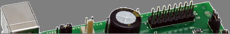
3 Introduction: IOCard USB DimControl Manual This board allows controlling the backlight brightness of the panels and / or modules using software and hardware depending on the computer or completely independently. It has 3 control modes: USB mode; with a master potentiometer for all channels and by individual potentiometers for each channel. Usb DimControl: This board controls 3-channel supply with 4 outputs for each channel using PWM control. The board supports up to 50 Volt power, each output supports up to 1 Amp with a limit of 2.5 Amps between all outputs. The card can be configured with dedicated software via USB and store in internal eprom memory the applicable maximum power for each channel and the power used by default when connecting. Variables can also be programmed using SIOC IOCP code. Using potentiometers, each channel can go from 0 to MAX linearly. The card mode 3 doesn't need to be connected to the USB port. Once configured, the plate can increase and decrease the brightness of the 3 channels at once, automatically managing the different intensities of each channel and being able to control different types of LEDs or bulbs. Schema: 3
. J7 = Specific connector for pedestal backlight.")
, range 0 to 255. SW1 = Jumper selector for feeding the card's electronics. USB = position 1, External power supply (5V) = position 3.")
4 Connector description: J1 = USB connector. J2 = Input power connector to supply the card's electronics (+5V in pin 1, pin 2 = GND), it is used when SW1 is on position 3. J6 = Input power connector to supply the outputs (0 to +50V, positive on pin 1, pin 2 = GND). J7 = Specific connector for pedestal backlight. J3/POT1 = Connector for potentiometer nº1, channel A (1), range 0 to 255. J4/POT2 = Connector for potentiometer nº2, channel B (2), range 0 to 255. J5/POT3 = Connector for potentiometer nº3, channel C (3), range 0 to 255. SW1 = Jumper selector for feeding the card's electronics. USB = position 1, External power supply (5V) = position 3. SW2 = Closed if we want the 5V card's electronics power to be the same for the outputs, then nothing is connected to J6 (we use the J2 power for the outputs). NO USB/USB = Jumper selector for USB mode (position 3) or standalone mode (position 1). NO POTS/POTS = Jumper selector for potentiometer mode (position 3) or not (position 1), its used in combination with the previous selector. NO/LINK POTS= Jumper selector for 3 potentiometer mode (position 1) or master potentiometer on POT1 (position 3). S1 a S4 = Connectors of channel A (1), pin1 positive/anothe and pin 2 negative/cathode). S5 a S8 = Connectors of channel B (2), pin1 positive/anothe and pin 2 negative/cathode). S9 a S12 = Connectors of channel C (3), pin1 positive/anothe and pin 2 negative/cathode). Connector J7 to pedestal: This connector is able to connect the USB DimControl (USB-Dimmer) to pedestal in order to control the backlight using the three channels available. The nomenclature of the outputs is as follows: VM: Common positive or common anode feed. O,1,1: (O)utput, (1) channel A, (1) output S1. O,1,2: (O)utput, (1) channel A, (2) output S2. O,1,3: (O)utput, (1) channel A, (3) output S3. O,1,4: (O)utput, (1) channel A, (4) output S4. O,2,1: (O)utput, (2) channel B, (1) output S5. O,2,2: (O)utput, (2) channel B, (2) output S6. O,2,3: (O)utput, (2) channel B, (3) output S7. 4
5 O,2,4: (O)utput, (2) channel B, (4) output S8. O,3,1: (O)utput, (3) channel C, (1) output S9. O,3,2: (O)utput, (3) channel C, (2) output S10. O,3,3: (O)utput, (3) channel C, (3) output S11. O,3,4: (O)utput, (3) channel C, (4) output S12. This connector can be used like the simple outputs "Sxx". Operation of the card: The board power (5V) can be done from the USB bus itself with SW1 at position 1 or external 5V supply connected to J2 with SW1 at position 3. If the lighting power exceeds 5V, SW2 is left open and the outputs are fed on J6 with up to 50V. If lighting power is 5V and it is wanted to use the same external source of card's electronics, we close SW2 and do not connect anything to J6. Importantly, the outputs will be different for each channel according to their limits, which will depend on the programming done in either USB modes available. The card has three operating modes, see each of them. USB mode for independent software. The USB DimControl card independent USB mode is able to control all parameters of the card via USB connection to your computer with a specific downloadable program (iocard_dimcontrol.exe) via Web on Opencockpits aid page and from the same download page of the product, without using SIOC. The jumpers settings for this mode are: NO USB: Position 3. NO POTS: Position 1. POTS LINK: Position 3. When the card is plugged into the computer it is immediately recognized by the control software iocard_dimcontrol.exe which reads the default values stored in the EPROM: 5

6 Once loaded the defaults, we can change the output value of each channel independently using sliders. We can also change the maximum power output of each channel and store it in the EPROM if you press the button UPDATE LIMITS. The range is 256 steps. These steps have zero to the maximum power of the card, i.e. if the maximum power of channel A is 40, the value of enlightenment never pass 40 although there remain more steps on the potentiometer or on the iocar_dimcontrol.exe software sliders. Establishing of limits is very important and can only be done from USB mode either independently or with SIOC (version 4.7B1 or higher). USB mode with Sioc. The dependent on SIOC USB mode is to control all parameters of the card using either IOCPConsole management or using a script. The version that recognizes the USB DimControl card is the up 4.7B1, downloadable from the Opencockpits aid web and from the same download page of the product. The jumpers settings for this mode are: NO USB: Position 3. NO POTS: Position 1. POTS LINK: Position 3. When the card is connected to the computer it is immediately recognized by SIOC: 6
7 In this mode we need a script to link the card to access the variables of channel management by IOCPconsole. Definition of the card: The USB DimControl card is recognized as USB-Dimmer by SIOC and to define it the type 17 Master definition is used: MASTER=XX,17,YY,ZZ XX indicates the index number (IDX) within our cards group. YY indicates the number of devices installed in our computer fixed to 1. ZZ indicates the number of the USB port to which it is connected (DEVICE). Example of 2 USB Dimmer cards installed in our computer: Master=0,17,1,70 Master=1,17,1,83 Definition of the variables: The card access is performed by IOCP variables defined as follows: Var VVVV, name NNNN, Link IOCARD_CONFIG, device DD, Output S VVVV = variable number. NNNN = variable name (optional). DD = index number defined on sioc.ini (if we have declared as 0: no need to put the reference to the number of Device). S = number of output. The variables which manage the card by IOCP are: Var 0001, Link IOCARD_CONFIG, Output 1 // =98 to can set the outputs values =99 to save the limits of each channel Var 0002, Link IOCARD_CONFIG, Output 2 // Maximum Value Channel A Var 0003, Link IOCARD_CONFIG, Output 3 // Maximum Value Channel B Var 0004, Link IOCARD_CONFIG, Output 4 // Maximum Value Channel C Var 0005, Link IOCARD_CONFIG, Output 5 // Intensity value (0-255) Channel A Var 0006, Link IOCARD_CONFIG, Output 6 // Intensity value (0-255) Channel B Var 0007, Link IOCARD_CONFIG, Output 7 // Intensity value (0-255) Channel C To assign values to outputs 2, 3, 4, 5, 6 and 7, output 1 (Output1) takes the value 98. To save the values entered in the outputs and limits, output 1 is assigned the value 99. Example of IOCP control: We keep the definition text as a script and load it, click on the button IOCPConsole and shows the following screen. 7


8 From this screen you can manage the maximum values of each channel and output values. We select the variable V0001 and give it value 98 to assign data to channels and limits, then we can select each output and assign the desired value and finally, to save the data, we send value 99 to V0001. With these two ways we can do three things, program the values with the independent software, another using a script to handle other definitions and leave the card in standalone mode. NO USB or standalone mode. USB DimControl iocard NO USB mode is able to control all parameters of the card using potentiometers without being connected to a computer, except the limits of each channel that need to be set up by one of the above two methods. The jumpers settings for this mode are: NO USB: Position 1. POTS NO: Position 3. POTS LINK: position 1 or 3. In this way we have two sub-modes, one with control values of each channel with its own potentiometer and another with a single potentiometer for all channels. Potentiometer for each channel: For each channel having its own output value management, POTS LINK selector must be in position 1 and a potentiometer connected to each channel connector (POT1, POT3 and POT2). 8
9 Master potentiometer for three channels: IOCard USB DimControl Manual This mode provides a change of output values with a single potentiometer for all channels. The POTS LINK selector must be in position 3 and the master potentiometer on the POT1 connector. In this way the full range of the master potentiometer will adapt to the useful zone set on each channel. Card operations: It should be noted some connotations of USB DimControl card If you connect a heavy load on the outputs may be a drop in the supply voltage, so that adequate feed must be taken into account. The card is suitable for connecting LEDs and bulbs in series and parallel with their respective resistors if needed. It is advisable to feed the outputs with the maximum withstand voltage for the LEDs and / or bulbs to have a good resolution in the range of control. Be very careful with the limits assigned to each channel and its outlets to avoid melting LED and/or bulbs. Remember that having the limits saved in the EPROM, the values will not rise beyond them though the potentiometer do all the way. This ends this manual, we invite you to read the manuals of the others Opencockpits elements and explore the SIOC software. We thank You for trusting us. Links of interest: Support zone for customers: 9
OPENCOCKPITS IOCard USBOUTPUTS INSTALLATION AND USER S MANUAL
 OPENCOCKPITS IOCard USBOUTPUTS INSTALLATION AND USER S MANUAL INTRODUCTION This card allows us to manage easily up to 64 outputs up to 40V and 500mA on each output, with a total amount of 2,5A. Also, the
Iocard USB DcMotors Manual. Date:15/02/12 Rev.:2.0
 Iocard USB DcMotors Manual Date:15/02/12 Rev.:2.0 Index: IOCARD USB DCMOTORS MANUAL... 1 INDEX:... 2 INTRODUCTION:... 3 USB DCMOTORS:... 3 Outline and components:... 3 Connectors description:... 4 CONECTIONS:...
IocardUSB DCMotors Plus Manual. Date:02/08/12 Rev.:1.0
 IocardUSB DCMotors Plus Manual Date:02/08/12 Rev.:1.0 Index: IOCARDUSB DCMOTORS PLUS MANUAL... 1 INDEX:... 2 INTRODUCTION:... 3 USB DCMOTORS PLUS:... 3 SPECIFICATIONS:... 3 SCHEME AND MEASURES:... 4 NOTAS
B737 IDC Audio Panel Manual. Date:05/23/14 Rev.:1.0
 B737 IDC Audio Panel Manual. Date:05/23/14 Rev.:1.0 Index: B737 IDC AUDIO PANEL MANUAL... 1 INDEX:... 2 INTRODUCTION:... 3 BKI TECHNOLOGY:... 3 WIRING PLAN:... 3 DESCRIPTION OF CONNECTORS:... 3 CONNECTIONS
OPENCOCKPITS IOCard USBRELAYS INSTALLATION AND USER S MANUAL
 OPENCOCKPITS IOCard USBRELAYS INSTALLATION AND USER S MANUAL INTRODUCTION The USBRelays card is designed to manage up to 7 power relays. We also have in it 5 analogic inputs, to connect up to 5 potentiometers.
B737 V3. CDU s Manual. Fecha:19/07/12 Rev.:1.0
 Fecha:19/07/12 Rev.:1.0 Index: B737 V3. CDU S MANUAL... 1 INDEX:... 2 INTRODUCTION:... 3 FMC B737 V3:... 3 SPECIFICATIONS:... 3 APPEARANCE AND MEASURES:... 3 DESCRIPTION OF THE CONNECTORS:... 4 STARTUP
IOCards USB Axes Manual. Date:12/23/14 Rev.:2.2
 Date:12/23/14 Rev.:2.2 Index: IOCARDS USB AXES MANUAL... 1 INDEX:... 2 INTRODUCTION:... 3 USBAXES:... 3 Outline and components:... 3 Description of connectors:... 3 CONNECTION OF THE PUSHBUTTONS:... 4
Date:15/11/13 Rev.:2.1. IOCards USB Expansion & Master Manual
 Date:15/11/13 Rev.:2.1 IOCards USB Expansion & Master Manual Index: IOCARDS USB EXPANSION & MASTER MANUAL... 1 INDEX:... 2 INTRODUCTION:... 3 USBEXPANSION:... 3 Outline and component:... 3 Description
IOCards USB Axes Manual. Date:15/03/12 Rev.:2.0
 Date:15/03/12 Rev.:2.0 Index: IOCARDS USB AXES MANUAL... 1 INDEX:... 2 INTRODUCTION:... 3 USBAXES:... 3 Outline and components:... 3 Description of connectors:... 3 CONNECTION OF THE PUSHBUTTONS:... 3
Connecting Opencockpits modules in ProSim737
 Connecting Opencockpits modules in ProSim737 Introduction page 2 SIOC script file page 3 SIOC.INI file page 4 Connecting your MCP page 5 Connecting your first EFIS page 11 Connecting your second EFIS page
CHRONO B737 & B737 LI Manual. Date:08/08/13 Rev.:1.0
 CHRONO B737 & B737 LI Manual Date:08/08/13 Rev.:1.0 Index: CHRONO B737 & B737 LI MANUAL... 1 INDEX:... 2 INTRODUCTION:... 3 CHRONO B737 :... 3 CHRONO B737 LI:... 3 SPECIFICATIONS:... 3 APPEARANCE AND MEASURES:...
OPENCOCKPITS IOCards USBKeys INSTALLATION AND USER S MANUAL
 OPENCOCKPITS INSTALLATION AND USER S MANUAL INTRODUCTION The USBKeys manages automatically matrix keyboards. This card allows manage and control a keyboard via connecting pushbutton in a matrix of 11x8
Pridgen Vermeer Robotics ATmega128 Revision 0
 Features: 6x 8-bit I/O Ports 4x A/D Inputs 6x PWM Headers 2x RS 232 Terminals Power Bus LCD Header (4-bit mode) Smart Power Connecter Power Switch Header Power LED Debug LED Note: Some pins have multiple
Connecting Opencockpits modules in ProSim737
 Connecting Opencockpits modules in ProSim737 Introduction page 2 SIOC script file page 3 SIOC.INI file page 4 Connecting your MCP page 5 Connecting your first EFIS page 11 Connecting your second EFIS page
Objectives: Learn how to input and output analogue values Be able to see what the Arduino is thinking by sending numbers to the screen
 Objectives: Learn how to input and output analogue values Be able to see what the Arduino is thinking by sending numbers to the screen By the end of this session: You will know how to write a program to
Pridgen Vermeer Robotics Xmega128 Manual
 Features: 12x PWM signals with 5V supply 8x A/D Inputs with 3.3V supply 2x RS 232 Terminals 1x SPI Interface 4x 8-bit Digital IO ports 3.3V Power Bus LCD Header (4-bit mode) Smart Power Connecter Power
Blue Point Engineering
 Blue Point Engineering SV203 Interface Overview Overview Sensors Light Sensor Motion Sensor Joystick Computer USB PORT Technical Pointing the Way to Solutions! T http://www.bpesolutions.com Animatronic
P M C L O G I C. 10 Inputs High-side or Low-side /110 PMC 10 Channel Input Module. PMC Input Module 110
 10 Inputs High-side or Low-side 00-00622-100/110 PMC 10 Channel Input Module PMC Input Modules 100 and 110 are members of Intellitec's Programmable Multiplex Control family. They work in combination with
DMX Decoder RGBWA (8A x 5 Channels) Part number: DMX-5-8A
 Part number: DMX-5-8A") West Bernardo Court, Suite 0 San Diego, CA 97 888-880-880 Fax: 707-8-067 EnvironmentalLights.com Decoder RGBWA (8A x s) Part number: --8A The Decoder RGBWA (8A x s) is a five channel controller with RDM
West Bernardo Court, Suite 0 San Diego, CA 97 888-880-880 Fax: 707-8-067 EnvironmentalLights.com Decoder RGBWA (8A x s) Part number: --8A The Decoder RGBWA (8A x s) is a five channel controller with RDM
^2 Accessory 8D Option 4A
 ^1 USER MANUAL ^2 Accessory 8D Option 4A ^3 150W Four Channel PWM Amplifier Board ^4 3Ax-602311-xUxx ^5 October 24, 2003 Single Source Machine Control Power // Flexibility // Ease of Use 21314 Lassen Street
FTC200 & FTA/FTX Quick Installation & Jumper Setting Guide
 FTC200 & FTA/FTX Quick Installation & Jumper Setting Guide Accuthermo Technology Corp. Safety Note Please read this entire document before you begin connecting cables and assembling your system Failure
Touch Sense Controller
 Touch Sense Controller Paul Boston May 11, 2011 (Modified May 22, 2014) (Modified Dec 28, 2015) The Touch Sense Controller is a microprocessor-controlled circuit designed to provide a switch closure when
Tech Note 16 XDS220 I/O Interface
 Tech Note 16 XDS220 I/O Interface Document Revision 0.01 November 26, 2012 Page 1 of 10 1 INTRODUCTION This technical note is a guide to operate the XDS220 I/O interface. The I/O interface supports the
Click-A-Tune. User Manual
 Contents Configuring the...2 Transferring data to the...2 with switch configuration...3 with switch matrix up to 3 switches...4 Changing the playback volume...5 Connections... Power requirements (Vin)...
There is often confusion about how to use SIOC. Therefore I will try to explain the basics.
 What is SIOC? Nico W. Kaan, Delft, The Netherlands, 2017 SIOC is a programming language/system that has been specifically developed to program a Flightdeck based on Opencockpits IOCards. Basically this
MINI-CAN User Manual. Issue 1.02
 MINI-CAN User Manual Issue 1.02 Kit Contents You should receive the following items in your MINI-CAN development kit: 1 - MINI-CAN Board 2 Programming Cable Figure 1 MINI-CAN Board Introduction Welcome
Note. The above image and many others are courtesy of - this is a wonderful resource for designing circuits.
 Robotics and Electronics Unit 2. Arduino Objectives. Students will understand the basic characteristics of an Arduino Uno microcontroller. understand the basic structure of an Arduino program. know how
DEV-1 HamStack Development Board
 Sierra Radio Systems DEV-1 HamStack Development Board Reference Manual Version 1.0 Contents Introduction Hardware Compiler overview Program structure Code examples Sample projects For more information,
B737 NG MOTORIZED THROTTLE SETUP MANUAL PROJECT MAGENTA. Revolution- Simproducts. All Rights Reserved
 B737 NG MOTORIZED THROTTLE SETUP MANUAL PROJECT MAGENTA Revolution- Simproducts All Rights Reserved January 9, 2010 1 CONTENT INTRODUCTION...3 REVISION LIST...4 Installation for PM without any previous
Plasma V2 USB Module
 Plasma V2 USB Module DOC No. : 16411 Rev. : A7-211 Date : 5, 2004 Firmware Rev. : 600-210 Beta Innovations (c) 2004 1 Table of Contents Main Features...4 Introduction...5 Plasma Configuration...6 Mode
K191 3 Channel RGB LED Controller
 K191 3 Channel RGB LED Controller 1 Introduction. This kit has been designed to function as a versatile LED control module. The LED controller provides 3 high current channels to create light effects for
Power Entry. Version 1.0 June 2, 2017
 Power Entry Version 1.0 June 2, 2017 1 Overview The Power Entry board is used for distributing AC power and 4 different DC voltages, generally 5v, 12v, 15v, and high voltage (typically 48v or 70v). A 12v
Panorama rudder indicator TRI-2 Analogue or CAN input Approved according to MED Three extra large scales Long-life LED illumination Built-in dimmer
 USER'S MANUAL Panorama rudder indicator TRI-2 Analogue or CAN input Approved according to MED Three extra large scales Long-life LED illumination Built-in dimmer DEIF A/S Frisenborgvej 33 DK-7800 Skive
LO-LED64 Latched Output Card
 LO-LED64 Latched Output Card Product ID. : LO-LED64 Rev. : 1.00 Date : Nov 23, 2007 Firmware Rev. : N/A Beta Innovations (c) 2007 http://www.betainnovations.com Table of Contents Connecting the LO-LED64
NITRO Expansion Card
 NITRO Expansion Card Product ID. : NITRO Rev. : 1.00 Date : Nov 23, 2007 Firmware Rev. : N/A Beta Innovations (c) 2007 http://www.betainnovations.com Table of Contents NITRO Expansion Card...3 Connecting
Power LED Driver. By Dushan Grujich, on February 14 th. 2014
 Power LED Driver By Dushan Grujich, on February 14 th. 2014 Most often microscope enthusiasts encounter a problem when converting their microscope illuminator from incandescent lamp to a power LED. Problem
DMX 15-LED Dimmer 75 A, 20 V DMX 30-LED Dimmer 75 A, 30 V DMX 30-LED Dimmer 75 A, 100 V. User s manual
 English DMX 15-LED Dimmer 75 A, 20 V DMX 30-LED Dimmer 75 A, 30 V DMX 30-LED Dimmer 75 A, 100 V http://www.soh.cz User s manual Introduction..... 2 Package contents... 2 Connection of the DMX512 cable...
Opencockpits Modules (OCM) Manual
 Manual") Opencockpits Modules (OCM) Manual for PSX Version 1.1, March 27, 2018 for Windows Vista, or higher Powered by PSXseecon Copyright 2015-2018, Nico W. Kaan, Delft, Netherlands, All Rights reserved. No part
Opencockpits Modules (OCM) Manual for PSX Version 1.1, March 27, 2018 for Windows Vista, or higher Powered by PSXseecon Copyright 2015-2018, Nico W. Kaan, Delft, Netherlands, All Rights reserved. No part
LCD05 datasheet 1.0
 LCD05 green displays LCD05 blue displays The I2C and serial display driver provides easy operation of a standard 20 x 4 or 16 x 2 LCD Text display. It requires only a 5v power supply and the two data connections
Pro Series LED Controllers Part numbers: pro-4-in-1-receiver, dim-pro-knob-us-w dim-pro-knob-wa, dim-pro-knob-rgb, rgbw-pro-touch, rgb-pro-remote
 11235 West Bernardo Court, Suite 102 San Diego, CA 92127 888-880-1880 Fax: 707-281-0567 EnvironmentalLights.com Pro Series LED Controllers Part numbers: pro-4-in-1-receiver, dim-pro-knob-us-w dim-pro-knob-wa,
USB/RS232 TO cctalk COMMUNICATION BOARD Technical Information
 USB/RS232 TO cctalk COMMUNICATION BOARD Technical Information USB/RS232 to CcTalk COMMUNICATION BOARD 18/04/2016 Manual code: 81043530 ATTENTION: Read this technical manual carefully before installing
Arduino 101 AN INTRODUCTION TO ARDUINO BY WOMEN IN ENGINEERING FT T I NA A ND AW E S O ME ME NTO R S
 Arduino 101 AN INTRODUCTION TO ARDUINO BY WOMEN IN ENGINEERING FT T I NA A ND AW E S O ME ME NTO R S Overview Motivation Circuit Design and Arduino Architecture Projects Blink the LED Switch Night Lamp
Quick Start Guide TRK S12ZVFP64. S12 MagniV MCU for Automotive Heating, Ventilation and Air Conditioning (HVAC) Applications
 Applications") Quick Start Guide TRK S12ZVFP64 S12 MagniV MCU for Automotive Heating, Ventilation and Air Conditioning (HVAC) Applications 2 Quick Start Guide Get to Know the TRK S12ZVFP64 Potentiometer Potentiometer
Quick Start Guide TRK S12ZVFP64 S12 MagniV MCU for Automotive Heating, Ventilation and Air Conditioning (HVAC) Applications 2 Quick Start Guide Get to Know the TRK S12ZVFP64 Potentiometer Potentiometer
Diagnostic Troubleshooting Software
 Diagnostic Troubleshooting Software Part Number: B7812 User Guide Introduction This document provides user instructions for the Diagnostic Troubleshooting Software entitled ScanX Diagnostics supplied on
Professional Radio GM Series. Controlhead Service Information
 Professional Radio GM Series Controlhead Service Information Issue: September 2000 ii Computer Software Copyrights The Motorola products described in this manual may include copyrighted Motorola computer
Modem Installation and Networking Instructions
 Modem Installation and Networking Instructions P/N 36870 Rev F Introduction The following instructions cover connecting a phone line to an incoming phone source, installing a modem, and setting up a network
MODEL SSI-104VC-1: SINGLE CHANNEL DUAL SYNCHRONOUS OUTPUT STROBE POWER SUPPLY
 Electrical Specifications: Output Current: Output Voltage: Voltage Control (for intensity adjustment): Voltage control input impedance: 16.5 Amps total output Adjustable 8-23.5V Two ranges 0-5V and 0-10V
SmartFPV RC Camera Control v2. User Guide (RCCC v2 without option to power cameras from RC receiver)
") SmartFPV RC Camera Control v2 User Guide (RCCC v2 without option to power cameras from RC receiver) 6/9/2013 INTRODUCTION SmartFPV RC Camera Control board (RCCC) is multifunctional RC control board designed
SmartFPV RC Camera Control v2 User Guide (RCCC v2 without option to power cameras from RC receiver) 6/9/2013 INTRODUCTION SmartFPV RC Camera Control board (RCCC) is multifunctional RC control board designed
MC CO MODBUS ADDRESSABLE SENSOR
 MC-4210 - CO MODBUS ADDRESSABLE SENSOR Manual Part Number 180-0545A March 31, 2003 PAGE 1 TABLE OF CONTENTS TITLE PAGE Table of Contents...2 List Of Figures...4 1. Introduction...5 1.0. General...5 1.1.
Objectives: - You need to be able to use the two equations above and the series and parallel circuit rules.
 F: Solve Complete Circuits Level 3 Prerequisite: Solve Ohm s Law and the Power Formula Points To: Solve Complete Circuit with Nontraditional Information Objectives: V = IR P = IV - Given a battery and
PIC Dev 14 Through hole PCB Assembly and Test Lab 1
 Name Lab Day Lab Time PIC Dev 14 Through hole PCB Assembly and Test Lab 1 Introduction: The Pic Dev 14 is a simple 8-bit Microchip Pic microcontroller breakout board for learning and experimenting with
Dual Interface LCD Display Controller
 Dual Interface LCD Display & Keypad Controller Product specification Nov 2013 V0.a ByVac Page 1 of 11 Contents 1. Introduction... 3 2. Features... 3 3. BV4618, Comparison... 3 3.1.1. BV4618... 3 3.1.2....
ARDUINO MEGA 2560 REV3 Code: A000067
 ARDUINO MEGA 2560 REV3 Code: A000067 The MEGA 2560 is designed for more complex projects. With 54 digital I/O pins, 16 analog inputs and a larger space for your sketch it is the recommended board for 3D
CV Arpeggiator Rev 2 Build Documentation.
 CV Arpeggiator Rev Build Documentation. Last updated 8-0-03 The CV Arpeggiator is a modular synth project used for creating arpeggios of control voltage. It utilizes a custom programmed PIC 6F685 micro
EDUCATION EXPERIENCES WITH A USB INTERFACE
 Practice and Theory in Systems of Education, Volume 4 Number 1 2009 EDUCATION EXPERIENCES WITH A USB INTERFACE József NEMES (University of West-Hungary, Szombathely, Hungary) njozsef@ttmk.nyme.hu On the
User Guide Automatic Transfer Switch (ATS)
") User Guide Automatic Transfer Switch (ATS) V.1.0 Table of Contents 1. Introduction... 2 2. Product Overview... 2 3. Important Safety Warnings... 3 4. Operation Indicators & Status... 3 5. Installation...
User Guide Automatic Transfer Switch (ATS) V.1.0 Table of Contents 1. Introduction... 2 2. Product Overview... 2 3. Important Safety Warnings... 3 4. Operation Indicators & Status... 3 5. Installation...
S125 Multi-Purpose 125 KHz RFID Reader USER MANUAL. 9V/24V DC Operating Voltage, AC (optional) KHz RFID EM4100/2 Cards & Tags
 KHz RFID EM4100/2 Cards & Tags") S125 Multi-Purpose 125 KHz RFID Reader 44 mm USER MANUAL MULTI PURPOSE 84 mm ONLINE & OFFLINE MODE BUILT-IN RELAY 125 KHz RFID EM4100/2 Cards & Tags 9V/24V DC Operating Voltage, AC (optional) 3 Online
S125 Multi-Purpose 125 KHz RFID Reader 44 mm USER MANUAL MULTI PURPOSE 84 mm ONLINE & OFFLINE MODE BUILT-IN RELAY 125 KHz RFID EM4100/2 Cards & Tags 9V/24V DC Operating Voltage, AC (optional) 3 Online
Before powering on your driver, read this manual thoroughly. If you have any doubt or suggestion, please do not hesitate to contact us!
 Laser diode driver Datasheet & UserManual Before powering on your driver, read this manual thoroughly. If you have any doubt or suggestion, please do not hesitate to contact us!, 37 Sedova St, Off 209,
D115 The Fast Optimal Servo Amplifier For Brush, Brushless, Voice Coil Servo Motors
 D115 The Fast Optimal Servo Amplifier For Brush, Brushless, Voice Coil Servo Motors Ron Boe 5/15/2014 This user guide details the servo drives capabilities and physical interfaces. Users will be able to
PVK40. User's manual. Feature Rich Development and Educational Kit for 40-pin Microchip PIC microcontrollers
 PVK40 User's manual Feature Rich Development and Educational Kit for 40-pin Microchip PIC microcontrollers CONTENTS PVK40 3 On-board peripherals: 3 Power supply 4 Microcontroller 4 Reset circuitry 4 Oscilator
Bolt 18F2550 System Hardware Manual
 1 Bolt 18F2550 System Hardware Manual Index : 1. Overview 2. Technical specifications 3. Definition of pins in 18F2550 4. Block diagram 5. FLASH memory Bootloader programmer 6. Digital ports 6.1 Leds and
Arduino Uno. Arduino Uno R3 Front. Arduino Uno R2 Front
 Arduino Uno Arduino Uno R3 Front Arduino Uno R2 Front Arduino Uno SMD Arduino Uno R3 Back Arduino Uno Front Arduino Uno Back Overview The Arduino Uno is a microcontroller board based on the ATmega328 (datasheet).
DMX Decoder 4 Channel - 5A Per Channel, 8/16-bit with Stand-Alone Modes Part number: DMX-4-5A
 11235 West Bernardo Court, Suite 102 San Diego, CA 92127 888-880-1880 Fax: 707-281-0567 EnvironmentalLights.com DMX Decoder 4 Channel - 5A Per Channel, 8/16-bit with Stand-Alone Modes Part number: DMX-4-5A
LCD03 - I2C/Serial LCD Technical Documentation
 LCD03 - I2C/Serial LCD Technical Documentation Pagina 1 di 5 Overview The I2C and serial display driver provides easy operation of a standard 20*4 LCD Text display. It requires only a 5v power supply and
Setting new Standards. Active Extenders PCIAX CPCI64. Hot Swap PCI Bus Extender Boards PCI. User Manual Revision 5.
 Setting new Standards Active Extenders PCIAX CPCI64 Hot Swap PCI Bus Extender Boards PCI User Manual Revision 5.3 September, 2000 1439 Torrington Court San Jose, CA 95120 Tel: (408) 268-4145 Fax: (408)
Quick Start Guide MagniV MC9S12ZVML128 MCU
 Quick Start Guide MagniV MC9S12ZVML128 MCU Three-phase Sensorless PMSM Motor Control Development Kit Quick Start Guide THREE-PHASE SENSORLESS PMSM KIT WITH MagniV MC9S12ZVML128 MCU Three-Phase PMSM/BLDC
Arduino ADK Rev.3 Board A000069
 Arduino ADK Rev.3 Board A000069 Overview The Arduino ADK is a microcontroller board based on the ATmega2560 (datasheet). It has a USB host interface to connect with Android based phones, based on the MAX3421e
Development Kit Manual DK-114N-1 and DK-114N-3
 Development Kit Manual DK-114N-1 and DK-114N-3 Overview Big Chip LEDs from Luminus Devices have been designed from the ground up to enable a new class of illumination and projection systems. Benefiting
Quick Start Guide. EVBUSB2SER board for USB-to-serial bridge. Ready Play Solutions
 EVBUSB2SER board for USB-to-serial bridge Get to Know the EVBUSB2SER Board Reset Push Button Voltage Selector 3.3V 5V Voltage Supply Selector USB or External J1-2 by Default USB2SER USB-to-Serial Bridge
TRK-S12ZVL Quick Start Guide. MagniV Mixed-signal MCUs for LIN Applications
 TRK-S12ZVL Quick Start Guide MagniV Mixed-signal MCUs for LIN Applications Quick Start Guide Introduction The TRK-S12ZVL features the S12ZVL, an automotive 16-bit MCU family. This integrates on the same
Proto-DB (#28310): Prototyping Daughterboard
: Prototyping Daughterboard") Web Site: www.parallax.com Forums: forums.parallax.com Sales: sales@parallax.com Technical: support@parallax.com Office: (916) 624-8333 Fax: (916) 624-8003 Sales: (888) 512-1024 Tech Support: (888) 997-8267
Web Site: www.parallax.com Forums: forums.parallax.com Sales: sales@parallax.com Technical: support@parallax.com Office: (916) 624-8333 Fax: (916) 624-8003 Sales: (888) 512-1024 Tech Support: (888) 997-8267
GRBL SHIELD FOR ARDUINO UNO USER MANUAL
 GRBL SHIELD FOR ARDUINO UNO USER MANUAL YRCNC 2017 Introduction Thanks for supporting us! Hope you will have many hours of fun using this shield and that plenty hours of issueless cutting! The main features
DEMO9S08LG32 Up to 5V MCU with integrated LCD display driver
 DEMO9S08LG32 Quick Start Guide Quick Start Guide DEMO9S08LG32 Up to 5V MCU with integrated LCD display driver Quick Start Guide Lab Tutorial CodeWarrior Manual Getting Started CD Get to Know the DEMO9S08LG32
ARDUINO MEGA ADK REV3 Code: A000069
 ARDUINO MEGA ADK REV3 Code: A000069 OVERVIEW The Arduino MEGA ADK is a microcontroller board based on the ATmega2560. It has a USB host interface to connect with Android based phones, based on the MAX3421e
AUTOTHROTTLE AND AUTOPILOT AUTOMATIC DISENGAGE.
 AUTOTHROTTLE AND AUTOPILOT AUTOMATIC DISENGAGE http://www.md80project.dk http://sites.google.com/site/danskemd80cockpitprojekt/ The parts needed for this build is: Input Output Optocoupler LTV 817 (Or
DS1 Isolation Cards. P Wire Card P Wire Card. Description & Installation
 DS1 Isolation Cards P30051 4-Wire Card P30077 2-Wire Card Description & Installation Printed in USA 09/11 T0332 Rev. A Table of Contents Page 1.0 SCOPE 2 2.0 PRODUCT OVERVIEW 2 2.1 System Requirements
Lab 2.2 Ohm s Law and Introduction to Arduinos
 Lab 2.2 Ohm s Law and Introduction to Arduinos Objectives: Get experience using an Arduino Learn to use a multimeter to measure Potential units of volts (V) Current units of amps (A) Resistance units of
- Software may become unresponsive during some operations, always wait before reclicking.
 130232 Audio DSP Board Note: connectors & headers have been renamed to conform to Elektor style Hardware - DC power plug: center pin is GND. - DC power: from 5 to 12 V - ADC0 and ADC1 cinch connectors
DAQCplate Users Guide
 DAQCplate Users Guide Contents Overview 2 Board Layout 3 Address Selection Header 4 Digital Outputs (DOUT) o 4. Connector o 4.2 Specifications o 4.3 Functions o 4.4 Examples 4.4. Simple External LED 4.4.2
UIB-PC104. User Interface Board. Product manual. 2007, ingenia-cat S.L. 03/08/07 Version 2.0
 User Interface Board 0/0/0 Version.0 00, ingenia-cat S.L. Copyright and trademarks Copyright 00 ingenia-cat, S.L. Microchip and dspic are registered marks of Microchip in the USA and other countries. Scope
DEV16T. LCD Daughter board
 LCD Daughter board Table of Contents 1 Introduction...2 2 Features...3 3 Expansion Connectors...4 3.1 Daughter Board Connectors...4 4 LCD Display...5 5 Input Buttons S1 to S4...5 6 Buzzer...5 7 Connector
BIG8051. Development system. User manual
 BIG8051 User manual All s development systems represent irreplaceable tools for programming and developing microcontroller-based devices. Carefully chosen components and the use of machines of the last
Gigabit inline PoE tester and detector
 Gigabit inline PoE tester and detector PoE Tester p1 Data compatibility: o 10/100 and gigabit data rates o Data passes without modification thru the tester o An RF transformer separates the power and data
Case USB-MUX-4C2L 4 CAN - 2 LIN/ISO
 Case USB-MUX-4C2L 4 CAN - 2 LIN/ISO Installation guide Document n. 054114-04 Published 08/07/2005 ANNECY ELECTRONIQUE Z.A. Les Marais 74410 St JORIOZ Phone : +33 (0) 450 68 90 65 Fax: +33 (0) 450 68 58
LCD03 - I2C/Serial LCD Technical Documentation
 LCD03 - I2C/Serial LCD Technical Documentation 2YHUYLHZ The I2C and serial display driver provides easy operation of a standard 20*4 LCD Text display. It requires only a 5v power supply and the two data
RCI 510 Calibration and Maintenance
 RCI 510 Calibration and Maintenance RCI 510 Operation and Calibration ORS Full 9.7 K CWT Erected 60 TeleJib 17º 360º AuxHd On Pick From Main Boom Front Winch What the System Consists Of.. ATB Switch Reeling
MCP230 Dual Channel Motor Controller
 MCP230A Dual Channel Programmable Brushed DC Motor Controller (c) 2015 Ion Motion Control. All Rights Reserved. Feature Overview: 30 Amps per channel continuous for two brushed DC motors 60 Amps in bridged
Using the EVK2160A: Please refer to the QT2160 datasheet available at for full details.
 Using the EVK2160A: This kit is for the evaluation and development of applications using the AT42QT2160-MMU ('QT2160') 16 Key QMatrix TM Integrated Circuit (IC). In this example, the QT2160 is shown working
INSTRUCTION MANUAL HIGH CURRENT DRIVER BOARD STAND ALONE
 Instruction Manual High Current Driver Board Stand Alone 1 INSTRUCTION MANUAL HIGH CURRENT DRIVER BOARD STAND ALONE Models: 1 AMP: HCDBSA1_0AMP 1.5 AMP: HCDBSA1_5AMP 2.0 AMP: HCDBSA2_0AMP 2.5 AMP: HCDBSA2_5AMP
Model User Manual Revision E 04/29/99. OEM Gaging System. Part Number R01
 04/29/99 Model 3800 OEM Gaging System User Manual Revision E Part Number 028585-R01 Information in this document is subject to change without notice. No part of this document may be reproduced or transmitted
User Manual CS-SA Series 'SUPER ANALOG' Time Fade Stations JOHNSON SYSTEMS INC.
 User Manual CS-SA Series 'SUPER ANALOG' Time Fade Stations JOHNS SYSTEMS INC. Contents Warranty...2 User Manual Copies...2 Introduction...3 Features...3 CS-SA Series Control Station Diagrams...4, DIM and
LP5526 Evaluation Kit
 LP5526 Evaluation Kit General Description LP5526 is a Lighting Management Unit for portable applications. It can be used to drive display backlight, keypad LEDs, color LEDs and Flash LEDs. The device can
Pin # Signal 1 If USB jumper is installed this is +5V output; if USB jumper is open this is an input for external stabilized power supply +5V/0.
 Pin # Signal 1 If USB jumper is installed this is +5V output; if USB jumper is open this is an input for external stabilized power supply +5V/0.4A for USB input part 2 GND 3 Right justified data (tied
Connecting LEDs to the ADB I/O
 Application Note AN-2 By Magnus Pettersson September 26 1996 Connecting LEDs to the I/O Introduction The following notes are for those of you who are a bit inexperienced with hardware components. This
DEVKIT-S12VR QUICK START GUIDE (QSG)
") DEVKIT-S12VR QUICK START GUIDE (QSG) ULTRA-RELIABLE MCUS FOR INDUSTRIAL AND AUTOMOTIVE EXTERNAL USE Get to know the DEVKIT-S12VR The DEVKIT-S12VR is an ultra-low-cost development platform for S12 Microcontrollers.
DEVKIT-S12VR QUICK START GUIDE (QSG) ULTRA-RELIABLE MCUS FOR INDUSTRIAL AND AUTOMOTIVE EXTERNAL USE Get to know the DEVKIT-S12VR The DEVKIT-S12VR is an ultra-low-cost development platform for S12 Microcontrollers.
Device: FDRV-04S. This document version: v1. Matches module version: v2 [2 Oct 2015] Document revision date: 9 November 2015
![Device: FDRV-04S. This document version: v1. Matches module version: v2 [2 Oct 2015] Document revision date: 9 November 2015](/thumbs/93/113411552.jpg "Device: FDRV-04S. This document version: v1. Matches module version: v2 [2 Oct 2015] Document revision date: 9 November 2015") Device: FDRV-04S This document version: v1 Matches module version: v2 [2 Oct 2015] Document revision date: 9 November 2015 Description: I2C 4 Device Motor / Solenoid Driver Board FDRV-04S HWv2 datasheet
Device: FDRV-04S This document version: v1 Matches module version: v2 [2 Oct 2015] Document revision date: 9 November 2015 Description: I2C 4 Device Motor / Solenoid Driver Board FDRV-04S HWv2 datasheet
BASICMICRO. MCP26x Dual Channel Motor Controller. MCP26x Dual Channel Programmable Brushed DC Motor Controller
 BASICMICRO MCP26x Dual Channel Programmable Brushed DC Motor Controller (c) 2016 Basicmicro. All Rights Reserved. Feature Overview: 60 Amps per channel continuous for two brushed DC motors 120 Amps in
FP6600. USB Dedicated Charging Port Controller with QC 2.0 Fast Charging Function. Features. Description. Applications.
 USB Dedicated Charging Port Controller with QC 2.0 Fast Charging Function Description The is a fast charge protocol controller and follows Quick Charge 2.0 specification for smart power bank application.
Quick Start Guide. S12VR64EVB S12 MagniV Mixed-Signal MCUs. S12 MagniV
 S12VR64EVB S12 MagniV Mixed-Signal MCUs S12 MagniV Get to Know the S12VR64EVB LIN Connectors Potentiometer SW1 SW2 Analog Input Header External Power Supply Banana Connectors JM60 Integrated BDM Barrel
DMX Decoder-Studio 4 Channel-10A per Channel Manual Part number: DMX A / DMX A
 11235 West Bernardo Court, Suite 102 San Diego, CA 92127 888-880-1880 Fax: 707-281-0567 EnvironmentalLights.com DMX Decoder-Studio 4 Channel-10A per Channel Manual Part number: DMX-4-5000-3-10A / DMX-4-5000-5-10A