IOCards USB Axes Manual. Date:12/23/14 Rev.:2.2
|
|
|
- Brett Harrison
- 6 years ago
- Views:
Transcription


1 Date:12/23/14 Rev.:2.2
2 Index: IOCARDS USB AXES MANUAL... 1 INDEX:... 2 INTRODUCTION:... 3 USBAXES:... 3 Outline and components:... 3 Description of connectors:... 3 CONNECTION OF THE PUSHBUTTONS:... 4 HOW TO SETUP THE CARD:... 5 INSTALLATION AND CONFIGURATION:... 6 LINKS OF INTEREST:


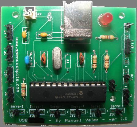
3 Introduction: USBAxes is a card that can manage up to 5 analogical 8 bits axes and 24 pushbuttons. UsbAxes: The operating system recognizes and shapes the board as a common Joystick, plus 3 additional axes and 24 pushbuttons, so it is not necessary any additional software to manage the card. To configure the card, it will be treated as a joystick, allowing to assign buttons and axes to any event in the simulator. Outline and components: - C1 = CAPACITOR 220 nf - C2, C3 = CAPACITORS 22pF - C4, C5 = CAPACITOR 0, 1uF - D1 = LEDS DIODE - IC1 = MICROCONTROLLER 16C745 - J1 = USB CONNECTOR - J2 = POWER SUPPLY 2 PINS CONNECTOR - J3 J14 = CONNECTORS 3 PINS - Q1 = QUARTZ CRYSTAL 6Mhz - R1 = RESISTOR 1K5 - R2 = RESISTOR 10K - R3 = RESISTOR 100R - R5 = RESISTOR 470R - SW1 = RESET ( CONNECTOR 2 PINS ) Description of connectors: J1 = USB connector, allows to connect directly to the computer. Once connected, the computer will recognize the card as a game device. J2 = Power connector, it is a 5V output for little charges, not to be connected to any power supply. J3 a J7 = Conectores Analogic inputs connectors (see connections scheme). J9 a J14 = Pushbuttons / keys connectors, combined with JP1 connector (see connections scheme). Reset for the card microcontroller (not often used). 3


4 Connection of the pushbuttons: The set up of short circuits of the different switches will be done in matrix, that means that joining any pin of B group, to one of G group a switch will be obtained, and successively, according to the following table: JP1 pin8 J8 J14 J13 J12 J11 J10 J9 JP1 pin3 SW1 SW2 SW3 SW4 SW5 SW6 SW7 SW8 JP1 pin4 SW9 SW10 SW11 SW12 SW13 SW14 SW15 SW16 JP1 pin5 SW17 SW18 SW19 SW20 SW21 SW22 SW23 SW24 To better explain the connections, we include an image: 4


5 How to setup the card: We already know the theory on how to connect the IOCard USBAxes, now we will verify and connect it to see the results. In our exercise we will connect the USBAxes card to an USB port and see if our computer recognizes it. It has been recognized, so we will disconnect the card from the USB port and we will connect 4 potentiometers and two push buttons according to the previous table, to make our trial: 5


6 Installation and configuration: This card does not need any software, simply try the connection of the potentiometers and push buttons. The potentiometers are connected pin to pin at ports J3, J4, J5 and J6, and push buttons as follows: switch 4 to J13 and JP1 pin 3, switch 7 to J10 and JP1 pin 3: When all is ready, connect the card to the USB port, if there are no problems the USBAxes card will be recognized and we will go on to verify its operation with potentiometers and switches. 6

7 As seen in the previous image it has recognized axes x, y, z ( throttle ) and rudder, if we move the potentiometers the red bars will change, and also the cursor in the square window, likewise if we press switch 10, it recognizes it as button 4 of the joystick, if we press switch 19, it is recognized as button 7, The installation phase of the card is already finished and as we see, it does not need configuration in the operating system, but it does in the simulator. 7
8 To program the functions of the the USBAxes card in the simulator we must start it and open the section in MODULES>FSUIPC>FSUIPC BUTTONS+SWITCHES, the following screen appears. The main features are marked in colors: The part marked with a red circle is the number of the active joystick ( as in our case we only have one, it gets 0. Should it be the third joystick, it will appear as Joy#2 ). The blue circle indicates the button we have pressed, in our case sw10 that in FSUIPC is the Btn#3. The green circle is the key or function that it is executed in the simulator when sw10 is pressed (in the example is key S, the change views button ), we accept and make a try. If all has gone well, we can do the same thing for all 24 switches. This gives end to this manual. We invite you to read the manuals of the other Opencockpits elements and of the SIOC software and thank you for trusting us. Links of interest: Area of support for clients: 8
IOCards USB Axes Manual. Date:15/03/12 Rev.:2.0
 Date:15/03/12 Rev.:2.0 Index: IOCARDS USB AXES MANUAL... 1 INDEX:... 2 INTRODUCTION:... 3 USBAXES:... 3 Outline and components:... 3 Description of connectors:... 3 CONNECTION OF THE PUSHBUTTONS:... 3
Iocard USB DcMotors Manual. Date:15/02/12 Rev.:2.0
 Iocard USB DcMotors Manual Date:15/02/12 Rev.:2.0 Index: IOCARD USB DCMOTORS MANUAL... 1 INDEX:... 2 INTRODUCTION:... 3 USB DCMOTORS:... 3 Outline and components:... 3 Connectors description:... 4 CONECTIONS:...
OPENCOCKPITS IOCard USBRELAYS INSTALLATION AND USER S MANUAL
 OPENCOCKPITS IOCard USBRELAYS INSTALLATION AND USER S MANUAL INTRODUCTION The USBRelays card is designed to manage up to 7 power relays. We also have in it 5 analogic inputs, to connect up to 5 potentiometers.
Date:15/11/13 Rev.:2.1. IOCards USB Expansion & Master Manual
 Date:15/11/13 Rev.:2.1 IOCards USB Expansion & Master Manual Index: IOCARDS USB EXPANSION & MASTER MANUAL... 1 INDEX:... 2 INTRODUCTION:... 3 USBEXPANSION:... 3 Outline and component:... 3 Description
Manual IOCard USB DimControl. Date:08/18/15 Rev.:1.1
 Manual IOCard USB DimControl. Date:08/18/15 Rev.:1.1 Index: MANUAL IOCARD USB DIMCONTROL... 1 INDEX:... 2 INTRODUCTION:... 3 USB DIMCONTROL:... 3 ESCHEMA:... 3 CONNECTOR DESCRIPTION:... 4 Connector J7
IocardUSB DCMotors Plus Manual. Date:02/08/12 Rev.:1.0
 IocardUSB DCMotors Plus Manual Date:02/08/12 Rev.:1.0 Index: IOCARDUSB DCMOTORS PLUS MANUAL... 1 INDEX:... 2 INTRODUCTION:... 3 USB DCMOTORS PLUS:... 3 SPECIFICATIONS:... 3 SCHEME AND MEASURES:... 4 NOTAS
Connecting Your Rudder Potentiometers to The BU0836 Controller Card.
 Connecting Your Rudder Potentiometers to The BU0836 Controller Card. There are 3 Potentiometers fitted to the rudder pedals. Left Brake, Right Brake and the Rudder itself. This is how to connect them to
OPENCOCKPITS IOCards USBKeys INSTALLATION AND USER S MANUAL
 OPENCOCKPITS INSTALLATION AND USER S MANUAL INTRODUCTION The USBKeys manages automatically matrix keyboards. This card allows manage and control a keyboard via connecting pushbutton in a matrix of 11x8
OPENCOCKPITS IOCard USBOUTPUTS INSTALLATION AND USER S MANUAL
 OPENCOCKPITS IOCard USBOUTPUTS INSTALLATION AND USER S MANUAL INTRODUCTION This card allows us to manage easily up to 64 outputs up to 40V and 500mA on each output, with a total amount of 2,5A. Also, the
PICAXE EXPERIMENTER BOARD (AXE090)
") (AXE00) Description: The PICAXE experimenter board allows circuits for any size/revision of PICAXE chip ( / / ) to be quickly tested using a prototyping breadboard. The experimenter board provides power
(AXE00) Description: The PICAXE experimenter board allows circuits for any size/revision of PICAXE chip ( / / ) to be quickly tested using a prototyping breadboard. The experimenter board provides power
Plasma V2 USB Module
 Plasma V2 USB Module DOC No. : 16411 Rev. : A7-211 Date : 5, 2004 Firmware Rev. : 600-210 Beta Innovations (c) 2004 1 Table of Contents Main Features...4 Introduction...5 Plasma Configuration...6 Mode
Plasma Lite USB Module
 Plasma Lite USB Module DOC No. : 16511 Rev. : A8-100 Date : 6, 2004 Firmware Rev. : 600-100 Beta Innovations (c) 2004 http:\\www.betainnovations.com 1 Table of Contents Main Features...4 Introduction...5
Images Scientific OWI Robotic Arm Interface Kit (PC serial) Article
 Article") Images Scientific OWI Robotic Arm Interface Kit (PC serial) Article Images Company Robotic Arm PC Interface allows real time computer control and an interactive script writer/player for programming and
Images Scientific OWI Robotic Arm Interface Kit (PC serial) Article Images Company Robotic Arm PC Interface allows real time computer control and an interactive script writer/player for programming and
Electronic Lock CodeLock AVR 1 DIY electronic door lock
 Electronic Lock CodeLock AVR 1 DIY electronic door lock CodeLock AVR LCD CodeLock AVR electronic lock is realised with Atmel AVR micro-controller AT90S2313, ATtiny2313 or ATtiny45. 1 user code in the program
B737 IDC Audio Panel Manual. Date:05/23/14 Rev.:1.0
 B737 IDC Audio Panel Manual. Date:05/23/14 Rev.:1.0 Index: B737 IDC AUDIO PANEL MANUAL... 1 INDEX:... 2 INTRODUCTION:... 3 BKI TECHNOLOGY:... 3 WIRING PLAN:... 3 DESCRIPTION OF CONNECTORS:... 3 CONNECTIONS
8051 Microcontroller Interrupts
 8051 Microcontroller Interrupts There are five interrupt sources for the 8051, which means that they can recognize 5 different events that can interrupt regular program execution. Each interrupt can be
Sim-Factory Plasma USB Module. DOC No. : Rev. : A7 Date : 10, 2003 Part No. : (c) 2003 Leo Lacava 1
 2003 Leo Lacava 1") Plasma USB Module DOC No. : 16409 Rev. : A7 Date : 10, 2003 Part No. : 600-100 (c) 2003 Leo Lacava 1 Table of Contents Table of Contents...2 Plasma USB Module...3 Main Features...4 Introduction...5 Plasma
Plasma USB Module DOC No. : 16409 Rev. : A7 Date : 10, 2003 Part No. : 600-100 (c) 2003 Leo Lacava 1 Table of Contents Table of Contents...2 Plasma USB Module...3 Main Features...4 Introduction...5 Plasma
Transcendent Frequency Counter
 Transcendent Frequency Counter with blue 2 x 16 LCD display This manual will guide you how to assemble, test and operate this frequency counter KIT. Features: The transcendent counter has two input channels
SM010, Assembly Manual PCB Version 1.0
 180 SM010, Assembly Manual MATRIXARCHATE 16 8 IO SEQUENTIAL MATRIX SIGNAL ROUTER SM010 1 2 1 2 3 4 5 3 4 5 6 7 8 9 10 11 12 6 7 8 9 10 11 12 13 14 15 16 PROGRAM A B C D E F G H f1 f2 20.000 180 SSSR Labs
1/Build a Mintronics: MintDuino
 1/Build a Mintronics: The is perfect for anyone interested in learning (or teaching) the fundamentals of how micro controllers work. It will have you building your own micro controller from scratch on
Bolt 18F2550 System Hardware Manual
 1 Bolt 18F2550 System Hardware Manual Index : 1. Overview 2. Technical specifications 3. Definition of pins in 18F2550 4. Block diagram 5. FLASH memory Bootloader programmer 6. Digital ports 6.1 Leds and
AKKON USB CONTROLLER BOARD
 TN002 AKKON USB CONTROLLER BOARD USB Microcontroller board with the PIC18F4550 * Datasheet Authors: Gerhard Burger Version: 1.0 Last update: 20.01.2006 File: Attachments: no attachments Table of versions
Shack Clock kit. U3S Rev 2 PCB 1. Introduction
 Shack Clock kit U3S Rev 2 PCB 1. Introduction Thank you for purchasing the QRP Labs Shack Clock kit. This clock uses the Ultimate3S QRSS/WSPR kit hardware, but a different firmware version. It can be used
ARRL ETP Solder Hour Clock Kit Construction Manual
 ARRL ETP Solder 101 24-Hour Clock Kit Construction Manual Do a complete parts check cross checking the individual parts against the parts list. Pay particular attention to the color code for the resistors:
Uzebox JAMMA. Operation manual. (For Uzebox JAMMA Rev. C devices)
") Uzebox JAMMA Operation manual (For Uzebox JAMMA Rev. C devices) Basement Hobbies 2011 Contents Warnings 2 Introduction 3 Materials 4 Overview 5 Installation 6 Operation 7 Troubleshooting 13 Contact 16
Uzebox JAMMA Operation manual (For Uzebox JAMMA Rev. C devices) Basement Hobbies 2011 Contents Warnings 2 Introduction 3 Materials 4 Overview 5 Installation 6 Operation 7 Troubleshooting 13 Contact 16
TIME WIZARD MULTI CLOCK DIVIDER BUILDING GUIDE
 TIME WIZARD MULTI CLOCK DIVIDER BUILDING GUIDE Table of Contents 0. Components List + Tools 0. PCB Sides 03. PCB Assembly 04_. Diode N448 04_. Laying Resistors 04_3. Capacitors 04_4. Quartz 04_5. 78L05
Bill of Materials: 8x8 LED Matrix Driver Game PART NO
 8x8 LED Matrix Driver Game PART NO. 2171031 This Game Maker II kit is a game design platform using a single color 8x8 matrix LED without the need for a shift register or expensive Arduino. The kit includes
BUILDING YOUR KIT. For the Toadstool Mega328.
 BUILDING YOUR KIT For the Toadstool Mega328 www.crash-bang.com @crashbang_proto This work is licensed under a Creative Commons Attribution-ShareAlike 4.0 International License. Congratulations! You re
Homework 5: Circuit Design and Theory of Operation Due: Friday, February 24, at NOON
 Homework 5: Circuit Design and Theory of Operation Due: Friday, February 24, at NOON Team Code Name: Motion Tracking Laser Platform Group No.: 9 Team Member Completing This Homework: David Kristof NOTE:
SRI-02 Speech Recognition Interface
 SRI-02 Speech Recognition Interface Data & Construction Booklet The Speech Recognition Interface SRI-02 allows one to use the SR-07 Speech Recognition Circuit to create speech controlled electrical devices.
DEV-1 HamStack Development Board
 Sierra Radio Systems DEV-1 HamStack Development Board Reference Manual Version 1.0 Contents Introduction Hardware Compiler overview Program structure Code examples Sample projects For more information,
Ocean Controls KT-5193 Modbus Programmable Stepper Motor Controller
 Ocean Controls KT-5193 Modbus Programmable Stepper Motor Controller The Ocean Controls Modbus Programmable Stepper Motor Controller is a four axis multifunction programmable stepper motor controller which
EasyPIC5 Development System
 EasyPIC5 Development System Part No.: MPMICRO-PIC-Devel- EasyPIC5 Overview EasyPIC5 is a development system that supports over 120 8-, 14-, 18-, 20-, 28- and 40-pin PIC MCUs. EasyPIC5 allows PIC microcontrollers
Shack Clock kit PCB Revision: QCU Rev 1 or QCU Rev 3
 1. Introduction Shack Clock kit PCB Revision: QCU Rev 1 or QCU Rev 3 Thank you for purchasing this QRP Labs Shack Clock kit. The kit uses the same PCB and bag of components as some other QRP Labs kits.
8 CHANNEL USB RELAY CARD
 8 CHANNEL USB RELAY CARD Use your computer USB port to connect to the outside world. Total solder points: 363 Difficulty level: beginner 1 2 3 4 5 advanced K8090 ILLUSTRATED ASSEMBLY MANUAL H8090IP-1 Features
RLS-1000B Remote Link Switch
 RLS-000B Remote Link Switch Instruction Manual Computer Automation Technology Inc. 8 W. Atlantic Blvd. #9 Margate, Florida 06 Phone: 9 98-6 Internet: www.catauto.com The RLS-000B provides a method to connect
Thursday, September 15, electronic components
 electronic components a desktop computer relatively complex inside: screen (CRT) disk drive backup battery power supply connectors for: keyboard printer n more! Thursday, September 15, 2011 integrated
B737 NG MOTORIZED THROTTLE SETUP MANUAL PROJECT MAGENTA. Revolution- Simproducts. All Rights Reserved
 B737 NG MOTORIZED THROTTLE SETUP MANUAL PROJECT MAGENTA Revolution- Simproducts All Rights Reserved January 9, 2010 1 CONTENT INTRODUCTION...3 REVISION LIST...4 Installation for PM without any previous
Exclusive 2.5 GHz Frequency Counter
 Exclusive 2.5 GHz Frequency Counter with blue 2 x 16 LCD display This manual will guide you how to assemble, test and tune this frequency counter KIT. Features: Frequency range from 5 MHz to 2.5GHz Factory
Keywords Digital IC tester, Microcontroller AT89S52
 Volume 6, Issue 1, January 2016 ISSN: 2277 128X International Journal of Advanced Research in Computer Science and Software Engineering Research Paper Available online at: www.ijarcsse.com Digital Integrated
Post Tenebras Lab. Written By: Post Tenebras Lab
 Post Tenebras Lab PTL-ino is an Arduino comptaible board, made entirely out of through-hole components. It is a perfect project to learn how to solder and start getting into the world of micro controllers.
EE 354 August 1, 2017 Assembly of the AT89C51CC03 board
 EE 354 August 1, 2017 Assembly of the AT89C51CC03 board The AT89C51CC03 board comes as a kit which you must put together. The kit has the following parts: No. ID Description 1 1.5" x 3.25" printed circuit
solutions for teaching and learning
 RKP18Motor Component List and Instructions PCB layout Constructed PCB Schematic Diagram RKP18Motor Project PCB Page 1 Description The RKP18Motor project PCB has been designed to use PIC microcontrollers
Propeller Project Board USB (#32810)
") Web Site: www.parallax.com Forums: forums.parallax.com Sales: sales@parallax.com Technical: support@parallax.com Office: (916) 624-8333 Fax: (916) 624-8003 Sales: (888) 512-1024 Tech Support: (888) 997-8267
Web Site: www.parallax.com Forums: forums.parallax.com Sales: sales@parallax.com Technical: support@parallax.com Office: (916) 624-8333 Fax: (916) 624-8003 Sales: (888) 512-1024 Tech Support: (888) 997-8267
AN-719 APPLICATION NOTE One Technology Way P.O. Box 9106 Norwood, MA Tel: 781/ Fax: 781/
 APPLICATION NOTE One Technology Way P.O. Box 9106 Norwood, MA 02062-9106 Tel: 781/329-4700 Fax: 781/326-8703 www.analog.com ADuC7024 Evaluation Board Reference Guide MicroConverter ADuC7024 Development
EasyAVR6 Development System
 EasyAVR6 Development System Part No.: MPMICRO-AVR-Devel-EasyAVR6 Overview EasyAVR6 is a development system that supports a wide range of 8-, 14-, 20-, 28- and 40-pin AVR MCUs. EasyAVR6 allows AVR microcontrollers
AVR Intermediate Development Board. Product Manual. Contents. 1) Overview 2) Features 3) Using the board 4) Troubleshooting and getting help
 Overview 2) Features 3) Using the board 4) Troubleshooting and getting help") AVR Intermediate Development Board Product Manual Contents 1) Overview 2) Features 3) Using the board 4) Troubleshooting and getting help 1. Overview 2. Features The board is built on a high quality FR-4(1.6
AVR Intermediate Development Board Product Manual Contents 1) Overview 2) Features 3) Using the board 4) Troubleshooting and getting help 1. Overview 2. Features The board is built on a high quality FR-4(1.6
Goal: We want to build an autonomous vehicle (robot)
") Goal: We want to build an autonomous vehicle (robot) This means it will have to think for itself, its going to need a brain Our robot s brain will be a tiny computer called a microcontroller Specifically
Goal: We want to build an autonomous vehicle (robot) This means it will have to think for itself, its going to need a brain Our robot s brain will be a tiny computer called a microcontroller Specifically
AP3156 Evaluation Module
 Features V IN Range: 2.7V to 5.5V Fully Programmable Current with Single Wire - 32-Step Logarithmic Scale - 20/25mA Max Current per Channel - Four Low Current Settings Down to 50μA - Low IQ (50μA) for
VFO/Signal Generator kit PCB Revision QCU Rev 1 or QCU Rev 3
 1. Introduction VFO/Signal Generator kit PCB Revision QCU Rev 1 or QCU Rev 3 Thank you for purchasing this QRP Labs kit. The QRP Labs kit range is modular. The kit uses the same PCB and bag of components
PIC 28 Pin Board Documentation. Update Version 5.0
 PIC 28 Pin Board Documentation Update 2009.10 Version 5.0 Table of Contents PIC 28 Pin Board Documentation... 1 Table of Contents... 2 Introduction... 3 Circuit Schematic... 4 The following is the Circuit
REVERSE ENGINEERING ANALYSIS SONY PLAYSTATION ONE CONTROLLER
 Rohaan Ahmed 995374385 REVERSE ENGINEERING ANALYSIS SONY PLAYSTATION ONE CONTROLLER INTRODUCTION Reverse engineering is a skill that can provide an engineer with a complete understanding of an artefact
M68HC705L4 PROGRAMMER BOARD APPLICATION NOTE
 M68HC705L4PGMR JUNE 1992 M68HC705L4 PROGRAMMER BOARD (REVision A PWBs only) APPLICATION NOTE INTRODUCTION This application note describes the programming technique used to program and verify the XC68HC705L4
Electronics Construction Manual
 Electronics Construction Manual MitchElectronics 2019 Version 3 04/02/2019 www.mitchelectronics.co.uk CONTENTS Introduction 3 How To Solder 4 Resistors 5 Capacitors 6 Diodes and LEDs 7 Switches 8 Transistors
Bill of Materials: Handheld Game System PART NO
 Handheld Game System PART NO. 2245108 Build your own Handheld Game System with graphics and sound! This game kit includes a custom designed circuit board along with custom built tools and programming to
CEIBO FE-5111 Development System
 CEIBO FE-5111 Development System Development System for Atmel W&M T89C5111 Microcontrollers FEATURES Emulates Atmel W&M T89C5111 4K Code Memory Real-Time Emulation and Trace Frequency up to 33MHz/5V ISP
Quick Start Guide. TWR-S12G128 Scalable platform for automotive applications TOWER SYSTEM
 TWR-S12G128 Scalable platform for automotive applications TOWER SYSTEM Get to Know the TWR-S12G128 Board Secondary Connector On-Board OSBDM External BDM Connecctor Optional External Power Supply CAN Connectors
H89-Z37 DOUBLE-DENSITY FLOPPY CONTROLLER
 H8-Z37 DOUBLE DENSITY FLOPPY CONTROLLER 2015 H89-Z37 DOUBLE-DENSITY FLOPPY CONTROLLER Norberto Collado norby@koyado.com 6/6/2015 Revision History and Disclaimer Revision History Revision Date Comments
Electronics Construction Manual
 Electronics Construction Manual MitchElectronics 2018 Version 1 07/05/2018 www.mitchelectronics.co.uk CONTENTS Introduction 3 How To Solder 4 Resistors 5 Capacitors 6 Diodes and LEDs 7 Switches 8 Transistors
GammaRay USB Module. Beta Innovations DOC No. : Rev. : A2-102 Date : 2, 2004 Part No. : ,
 GammaRay USB Module DOC No. : 16410 Rev. : A2-102 Date : 2, 2004 Part No. : 500-101, 700-100 Beta Innovations (c) 2003 1 Table of Contents Table of Contents...2 GammaRay-64 USB Module...3 GammaRay-256
Sprinkler Controller Assembly Manual
 Sprinkler Controller Assembly Manual V1.0 Doug Jackson VK1ZDJ September 2010 Licence The Sprinkler Controller Design, PCB layout, Manual, and Firmware is Copyright 2010, by Douglas Jackson, VK1ZDJ. This
8051 Intermidiate Development Board. Product Manual. Contents. 1) Overview 2) Features 3) Using the board 4) Troubleshooting and getting help
 Overview 2) Features 3) Using the board 4) Troubleshooting and getting help") 8051 Intermidiate Development Board Product Manual Contents 1) Overview 2) Features 3) Using the board 4) Troubleshooting and getting help 1. Overview 2. Features The board is built on a high quality FR-4(1.6
8051 Intermidiate Development Board Product Manual Contents 1) Overview 2) Features 3) Using the board 4) Troubleshooting and getting help 1. Overview 2. Features The board is built on a high quality FR-4(1.6
CEIBO FE-51RD2 Development System
 CEIBO FE-51RD2 Development System Development System for Atmel AT89C51RD2 Microcontrollers FEATURES Emulates Atmel AT89C51RD2 60K Code Memory Real-Time Emulation Frequency up to 40MHz / 3V, 5V ISP and
CONTENTS BIGAVR2 KEY FEATURES 4 CONNECTING THE SYSTEM 5 INTRODUCTION 6
 CONTENTS BIGAVR2 KEY FEATURES 4 CONNECTING THE SYSTEM 5 INTRODUCTION 6 Switches 7 Jumpers 8 MCU Sockets 9 Power Supply 11 On-board USB 2.0 Programmer 12 Oscillator 14 LEDs 15 Reset Circuit 17 Push-buttons
S USB-PC Connection (Cable Not Included) S USB Powered (No External Power Supply Required) S Real-Time Data Acquisition Through the USB
 S USB Powered (No External Power Supply Required) S Real-Time Data Acquisition Through the USB") 19-5610; Rev 1; 8/11 MAXADClite Evaluation Kit General Description The MAXADClite evaluation kit (EV kit) evaluates the MAX11645, Maxim's smallest, very-low-power, 12-bit, 2-channel analog-to-digital converter
19-5610; Rev 1; 8/11 MAXADClite Evaluation Kit General Description The MAXADClite evaluation kit (EV kit) evaluates the MAX11645, Maxim's smallest, very-low-power, 12-bit, 2-channel analog-to-digital converter
EVAL-ADG2128EB. Evaluation Board I 2 C CMOS, 8 12 Analog Switch Array with Dual/Single Supplies FEATURES DESCRIPTION
 Evaluation Board I 2 C CMOS, 8 12 Analog Switch Array with Dual/Single Supplies EVAL-ADG2128EB FEATURES Full featured evaluation board for ADG2128 Various link options Direct hook up to USB port of PC
BASIC-Tiger Application Note No. 030 Rev A joystick for the Tiger. Gunther Zielosko. 1. Basics
 A joystick for the Tiger Gunther Zielosko 1. Basics There are many ways in computer technology to convert analog movement into data that is understandable for the computer, thinking about e.g. computer
ATmega48/88/168 Development Board
 ATmega// Development Board This is versatile development board for AVR microcontrollers ATmega//. It is good for testing and debugging embedded programs. It has many built-in peripheries connected to microcontroller
UM2461 User manual. SPC584B-DIS Discovery Board. Introduction
 User manual SPC584B-DIS Discovery Board Introduction The SPC584B-DIS is a low-cost development board to evaluate and develop applications with the microcontroller SPC584B70E1 in etqfp 64-pin package. This
Zippy AVR Programmer. Zippy Programmer Features. Lomae Pty Ltd PO BOX 1297 Baulkham Hills, NSW,1755 ACN
 PO BOX 97 ACN 0 80 56 Zippy AVR Programmer Introduction When Atmel released their 8 Bit AVR Microcontroller range, they also released a complete development system that allowed engineers to start developing
2 in 1. BigAVR User s Manual AVR. MikroElektronika. Software and Hardware solutions for Embedded World
 SOFTWARE AND HARDWARE SOLUTIONS FOR THE EMBEDDED WORLD - Books - Compilers User s Manual 2 in 1 USB 2.0 IN-CIRCUIT PROGRAMMER ATMEL AVR DEVELOPMENT BOARD With useful implemented peripherals, plentiful
VG-305A AC Traffic Light Controller Kit
 Galak Electronics Electronic kits and components Website: GalakElectronics.com Email: sales@galakelectronics.com Phone: (302) 832-1978 VG-305A AC Traffic Light Controller Kit Thank you for your purchase
Mini-TNC Rev 0711 is designed exclusively to work as an APRS TNC.
 Fox Delta Amateur Radio Projects & Kits Mini-TNC Technical Details and Schematic: Mini-TNC - A 1200-Baud Packet TNC Rev. 0711 Completed Mini-TNC: Mini-TNC Rev 0711 is designed exclusively to work as an
CORTEX Microcontroller and Joystick User Guide
 This is a User Guide for using the VEX CORTEX Microcontroller and VEX Joystick. Refer to the VEX Wiki (http://www.vexforum.com/wiki/index.php/vex_cortex_microcontroller) for updates to this document. 1.
High Power (15W + 15W) Stereo Amplifier
 Stereo Amplifier") High Power (15W + 15W) Stereo Amplifier Build Instructions Issue 1.0 Build Instructions Before you put any components in the board or pick up the soldering iron, just take a look at the Printed Circuit
High Power (15W + 15W) Stereo Amplifier Build Instructions Issue 1.0 Build Instructions Before you put any components in the board or pick up the soldering iron, just take a look at the Printed Circuit
N8VEM S-100 BACKPLANE VERSION 04 MAY 3, 2015 J.B.
 N8VEM S-100 BACKPLANE VERSION 04 MAY 3, 2015 J.B. Background. This board is a copy of Andrew Lynch s Version 03 board (with 8 slots) but with added features. Added features: 9 SLOT Active Termination (copied
OSC Ring Type Ring or Resonator type (optional) RESET Pin No Yes
 RESET Pin No Yes") General Description Features est Series is a series of 3 to 340 seconds single chip high quality voice synthesizer IC which contains one 4-bit Input port (provided for est005 and above); three 4-bit I/O
General Description Features est Series is a series of 3 to 340 seconds single chip high quality voice synthesizer IC which contains one 4-bit Input port (provided for est005 and above); three 4-bit I/O
PRELIMINARY TECHNICAL DATA
 a Preliminary Technical Data FEATURES Evaluation Board is designed to be used together with accompanying software to implement a fully functional Three-Phase Energy Meter (Watt-Hour Meter). Easy connection
Storage Card Interface Kit
 Storage Card Interface Kit for MultiMediaCards(MMC) and Secure Digital Cards (SD) MMSD3K The MMSD3K is complete development kit interfaced to a SD or MMC card. This board ideal for projects that involve
MAXQ622 Evaluation Kit Evaluates: MAXQ622
 General Description The MAXQ622 evaluation kit (EV kit) provides a proven platform for conveniently evaluating the capabilities of the MAXQ622 low-power, 16-bit, RISC microcontroller with USB interface
EVAL-ADT7516. SPI -/I 2 C -Compatible, Temperature Sensor, 4-Channel ADC and Quad Voltage Output DAC FEATURES APPLICATIONS
 SPI -/I 2 C -Compatible, Temperature Sensor, 4-Channel ADC and Quad Voltage Output DAC EVAL-ADT7516 FEATURES Easy evaluation of the ADT7516 Can be used to emulate ADT7517 and ADT7519 Evaluation software
GLiPIC Ver C Assembly manual Ver 1.0
 GLiPIC Ver C Assembly manual Ver 1.0 Last Rev 1.1 Oct 30, 2001 Author: Ranjit Diol Disclaimer and Terms of Agreement As with any kit, only the individual parts supplied are guaranteed against defects and
CAT310DB1 DEMONSTRATION BOARD FOR CAT CHANNEL LED DRIVER
 APPLICATION NOTE WWW.CATALYST-SEMICONDUCTOR.COM CAT30DB DEMONSTRATION BOARD FOR CAT30 0 CHANNEL LED DRIVER Denisa Stefan, Application Engineer Cornel Rotaru, Application Engineer. INTRODUCTION This document
CEIBO FE-W7 Development System
 CEIBO FE-W7 Development System Development System for Winbond W7xxxx Microcontrollers FEATURES Emulates Winbond W77xxx or W78xxx Microcontrollers 125K Code Memory Real-Time Emulation Frequency up to fmax
AVR-M Rev 5 ASSEMBLY
 AVR-M Rev 5 ASSEMBLY The AVR_M is a very compact self contained Atmel AVR mcu controller board. It includes an onboard serial programmer (via PC com port), an I2C eeprom and can use a Mega163, Mega16 or
Rapid40i PIC Prototyping PCB User Manual
 Description This is a PCB designed to facilitate the rapid prototyping of a device based on a 40 pin Microchip PIC microcontroller. To allow users to focus on their application, we take care of key housekeeping
Rapid28iXL PIC Prototyping PCB User Manual
 Description Features This is a PCB designed to facilitate the rapid prototyping of a device based on a 28 pin Microchip PIC microcontroller. To allow users to focus on their application, we take care of
Altera EP4CE6 Mini Board. Hardware User's Guide
 Altera Hardware User's Guide 1. Introduction Thank you for choosing the! is a compact FPGA board which is designed based on device. It's a low-cost and easy-to-use platform for learning Altera's Cyclone
8051 Microcontroller
 8051 Microcontroller The 8051, Motorola and PIC families are the 3 leading sellers in the microcontroller market. The 8051 microcontroller was originally developed by Intel in the late 1970 s. Today many
PVK40. User's manual. Feature Rich Development and Educational Kit for 40-pin Microchip PIC microcontrollers
 PVK40 User's manual Feature Rich Development and Educational Kit for 40-pin Microchip PIC microcontrollers CONTENTS PVK40 3 On-board peripherals: 3 Power supply 4 Microcontroller 4 Reset circuitry 4 Oscilator
USB Controlled DMX interface
 USB Controlled DMX interface Control DMX fixtures using a PC and USB interface. Stand-alone test function that outputs all 512 channels at a time, with adjustable levels. Total solder points: 117 Difficulty
HFRD REFERENCE DESIGN High-Frequency XFP Host Board. Reference Design: (Includes Integrated RS-232 to I 2 C Conversion)
") Reference Design: HFRD-18.0 Rev. 7; 11/09 REFERENCE DESIGN High-Frequency XFP Host Board (Includes Integrated RS-232 to I 2 C Conversion) Reference Design: High-Frequency XFP Host Board Table of Contents
Reference Design: HFRD-18.0 Rev. 7; 11/09 REFERENCE DESIGN High-Frequency XFP Host Board (Includes Integrated RS-232 to I 2 C Conversion) Reference Design: High-Frequency XFP Host Board Table of Contents
Wireless LAN and Bluetooth Module Evaluation Board
 Wireless LAN and Bluetooth Module Evaluation Board This evaluation board is an object for experiment of operation, and does not guarantee quality. Moreover, the conditions of a module of operation are
Rapid40iXL PIC Prototyping PCB User Manual
 Description This is a PCB designed to facilitate the rapid prototyping of a device based on a 40 pin Microchip PIC microcontroller. To allow users to focus on their application, we take care of key housekeeping
Uzebox Kit Assembly Guide
 Uzebox Kit Assembly Guide V1.3 Page 1 of 18 Revision History Version Date Author Description 1.0 01-Nov-2012 A.Bourque Initial release 1.1 6-Nov-2012 A.Bourque Minor corrections 1.2 28-Jan-2014 A.Bourque
QUICK START GUIDE FOR DEMONSTRATION CIRCUIT 824 MULTIDISPLAY LED CONTROLLER
 LTC3208 WARNING: The LEDs on this demo board produce very bright light. Do not look directly at LEDs when power is applied. Serious eye damage may occur. DESCRIPTION Demonstration circuit 824 is a multi-display
Figure 2.1 The Altera UP 3 board.
 Figure 2.1 The Altera UP 3 board. USB Port PS-2 Port USB PHY Chip Heat Sink Parallel Port B B VGA Port I2C PROM Chip... JP19 Headers for I2C Bus Signals J3 Mounting Hole Santa Cruz Expansion Long Connector
SPIRIT. Phase 5 Analog Board Computer and Electronics Engineering
 SPIRIT Phase 5 Analog Board Computer and Electronics Engineering In this exercise you will assemble the analog controller board and interface it to your TekBot. Print out the schematic, silkscreen and
QUASAR PROJECT KIT # ATMEL AVR PROGRAMMER
 This kit is a simple but powerful programmer for the Atmel AT90Sxxxx ( AVR ) family of microcontrollers. The Atmel AVR devices are a low-power CMOS 8-bit microcontroller using a RISC architecture. By executing
solutions for teaching and learning
 RKOneAnalogue Component List and Instructions PCB layout Constructed PCB Schematic Diagram RKOneAnalogue Software Development PCB Page 1 Description The RKOneAnalogue software development PCB has been