Articulate Robot Controller - RCA620
|
|
|
- Lauren Boone
- 5 years ago
- Views:
Transcription

1 Articulate Robot Controller - RCA620 User Manual Original Instruction


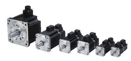


2 INDUSTRIE 4.0 Best Partner Multi Axis Robot Pick-and-place / Assembly / Array and packaging / Semiconductor / Electro-Optical industry / Automotive industry / Food industry Articulated Robot Delta Robot SCARA Robot Wafer Robot Electric Gripper Integrated Electric Gripper Rotary Joint Single Axis Robot Precision / Semiconductor / Medical / FPD KK, SK KS, KA KU, KE, KC Direct Drive Rotary Table Aerospace / Medical / Automotive industry / Machine tools / Machinery industry RAB Series RAS Series RCV Series RCH Series Ballscrew Linear Guideway Precision Ground / Rolled Super S series Super T series Mini Roller Ecological & Economical lubrication Module E2 Rotating Nut (R1) Energy-Saving & ThermalControlling (C1) Heavy Load Series (RD) Ball Spline Automation / Semiconductor / Medical Ball Type--HG, EG, WE, MG, CG Quiet Type--QH, QE, QW, QR Other--RG, E2, PG, SE, RC Medical Equipment Bearing Hospital / Rehabilitation centers / Nursing homes Robotic Gait Training System Hygiene System Robotic Endoscope Holder Machine tools / Robot Crossed Roller Bearings Ball Screw Bearings Linear Bearing Support Unit AC Servo Motor & Drive Driven Tool Holders Semiconductor / Packaging machine /SMT / Food industry / LCD Drives-D1, D1-N, D2T Motors-50W~2000W All kinds of turret VDI Systems Radial Series, Axial Series, MT BMT Systems DS, NM, GW, FO, MT, OM, MS Linear Motor Torque Motor (Direct Drive Motor) Automated transport / AOI application / Precision / Semiconductor Iron-core Linear Motor Coreless Linear Motor Linear Turbo Motor LMT Planar Servo Motor Air Bearing Platform X-Y Stage Gantry Systems Inspection / Testing equipment / Machine tools / Robot Rotary Tables-TMS,TMY,TMN TMRW Series TMRI Series
3 Warranty Terms and Conditions The period of warranty shall commence at the received date of HIWIN product (hereafter called product ) and shall cover a period of 12 months. The warranty does not cover any of the damage and failure resulting from: The damage caused by using with the production line or the peripheral equipment not constructed by HIWIN. Operating method, environment and storage specifications not specifically recommended in the product manual. The damage caused by changing installation place, changing working environment, or improper transfer after being installed by the professional installer. Product or peripheral equipment damaged due to collision or accident caused by improper operation or installation by the unauthorized staff. Installing non-genuine HIWIN products. The following conditions are not covered by the warranty: Product serial number or date of manufacture (month and year) cannot be verified. Using non-genuine HIWIN products. Adding or removing any components into/out the product without authorized. Any modification of the wiring and the cable of the product. Any modification of the appearance of the product; removal of the components inside the product. e.g., remove the outer cover, product drilling or cutting. Damage caused by any natural disaster. i.e., fire, earthquake, tsunami, lightning, windstorms and floods, tornado, typhoon, hurricane etc. HIWIN does not provide any warranty or compensation to all the damage caused by above-mentioned circumstances unless the user can prove that the product is defective. For more information towards warranty terms and conditions, please contact the technical stuff or the dealer who you purchased with. 1
4 Improper modification or disassemble the robot might reduce the robot function, stability or lifespan. The end-effector or the cable for devices should be installed and designed by a professional staff to avoid damaging the robot and robot malfunction. Please contact the technical stuff for special modification coming from production line set up. For the safety reason, any modification for HIWIN product is strictly prohibited. 2
5 1. Safety Information Safety Responsibility and Effect Safety Precautions This chapter explains how to use the robot safely. Be sure to read this chapter carefully before using the robot. The user of the HIWIN industrial robot has responsibility to design and install the safety device meeting the industrial safety regulations in order to ensure personal safety. In compliance with the safety information on industrial robot described in this manual can t guarantee that HIWIN robot will not occur any safety problems. This machine is defined as a partly completed machinery, the associated hazards must be handled by system integrator in accordance with ISO /-2. A safety-related part of control system (SRP/CS) should conform to the requirement of performance level d and category 3 according to ISO The installation for emergency functions shall be defined by the system integrator in accordance with ISO /2. Safety Operation Principle Before connecting the power supply for HIWIN industrial robot startup assembly procedure, check whether the specification of factory output voltage matches the specification of input voltage of the product. If it does not match, ensure to use the corresponding transformer (HIWIN optional transformer is recommended). Emergency Stop button (on Teach Pendant or from external emergency stop switch) must be pressed before turning off the power, and then switch off the power switch. While connecting to the external I/O or the signal, please operate in the condition that the power switch is turned off to prevent from a shortcut caused by mistaken touch in the process, and resulting in damage. 3
6 2. Description Related to Safety I. Safety Symbols C08UE Carefully read the instructions in the user manual prior to robot use. The following shows the safety symbols used in this user manual. Symbol Description Failure to follow instructions with this symbol may result in serious hazard or personal injury. Please be sure to comply with these instructions. Failure to follow instructions with this symbol may result in personal injury or product damage. Please be sure to comply with these instructions. Failure to follow instructions with this symbol may result in poor product performance. Please be sure to comply with these instructions. II. Working Person The personnel can be classified as follows Operator: Turns robot controller ON/OFF Starts robot program from operator s panel Reset system alarm Programmer or teaching operator: Turns robot controller ON/OFF Starts robot program from operator s panel Reset system alarm Teaches robot Maintenance engineer: Turns robot controller ON/OFF Starts robot program from operator s panel Reset system alarm Teaches robot Does maintenance, adjustment, replacement Programmer and the maintenance engineer must be trained for proper robot operation. 4
7 3. Precautions 3.1 Common Safety Issues C08UE All operating procedures should be assessed by professional and in compliance with related industrial safety regulations. When operating robot, operator needs to wear safety equipment, such as workwear for working environment, safety shoes and helmets. When encountering danger or other emergency or abnormal situation, please press the emergency stop button immediately. After danger is eliminated, move the robot away with low speed in manual mode. When considering safety of the robot, the robot and the system must be considered at the same time. Be sure to install safety fence or other safety equipment and the operator must stand outside the safety fence while operating the robot. A safety zone should be established around the robot with an appropriate safety device to stop the unauthorized personnel from access. While installing or removing mechanical components, be aware of a falling piece which may cause injury to operator. Ensure the weight of workpiece does not exceed the rated load or allowable load moment at wrist. Exceeding these values could lead to the driver alarm or malfunction of the robot. Do not climb on manipulator. Do not store the machine in the environment with corrosion and flammable gas or close to the flammable object. Do not operate the machine in the environment with moisture, water or grease. Do not operate the machine at the place where vibration or the strong impact occurs. 5
8 Do not immerse the electric wires into grease or water. Do not connect or operate the machine with wet hands. Do not operate the machine in potentially explosive environment. Please ensure the controller is grounded. Keep hands away from the inner part of the controller while it is connecting to the power or during operating. Do not touch the heat sink, regenerative resistance, the power supply or the computer inside the controller while it is operating due to its high temperature. Be sure power is disconnected prior to repair and maintenance, and ensure to operate under the condition of no electrical shock risk. Do not disassembly the controller without permission. If there s any issues, please contact our engineers. The personnel installing robot should be trained and licensed. To ensure personal safety, robot installation must comply with this manual and related industrial safety regulations. The control cabinet should not be placed near high voltage or machines that generate electromagnetic fields to prevent interference that could cause the robot to deviation or malfunction. Using non-hiwin spare parts to repair may cause robot damage or malfunction. Beware of the heat generated by the controller and servo motor. Do not overbend the cable to avoid poor circuit contact or unexpected damage. Do not stand on the controller or put heavy objects on it. 6
9 Do not block the vent or put foreign objects into the controller. Please ensure the controller is fixed on the base. Do not pull the connector violently or twist the electric wires excessively. Do not frequently switch ON/OFF the power switch and the control button. Please ensure that the robot, the emergency stop switch and the controller are functioning properly before performing any work. Do not shutdown the power switch during the operation. C08UE Do not open, modify, disassemble and maintain the machine without permission. The power must be disconnected when the machine does not operate in a long time. Do not turn off the power of the controller when modifying the program or parameter. Otherwise, the data stored in the controller will be damaged. After the brake of a servo motor is released, the robot will be moved due to gravity and it may injured the operator. The industrial robots can be applied for the different industrial environments. When the operating procedures are interrupted, the special attention should be paid during the troubleshooting. 7
10 3.2 Operation 3.3 Maintenance C08UE Teaching, jogging or programming should be done outside of the safety fence. If it is inevitable to enter the safety fence, press the emergency stop button before entrance. Operation should be restricted at low speed and beware of surrounding safety. All operations shall be executed by trained staff. Please contact us if the procedure not specified by HIWIN is needed. Please contact us if the replacement of the component not specified by HIWIN is needed. Be sure to carry out regular maintenance, otherwise it will affect the service life of the robot or other unexpected danger. Prior to repair and maintenance, please switch off power supply. Maintenance and repair should be performed by a qualified operator with a complete understanding of the entire system to avoid risk of robot damage and personal injury. When replacing the components, avoid foreign object going into the robot. 8
11 3.4 End Effector The end effector can be classified as two types: A. Gripper: Used to load and unload, such as pneumatic gripper, electric gripper and vacuum sucker. B. Tool: Used to process, such as welding, cutting and surface treatment. More attention must be paid to the design of the end effector to prevent power loss or any other errors that could lead to workpiece falling or damage. The tool-type end effector is usually equipped with high voltage, high temperature and active rotary shaft. Special attention should be paid to the operating safety. The end effector should be mounted firmly on the robot to avoid workpiece fall during operation which may cause personal injury or hazard. The end effector may be equipped with its own control unit. During installation, pay attention to installed location. Ensure that the control unit does not interfere with robot operation. The gripper-type end effector should prevent the workpiece from dropping or damaging when the robot experiences a power error or other errors. If potential dangers or abnormal situations exist when using end effector, the associated hazards must be handled by the system integrator in accordance with the related standards Pneumatic, Hydraulic System When using the pneumatic or hydraulic system, the gripped workpiece may fall due to insufficient pressure or gravity. The pneumatic or hydraulic system must be equipped with the relief valve, so that it can be applied in an emergency. More attention should be paid to the pressure remained in the pneumatic systems after the power is disconnected. 9
12 3.6 Emergency Stop Switch The internal pressure must be released before the pneumatic systems are maintained. More attention should be paid to the pressure in the pneumatic system as it is several times more than the atmosphere pressure. The robot or other control component should have at least one device for immediate halt, such as an emergency stop switch. The emergency stop button must be installed in an easily accessible location for quick stop. While executing an emergency stop, power to the servo motor will be cut, and all movements will be stopped. And the control system will be shut down. Emergency stop should be reset if the restoration of operating procedure is wanted. Avoid using emergency stop to replace a normal stop procedure. This could reduce the lifespan of the robot. The drive power and the control system will be disconnected to stop all actions during the emergency stop. If you want to restart the procedures, you should reset the emergency stop switch. Emergency stop established an immediate stop: Immediately stop the robot system, and disconnect the driver power. The emergency stop switch is used for emergency stop only. The HIWIN robot is equipped with two emergency stop switches, where one is installed on the teach pendant and the other is directly connected to the controller via a cable. If additional emergency stop switches are required, other connecting method can be applied for the same purpose. Based on the relevant industrial safety regulations, the emergency stop switch is directly connected to 10
13 the controller of the robot via the physical wires. If the version of the braking is not applied to the whole axis, once the emergency stop is executed and the heavy objects are loaded on the robot end, the axis without brake will move due to gravity. This attention must be paid for safety issue. 4. Intended use HIWIN robots are industrial robots and intended for pick-and-place, handling, assembling, deburring, grinding and polishing. Use is only permitted under the specified environment, for more detailed information please see section 2.5 environmental conditions. Use is not permitted under the following conditions: Use in potentially explosive environments Use without performing risk assessments Transportation of people and animals Operation outside the allowed operating parameters 5. Disposal The disposal of HIWIN robot shall be in accordance with the local environmental regulations. 11
14 Content 1. Specifications Standard Specification Description of Model Name Standard and Optional Equipment Appearance Dimensions Recommended installation method Operating Environment Sticker and Label Installation The function of each component outside the controller Power Connection Instruction of Controller ON/OFF Procedure Controller Boot/Shutdown Program Description Motor Cable Connection (CN2) Emergency Stop Switch Connection (CN3) External Input/ Output Function I/O Digital I/O Digital I/O Expansion Module (Optional) Network Connection Port Teach Pendant Maintenance UPS Battery (Only For Non-CE Version) Version Date Applicable Scope Note Jan. 5, 2018 RCA620 First edition Aug. 31,2018 RCA Sept. 18,2018 RCA Added transformer and other cable connector. 2. Added fuse accessory kit. 1. Modified UPS battery maintenance chapter 12
15 1. Specifications 1.1 Standard Specification The following table shows the standard specifications of the robot controller. Item HIWIN Robot Controller Model No. RCA620 Positioning control PTP(point-to-point) CP(continuous path) Joint control AC servo control Operating system HRSS Memory Fixed point 5000 capacity Step number Teaching method Teach pendant Communication interface Ethernet 1 USB 1 Emergency stop input Input:1 Input:8 Function I/O External I/O Output:8 Digital I/O Input:16 Output:16 Input power range (VAC) Three-phase Power Power capacity (KVA) 3.5 Power frequency (Hz) 50/60 Voltage drop (msec) 10 or less Rating output current (A) 22 Weight (kg) 80 Protection rating IP54 Temperature range for workplaces ( ) 0-40 Relative humidity (%RH) Grounding Below100Ω 13

16 1.2 Description of Model Name Model example RCA Maximum Reach Radius mm mm Series RCA620 RCA620 Series articulated robot controller 14
17 1.3 Standard and Optional Equipment Standard and optional equipment for 620 series robot controller. Item HIWIN Part No. Standard Optional Remark CN2, Power Signal Cable 5M AH300T01 Refer to CH 2.5 Controller Door Key N/A Attached to controller Teach Pendant AH300U01 Refer to CH 4 CN3 Emergency Stop Switch Unit 5M 4C7006F1 Refer to CH 2.6 Connector Accessory Kit 4C201GN1 Refer to table 1 Fuse Accessory Kit 4C2024Q1 Refer to table 2 Functional I/O Module 4C201GM1 Refer to CH.3.1 Digital I/O Module 4C201GP1 Refer to CH 3.2 External I/O Extension Module (Include expansion card and wiring set) 4C201GQ1 Refer to CH 3.3 (Note 1) UPS battery (For Non-CE version) 462C0097 Refer to CH 5.1 Transformer Power Cable 4C704YW1 Refer to CH 2.2 2KVA Transformer 462D0046 Refer to CH 2.2 2KVA Transformer, Box, UL version(note 2) 462D004B Refer to CH 2.2 *Note 1: Maximum Expansion - 16 Input and 16 Output (Optional) *Note 2: The above transformers are all I/P380V-415V-480V-575V, O/P220V Table 1: Connector accessory kit item content: Item HIWIN Part No. Quantity D-Sub Connector 15P VZ 1 D-Sub Connector 26P W1 1 D-Sub Connector 25P W0 2 D-Sub Connector Dust Cover 15P, 26P VW 2 D-Sub Connector Dust Cover 25P VX 2 Table 2: Fuse accessory kit item content: Item HIWIN Part No. Quantity Fuse 2A N 1 Fuse 5A D 1 Fuse 1.5A Fuse 20A Z 3. 15
18 1.4 Appearance Dimensions The following show the appearance dimensions of the robot controller (unit: mm). Front view Side view 16
19 1.5 Recommended installation method Controller should be placed upright (as shown in the following figure).please keep 800mm clearance from the front door for opening the front door and cable installation. Unit: mm Controller should be placed upright as in above CAUTION figure. It is forbidden to install the controller 90 degree or 180 degree from the upright posture. 17
20 1.6 Operating Environment The robot controller employs the IEC protection rating as IP54. WARNING The controller should not be placed at the environment with moisture, with high temperature, under direct sunlight or potentially explosive environment. Please keep the controller away from the strong electric field or the magnetic field. Please place the controller at flat place, and avoid shaking. Filter for heat exchanger needs to be cleaned regularly. When installation, please reserve at least 160mm space from the wall for dissipating heat. Please make sure the controller is fixed stably by the screws. 18

21 1.7 Sticker and Label The following shows the appearance stickers and labels on the robot controller. Front view


22 No. Illustration Description 1 Controller specification 2 Do not remove Teach Pendant when the power is turned on 3 Beware of electric shock 4 Danger: authorized proffesionals only 20
23 2. Installation 2.1 The function of each component outside the controller No. Item No. Item 1 Power Switch 11 Reserved for I/O expansion 2 Door Lock 12 CN5 I1 3 Emergency stop button 13 CN5 O1 4 Power indicator 14 Emergency Stop Connector(CN3) 5 Heat exchanger 15 Function I/O connector (CN10) 6 Teach pendant hanger 16 Reserved for expansion 7 Cover for regenerative resistor 17 Network Connector 8 Main Power Source 18 USB Connector 9 Motor Connector(CN2) 10 Teach Pendant Connector(CN4) 21
24 2.2 Power Connection The picture below is an example of power connection structure. This controller needs to be supplied with three-phase AC V, and the ground connection should be separated from main power breaker. Note 1 No. RCA620 series basic connection structure 1 CN2 Power & Signal Cable 2 CN4 Teach Pendant 3 CN3 Emergency Stop Switch 4 Transformer(Note 1) 5 Transformer power cable(note 1) *Note 1: RCD403 series robot arm controller input voltage specification is threephase 220V. If the power supply specifications of the client are different, the transformer must be connected in series. 22
25 Controller side Controller side Controller side Controller side Input Power Type A(380V) Input Power Type B(415V) Input Power Type C(480V) Input Power Type D(575V) Power Input Power Input Power Input Power Input 23
 Operate the robot to a safe posture, and then stop the motion. (2) Press the emergency stop button. (3) Turn the power switch on the controller panel to state O-OFF.")

26 2.3 Instruction of Controller ON/OFF Procedure No. Item Illustration Description Controller ON: After the power is connected, turn the power switch to state -ON. The power indicator will turn ON. 1 Power Switch Controller OFF: (1) Operate the robot to a safe posture, and then stop the motion. (2) Press the emergency stop button. (3) Turn the power switch on the controller panel to state O-OFF. (4) After controller shutting down, power indicator will turn OFF. 2 Power Indicator When robot controller is ON, this indicator will turn ON. When robot controller is OFF, this indicator will turn OFF. WARNING If you want to stop a moving robot, you should go through the normal procedure and press the stop button instead of the emergency stop. Please stop the robot and press the emergency stop button before turning it off. Directly cut off the power while robot is moving may cause an unexpected danger. 24

27 2.4 Controller Boot/Shutdown Program Description Boot Power on by flipping up the power switch. Shutdown HIWIN industrial robot (HRSS version above, if having previous version, it is highly recommended to update the newest version) provided with 2 types of shutdown program. Software shutdown and Digital input control shutdown respectively, choose either one to execute: 1. Using software to shutdown - Procedure for shutting down are as follows: (1) Stop the motion of the robot manipulator. (2) Press the emergency stop button. (3) Press the software shutdown button. (4) Wait at least 5 seconds before switching off the power. (Switch off the controller switch or cut off the main power directly) CAUTION Operator must not leave until the power switch is switched off. 25


28 2. Using digital input (DI) to control shutdown Please set the option of DI/DO in the HRSS software program. The setting method is as follows: Step 1: Enter HRSS function page, click Start-up -> System Setting -> DIO Setting Step 2: DI setting DO Setting Please select the DI pin to be set by the customer. Please select the DO pin to be set by the customer. 26
 Two types of method: (select either one to execute) a. After connecting digital input (DI) to trigger shutdown, wait at least 5 seconds before switching off the power.")
29 Step 3: Please press SAVE after setting. Procedure for shutting down are as follows: (1) Stop the motion of the robot manipulator. (2) Press the emergency stop button. (3) Two types of method: (select either one to execute) a. After connecting digital input (DI) to trigger shutdown, wait at least 5 seconds before switching off the power. (Switch off the controller switch or cut off the main power directly) b. After connecting digital input (DI) to trigger shutdown, the controller should receive the digital output (DO) feedback to switch off the power. (Automatically generated by the system without additional control) (Switch off the controller switch or cut off the main power directly) CAUTION Operator must not leave until the power switch is switched off. 27
30 Digital Input Shutdown Timing: WARNING If the above procedure is not completed, please do not directly switch off the power switch on the controller or cut off the main power. Improper shutdown could cause damage to the controller. Please wait for 30 seconds to reboot. Do not reboot immediately after switching off the power switch. If stopping a robot in motion is required, please avoid using emergency button. To stop the program, press the stop button. Please stop the motion of the manipulator before shutting down. Then perform the shutdown procedure to avoid unexpected danger when the power is cut off during the motion. 28

31 2.5 Motor Cable Connection (CN2) Description: The motor cable connects the robot and the controller with a 5m cable. Connection method: The motor connection port on the controller is CN2 connector which is designed mistakeproofing. If it cannot be plugged in, please flip and connect it again. Plug the motor cable into CN2 connector, and buckle up the safety lock indeed. WARNING Plug the connector in the direction parallel to the pins to avoid the internal pins being crooked and deformed. According to different operating condition, the temperature of the cable would rise slightly. Remove plastic cover before connection. Please avoid severe impact while installation. 29
 is a button box with a 5m wire. It should be placed at the position, which is convenience to reach.")

32 2.6 Emergency Stop Switch Connection (CN3) Description: Connector CN3 is a female DSUB-15 connector for emergency stop. Emergency stop switch (optional equipment) is a button box with a 5m wire. It should be placed at the position, which is convenience to reach. DSUB-15 soldering connector is included in the connector kit. Emergency stop switch wiring diagram CN3 CAUTION Please ensure that the emergency stop switch and the emergency stop on the teach pendant are secured before operates the robot. When using emergency stop connector, please make sure the connection is secure, Maximum contact current is 6A. Be sure to use D-SUB 15P connector to connect to CN3 connector. Do not wire without proper connector. 30


33 Connection Method: The connector of emergency stop device on controller is CN3 which is designed fool-proofing. If it cannot be plugged in, please flip and connect it again. Please remove protection cover before connection. Plug the connector into CN3 and secure the screws indeed. Be sure to release the emergency stop switch before moving the robot. DANGER The emergency stop device must be connected with the controller and be placed at the position accessible to operator. Wrong way of using can cause a severe damage or loss of life and property. CAUTION Before operates the robot, check if emergency stop switch and emergency stop switch on the teach pendant are in reset states. 31

34 3. External Input/ Output There are two types of controller external I/O: (1) Function I/O (FI/O) specific function I/O (2) Digital I/O (DI/O) external I/O for customer s configuration 3.1 Function I/O Description: 1. Standard equipment has function I/O of 8IN/8OUT, which are in the CN10 (D-SUB 26P) connector. 2. Connection cable for function I/O is an optional equipment (as shown on the picture on the right side) Function I/O List CN10 INPUT OUTPUT Pin Parameter Function Pin Parameter Function 1 START Execute program 10 RUN Program running 2 HOLD Pause program 11 HELD Program pausing 3 STOP Stop program 12 FAULT Controller failure 4 ENBL Enable Function I/O 13 READY Controller ready 5 RSR1/PNS1 Robot service request 1/ program 14 ACK1/SNO1 RSR 1 feedback signal / selection selection 1 program No. 1 6 RSR2/PNS2 Robot service request 2/ program 15 ACK2/SNO2 RSR 2 feedback signal / selection selection 2 program No. 2 7 RSR3/PNS3 Robot service request 3/ program 16 ACK3/SNO3 RSR 3 feedback signal / selection selection 3 program No. 3 8 RSR4/PNS4 Robot service request 4/ program 17 ACK4/SNO4 RSR 4 feedback signal / selection selection 4 program No. 4 9 FICOM1 common terminal 18 FOPWR1 External power input 24V 19 FOGND1 External power input 0V 32
35 Function I/O (CN10) wiring diagram :External power supply Input: NPN Output: NPN Input: PNP Output: NPN CAUTION The maximum current at the single output supplied by external output is 100mA. The minimum current to trigger the external input is 10mA. 33
 and CN5-O1 (D- SUB 26P) connectors. 2. Connection cable and terminal block for function I/O is an optional equipment (as shown on the picture on the right side). One set can connect 16 point.")

36 3.2 Digital I/O Description: 1. Standard equipment has Digital I/O of 16IN/16OUT, which are distributed in the CN5-I1 (D-SUB 26P) and CN5-O1 (D- SUB 26P) connectors. 2. Connection cable and terminal block for function I/O is an optional equipment (as shown on the picture on the right side). One set can connect 16 point. Two sets are needed to connect all Digital I/O. Digital I/O List CN5 I1 CN5 O1 Input Output Pin Parameter Pin Parameter Pin Parameter Pin Parameter 1 DI[1] 11 DI[9] 1 DO[1] 11 DO[9] 2 DI[2] 12 DI[10] 2 DO[2] 12 DO[10] 3 DI[3] 13 DI[11] 3 DO[3] 13 DO[11] 4 DI[4] 14 DI[12] 4 DO[4] 14 DO[12] 5 DI[5] 15 DI[13] 5 DO[5] 15 DO[13] 6 DI[6] 16 DI[14] 6 DO[6] 16 DO[14] 7 DI[7] 17 DI[15] 7 DO[7] 17 DO[15] 8 DI[8] 18 DI[16] 8 DO[8] 18 DO[16] 9 DICOM1(Note 1) 19 DICOM2(Note 1) 9 DOGND1(Note2) 19 DOPWR2(Note 2) 10 DOPWR1(Note 2) 20 DOGND2(Note 2) *Note1: DICOM1 is the common terminal for DI[1]-DI[8]; DICOM2 is the common terminal for DI[9]-DI[16]. * Note 2: DOPWR1 and DOGND1 are power source of DO[1]~DO[8]. They should be connected to an external power supply.; DOPWR2 and DOGND2 are power source of DO[9]~DO[16]. They should be connected to an external power supply. 34
37 Digital Input (CN5 I1) wiring diagram The following figure shows the recommended wiring diagram for Digital input (CN5 I1) : External power supply Input: NPN Input: PNP CAUTION The minimum current to trigger the external input is 10mA. 35
38 Digital Output (CN5 O1) wiring diagram The following figure shows the recommended wiring diagram for Digital Output (CN5 O1) : External power supply Note: Digital output only support NPN Type CAUTION The maximum current at the single output supplied by external output is 100mA. 36


39 Connection method: The connector of Digital I/O on controller is CN5 which is designed fool-proofing. If it cannot be plugged in, please flip and connect it again. Please remove protection cover before connection. Plug the connector into CN5 and secure the screws indeed. DANGER Any signal or power source should not be in close contact or in contact with any metal enclosure. Improper use may result in serious injury or loss of life or property. WARNING To prevent the internal component from damage, any wiring operation must be done only when the controller is off. CAUTION Please make sure the screws on the connector are secured. 3.3 Digital I/O Expansion Module (Optional) 37
40 Digital I/O List Expansion digital I/O consist 16 points shown in the table below. CN5 I2 CN5 O2 Input Output Pin Parameter Pin Parameter Pin Parameter Pin Parameter 1 DI[17] 11 DI[25] 1 DO[17] 11 DO[25] 2 DI[18] 12 DI[26] 2 DO[18] 12 DO[26] 3 DI[19] 13 DI[27] 3 DO[19] 13 DO[27] 4 DI[20] 14 DI[28] 4 DO[20] 14 DO[28] 5 DI[21] 15 DI[29] 5 DO[21] 15 DO[29] 6 DI[22] 16 DI[30] 6 DO[22] 16 DO[30] 7 DI[23] 17 DI[31] 7 DO[23] 17 DO[31] 8 DI[24] 18 DI[32] 8 DO[24] 18 DO[32] 9 DICOM3(Note 1) 19 DICOM4(Note 1) 9 DOGND3(Note2) 19 DOPWR4(Note 2) 10 DOPWR3(Note 2) 20 DOGND4(Note 2) *Note1: DICOM3 is the common terminal for DI[17]-DI[24]; DICOM4 is the common terminal for DI[25]-DI[32]. * Note 2: DOPWR3 and DOGND3 are power source of DO[17]~DO[24]. They should be connected to an external power supply.; DOPWR4 and DOGND4 are power source of DO[25]~DO[32]. They should be connected to an external power supply. The output is in NPN type. CAUTION The maximum current at the single output supplied by external output is 100mA. The minimum current to trigger the external input is 10mA. Digital Input (CN5 I1) wiring diagram 38
41 The following figure shows the recommended wiring diagram for Digital input (CN5 I2) : External power supply Input: NPN Input: PNP CAUTION The minimum current to trigger the external input is 10mA. Digital Output (CN5 O2) wiring diagram 39
42 The following figure shows the recommended wiring diagram for Digital Output (CN5 O2) : External power supply Note: Digital output only support NPN Type CAUTION The maximum current at the single output supplied by external output is 100mA. 3.4 Network Connection Port 40
43 Description: When connecting to the internet port, it is recommended to use a wire shielded mesh route the network cable can be attached with a magnetic ring. Remarks: The magnetic ring can be selected from the model ( , wurth elektronik) or same specification. C08UE
44 4. Teach Pendant Description: The Teach Pendant provides the program edit, program management and motion position teaching etc. In addition, for user s safety, the Teach Pendant is equipped with the Emergency Stop Switch and the Enable Switch Teach Pendant Specification: Item Model No. HIWIN Robot Teach Pendant TP02 Dimensions 318x245x107 mm 3 Weight Protection Rating Display Resolution Mode Physical Button Cable Length 2.5kg IP touch screen 1024x768 pixels Manual, Auto and Lock 20keys+Enable Switch+Emergency Stop Switch + Key Switch 5m WARNING It is forbidden to use Teach Pendant in the high dust concentration and high grease concentration surrounding since its protection rating is IP20. To ensure the Teach Pendant functions normally, any impact and fall are forbidden. 42
45 Names and functions on Teach Pendant Button Definition: No. Item Function 1 Emergency Stop Disable servo and directly stop the robot. Switch 2 Mode Switch Switch mode among Manu, Auto and Lock 3 XY-Axis T1 Key In the T1 mode, move in XY-plane. 4 Z-Axis T1 Key In the T1 mode, move in Z-axis. 5 Speed Key Adjust the robot speed 6 T1Key Adjust the value in each axis in the different mode. 7 Enable Switch(note 1) When pressing one of the switches, the robot can move; the robot must directly stop when releasing this switch or pressing it to the end. *note 1: instruction on enable switch: In T1 and T2 mode, the enable switch must be held at center position to start the robot. In Auto mode (AUT) and External Auto mode (EXT), the enable switch should be held at center position only in the moment it starts, and then release. The Enable Switch has three positions: (1) Not pressed The robot can t move. (2) Center position The robot can move and teach (3) Fully pressed The robot can t move. In addition, the enable switch on both side has the same function. 43
46 5. Maintenance 5.1 UPS Battery (Only For Non-CE Version) The controller contains a battery, the battery is charged as: (1) When first time power-on, the battery needs to be charged greater than 4HR. (Manipulator can be performed simultaneously) (2) When it is in a low battery state (the UPS will produce around 2~3 beep sound for 1 second), the controller should be switched on more than 4HR for charging UPS. (3) If the controller is idle for more than one month, please charge it more than 4HR When the voltage of UPS is too low (lower than 10.2V) or due to malfunction causing the controller unable to reboot, please replace the battery. (Refer to CH1.3 standard and optional equipment) Note 1: If battery failed during warranty period, free replacement of battery will be provided. Note 2: Starting from 15 th month once the controller is started using, the battery voltage should be measured every month using multimeter in order to make sure the battery quality, if voltage lower than 10.2V, please replace the battery. Measured point is shown below. Procedure for replacing UPS battery is shown as follows: (1) Switch off the controller power and open the cover. (2) The battery is located on the left side in the cabinet. Remove the metal plate and the power cable connected to the battery, then take out the battery. (3) When battery is replaced, reconnect the power cable to the battery make sure it is firmly secured. (4) After ensuring the battery is fixed, connect it with the power cable. Install the cover in order, after confirming that all the cables are connected securely. 44
47 CAUTION After replacement, please ensure the polarities of battery and power cable are connected correctly; positive (red) to positive and negative (black) to negative. The controller contains lead-acid battery. It may cause the lack of electricity by natural wearing and will not be able to be turned on successfully. If it is idle for a long time, please maintain the power transmission at least every 3 months and keep it on lasting for 24 hours. Or take out the battery and keep the voltage of the battery over 13V. When the voltage of the battery is too low causing failure to turn on the controller, please take out the battery and charge it with the external power source until the voltage is over 13V. Or replace the battery with a new one and then try to turn it on again. Flipping it 90 degrees on the side or turning it over 180 degrees are forbidden while installing the controller. This is to protect the internal battery component. 45
48 Articulated Robot Controller-RCA620 (Original Instruction) User Manual Publication Date:September 2018, first edition 1. HIWIN is the registered trademark of HIWIN Technologies Corp.. For your protection; To avoid counterfeit products, be certain you are buying genuine HIWIN products before purchase. 2. Actual products may be different from the specifications and photos in this catalog. The differences in appearances or specifications may be caused by, among other things, product improvements. 3. HIWIN will not sell or export those techniques and products restricted under the "Foreign Trade Act" and relevant regulations. Any export of restricted products should be approved by competent authorities in accordance with relevant laws, and shall not be used to manufacture or develop nuclear, biochemical, missile and other military weapons. 4. HIWIN website for patented product directory: Copyright HIWIN Technologies Corp.
49 Subsidiaries / Research Center HIWIN GmbH OFFENBURG, GERMANY info@hiwin.de HIWIN JAPAN KOBE TOKYO NAGOYA NAGANO TOHOKU SHIZUOKA.HOKURIKU HIROSHIMA FUKUOKA KUMAMOTO, JAPAN info@hiwin.co.jp HIWIN Schweiz GmbH JONA, SWITZERLAND info@hiwin.ch HIWIN s.r.o. BRNO, CZECH REPUBLIC info@hiwin.cz HIWIN KOREA SUWON MASAN, KOREA info@hiwin.kr HIWIN CHINA SUZHOU, CHINA info@hiwin.cn HIWIN TECHNOLOGIES CORP. No. 7, Jingke Road, Taichung Precision Machinery Park, Taichung 40852, Taiwan Tel: Fax: business@hiwin.tw HIWIN USA CHICAGO SILICON VALLEY, U.S.A. info@hiwin.com HIWIN SINGAPORE SINGAPORE info@hiwin.sg Mega-Fabs Motion System, Ltd. HAIFA, ISRAEL info@mega-fabs.com HIWIN Srl BRUGHERIO, ITALY info@hiwin.it The specifications in this catalog are subject to change without notification. Copyright HIWIN Technologies Corp FORM C08UE (PRINTED IN TAIWAN)
XEG-C1+ Firmware Update Process
 XEG-C1+ Firmware Update Process User Manual www.hiwin.tw INDUSTRIE 4.0 Best Partner Multi Axis Robot Pick-and-place / Assembly / Array and packaging / Semiconductor / Electro-Optical industry / Automotive
INDUSTRIE 4.0 Best Partner
 INDUSTRIE 4.0 Best Partner Multi Axis Robot Pick-and-place / Assembly / Array and packaging / Semiconductor / Electro-Optical industry / Automotive industry / Food industry ß Articulated Robot ß Delta
INDUSTRIE 4.0 Best Partner
 INDUSTRIE 4.0 Best Partner Multi Axis Robot Pick-and-place / Assembly / Array and packaging / Semiconductor / Electro-Optical industry / Automotive industry / Food industry ß Articulated Robot ß Delta
Electric Gripper. Software Operation Manual. Original Instruction
 Electric Gripper Software Operation Manual Original Instruction RoHS www.hiwin.tw INDUSTRIE 4.0 Best Partner Multi-Axis Robot Pick-and-place / Assembly / Array and packaging / Semiconductor / Electro-Optical
Ball Spline.
 Ball Spline www.hiwin.tw Feature / HIWIN Ball Spline is a rolling guide element, mainly composed of nuts, screws, steel balls and retainers. By the steel ball between the nut and the screw, the rolling
INDUSTRIE 4.0 Best Partner
 INDUSTRIE 4.0 Best Partner Multi Axis Robot Pick-and-place / Assembly / Array and packaging / Semiconductor / Electro-Optical industry / Automotive industry / Food industry ß Articulated Robot ß Delta
Delta Robot Controller
 Delta Robot Controller User Manual Original Instruction www.hiwin.tw INDUSTRIE 4.0 Best Partner Multi Axis Robot Pick-and-place / Assembly / Array and packaging / Semiconductor / Electro-Optical industry
Robot RA605
 www.hiwin.de Robot RA605 Brücklesbünd 2 D-77654 Offenburg Phone +49 (0) 7 81 9 32 78-0 Fax +49 (0) 7 81 9 32 78-90 info@hiwin.de www.hiwin.de All rights reserved. Complete or partial reproduction is not
Safety and Notice. 1. Safety Information. 2. Description Related to Safety
 Safety and Notice 1. Safety Information Safety Responsibility and Effect This safety information neither contains how to design, install and run a complete workstation or production line, nor ensure the
HITACHI. EH-150 series PLC EH-RTD8 Resistance Temperature Detective input module Instruction manual. Safety precautions
 HITACHI EH-150 series PLC Resistance Temperature Detective input module Instruction manual Thank you for purchasing a Hitachi Programmable Logic Controller. To operate it safely, please read this instruction
Series IZH10. Handheld Electrostatic Meter. How to Order. Accessories and Option / Part Number for Individual Parts.
 Peak G 15min Handheld Electrostatic Meter Series IZH10 How to Order IZH10 Option Nil H None High-voltage measuring handle Accessories and Option / Part Number for Individual Parts The ground wire and soft
High Pressure E/P Regulator. ITVH Series
 Doc. No. DIQ-69200-OM002-A P R O D U C T N A M E High Pressure E/P Regulator MODEL/ Series/ Product Number ITVH Series Install and operate the product only after reading the Operation Manual carefully
Integrated Electric Gripper
 Integrated Electric Gripper User Manual RoHS Original Instruction www.hiwin.tw INDUSTRIE 4.0 Best Partner Multi Axis Robot Pick-and-place / Assembly / Array and packaging / Semiconductor / Electro-Optical
H Series PLC. ! : Indicates Compulsion. EH-150 Analog input module EH-AXH8M Instruction manual. Safety precautions DANGER CAUTION COMPULSION
 H Series PLC EH-150 Analog input module EH-AXH8M Instruction manual Thank you for purchasing a Hitachi Programmable Logic Controller. To operate it safely, please read this instruction manual and all the
SCARA Robot Software- RS403, RS406
 SCARA Robot Software- RS403, RS406 User Manual Original Instructions www.hiwin.tw INDUSTRIE 4.0 Best Partner Multi-Axis Robot Pick-and-place / Assembly / Array and packaging / Semiconductor / Electro-Optical
Integrated Electric Gripper. User Manual.
 RoHS Integrated Electric Gripper User Manual www.hiwin.tw INDUSTRIE 4.0 Best Partner Multi Axis Robot Pick-and-place / Assembly / Array and packaging / Semiconductor / Electro-Optical industry / Automotive
Resolver to Digital Expansion Board
 Resolver to Digital Expansion Board Catalog No. EXB009A01 Installation and Operating Manual 6/98 MN1313 Table of Contents Section 1 General Information............................. 1-1 Introduction....................................
TABLE OF CONTENTS. Page 2 14
 TABLE OF CONTENTS INTRODUCTION... 3 WARNING SIGNS AND THEIR MEANINGS... 3 1. PRODUCT OVERVIEW... 4 1.1. Basic features and components... 4 1.2. Supply package... 5 1.3. Robot arm specifications... 6 1.4.
BENCH-TOP DIGITAL MULTIMETER INSTRUCTION MANUAL
 BENCH-TOP DIGITAL MULTIMETER INSTRUCTION MANUAL SK-4033 / SK-4035 Thank you for purchasing KAISE MODEL SK-4033/4035 BENCH-TOP DIGITAL MULTIMETERS. To obtain the maximum performance of this instrument,
Installation Guide V290 (Color) This guide provides basic information for Unitronics LCD color touchscreen models V C30B and V T40B.
 This guide provides basic information for Unitronics LCD color touchscreen models V C30B and V T40B.") Vision OPLC Installation Guide V290 (Color) This guide provides basic information for Unitronics LCD color touchscreen models V290-19-C30B and V290-19-T40B. General Description Vision OPLCs are programmable
Vision OPLC Installation Guide V290 (Color) This guide provides basic information for Unitronics LCD color touchscreen models V290-19-C30B and V290-19-T40B. General Description Vision OPLCs are programmable
icore Kiosk system Installation Guide
 icore Kiosk system Installation Guide The reproduction, transmission or use of this document or its contents is not permitted without express authority. Offenders will be liable for damages. All rights,
MDM 011-Z1 Regen Resistor
 MDM 011-Z1 Regen Resistor Date of creation: 10.04.2017 Version date: 10.04.2017 Article number: 09-402-011-Z1-E Publisher: SIGMATEK GmbH & Co KG A-5112 Lamprechtshausen Tel.: 06274/4321 Fax: 06274/4321-18
Line reactors SINAMICS. SINAMICS G130 Line reactors. Safety information 1. General. Mechanical installation 3. Electrical installation
 Safety information 1 General 2 SINAMICS SINAMICS G130 Mechanical installation 3 Electrical installation 4 Technical specifications 5 Operating Instructions Control version V4.7 04/2014 A5E00331462A Legal
USER MANUAL. Uninterruptible Power Supply Line-interactive VCL Series UPS VA. GE Critical Power
 Critical Power USER MANUAL Uninterruptible Power Supply Line-interactive VCL Series UPS 400 600 800 1000 1500 VA GE Consumer & Industrial SA General Electric Company CH 6595 Riazzino (Locarno) Switzerland
When any of the following symbols appear, read the associated information carefully. Symbol Meaning Description
 Uni-I/O Modules Installation Guide UID-0808THS Uni-I/O is a family of Input/Output modules that are compatible with the UniStream control platform. This guide provides basic installation information for
TOP - 1. Instruction Manual. Version 1.0 Produced in Jan. 2004
 Version 1.0 Produced in Jan. 2004 Instruction Manual LCD monitor IV-08MP Thank you for purchasing the SHARP IV-08MP LCD monitor. Read this introductory instruction manual carefully to thoroughly familiarize
EX-RC1 Remote I/O Adapter
 EX-RC1 Remote I/O Adapter The EX-RC1 interfaces between Unitronics Vision OPLCs and remote I/O Expansion Modules distributed throughout your system. The adapter is connected to a PLC via CANbus. Each adapter
Line Interactive 1000VA/1400VA/2000VA Uninterruptible Power System
 USER MANUAL Line Interactive 1000VA/1400VA/2000VA Uninterruptible Power System 614-06762-00 IMPORTANT SAFETY INSTRUCTIONS SAVE THESE INSTRUCTIONS This manual contains important instructions for Line Interactive
IO-AO6X I/O Expansion Module 6 Isolated Analog Outputs
 IO-AO6X I/O Expansion Module 6 Isolated Analog Outputs The IO-AO6X is an I/O Expansion Module that can be used in conjunction with specific Unitronics OPLC controllers. The module offers 6 12-bit isolated
This guide provides basic information for Unitronics Models 230/260/280/290 (Non-color Screens).
.") Vision OPLC Installation Guide Models 230/260/280/290 (Non-color Screens) This guide provides basic information for Unitronics Models 230/260/280/290 (Non-color Screens). General Description Vision OPLCs
Vision OPLC Installation Guide Models 230/260/280/290 (Non-color Screens) This guide provides basic information for Unitronics Models 230/260/280/290 (Non-color Screens). General Description Vision OPLCs
Operation Manual WARNING. Be sure to read this Operation Manual before use. Universal Space Amusement Equipment Ltd.
 WARNING Be sure to read this Operation Manual before use. Universal Space Amusement Equipment Ltd. CONTENTS 1. The company..2 2. Specifications.. 3 3. Package Contents..5 4. Installation, Fix and Transport..6
Model P4017 Single Channel USB Oscilloscope. Quick Start Guide
 Model P4017 Single Channel USB Oscilloscope Quick Start Guide General Warranty BNC warrants that the product will be free from defects in materials and workmanship for 3 years from the date of purchase
V E1B Snap-in I/O Module
 V200-18-E1B Snap-in I/O Module The V200-18-E1B plugs directly into the back of compatible Unitronics OPLCs, creating a selfcontained PLC unit with a local I/O configuration. Features 16 isolated digital
IO-DI8-TO8, IO-DI8-TO8-L I/O Expansion Modules 8 Inputs, 8 Outputs
 IO-DI8-TO8, IO-DI8-TO8-L I/O Expansion Modules 8 Inputs, 8 Outputs The IO-DI8-TO8 and IO-DI8-TO8-L are I/O expansion modules that can be used in conjunction with specific Unitronics OPLC controllers. The
USP-070-B08 USP-104-B10, USP-104-M10 USP-156-B10
 UniStream HMI Panel Installation Guide USP-070-B10, USP-070-B08 USP-104-B10, USP-104-M10 USP-156-B10 Unitronics UniStream platform comprises control devices that provide robust, flexible solutions for
High Speed Remote I/O Module
 High Speed Remote I/O Module EXF-RC15 The Unitronics EXF-RC15 is a High Speed Remote I/O Module that offers three High Speed Counter inputs and four high speed outputs. Overall, the EXF-RC15 offers 9 digital
OPLC Installation Guide
 Samba OPLC SM35-J-R20/SM43-J-R20 SM70-J-R20 SM35-J-T20/SM43-J-T20 SM70-J-T20 OPLC Installation Guide 12 Digital Inputs, include 1 HSC/Shaft-encoder Input, 2 Analog inputs (only when the digital inputs
JANOME DESKTOP ROBOT JR2000N Series. Operation Manual. <Setup> For Qualified Installer ONLY
 JANOME DESKTOP ROBOT JR2000N Series Operation Manual For Qualified Installer ONLY Thank you for purchasing the Janome Robot. *Read this manual thoroughly in order to properly use this robot. Be sure
When any of the following symbols appear, read the associated information carefully. Symbol Meaning Description
 Uni-I/O Wide Modules Installation Guide UID-W1616R, UID-W1616T Uni-I/O Wide is a family of Input/Output modules that are compatible with the UniStream control platform. Wide Modules are 1.5 times as wide
ELV12 Series. Instruction Manual
 Instruction Manual TDK-Lambda BEFORE USING POWER SUPPLY UNIT Be sure to read this instruction manual thoroughly before using this product. Pay attention to all warnings and cautions before using the unit.
V E2B Snap-in I/O Module
 V200-18-E2B Snap-in I/O Module The V200-18-E2B plugs directly into the back of compatible Unitronics OPLCs, creating a selfcontained PLC unit with a local I/O configuration. Features 16 isolated digital
Optional add-on cassette Attachment Instruction manual
 E6580774 Optional add-on cassette Attachment Instruction manual 1. INTRODUCTION 3 2. CONNECTION TO THE INVERTER 4 2.1 Fixing the option alone 4 2.2 Connection to the inverter 6 3. SPECIFICATION 8 4. WARRANTY
2016 SIGLENT TECHNOLOGIES CO.,LTD
 Quick Strat SDM3045X Digital Multimeter QS06034-E01A 2016 SIGLENT TECHNOLOGIES CO.,LTD Copyright Information SIGLENT TECHNOLOGIES CO., LTD. All rights reserved. The information provided in this manual
EQUIPMENT OPERATION MANUAL
 EQUIPMENT OPERATION MANUAL Loctite S440 Series SCARA Robots Book 2 of 4: Quick Start A Company FOR SAFE USE Safety Notes Read the following Warnings and Cautions thoroughly for the safe use of the Scara
V E1B Snap-in I/O Module
 V200-18-E1B Snap-in I/O Module The V200-18-E1B plugs directly into the back of compatible Unitronics OPLCs, creating a selfcontained PLC unit with a local I/O configuration. Features 16 isolated digital
Installation manual plugs and connectors with screw connection (16/32 A)
") EN Installation manual plugs and connectors with screw connection (16/32 60003213 Issue 04.2016 2016-04-01 Table of contents 1 About this manual 3 1.1 Structure of the warnings 3 1.2 Symbols used 4 1.3
EN Installation manual plugs and connectors with screw connection (16/32 60003213 Issue 04.2016 2016-04-01 Table of contents 1 About this manual 3 1.1 Structure of the warnings 3 1.2 Symbols used 4 1.3
B-Box H Installation Guidance
 B-Box H Installation Guidance 27th_Sep.2017 1 / 22 Contents SAFETY... 3 1 PRODUCT OVERVIEW... 4 2 BCU INTRODUCTION... 6 3 DESCRIPTION OF B-PLUS-H INTERFACE AND TERMINAL... 8 4 B-BOX HV INVERTER CONFIGURATION
DS-1H05 Ethernet-over-Coax Extender. User Manual
 DS-1H05 Ethernet-over-Coax Extender User Manual Thank you for purchasing our product. If there is any question or request, please do not hesitate to contact dealer. This manual is applicable to DS-1H05-T,
B&W RearView Camera Installation & Operation
 B&W RearView Camera Installation & Operation CA52 (Camera) FOR MORE INFORMATION WWW.STRATEGICVISTA.COM BEFORE OPERATING THIS SYSTEM, PLEASE READ THIS MANUAL THOROUGHLY AND RETAIN IT FOR FUTURE REFERENCE
MFA-0801 & MFA-1201 D-M-E Smart Series Low Voltage Temperature Control System. User s Manual. D-M-E Company
 MFA-0801 & MFA-1201 D-M-E Smart Series Low Voltage Temperature Control System User s Manual D-M-E Company D-M-E Company MFA-0801 & MFA-1201 Page 1 Copyright D-M-E Company 1995. All rights reserved. D-M-E
EQUIPMENT OPERATION MANUAL
 EQUIPMENT OPERATION MANUAL Loctite 200, 300, and 400 Series Benchtop Robots Book 1 of 4: A Company FOR SAFE USE Safety Notes Read the following Warnings and Cautions thoroughly for the safe use of the
The following symbols are used to show dangerous operation or handling. Make sure you understand them before reading the guide.
 Safety Instructions Before use Thank you very much for purchasing this product. This product is an interface box called "Connection & Control Box" for EPSON short throw projectors. For your safety, read
EC Series. Safety Guide
 EC Series Safety Guide R5906018/02 01/07/2017 Barco Inc, Image Processing 3078 Prospect Park Drive, Rancho Cordova, CA, 95670, USA Phone: +1 916 859-2500 Fax: +1 916 859-2515 Support: www.barco.com/en/support
V E2B Snap-in I/O Module
 i4 Automation Ltd - 01480 395256 V200-18-E2B Snap-in I/O Module The V200-18-E2B plugs directly into the back of compatible Unitronics OPLCs, creating a selfcontained PLC unit with a local I/O configuration.
Manual Version: V1.00. Video Decoder Quick Guide
 Manual Version: V1.00 Video Decoder Quick Guide Thank you for purchasing our product. If there are any questions, or requests, please do not hesitate to contact the dealer. Copyright Copyright 2016 Zhejiang
IO-DI8-TO8 I/O Expansion Module 8 Inputs, 8 Outputs
 IO-DI8-TO8 I/O Expansion Module 8 Inputs, 8 Outputs The IO-DI8-TO8 is an I/O expansion module that can be used in conjunction with specific Unitronics OPLC controllers. The module offers 8 digital inputs,
When any of the following symbols appear, read the associated information carefully. Symbol Meaning Description
 Uni-I/O Modules Installation Guide UID-0808R, UID-0808T, UID-1600,UID-0016R, UID-0016T Uni-I/O is a family of Input/Output modules that are compatible with the UniStream control platform. This guide provides
Blue Weapon Laser. User manual UK. Version 1.0
 Blue Weapon Laser User manual 152.754UK Version 1.0 CAUTION 15. Disposal : Please disposal of the unserviceable device according to the current statutory requirements. Please read this manual fully before
FengMi Wemax One Laser Projection TV
 FengMi Wemax One Laser Projection TV User`s Manual About electrical ground Transportation Use this device only with a compulsory grounding condition. It is recommended that you use the original packaging
Emerson Network Power provides customers with technical support. Users may contact the nearest Emerson local sales office or service center.
 Liebert PSA iton User Manual Version: V2.8 Revision date: November 14, 2005 Emerson Network Power provides customers with technical support. Users may contact the nearest Emerson local sales office or
The identified danger could cause physical and property damage.
 Samba OPLC SM35-J-T20 Installation Guide The Unitronics SM35-J-T20 offers the following onboard I/Os: 12 Digital Inputs, configurable via wiring to include 2 Analog and 3 HSC/Shaft-encoder Inputs 8 Transistor
INSPECTION CAMERA MODEL NO: CIC2410 OPERATION & SAFETY INSTRUCTIONS PART NO: GC0116
 INSPECTION CAMERA MODEL NO: CIC2410 PART NO: 6470385 OPERATION & SAFETY INSTRUCTIONS GC0116 INTRODUCTION Thank you for purchasing this CLARKE Inspection Camera. Before attempting to use this product, please
When any of the following symbols appear, read the associated information carefully. Symbol Meaning Description
 Vision OPLC V350-35-R34/V350-J-R34 Installation Guide The Unitronics V350-35-R34/V350-J-R34 offers the following onboard I/Os: 22 Digital Inputs, configurable via wiring to include 2 Analog and 3 HSC/Shaft-encoder
Installation Guide V290 (Color) This guide provides basic information for Unitronics LCD color touchscreen models V C30B and V T40B.
 This guide provides basic information for Unitronics LCD color touchscreen models V C30B and V T40B.") Vision OPLC Installation Guide V290 (Color) This guide provides basic information for Unitronics LCD color touchscreen models V290-19-C30B and V290-19-T40B. General Description Vision OPLCs are programmable
Vision OPLC Installation Guide V290 (Color) This guide provides basic information for Unitronics LCD color touchscreen models V290-19-C30B and V290-19-T40B. General Description Vision OPLCs are programmable
22 Digital Inputs, including 2 Analog, 2 HSC/Shaft-encoder inputs 16 Transistor Outputs
 Vision PLC+HMI V130-33-T38/V130-J-T38 V350-35-T38/V350-J-T38 V430-J-T38 Installation Guide 22 Digital Inputs, including 2 Analog, 2 HSC/Shaft-encoder inputs 16 Transistor Outputs General Description All
Digital Overhead Stirrer
 A Geno Technology, Inc. (USA) brand name Digital Overhead Stirrer Cat. No. BT1021 1-800-628-7730 1-314-991-6034 info@btlabsystems.com Thanks for choosing BT1021 Digital Overhead Stirrer. This operation
User Guide. Control Box. RoscoLED TM.
 RoscoLED TM Control Box User Guide This guide applies to the following RoscoLED Control Box models: RoscoLED Control Box 300W/Static White (293 22250 0000) RoscoLED Control Box 400W/VariWhite (293 22260
Explosion-Protected Arc-Fault Protection ExAFCI Arc-Fault Circuit Interrupter
 Installation, Operation & Maintenance Sheet Explosion-Protected Arc-Fault Protection ExAFCI Arc-Fault Circuit Interrupter > Contents 1 Contents 1 Contents...2 2 General Information...2 2.1 Manufacturer...2
When any of the following symbols appear, read the associated information carefully. Symbol Meaning Description
 Uni-I/O Modules Installation Guide UIA-0402N Uni-I/O is a family of Input/Output modules that are compatible with the UniStream control platform. This guide provides basic installation information for
The power behind competitiveness. Delta Infrasuite Power Management. Power Distribution Unit. User Manual.
 The power behind competitiveness Delta Infrasuite Power Management Power Distribution Unit User Manual www.deltapowersolutions.com Save This Manual This manual contains important instructions and warnings
OPC-VG1-PG / PGo. PG Interface Card for FRENIC-VG. Instruction Manual
 Instruction Manual PG Interface Card for FRENIC-VG OPC-VG1-PG / PGo Thank you for purchasing our PG interface card designed for the high-performance, vector control FRENIC-VG series of inverters. - Improper
FX1N-2EYT-BD Output Expansion Board
 FX1N-2EYT-BD Output Expansion Board USER S MANUAL JY992D95201C This manual contains text, diagrams and explanations which will guide the reader in the correct installation, safe use and operation of the
User's Guide. Model High Precision Quad Output DC Power Supply
 User's Guide Model 382270 High Precision Quad Output DC Power Supply Introduction Congratulations on your purchase of the Extech 382270 DC Power Supply. The Model 382270 can be used for many applications
CM E FUJITSU SEMICONDUCTOR CONTROLLER MANUAL F 2 MC-16L/16LX EMULATION POD MB HARDWARE MANUAL
 FUJITSU SEMICONDUCTOR CONTROLLER MANUAL CM42-00411-2E F 2 MC-16L/16LX EMULATION POD MB2145-507 HARDWARE MANUAL F 2 MC-16L/16LX EMULATION POD MB2145-507 HARDWARE MANUAL FUJITSU LIMITED PREFACE Using the
IO-PT4. Component identification. User safety and equipment protection guidelines. Unitronics Industrial Automation Systems 1
 IO-PT4 I/O Expansion Module 4 PT100 Inputs (-50 to 460 C) The IO-PT4 is an I/O expansion module that can be used in conjunction with specific Unitronics OPLC controllers. The module offers 4 PT100 inputs
MT8050iE series. Installation Instruction (1) (2)
 (2)") MT8050iE series 3 Installation Instructions Installation Instruction Secure the operator panel in position, using all the fastening holes and the provided brackets and screws: (A) 1 Installation and Startup
MT8050iE series 3 Installation Instructions Installation Instruction Secure the operator panel in position, using all the fastening holes and the provided brackets and screws: (A) 1 Installation and Startup
Instruction Manual. 14 Portable DVD Player - BPDVD14
 Instruction Manual 14 Portable DVD Player - BPDVD14 CONTENTS General Safety 4 Product Overview 7 Remote Control 9 Getting Started 10 Setup 11 Troubleshooting 13 Specifications 13 Support 16 GENERAL SAFETY
V E62B Snap-in I/O Module
 V200-18-E62B Snap-in I/O Module The V200-18-E62B plugs directly into the back of compatible Unitronics OPLCs, creating a selfcontained PLC unit with a local I/O configuration. Features 30 isolated digital
Line reactors SINAMICS. SINAMICS G120P Line reactors. Safety information 1. General. Mechanical installation 3. Electrical installation 4
 Safety information 1 General 2 SINAMICS SINAMICS G120P Mechanical installation 3 Electrical installation 4 Technical specifications 5 Operating Instructions Control version V4.6 11/2013 A5E32845290B AA
Brushless DC Motor Driver CBM-105 FN/FP User Manual
 Brushless DC Motor Driver CBM-105 FN/FP User Manual Thank you for purchasing an Itoh Denki CBM-105 series motor driver. Please read this manual before operating the product, and keep this manual readily
Network Camera. Quick Guide DC-B1203X. Powered by
 Network Camera Quick Guide DC-B1203X Powered by Safety Precautions English WARNING RISK OF ELECTRIC SHOCK DO NOT OPEN WARNING: TO REDUCE THE RISK OF ELECTRIC SHOCK, DO NOT REMOVE COVER (OR BACK). NO USER-SERVICEABLE
YST-SW20 SUBWOOFER SYSTEM OWNER S MANUAL. Active Servo Technology
 CAUTION SUBWOOFER SYSTEM Active Servo RISK OF ELECTRIC SHOCK DO NOT OPEN CAUTION: TO REDUCE THE RISK OF ELECTRIC SHOCK DO NOT REMOVE COVER (OR BACK). NO USER-SERVICEABLE PARTS SIDE. REFER SERVICG TO QUALIFIED
V E5B Snap-in I/O Module
 V200-18-E5B Snap-in I/O Module The V200-18-E5B plugs directly into the back of compatible Unitronics OPLCs, creating a selfcontained PLC unit with a local I/O configuration. Features 18 isolated digital
dv/dt filter compact plus Voltage Peak Limiter SINAMICS SINAMICS G120P dv/dt filter compact plus Voltage Peak Limiter Safety information 1 General 2
 dv/dt filter compact plus Voltage Peak Limiter SINAMICS SINAMICS G120P dv/dt filter compact plus Voltage Peak Limiter Operating Instructions Safety information 1 General 2 Mechanical installation 3 Electrical
E2Q4 Square Proximity Sensor
 Inductive Square Slim, compact size M2 Plug-in connection Integrated short circuit and reverse polarity protection Active face positioning: Y-axis 5, X-axis 90 incremets Ordering Information DC type Connection
HST -TZ1 Guard-locking mechanism (Translation of Original Manual)
") Installation and Operating Manual for Components HST -TZ1 Guard-locking mechanism (Translation of Original Manual) HST-TZ1 Ident.-No.: 10234 HST-TZ1 Ident.-No.: 10236 HST-TZ1 Ident.-No.: 10235 HST-TZ1
Installation and Operating Manual for Components HST -TZ1 Guard-locking mechanism (Translation of Original Manual) HST-TZ1 Ident.-No.: 10234 HST-TZ1 Ident.-No.: 10236 HST-TZ1 Ident.-No.: 10235 HST-TZ1
TA18 active subwoofer. user manual
 TA18 active subwoofer user manual Musikhaus Thomann e.k. Treppendorf 30 96138 Burgebrach Germany Telephone: +49 (0) 9546 9223-0 email: info@thomann.de Internet: www.thomann.de 30.11.2011 Table of contents
Single Kernel Grain Moisture Tester PQ-520. (type PQ ) Operating Instructions
 Operating Instructions") Single Kernel Grain Moisture Tester PQ-520 (type PQ-5205-1) Operating Instructions Single Kernel Grain Moisture Tester Safety Precautions Not following the safety precautions could cause an accident resulting
Single Kernel Grain Moisture Tester PQ-520 (type PQ-5205-1) Operating Instructions Single Kernel Grain Moisture Tester Safety Precautions Not following the safety precautions could cause an accident resulting
FX1N-4EX-BD Input Expansion Board
 Input Expansion Board USER S MANUAL JY992D95001C This manual contains text, diagrams and explanations which will guide the reader in the correct installation, safe use and operation of the FX 1N-4EX-BD
Control Unit KEH-P / Force-1.DIN
 Translation of the Original Manual Control Unit KEH-P / Force-1.DIN Assembly and Operating Manual Superior Clamping and Gripping Translation of the Original Manual Imprint: Copyright: This manual remains
Wise HP33 THREE PHASE HIGH PRECISION AVR SURVO-MOTOR AUTOMATIC VOLTAGE STABILIZER
 Wise HP33 THREE PHASE HIGH PRECISION AVR SURVO-MOTOR AUTOMATIC VOLTAGE STABILIZER LEN.MAN.STA.111 Rev.4.00/2010 CONTENTS 1. SAFETY INSTRUCTIONS 1 2. INTRODUCTION 2 3. FRONT PANEL AND CONNECTION BOARD 3
User safety and equipment protection guidelines
 Snap-in I/O Module The V200-18-E1 plugs directly into the back of compatible Unitronics OPLCs, creating a selfcontained PLC unit with a local I/O configuration. The module offers: 3 analog inputs 16 digital
Vision OPLC V TR6/V350-J-TR6
 Vision OPLC V350-35-TR6/V350-J-TR6 Installation Guide The Unitronics V350-35-TR6/V350-J-TR6 offers the following onboard I/Os: 8 Digital Inputs, configurable via wiring to include 2 Analog (current/voltage)
Spectrum Laser. User manual UK. Version 1.0
 Spectrum Laser User manual 152.753UK Version 1.0 CAUTION 15. Disposal : Please disposal of the unserviceable device according to the current statutory requirements. Please read this manual fully before
V1.0. User Manual Sparkular mini. Liuyang Xiaowen Electronic Technologies Co., Ltd
 V1.0 User Manual Sparkular mini Liuyang Xiaowen Electronic Technologies Co., Ltd User Manual Sparkular mini Please read this manual carefully before operating this product. This manual contains the warranty
MC 11 EB-2 Power supply cabinet with external bus, AC version
 MC 11 EB-2 Power supply cabinet with external bus, AC version USER/MAINTENANCE MANUAL 1 SLOT 0 SLOT 1 SLOT 2 SLOT 3 SLOT 4 SLOT 5 SLOT 6 SLOT 7 SLOT 8 SLOT 9 SLOT 10 SLOT 11 EB-2 (a) MC11 (b) (c) Figures
When any of the following symbols appear, read the associated information carefully. Symbol Meaning Description
 Vision OPLC V130 COM Modules: V100-17-CAN, V100-17-RS4/X, V100-17-ET2 This guide shows you how to install an additional communication module in a V130 controller. Instructions and technical specifications
Operating Instructions
 TPS S1 AC in DC out Translation of the original instructions TPS 110-400 Mains pack Operating Instructions PT 0199 BEN/C (1010) EN Table of contents Table of contents 1 About this manual...............................................
Table of Contents. Automatic Transfer Switch. User Manual ATS-16A/20A/30A/32A
 Table of Contents 1. Important Safety Instructions... 2 2. Overview... 3 3. Product Functional Description... 4 3.1. Front Panel... 4 3.2. LCD Display Description... 5 3.3. Rear Panel... 6 3.4. Communication
When any of the following symbols appear, read the associated information carefully. Symbol Meaning Description
 Vision OPLC Installation Guide, V350/V130/V430/SM43/SM35 COM Modules V100-17-CAN, V100-S-CAN, V100-17-RS4/X, V100-17-ET2, V100-S-ET2, V100-17-PB1 This guide shows you how to install an additional communication