Delay capacitor adjustable voltage detectors with sense pin isolation, surge voltage protection and HYS external adjustment
|
|
|
- Wendy Glenn
- 5 years ago
- Views:
Transcription
1 Delay capacitor adjustable voltage detectors with sense pin isolation, surge voltage protection and external adjustment ETR GENERAL DESCRIPTION The XC6132 series are ultra-small delay capacitor adjustable type voltage detectors that have high accuracy and sense pin isolation. High accuracy and a low supply current are achieved by means of a CMOS process, a highly accurate reference power supply, and laser trimming technology. The sense pin is isolated from the power input pin to enable monitoring of the voltage of another power supply. Output can be maintained in the detection state even if the voltage of the power supply that is monitored drops to 0V. The sense pin is also suitable for detecting high voltages, and the detection and release voltage can be set as desired using external resistors. An internal surge voltage protection circuit and an internal delay circuit are also provided. By connecting a capacitor to the pin, any release delay time and detect delay time can be set and the pin can also be used as a manual reset pin. The external adjustment pin can be used to establish a sufficient hysteresis width. APPLICATIONS Microcontroller reset and malfunction monitoring Battery voltage monitoring System power-on reset Power failure detection FEATURES Operating Ambient Temperature Operating voltage range Detect voltage range Detect voltage accuracy (Ta=25 ) Detect voltage accuracy (Ta=-40~125 ) Temperature Characteristics Hysteresis width Adjustable Pin for Hysteresis Width Low supply current Manual reset function Output type Output logic Delay capacitance pin Sense pin Packages Environment friendly : -40 ~+125 : 1.6V~6.0V : 0.8V~2.0V : ±18mV(VDF<1.5V) : ±1.2%(1.5V VDF 2.0V) : ±36mV(VDF<1.5V) : ±2.7%(1.5V VDF 2.0V) : ±50ppm/ (TYP.) : VDF 0.1%(TYP.) : Yes : 1.28μA(TYP.) VIN=1.6V(At detection) : 1.65μA(TYP.) VIN=6.0V(At release) : Yes (For details, refer to FUNCTION CHART) : CMOS or Nch open drain : H level or L level at detection : Release delay / detection delay can be set in 5 time ratio options (For details, refer to Selection Guide). : Includes a surge voltage protection function : USP-6C,SOT-26 : EU RoHS compliant, Pb free TYPICAL APPLICATION CIRCUIT R1 +B GND R2 R3 SW VDD Cd VSEN VIN VSS B Rpull (*1) TYPICAL PERFORMANCE CHARACTERISTICS Output Voltage : V (V) XC6132C10E VIN=3.3V VSEN=0V 10V 0V R2=100kΩ R3=330kΩ Battery (+B) voltage monitoring: Detects high voltage via R1/R2 resistance division. A hysteresis width can be added as desired by connecting R3 between the and pins (For details, refer to OPERATIONAL DESCRIPTION) Voltage Sense : (V) OPEN R1=330kΩ R1=560kΩ 1/30
2 BLOCK DIAGRAMS (1)XC6132C Series A/B/C/D/L type ( OUTPUT: CMOS/Active High) R SEN=RA+RB+RC M3 M5 M7 SURGE VOLTAGE PROTECT BLOCK M1 RA RB VREF + - M4 Rp Rn DELAY/ MRB CONTROL BLOCK M6 RC M2 * Diodes inside the circuit are an ESD protection diode and a parasitic diode. (2)XC6132C Series E/F/H/K/M type (B OUTPUT: CMOS/Active Low) R SEN=RA+RB+RC M3 M5 M7 SURGE VOLTAGE PROTECT BLOCK M1 RA RB VREF + - M4 Rp Rn DELAY/ MRB CONTROL BLOCK M6 B RC M2 * Diodes inside the circuit are an ESD protection diode and a parasitic diode. 2/30
3 XC6132 Series BLOCK DIAGRAMS (Continued) (3)XC6132N Series A/B/C/D/L type ( OUTPUT: Nch open drain/active High) R SEN=RA+RB+RC M3 M5 SURGE VOLTAGE PROTECT BLOCK M1 RA RB VREF + - M4 Rp Rn DELAY/ MRB CONTROL BLOCK M6 RC M2 * Diodes inside the circuit are an ESD protection diode and a parasitic diode. (4)XC6132N Series E/F/H/K/M type (B OUTPUT: Nch open drain/active Low) R SEN=RA+RB+RC M3 M5 SURGE VOLTAGE PROTECT BLOCK M1 RA RB VREF + - M4 Rp Rn DELAY/ MRB CONTROL BLOCK M6 B RC M2 * Diodes inside the circuit are an ESD protection diode and a parasitic diode. 3/30
4 PRODUCT CLASSIFICATION Ordering Information XC (*1) DESIGNATOR ITEM SYMBOL DESCRIPTION 1 Output Configuration C N CMOS output Nch open drain output 23 Detect Voltage 08~20 e.g. 1.0V 2=1, 3=0 4 TYPE A~M Refer to Selection Guide 56-7 (*1) Packages (Order Unit) MR-G ER-G SOT-26 (3,000pcs/Reel) USP-6C (3,000pcs/Reel) (*1) The -G suffix denotes Halogen and Antimony free as well as being fully EU RoHS compliant. Selection Guide TYPE /B OUTPUT DELAY(Rp:Rn) TERESIS A Active High (*2) 1:0 144kΩ:0Ω 0.1%(TYP) B 1: kΩ:18kΩ C 1:1 144kΩ:144kΩ D 2:1 288kΩ:144kΩ L 0.076:1 11kΩ:144kΩ E Active Low (*2) 1:0 144kΩ:0Ω F 1: kΩ:18kΩ H 1:1 144kΩ:144kΩ K 2:1 288kΩ:144kΩ M 0.076:1 11kΩ:144kΩ (*2) Active High is H level when detection occurs, and Active Low is L level when detection occurs. 4/30
5 XC6132 Series PIN CONFIGURATION A/B/C/D/L type SOT-26 (TOP VIEW) USP-6C (BOTTOM VIEW) E/F/H/K/M type B B 4 3 SOT-26 (TOP VIEW) USP-6C (BOTTOM VIEW) *The dissipation pad for the USP-6C package should be solder-plated in reference mount pattern and metal masking so as to enhance mounting strength and heat release. If the pad needs to be connected to other pins, it should be connected to VSS (No. 5) pin. PIN ASSIGNMENT PIN NUMBER PIN NAME FUNCTION SOT-26 USP-6C 1 3 VIN Power Input 2 2 B Reset Output (Active Low) (*1) Reset Output (Active High) (*1) 3 1 Adjustable Pin for Hysteresis Width 4 6 VSEN Voltage Sense 5 5 VSS Ground 6 4 (*1) Refer to the 4 in Ordering Information table. Adjustable Pin for Delay Time/ Manual Reset 5/30
6 FUNCTION CHART PIN NAME SIGNAL L STATUS Forced Reset H For details, refer to " Function Chart " OPEN Normal Operation Function Chart VSEN V Transition of VB Condition TYPE:A/B/C/D/L 1.6V VIN 6.0V Transition of V Condition TYPE:E/F/H/K/M VSEN VDF+V VSEN VDF V VMRL Reset (High Level) (*2) Reset (Low Level) ( *1) V VMRH Release (Low Level) (*1) Release (High Level) (*2) V VMRL Reset (High Level) ( *2) Reset (Low Level) ( *1) V VMRH Undefined (*3) Undefined (*3) (*1) CMOS output: VIN 0.1 or less, N-ch open drain output, pull-up voltage 0.1 or less. (*2) CMOS output: VIN 0.9 or higher, N-ch open drain output, pull-up voltage 0.9 or higher. (*3) For details,refer to page 17<Manual reset function>. Note: If used with VIN<VSEN, the surge protection circuit will activate. Use with VIN VSEN. ABSOLUTE MAXIMUM RATINGS PARAMETER SYMBOL RATINGS UNITS Input Voltage VIN -0.3~+7.0 V VSEN Pin Voltage VSEN -0.3~+VIN+0.3 or +7.0 (*1) V Pin Voltage V -0.3~+7.0 V Pin Voltage V -0.3~+VIN+0.3 or +7.0 (*1) V Output Voltage XC6132C (*2) VB V -0.3~+VIN+0.3 or +7.0 (*1) XC6132N (*3) -0.3~+7.0 V Pin Current I ±5.0 ma Output Current XC6132C (*2) IRBOUT IROUT ±50 ma XC6132N (*3) +50 ma Pin Current I +50 ma VSEN Pin Surge Current(+) ISENSURGE(+) +2.5 (*4) ma VSEN Pin Surge Current(-) ISENSURGE(-) -2.5 (*5) ma VSEN Pin Surge Voltage(+) VSENSURGE(+) +7.0 (*4) V VSEN Pin Surge Voltage(-) VSENSURGE(-) -0.9 (*5) V Power Dissipation SOT-26 USP-6C Pd (40mm x 40mm Standard board) (*6) (JEDEC board) (*6) Operating Ambient Temperature Topr -40~+125 Storage Temperature Tstg -55~+125 * All voltages are described based on the VSS. (*1) The maximum value should be either VIN+0.3 or +7.0 in the lowest. (*2) CMOS Output (*3) N-ch Open Drain Output (*4) Transient 200ms. (*5) Transient 20ms. (*6) This is a reference data taken by using the test board. Please see the power dissipation page for the mounting condition. Ta=25 V mw 6/30
7 XC6132 Series ELECTRICAL CHARACTERISTICS Ta=25-40 Ta 125 (*7) PARAMETER SYMBOL CONDITIONS MIN. TYP. MAX. MIN. TYP. MAX. UNITS CIRCUIT Operating Voltage V Input Voltage V Detect Voltage V DF V DF(T) (*1) =0.8V~1.4V V DF(T) (*1) =1.5V~2.0V V DF(T) -18mV V DF(T) V DF(T) V DF(T) V DF(T) +18mV V DF(T) V DF(T) -36mV V DF(T) V DF(T) V DF(T) V DF(T) +36mV V DF(T) V V 1 Temperature Characteristics V DF / ( Topr V DF ) -40 Topr ± ±50 - ppm/ Hysteresis Width V - Supply Current 1 Supply Current 2 I ss1 I ss2 =V DF 0.9V, :Refer to V-1 (*2) =V DF 0.9V, =6.0V =V DF 1.1V, :Refer to V-1 (*2) =V DF 1.1V, =6.0V V DF V DF V DF E-1 (*3) - E-2 (*3) V DF E-3 (*3) - E-4 (*3) V µa 2 SENSE Resistance R SEN =6.0V, =6.0V E-5 (*4) - E-6 (*4) - MΩ 3 Release Delay Resistance (TYPE:A/B/C/E/F/H) Release Delay Resistance (TYPE:D/K) Release Delay Resistance (TYPE:L/M) Detect Delay Resistance (TYPE:C/D/H/K/L/M) Detect Delay Resistance (TYPE:B/F) Release Delay Time (*5) Detect Delay Time (*6) Rp Rn t DR0 t DF0 =6.0V, =6.0V, V =0V =6.0V, =6.0V, V =0V =6.0V, =6.0V, V =0V =6.0V, =0V, V =6.0V =6.0V, =0V, V =6.0V =6.0V, =V DF 0.9V V DF 1.1V =6.0V, =V DF 1.1V V DF 0.9V kω 4 µs 5 Unless otherwise specified in measurement conditions, pin and pin are open. (*1) V DF(T) : Nominal detect voltage (*2) For conditions, refer to SPEC TABLE (p.10). (*3) Refer to SPEC TABLE (p.10). (*4) Refer to SPEC TABLE (p.11). (*5) B product: Time from when the pin voltage reaches the release voltage until the reset output pin reaches 5.4V ( 90%). product: Time from when the pin voltage reaches the release voltage until the reset output pin reaches 0.6V( 10%) Release voltage (V DR )=Detect voltage (V DF )+Hysteresis width (V ). (*6) B product: Time from when the pin voltage reaches the detect voltage until the reset output pin reaches 0.6V( 10%). product: Time from when the pin voltage reaches the detect voltage until the reset output pin reaches 5.4V( 90%). (*7) The ambient temperature range (-40 Ta 125 ) is a design Value. 7/30
8 ELECTRICAL CHARACTERISTICS (Continued) Ta=25-40 Ta 125 (*12) PARAMETER SYMBOL CONDITIONS MIN. TYP. MAX. MIN. TYP. MAX. UNITS CIRCUIT Hysteresis Output Current Hysteresis Output Leakage Current I OUT I LEAK =1.6V, =0V,V =0.3V =6.0V, =6.0V, V =6.0V ma µa 6 =V DF 0.9V, Nch. V B =0.3V =1.6V (*9) =2.0V I RBOUTN =3.0V =4.0V B Output Current =5.0V =6.0V ma =V DF 1.1V, Pch. V B = -0.3V I RBOUTP =1.6V (*10) =3.0V =6.0V =V DF 1.1V, Nch. V =0.3V I ROUTN =1.6V (*10) =2.0V (*11) =3.0V Output Current =4.0V =5.0V =6.0V ma =V DF 0.9V, Pch. V = -0.3V B Output Leakage Current Output Leakage Current I ROUTP I LEAKN (*8) I LEAKP I LEAKN (*8) I LEAKP =1.6V (*9) =3.0V =6.0V =6.0V, =6.0V, Nch. V B =6.0V =6.0V, =0V, Pch. V B =0V =6.0V, =0V, Nch. V =6.0V =6.0V, =6.0V, Pch. V =0V Unless otherwise specified in measurement conditions, pin and pin are open. (*8) Max. value is for XC6132N (Nch open drain). (*9) For 0.8V V DF(T) 1.7V only. (*10) For 0.8V V DF(T) 1.4V only. (*11) For 0.8V V DF(T) 1.8V only. (*12) The ambient temperature range (-40 Ta 125 ) is a design Value. µa 8/30
9 ELECTRICAL CHARACTERISTICS (Continued) PARAMETER SYMBOL CONDITIONS Cd Pin Sink Current (TYPE:A/E) Cd Pin Threshold Voltage(Release) Cd Pin Threshold Voltage(Detect) MRB High Level Voltage MRB Low Level Voltage MRB Minimum Pulse Width I Cd V TCd1 V TCd2 V MRH V MRL =1.6V, V =0.5V, =0V :Refer to V-1 (*13), =0V V DF 1.1V :Refer to V-1 (*13), =V DF 1.1V 0V :1.6V~6.0V, = V DF 1.1V, > :1.6V~6.0V, = V DF 1.1V, > Ta=25-40 Ta 125 (*16) MIN. TYP. MAX. MIN. TYP. MAX. XC6132 Series UNITS CIRCUIT ma V V V (*14) t MRIN (*15) t MRIN :Refer to V-1 (*13), =V DF 1.1V, Apply pulse from V DF 1.1V to 0V to the MRB pin Unless otherwise specified in measurement conditions, pin and pin are open. (*13) For conditions, refer to SPEC TABLE (p.10). 10 µs 11 (*14) Specification is guaranteed for types A/B/C/D/L/E/F/H/K/M of the CMOS output product and types E/F/H/K/M of the Nch open drain product. (*15) Specification is guaranteed for types A/B/C/D/L of the Nch open drain output product. (*16) The ambient temperature range (-40 Ta 125 ) is a design Value. 9/30
10 ELECTRICAL CHARACTERISTICS (SPEC TABLE) Table of Characteristics by Voltage Setting NOMINAL E-1 E-2 E-3 E-4 V-1 DETECT Ta=25-40 Ta 125 Ta=25-40 Ta 125 VOLTAGE(V) INPUT VOLTAGE Supply Current 1(µA) Supply Current 2(µA) V DF(T) (V) TYP. MAX. TYP. MAX. TYP. MAX. TYP. MAX VDF /30
11 XC6132 Series ELECTRICAL CHARACTERISTICS (SPEC TABLE) (Continued) Table of Characteristics by Voltage Setting NOMINAL DETECT E-5(Ta=25 ) E-6(-40 Ta 125 ) VOLTAGE(V) SENSE Resistance(MΩ) SENSE Resistance(MΩ) V DF(T) MIN. TYP. MIN. TYP /30
12 TEST CIRCUITS CIRCUIT1 B V V CIRCUIT2 A B CIRCUIT3 A B CIRCUIT4 A B * is A/B/C/D/L type, and B is E/F/H/K/M type. 12/30
13 XC6132 Series TEST CIRCUITS (Continued) CIRCUIT5 B Wave Form Measure Point CIRCUIT6 A B CIRCUIT7 B A CIRCUIT8 A B * is A/B/C/D/L type, and B is E/F/H/K/M type. 13/30
14 TEST CIRCUITS (Continued) CIRCUIT9 B V V V CIRCUIT10 B V V CIRCUIT11 B V Wave Form Measure Point * is A/B/C/D/L type, and B is E/F/H/K/M type. 14/30
15 XC6132 Series OPERATIONAL DESCRIPTION <Basic Operation> Fig. 1 shows a typical block diagram. Fig. 2 shows the timing chart of Fig. 1. R2 R1 +B VDD SURGE VOLTAGE PROTECT BLOCK RSEN=RA+RB+RC M1 RA RB VREF + - M3 M5 M4 Rp Rn DELAY/ MRB CONTROL BLOCK M7 M6 B SW Cd RC M2 * The XC6132N series (N-ch open drain output) requires a resistor to pull up the output. Fig. 1: Typical block diagram (Active Low product) pin voltage: (MIN.:0V,MAX.:6.0V) Release voltage:v DF +V Detect voltage:v DF pin voltage:v (MIN.:,MAX.: ) Cd pin threshold voltage:v TCd1,V TCd2 Output voltage:v B(MIN.:,MAX.:) t DF tdr Fig. 2: Timing chart of Fig. 1(VIN=6.0V Active Low product) 1In the initial state, a voltage that is sufficiently high (MAX.:6.0V) with respect to the release voltage is applied to the VSEN pin, and the delay capacitance Cd is charged up to the power input pin voltage. The VSEN pin voltage starts to fall, and during the time until it reaches the detect voltage (VSEN>VDF), VB is High level (=VIN). Note: If the pull-up resistor is connected to a power supply other than the power input pin VIN when using the Nch open drain output (XC6132N), High level will be the voltage of the power supply to which the pull-up resistor is connected. 15/30
16 OPERATIONAL DESCRIPTION (Continued) 2The VSEN pin voltage continues to drop, and when it reaches the detect voltage (VSEN=VDF), the Nch transistor for delay capacitance discharge turns ON, and discharge of the delay capacitance Cd starts through the delay resistor Rn. The time from VSEN=VDF until VB reaches Low level is the detect delay time tdf (the detect time when the capacitor is not connected to the pin is tdf0). The delay capacitance Cd is discharged through the delay resistor Rn when it is above the threshold voltage of VTCD2. When it is below the threshold voltage of VTCD2, the delay capacitance Cd is discharged faster through the internal built-in low impedance switch. 3During the time that the VSEN pin voltage is below the detect voltage VDF, the delay capacitance Cd discharges to ground level. The VSEN pin starts rising again, and during the time until it reaches the release voltage (VSEN<VDF+V), VB holds Low level. 4The VSEN pin voltage continues to rise, and when it reaches the release voltage (VDF+V), the Nch transistor for delay capacitance discharge turns OFF, and charging of the delay capacitance Cd through the delay resistor Rp starts.the delay capacitance Cd is discharged through the delay resistor Rp when it is below the threshold voltage of VTCD1. When it is above the threshold voltage of VTCD1, the delay capacitance Cd is discharged faster through the internal built-in low impedance switch. 5When the delay capacitance pin voltage reaches VTCd1, VB changes to High level. The time from VSEN=VDF+V until the VB logic changes is the release delay time tdr(the release time when the capacitor is not connected to the pin is tdr0). 6During the time that the VSEN pin voltage is higher than the detect voltage (VSEN>VDF), VB holds High level. The above operation description is for an Active Low detection product. For an Active High product, reverse the logic of the reset pin. In the factory shipping state, internal hysteresis is not added (V =VDFx0.001V(TYP.)), so please add a hysteresis of 1% or more with an external resistor. For the calculation method, refer to <Hysteresis external adjustment function> below. Also please refer to Notes on use 5&6 on page 19. <Hysteresis external adjustment function> Hysteresis can be added as desired by inserting a resistor between the node to monitor and VSEN pin, and between the VSEN pin and pin. The calculation method for adding hysteresis by increasing only the release voltage and leaving the detect voltage unchanged is given below. For the circuit schematic, refer to Fig. 3: Hysteresis Augmentation Circuit 1. VDR(H)=VDR(T) {1+(RD/RE)} Hysteresis width=vdr(h)-vdf(t) Example 1: RD=200kΩ, RE=200kΩ, VDF(T)=1.000V, VDR(T)=1.001V. VDR(H)=2.002V Hysteresis width= =1.002V The calculation method for detecting high voltage and adding hysteresis is shown below. For the circuit schematic, refer to Fig. 4: Hysteresis Augmentation Circuit 2. VDF(H)=VDF(T) {1+(R1/R2)} VDR(H)=VDR(T) {1+(R1/R2)+(R1/R3)} Hysteresis width=vdr(h)-vdf(h) Example 2: R1=R3=500kΩ, R2=200kΩ, VDF(T)=2.000V, VDR(T)=2.002V. VDF(H)=7.0V VDR(H)=9.009V Hysteresis width= =2.009v (Note 1) VDF(H) is the detect voltage after external adjustment. (Note 2) VDR(H) is the release voltage after external adjustment. (Note 3) VDR(T) is the release voltage. (Note 4) VDF(T) is the detect voltage. (Note 5) The R2 resistance is in parallel with the internal RSEN resistance, and thus to increase the accuracy of the detect voltage and release voltage after external adjustment, select an R2 resistance that is sufficiently small with respect to the RSEN resistance. For RSEN resistance values, refer to SPEC TABLE (p.11). (Note 6) If high voltage is to be detected, divide the voltage with resistors R1 and R2 so that VSEN pin 6V. The battery voltage (+B) assumes up to 12V in this case. +B VDD +B VDD RD RE VIN Rpull (*1) R1 R3 VIN Rpull (*1) VSEN B R2 VSEN B GND SW Cd VSS GND SW Cd VSS 16/30 Fig. 3: Hysteresis Augmentation Circuit 1 Fig. 4: Hysteresis Augmentation Circuit 2
17 OPERATIONAL DESCRIPTION (Continued) XC6132 Series <Release delay time / detect delay time> The release delay time and detect delay time are determined by the delay resistors (Rp and Rn) and the delay capacitance Cd. The ratio of the delay resistances (Rp and Rn) is selectable from 5 options. The delay time is adjustable using the combination of delay resistance and delay capacitance value. (Refer to Selection Guide ) The release delay time (tdr) is calculated using Equation (1). tdr=rp Cd {-ln(1-vtcd1/vin)}+tdr0 (1) * ln is the natural logarithm. The delay capacitance pin threshold voltage is VTCd1=VIN/2(TYP.), and thus when tdr0 can be neglected, the release delay time can be calculated simply using Equation (2). tdr=rp Cd [-ln{1-(vin/2)/vin}]=rp Cd (2) The detect delay time (tdf) is calculated using Equation (3). tdf=rn Cd {-ln(vtcd2/vin)}+tdf0 (3) * ln is the natural logarithm. The delay capacitance pin threshold voltage is VTCd2=VIN/2 (TYP.), and thus when tdf0 can be neglected, the detect delay can be calculated simply using Equation (4). tdf=rn Cd {-ln(vin/2)/vin}=rn Cd (4) Example 3: When type A is selected (Rp:Rn=144kΩ:0Ω),the delay times are as follows: If Cd is set to 0.1uF, tdr= =10ms tdf is the detect delay time (tdfo) when the delay capacitance Cd is not connected. Example 4: When type B is selected (Rp:Rn=144kΩ:18kΩ),the delay times are as follows: If Cd is set to 0.1uF, tdr= =10ms tdf = =1.25ms (Note 7) The release delay times tdr in Examples 3 and 4 are the values calculated from Equation (2). (Note 8) The detect delay time tdf in Example 4 is the value calculated from Equation (4). (Note 9) Note that the delay times will vary depending on the actual capacitance value of the delay capacitance Cd. <Manual reset function> The pin can also be used as a manual reset pin. When the Cd and switch are connected to the pin (refer to Fig.1), and under the release condition, if the switch turns on, then the detect signal is generated at the /B pin forcibly. For Active Low type (B), under the release condition, if the switch turns on, then the voltage at the B pin changes from H to L after the detect delay time. For Active High type (), under the release condition, if the switch turns on, then the voltage at the pin changes from L to H after the detect delay time. Under the detect condition, the condition will be kept even if the switch turns on and off. In the case that either H level or L level is fed to the pin without the switch, the behavior of the XC6132 follows the timing chart in Fig. 5. L level is fed to the MRB pin under the detect condition, the switch will be kept. H level is fed to the MRB pin under the detect condition, the switch will be undefined. Even though the voltage at the VSEN pin changes from a higher voltage than the detect voltage to a lower voltage, as long as H level is fed to the MRB pin, the release condition is kept. If H level or L level is fed to the pin forcibly, then even though Cd is connected to the pin, the XC6132 can t have any delay time. Release voltage:vdf+v Detect voltage:vdf VSEN pin voltage:vsen(min.:0v,max.:6.0v) MRB High level voltage:vmrh Cd pin threshold voltage:vtcd MRB Low level voltage:vmrl pin voltage:v (MIN.:VSS,MAX.:VIN) Release voltage:vdf+v Detect voltage:vdf Undefined Output voltage:vb (MIN.:VSS,MAX.:VIN(CMOS),Vpull(Nch open drain)) Fig. 5: Manual reset operation using the pin (VIN =6.0V, Active Low product) 17/30
18 OPERATIONAL DESCRIPTION (Continued) <Surge voltage protection function> A surge voltage protection circuit is incorporated into the VSEN pin. A surge current of +2.5mA( 200ms), -2.5mA( 20ms) is possible. A positive surge current (ISENSURGE(+)) flows when M1 is turned ON by a SURGE VOLTAGE PROTECT BLOCK signal. A negative surge current (ISENSURGE(-)) is made to flow by the M1 parasitic diode. When a positive surge current flows and the surge voltage protection circuit activates, the VSEN pin voltage rises in proportion to the VIN voltage and surge current, so adjust the ISEN current with an external resistor so that the VSEN pin voltage does not exceed the operating voltage. Refer to Fig. 7. The VSEN voltage rise is most pronounced at high temperature. Example 5: When VIN=3.3V and ISENSURGE(+)=2.5mA (MAX), the VSEN pin voltage from Fig. 7 is 5.6V. If the maximum battery voltage (+B) pin voltage is 100V, a voltage of ( )=94.4V will be applied to the R1 resistor. To keep the surge current from exceeding 2.5mA, use a resistance of R1=V/I=94.4/0.0025=37.8kΩ or above. Example 6: When VIN = 3.3V and ISENSURGE(-) = -2.5mA(MAX), Vf of the parasitic diode M1 is -0.9V (MAX). If the battery voltage (+B) maximum is -100V, the voltage applied to the R1 resistor will be { (-0.9)} = -99.1V. To limit the surge current to -2.5mA, set the R1 resistance to R1 = V/I= -99.1/ = 39.6kΩ or higher. If the surge voltage on the positive side is different from the negative side, calculate the R1 resistance value using the side where the voltage difference applied to the R1 resistor is greatest. +B Resistance for hysteresis external adjustment R1 R2 R3 R SEN=RA+RB+RC M3 RA SURGE VOLTAGE PROTECT BLOCK M1 I SENSURGE(+) I SENSURGE(-) RB RC VREF M2 + - Surge voltage protect circuit Fig. 6: Surge voltage protect circuit Fig. 7: Example of VIN-VSEN characteristics 18/30
19 XC6132 Series NOTES ON USE 1) Please use this IC within the stated maximum ratings. For temporary, transitional voltage drop or voltage rising phenomenon, the IC is liable to malfunction should the ratings be exceeded. 2) The power input pin voltage may fall due to the flow through current during IC operation and the resistance component between the power supply and the power input pin. In the case of CMOS output, a drop in the power input pin voltage may occur in the same way due to the output current. When this happens, if the power input pin voltage drops below the minimum operating voltage, a malfunction may occur. 3) Note that large, sharp changes of the power input pin voltage may lead to malfunction. 4) Power supply noise is sometimes a cause of malfunction. Sufficiently test using the actual device, such as inserting a capacitor between VIN and GND. 5) Internal hysteresis is not initially included with the product. Connect external resistors to the VSEN pin and pin to add a hysteresis of 1% or more. Note that if hysteresis is not added with external resistors, oscillation will occur when switching takes place at the detect voltage or the release voltage. 6) There is a possibility that oscillation will occur if the resistances of the VSEN pin and pin are high. Use a resistance of 1MΩ or less between the node to monitor and VSEN pin, and between the VSEN pin and pin. 7) Exercise caution if VIN and VSEN are started in common, as the output will be undefined until VIN reaches the operating voltage. 8) For a manual reset function, in case when the function is activated by feeding either MRB H level or MRB L level to pin instead of using a reset switch, please note these phenomena below; The output signal will be undefined when MRB H is fed to pin under the detect condition. The output signal will be undefined based on the voltage relationship between VSEN pin and pin. 9) When an N-ch open drain output is used, the VB voltage at detection and release is determined by the pull-up resistance connected to the output pin. Refer to the following when selecting the resistance value. At detection: VB=Vpull/(1+Rpull/RON) Vpull:Voltage after pull-up RON (*1) :ON resistance of N-ch driver M6 (calculated from VB/IRBOUTN based on electrical characteristics) Example: When VIN=2.0V (*2), RON=0.3/ =71.4Ω (MAX.). If it is desired to make VB at detection 0.1V or less when Vpull is 3.0V, Rpull={(Vpull/VB)-1} RON={(3/0.1)-1} kΩ Therefore, to make the output voltage at detection 0.1V or less under the above conditions, the pull-up resistance must be 2.1kΩ or higher. (*1) Note that RON becomes larger as VIN becomes smaller. (*2) For VIN in the calculation, use the lowest value of the input voltage range you will use. At release: VB=Vpull/(1+Rpull/Roff) Vpull: Voltage after pull-up Roff: Resistance when N-ch driver M6 is OFF (calculated from VB/ILEAKN based on electrical characteristics) Example: When Vpull is 6.0V, Roff=6/( )=60MΩ (MIN.). If it is desired to make VB 5.99V or higher, Rpull={(Vpull/VB)-1} Roff={(6/5.99)-1} kΩ Therefore, to make the output voltage at release 5.99V or higher under the above conditions, the pull-up resistance must be 100kΩ or less. 10) If the discharge time of the delay capacitance Cd at detection is short and the delay capacitance Cd cannot be discharged to ground level, charging will take place at the next release operation with electric charge remaining in the delay capacitance Cd, and this may cause the release delay time to become noticeably short. 11) If the charging time of the delay capacitance Cd at release is short and the delay capacitance Cd cannot be charged to the VIN level, the delay capacitance Cd will discharge from less than the VIN level at the next detection operation, and this may cause the detect delay time to become noticeably short. 12) Torex places an importance on improving our products and their reliability. We request that users incorporate fail-safe designs and post-aging protection treatment when using Torex products in their systems. 19/30


20 TYPICAL PERFORMANCE CHARACTERISTICS (1) Detect, Release Voltage vs. Ambient Temperature (2) Output Voltage vs Sense Voltage (3) Supply Current vs. Ambient Temperature (4) Supply Current vs. Input Voltage 20/30


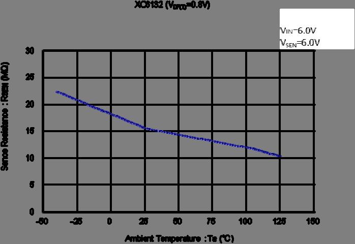
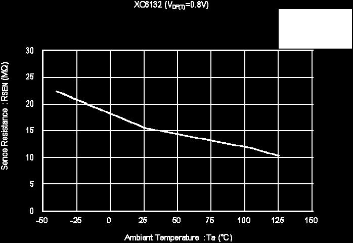
21 XC6132 Series TYPICAL PERFORMANCE CHARACTERISTICS (Continued) (5) Sense Resistance vs Ambient Temperature (6) Delay Resistance vs Ambient Temperature 21/30


22 TYPICAL PERFORMANCE CHARACTERISTICS (Continued) (7) Delay Time vs Ambient Temperature (8) Hysteresis Output Current vs Ambient Temperature (9) Hysteresis Output Current vs Input Voltage (10) Hysteresis Output Leakage Current vs Ambient Temperature (11) Output Current vs Ambient Temperature 22/30


23 XC6132 Series TYPICAL PERFORMANCE CHARACTERISTICS (Continued) (11) Output Current vs Ambient Temperature (Continued) (12) Output Current vs Input Voltage (13) Output Leakage Current vs Ambient Temperature (14) Cd Pin Sink Current vs Ambient Temperature (15) Cd Pin Sink Current vs Input Voltage 23/30

 (16)")


")

24 TYPICAL PERFORMANCE CHARACTERISTICS (Continued) (16) Cd Pin Threshold Voltage vs Ambient Temperature (17) MRB High Level Threshold Voltage vs Ambient Temperature (18) MRB Low Level Threshold Voltage vs Ambient Temperature 24/30
25 XC6132 Series PACKAGING INFORMATION SOT-26 (unit:mm) ± (0.95) (0.95) ± SOT-26 Reference Pattern Layout (unit:mm) ~ ± MAX 0.2MIN /30
26 PACKAGING INFORMATION (Continued) USP-6C (unit:mm) USP-6C Reference Pattern Layout (unit:mm) USP-6C Reference Metal Mask Design 26/30
27 XC6132 Series PACKAGING INFORMATION (Continued) SOT-26 Power Dissipation Toprmax+125 (40mm x 40mm Standard board) Power dissipation data for the SOT-26 is shown in this page. The value of power dissipation varies with the mount board conditions. Please use this data as the reference data taken in the following condition. 1. Measurement Condition Condition: Mount on a board Ambient: Natural convection Soldering: Lead (Pb) free Board: Dimensions 40 x 40 mm (1600 mm2 in one side) Copper (Cu) traces occupy 50% of the board area In top and back faces Package heat-sink is tied to the copper traces Material: Glass Epoxy (FR-4) Thickness: 1.6mm Through-hole: 4 x 0.8 Diameter Power Dissipation vs. Ambient Temperature Evaluation Board (Unit:mm) Board Mount (Tj max = 125 ) Ambient Temperature( ) Power Dissipation Pd(mW) Thermal Resistance ( /W) Pd vs. Ta 700 Power Dissipation Pd (mw) Ambient Temperature Ta ( ) 27/30
28 PACKAGING INFORMATION (Continued) USP-6C Power Dissipation (JEDEC board) Power dissipation data for the USP-6C is shown in this page. The value of power dissipation varies with the mount board conditions. Please use this data as one of reference data taken in the described condition. 1. Measurement Condition (Reference data) Condition : Mount on a board Ambient : Natural convection Soldering : Lead (Pb) free Board : The board using 4 copper layer. (76.2mm 114.3mm Area: about 8700mm 2 ) 1st layer : No copper foil (Signal layer) 2nd layer : 70mm 70mm_Connected to heat-sink. 3rd layer : 70mm 70mm_Connected to heat-sink. 4th layer : No copper foil (Signal layer) Material : Glass Epoxy(FR-4) Thickness : 1.6mm Through-hole : φ0.2mm x 60pcs Power Dissipation vs. Ambient temperature Evaluation Board (Unit:mm) Board Mount(Tjmax = 125 ) AmbientTemperature( ) PowerDissipation Pd(mW) θja( /W) Pd-Ta Power DissipationPd(mW) Ta( ) 28/30
29 XC6132 Series MARKING RULE SOT-26 USP-6C represents products series MARK X PRODUCT SERIES XC6132******-G 2,3 represents internal sequential number 01,,09, 10,, 99, A0,, A9, B0,, B9,, Z9 repeated. (G, I, J, O, Q, W excluded) 4,5 represents production lot number 01~09, 0A~0Z, 11~9Z, A1~A9, AA~AZ, B1~ZZ in order. (G, I, J, O, Q, W excluded) * No character inversion used. 29/30
30 1. The product and product specifications contained herein are subject to change without notice to improve performance characteristics. Consult us, or our representatives before use, to confirm that the information in this datasheet is up to date. 2. The information in this datasheet is intended to illustrate the operation and characteristics of our products. We neither make warranties or representations with respect to the accuracy or completeness of the information contained in this datasheet nor grant any license to any intellectual property rights of ours or any third party concerning with the information in this datasheet. 3. Applicable export control laws and regulations should be complied and the procedures required by such laws and regulations should also be followed, when the product or any information contained in this datasheet is exported. 4. The product is neither intended nor warranted for use in equipment of systems which require extremely high levels of quality and/or reliability and/or a malfunction or failure which may cause loss of human life, bodily injury, serious property damage including but not limited to devices or equipment used in 1) nuclear facilities, 2) aerospace industry, 3) medical facilities, 4) automobile industry and other transportation industry and 5) safety devices and safety equipment to control combustions and explosions. Do not use the product for the above use unless agreed by us in writing in advance. 5. Although we make continuous efforts to improve the quality and reliability of our products; nevertheless Semiconductors are likely to fail with a certain probability. So in order to prevent personal injury and/or property damage resulting from such failure, customers are required to incorporate adequate safety measures in their designs, such as system fail safes, redundancy and fire prevention features. 6. Our products are not designed to be Radiation-resistant. 7. Please use the product listed in this datasheet within the specified ranges. 8. We assume no responsibility for damage or loss due to abnormal use. 9. All rights reserved. No part of this datasheet may be copied or reproduced unless agreed by Torex Semiconductor Ltd in writing in advance. TOREX SEMICONDUCTOR LTD. 30/30
XC6134 Series ETR
 Series ETR02029-001 Delay capacitor adjustable voltage detectors with sense pin isolation and external adjustment GENERAL DESCRIPTION The series are ultra-small delay capacitor adjustable type voltage
XC6192 Series. FEATURES Input Voltage Range : 2.5V~6.0V Stand-by Current : 0.01μA (Typ.) / Turn-Off state Quiescent Current Output Current
 / Turn-Off state Quiescent Current Output Current") ETR33010-001 Power saving Push Button Load switch GENERAL DESCRIPTION The XC6192 series are power saving push button load switch ICs that shut down (shut OFF) the power line after shipping testing of battery-equipped
ETR33010-001 Power saving Push Button Load switch GENERAL DESCRIPTION The XC6192 series are power saving push button load switch ICs that shut down (shut OFF) the power line after shipping testing of battery-equipped
XBP4SMAJ Series APPLICATIONS FEATURES PIN CONFIGRATION MARKING ABSOLUTE MAXIMUM RATINGS. 400W Transient Voltage Suppressor (TVS) 1/5.
 1/5.") ETR29017-001 400W Transient Voltage Suppressor (TVS) FEATURES Bidirectional, Unidirectional, One Line Package : SMA-PG Environmentally Friendly : EU RoHS Compliant APPLICATIONS Lighting Telecommunication
ETR29017-001 400W Transient Voltage Suppressor (TVS) FEATURES Bidirectional, Unidirectional, One Line Package : SMA-PG Environmentally Friendly : EU RoHS Compliant APPLICATIONS Lighting Telecommunication
Specification. Ultra-Small Package High-Precision Voltage Detectors. Description. Features. Ordering Information. Applications.
 Description The U61Cxx series is a series of high-precision voltage detectors developed using CMOS process. The detection voltage is fixed internally with an accuracy of ±2.0%. Two output forms, Nch open-drain
R5108G SERIES. Microprocessor Supervisory Circuit with SENSE pin OUTLINE FEATURES APPLICATIONS NO.EA
 SERIES Microprocessor Supervisory Circuit with SENSE pin OUTLINE The R5108G is a microprocessor supervisory circuit and has high accuracy and ultra low supply current voltage detector with built-in delay
Monolithic Linear IC Separately-Excited Step-Down Switching Regulator (Variable Type)
") Ordering number : ENA0717C Overview The is a separately-excited step-down switching regulator (variable type). Functions High efficiency. Time-base generator (300kHz) incorporated. Current limiter incorporated.
Ordering number : ENA0717C Overview The is a separately-excited step-down switching regulator (variable type). Functions High efficiency. Time-base generator (300kHz) incorporated. Current limiter incorporated.
SII Semiconductor Corporation, Rev.2.2_01
 www.sii-ic.com TEMPERATURE SWITCH IC (THERMOSTAT IC) SII Semiconductor Corporation, 2009-2015 Rev.2.2_01 The is a temperature switch IC (thermostat IC) which detects the temperature with a temperature
Designator Description Symbol Description CMOS output Output Configuration N-ch open drain output
 Voltage Detectors With Delay Circuit Built-In LN61F General Description The LN61F is a micro-power voltage detector supervising the power supply voltage level for microprocessors or digital systems, which
Parameter Symbol Conditions Ratings Unit
 Ordering number : EN397F LB136M Monolithic Digital IC Low-Saturation Bidirectional Motor Driver for Low-Voltage Drive Overview The LB136M is a low-saturation two-channel bidirectional motor driver IC for
S-5840B Series TEMPERATURE SWITCH IC (THERMOSTAT IC) WITH LATCH. Features. Applications. Package.
 WITH LATCH. Features. Applications. Package.") www.sii-ic.com TEMPERATURE SWITCH IC (THERMOSTAT IC) WITH LATCH SII Semiconductor Corporation, 2007-2012 Rev.2.1_01 The is a temperature switch IC (thermostat IC) with a latch function which detects the
www.sii-ic.com TEMPERATURE SWITCH IC (THERMOSTAT IC) WITH LATCH SII Semiconductor Corporation, 2007-2012 Rev.2.1_01 The is a temperature switch IC (thermostat IC) with a latch function which detects the
High-Current/Overvoltage Protection Switch IC with Voltage Suppressor
 Series High-Current/Overvoltage Protection Switch IC with Voltage Suppressor OUTLINE The R5560Z is a CMOS-based high-current and overvoltage protection switch IC with voltage suppressor that uses an NMOS
Overview The LV51131T is a protection IC for 2-cell lithium-ion secondary batteries.
 Ordering number : ENA1152A LV51131T CMOS IC 2Cell LithiumIon Secondary Battery Protection IC Overview The LV51131T is a protection IC for 2cell lithiumion secondary batteries. Features Monitoring function
1-Cell Li-ion Battery Protection IC with High-accuracy Overcharge Protection
 Series 1-Cell Li-ion Battery Protection IC with High-accuracy Overcharge Protection OUTLINE The R5443Z is a one-cell Li-ion / polymer battery protection IC provides overcharge, overdischarge, and discharge
TCK22xxxG, TCK2065G, TCK1024G
 TOSHIBA CMOS Linear Integrated Circuit Silicon Monolithic TCK22xxxG, TCK2065G, TCK1024G Load Switch IC with Over current limited function The TCK22xxxG, TCK2065G and TCK1024G are Load Switch ICs for power
High-side Power Distribution Switch NCT3521U
 High-side Power Distribution Switch NCT3521U -Table of Content- 1. GENERAL DESCRIPTION...1 2. FEATURES...1 3. APPLICATIONS...2 4. PIN CONFIGURATION AND DESCRIPTION...2 5. TYPICAL APPLICATION CIRCUIT...3
Pd max2 * Mounted on a board. 800 mw Operating temperature Topr -40 to +85 C Storage temperature Tstg -55 to +150 C
 Ordering number : ENA927 LB13JM Monolithic Digital IC Low-Saturation Bidirectional Motor Driver for Low-Voltage Drive Overview The LB13JM is a low-saturation two-channel bidirectional motor driver IC for
TOSHIBA Zener Diode Silicon Epitaxial Type. CRY62 to CRZ39
 TOSHIBA Zener Diode Silicon Epitaxial Type CRY62 to CRZ39 Surge absorber Unit: mm Average power dissipation : P = 0.7 W Zener voltage : VZ = 6.2 to 39 V Suitable for compact assembly due to small surface-mount
RP173x SERIES. 11V Input 150mA LDO OUTLINE FEATURES APPLICATIONS NO.EA
 SERIES 11V Input 15mA LDO NO.EA-256-1132 OUTLINE The RP173x Series are CMOS-based voltage regulator ICs featuring 15 ma output and low supply current of Typ.2.μA. Each of these ICs consists of a voltage
A4805 SUPERVISOR (RESET IC) HIGH VOLTAGE HIGH PRECISION VOLTAGE DETECTOR
 HIGH VOLTAGE HIGH PRECISION VOLTAGE DETECTOR") DESCRIPTION The is a series of high voltage high-precision voltage detectors developed using standard CMOS process. The detection voltage is fixed internally with an accuracy of ±2.4% Nch open-drain. Low
DESCRIPTION The is a series of high voltage high-precision voltage detectors developed using standard CMOS process. The detection voltage is fixed internally with an accuracy of ±2.4% Nch open-drain. Low
Low VD with Individual SENSE Pin and Delay Function for Automotive Applications
 Series Low VD with Individual SENSE Pin and Delay Function for Automotive Applications OUTLINE The R3118x is a CMOS-based voltage detector IC with individual sense pin, high detector threshold accuracy
Bi-CMOS LSI PC and Server Fan Motor Driver
 Ordering number : ENA1748A Overview The is a motor driver for PC and server fans. Feature Direct PWM three-phsae sensorless motor driver Specifications Absolute Maximum Ratings at Ta = 25 C Bi-CMOS LSI
Features. Description. Applications. Block Diagram PT7M3808. Fixed Voltage Diagram. Adjustable Voltage Diagram(PT7M3808G01)
") Features Description Power-On Reset Generator with Adjustable Delay Time: 1.25ms to 10s. Very Low Quiescent Current: 2.8µA Typical High Threshold Accuracy: 0.5% Typ. Fixed Threshold Voltages for Standard
Features Description Power-On Reset Generator with Adjustable Delay Time: 1.25ms to 10s. Very Low Quiescent Current: 2.8µA Typical High Threshold Accuracy: 0.5% Typ. Fixed Threshold Voltages for Standard
LC75700T. Key Scan IC. Package Dimensions. Overview. Features CMOS IC
 Ordering number : ENN7632 CMOS IC LC75700T Key Scan IC Overview The LC75700T is a key scanning LSI that accepts input from up to 30 keys and can control up to four generalpurpose output ports. Therefore
TD62384APG,TD62384AFG TD62385APG,TD62385AFG
 TOSHIBA BIPOLAR DIGITAL INTEGRATED CIRCUIT SILICON MONOLITHIC TD62384APG,TD62384AFG TD62385APG,TD62385AFG 8CH LOW INPUT ACTIVE DARLINGTON SINK DRIVER The TD62384APG / AFG and TD62385APG / AFG are non inverting
System Reset IC with delay Monolithic IC PST89XB Series
 System Reset IC with delay Monolithic IC 89XB Series Outline This IC is a reset IC for turning on/off power supply and power flicker in CPU or logic systems. This IC can change delay time by an external
200 ma 36 V Input Ultra Low Supply Current VR for Automotive Applications
 Series AEC-Q1 Grade 1 Compliant 2 ma 36 V Input Ultra Low Supply Current VR for Automotive Applications OUTLINE The R1524x is a CMOS-based ultra low supply current voltage regulator featuring 2 ma output
Maintenance/ Discontinued
 ICs for Information Equipment AN8612NSB SCSI active terminator IC Overview The AN8612NSB is a terminator IC conformed to standard interface specification (SCSI-I/II) for personal computers, workstations
SII Semiconductor Corporation, Rev.2.1_00
 www.sii-ic.com 105 C OPERATION, 3.8 μa CURRENT CONSUMPTION WATCHDOG TIMER WITH RESET FUNCTION SII Semiconductor Corporation, 2015-2017 The is a watchdog timer developed using CMOS technology, which can
APX803/D 3-PIN MICROPROCESSOR RESET CIRCUIT. Description. Pin Assignments. Features. Applications APX803. ( Top View ) SOT23. ( Top View ) SOT23R GND
 SOT23. ( Top View ) SOT23R GND") /D Description Pin Assignments The /D is used for microprocessor (µp) supervisory circuits to monitor the power supplies in µp and digital ( Top View ) systems. They provide excellent circuit reliability
/D Description Pin Assignments The /D is used for microprocessor (µp) supervisory circuits to monitor the power supplies in µp and digital ( Top View ) systems. They provide excellent circuit reliability
BAT42W/BAT43W SURFACE MOUNT SCHOTTKY BARRIER DIODE
 Features: Low Turn-on Voltage Fast Switching PN Junction Guard Ring Transient and ESD Protection Designed for Surface Mount Application Plastic Material UL Recognition Flammability Classification 94V-O
LB1668, 1668M, LB1667, 1667M
 Ordering number : ENN4944A Monolithic Digital IC LB1668, 1668M, LB1667, 1667M Two-Phase Unipolar Drive Brushless Motor Drivers Overview The LB1668 Series are 2-phase unipolar drive brushless motor drivers
System Reset IC with delay Monolithic IC PST89XA Series
 System Reset IC with delay Monolithic IC 89XA Series Outline This IC is a reset IC for turning on/off power supply and power flicker in CPU or logic systems. This IC can change delay time by an external
Packaging 1. Cathode 2. Anode V Zener operating resistance. 120 Reverse current IR VR = 1 V
 Established : -3- Revised : 3-5-8 Doc No. TT4-EA-35 Silicon epitaxial planar type For constant voltage / For surge absorption circuit DZ43 in Mini type package.6 Unit: mm.3 Features Excellent rising characteristics
VCC -0.3 ~ 7 V. Maximum input voltage CP, CN, SHD, VOUT -0.3 ~ 7 V Power dissipation Pd 675 (*1) mw Operating temperature range
 mw Operating temperature range") 1/4 Structure Function Product Silicon Monolithic Integrated Circuit Voltage Regulated Charge Pump IC BU90030G Function - Input voltage range 2.0V~4.0V - PFM operation - Output voltage 4.0V (typ) - 1.5MHz(typ)
1/4 Structure Function Product Silicon Monolithic Integrated Circuit Voltage Regulated Charge Pump IC BU90030G Function - Input voltage range 2.0V~4.0V - PFM operation - Output voltage 4.0V (typ) - 1.5MHz(typ)
TOSHIBA Schottky Barrier Rectifier Schottky Barrier Type CMS05
 CMS5 TOSHIBA Schottky Barrier Rectifier Schottky Barrier Type CMS5 Switching Mode Power Supply Applications Portable Equipment Battery Applications Unit: mm Repetitive peak reverse voltage : V RRM = 3
CRY62~CRZ47 CRY62~CRZ47. Applications: Communication, Control and Measurement Equipment Constant Voltage Regulation Transient Suppressors
 TOSHIBA Zener Diode Silicon Epitaxial Type CRY62~CRZ47 Applications: Communication, Control and Equipment Constant Regulation Transient Suppressors Unit: mm Average power dissipation: P = 0.7 W Zener voltage:
1Z6.2~1Z390, 1Z6.8A~1Z30A
 TOSHIBA ZENER DIODE SILICON DIFFUSED JUNCTION TYPE 1Z6.2~1Z390, 1Z6.8A~A CONSTANT REGULATION TRANSIENT SUPPRESSORS Unit: mm Average Power Dissipation : P = 1 W Peak Reverse Power Dissipation : P RSM =
TD62M8600FG TD62M8600FG 8CH LOW SATURATION VOLTAGE SOURCE DRIVER FEATURES SCHEMATICS PIN CONNECTION (TOP VIEW)
") TOSHIBA BIPOLAR DIGITAL INTEGRATED CIRCUIT MULTI CHIP TD62M8600FG TD62M8600FG 8CH LOW SATURATION VOLTAGE SOURCE DRIVER TD62M8600FG is Multi Chip IC incorporates 8 low saturation discrete transistors equipped
TOSHIBA BIPOLAR DIGITAL INTEGRATED CIRCUIT MULTI CHIP TD62M8600FG TD62M8600FG 8CH LOW SATURATION VOLTAGE SOURCE DRIVER TD62M8600FG is Multi Chip IC incorporates 8 low saturation discrete transistors equipped
DZ5X120D0R Silicon epitaxial planar type
 Silicon epitaxial planar type For surge absorption circuit 2.9.3 Unit: mm.3 Features Excellent rising characteristics of Zener current Iz Low zener operating resistance Rz Halogen-free / RoHS compliant
TOSHIBA Schottky Barrier Diode CMS16
 CMS6 TOSHIBA Schottky Barrier Diode CMS6 Switching Mode Power Supply Applications Portable Equipment Battery Applications - Converter Applications Unit: mm Repetitive peak reverse voltage : VRRM = 4 V
20 Zener rise operating resistance RZK IZ = 0.5 ma. 60 Reverse current. 0.1 A Temperature coefficient of zener voltage *3 SZ IZ = 5 ma IR VR = 4 V
 Established : 009--09 Revised : 03-07- Doc No. TT4-EA-78 Silicon epitaxial planar type For constant voltage / For surge absorption circuit DZJ068 in SSMini type package Features Excellent rising characteristics
TBD62183A Series Usage considerations
 TBD62183A Series Usage considerations 2016 Toshiba Corporation 1 Function of transistor array There are various kinds of transistor arrays depending on their functions. Input active level There are two
4-Channel 1-wire Dimming LED Driver with Ultra Low Dropout Current Source
 4-Channel 1-wire Dimming LED Driver with Ultra Low Dropout Current Source FEATURES DESCRITION Ultra low dropout: 50mV/20mA(typical) Support up to 4 LEDs LED sink current up to 20mA ±1% LED current matching(typical)
TD62783APG, TD62783AFWG
 TOSHIBA BIPOLAR DIGITAL INTEGRATED CIRCUIT SILICON MONOLITHIC 8CH HIGH VOLTAGE SOURCE DRIVER TD62783APG, TD62783AFWG The TD62783APG / AFWG are comprised of eight source current Transistor Array. These
LB1846MC APPLICATION NOTE LB1846MC. SANYO Semiconductors
 1. (1.) 0. 6.2 SANYO Semiconductors APPLICATION NOTE Bi-CMOS integrated circuit V Low Saturation Voltage Drive Stepping Motor Driver Overview The is a 1-channel low saturation voltage stepping motor driver
SOD-723 Electrostatic discharge *2 ESD ±30 kv Junction temperature Tj 150 C
 Established : 0-0-3 Revised : 03--0 Doc No. TT4-EA-4067 Silicon epitaxial planar type For ESD protection DES06 in SSSMini type package 0.6 Unit: mm 0.3 Features High ESD Halogen-free / RoHS compliant (EU
TD62382AP,TD62382AF TD62382AP/AF 8CH LOW INPUT ACTIVE SINK DRIVER FEATURES PIN CONNECTION (TOP VIEW) SCHEMATICS (EACH DRIVER)
 SCHEMATICS (EACH DRIVER)") TOSHIBA BIPOLAR DIGITAL INTEGRATED CIRCUIT SILICON MONOLITHIC TD62382AP,TD62382AF TD62382AP/AF 8CH LOW INPUT ACTIVE SINK DRIVER The TD62382AP / AF are non inverting transistor array which are comprised
TOSHIBA BIPOLAR DIGITAL INTEGRATED CIRCUIT SILICON MONOLITHIC TD62382AP,TD62382AF TD62382AP/AF 8CH LOW INPUT ACTIVE SINK DRIVER The TD62382AP / AF are non inverting transistor array which are comprised
300 Zener rise operating resistance RZK IZ = 0.5 ma. 300 Reverse current A Temperature coefficient of zener voltage *3 SZ IZ = 2 ma
 Silicon epitaxial planar type For constant voltage / For surge absorption circuit DZJ390 in SSMini type package Features Excellent rising characteristics of zener current Iz Low zener operating resistance
TBD62785APG, TBD62785AFWG
 TOSHIBA BiCD Integrated Circuit Silicon Monolithic TBD62785APG, TBD62785AFWG 8-ch low active source type DMOS transistor array TBD62785APG/FWG TBD62785A series product is a DMOS transistor array with 8
DZ4J036K0R Silicon epitaxial planar type
 Established : 2009-2-2 Revised : 20-0-0 Doc No. TT-EA-2026 Silicon epitaxial planar type For constant voltage / For surge absorption circuit 2.0 0. Unit: mm 0. Features Excellent rising characteristics
1.0 V Zener voltage *1, *2 VZ IZ = 5 ma Zener operating resistance RZ IZ = 5 ma. 40 Zener rise operating resistance RZK IZ = 0.
 Established : 9--4 Revised : 3-7- Doc No. TT4-EA-557 DZJ5 L Silicon epitaxial planar type For constant voltage / For surge absorption circuit.5.35 DZJ5 L Unit: mm.3 Features Excellent rising characteristics
Li-ION/POLYMER 1CELL PROTECTOR R5480 SERIES. Outline. Preliminary_
 Li-ION/POLYMER 1CELL PROTECTOR R5480 SERIES NO. EA-308-130709 Outline The R5480 is a high voltage tolerance CMOS-based protection IC for over-charge/discharge and over-current of rechargeable one-cell
DZ L Silicon epitaxial planar type
 Established : -9-9 Revised : 3-5-8 Doc No. TT4-EA-378 DZ456L DZ456L Silicon epitaxial planar type For constant voltage / For surge absorption circuit Capability of withstanding a high surge type DZW56
SII Semiconductor Corporation, 2015 Rev.1.0_01
 www.sii-ic.com S-35720 Series FOR AUTOMOTIVE 125 C OPERATION WITH INTERRUPT TIME SETTING PIN CONVENIENCE TIMER SII Semiconductor Corporation, 2015 Rev.1.0_01 The convenience timer is a CMOS timer IC which
Low cost, 3 Step Dimming Control, Linear AC LED Driver. Features. Applications. Fig. 1 Typical application with 3 Step dimming
 Low cost, 3 Step Dimming Control, Linear AC LED Driver General Description The is a non-isolated linear LED driver for general purpose LED lighting applications. It is capable of driving LEDs in multiple
Old Company Name in Catalogs and Other Documents
 To our customers, Old Company Name in Catalogs and Other Documents On April 1 st, 2010, NEC Electronics Corporation merged with Renesas Technology Corporation, and Renesas Electronics Corporation took
Li-ION/POLYMER 1CELL PROTECTOR R5486 SERIES Outline
 Li-ION/POLYMER 1CELL PROTECTOR R5486 SERIES 20140801 NO. EA-339-140801 Outline The R5486 is a high voltage tolerance CMOS-based protection IC for over-charge/discharge and over-current of rechargeable
S-8880A Series ENERGY HARVESTING POWERED BY ULTRA-LOW POWER AND ULTRA-LOW VOLTAGE OPERATION BOOST CHARGE PUMP FOR STEP-UP DC-DC CONVERTER STARTUP
 www.ablicinc.com ENERGY HARVESTING POWERED BY ULTRA-LOW POWER AND ULTRA-LOW VOLTAGE OPERATION BOOST CHARGE PUMP FOR STEP-UP DC-DC CONVERTER STARTUP ABLIC Inc., 2017 The is a boost charge pump for step-up
Maximum Power Dissipation 0.67W Operating Temperature Range 40 C to 85 C Storage Temperature Range 55 C to 150 C
 Description The ACE345E is a load switch which provides full protection to systems and loads which may encounter large current conditions. ACE345E offers a 95mΩ current-limited switch which can operate
MIC2544A/2548A. General Description. Features. Applications. Typical Application. Programmable Current Limit High-Side Switch
 Programmable Current Limit High-Side Switch General Description The MIC2544A and MIC2548A are integrated, high-side power switches optimized for low loss DC power switching and other power management applications,
MIC826. General Description. Features. Applications. Typical Application
 Voltage Supervisor with Watchdog Timer, Manual Reset, and Dual Outputs In 1.6mm x 1.6mm TDFN General Description The is a low-current, ultra-small, voltage supervisor with manual reset input, watchdog
DZ2S180C0L Silicon epitaxial planar type
 Established : -5-7 Revised : 3-7- Doc No. TT-EA-597 DZS8CL DZS8CL Silicon epitaxial planar type For ESD protection Bi-directional type.8 Unit: mm.3 Features High ESD Low terminal capacitance Ct Halogen-free
AOZ8101. Ultra-Low Capacitance TVS Diode Array. General Description. Features. Applications. Typical Application
 Ultra-Low Capacitance TS Diode Array General Description The AOZ8101 is a transient voltage suppressor array designed to protect high speed data lines from Electro Static Discharge (ESD) and lightning.
WS4601 WS4601. Descriptions. Features. Applications. Order information. 80mΩ, Current Limited, Power Distribution Switch
 80mΩ, Current Limited, Power Distribution Switch www.sh-willsemi.com Descriptions The is high-side switch with ultra-low ON resistance P-MOSFET. Integrated current-limit function can limit inrush current
LC75808E, 75808W. 1/8 to 1/10 Duty LCD Display Drivers with Key Input Function
 Ordering number : ENN6370A CMOS IC LC75808E, 75808W 1/8 to 1/10 Duty LCD Display Drivers with Key Input Function Overview The LC75808E and LC75808W are 1/8 to 1/10 duty LCD display drivers that can directly
ABLIC Inc., Rev.1.4_00
 www.ablicinc.com S-35720 Series FOR AUTOMOTIVE 125 C OPERATION WITH INTERRUPT TIME SETTING PIN CONVENIENCE TIMER ABLIC Inc., 2015-2018 Rev.1.4_00 The convenience timer is a CMOS timer IC which operates
DATA SHEET ZENER DIODES 1.0 W PLANAR TYPE 2-PIN SMALL POWER MINI MOLD. Parameter Symbol Ratings Unit Remarks
 DATA SHEET ZENER DIODES RD2.0FS to RD20FS ZENER DIODES.0 W PLANAR TYPE 2-PIN SMALL POWER MINI MOLD DESCRIPTION Type RD2.0FS to RD20FS series are 2-pin small power mini mold package Zener diodes possessing
AOZ8900. Ultra-Low Capacitance TVS Diode Array PRELIMINARY. Features. General Description. Applications. Typical Application
 Ultra-Low Capacitance TS Diode Array General Description The is a transient voltage suppressor array designed to protect high speed data lines from Electro Static Discharge (ESD) and lightning. This device
SRV05-4A. Green Products. Description. Features. China - Germany - Korea - Singapore - United States - smc-diodes.
 Description The SRV05-4A is a low capacitance TVS (Transient Voltage Suppressor) array designed to protect sensitive semiconductor components from electrical overstress when interfaced to high-speed data
TBD62384A series Usage considerations
 TBD62384A series Usage considerations 8ch-low active sink type DMOS transistor array for level shift circuits and LEDs. TBD62384A series are low active and non-built-in clamp diode version of TBD62083A
Single-Phase 6.0A Glass Passivated Bridge Rectifier
 0 Single-Phase 6.0A Glass Passivated Bridge Rectifier 0 Features D3K Glass passivated die construction Low forward voltage drop High current capability High surge current capability Designed for surface
PT7M Ultra Low Voltage Detectors
 Features Factory-Set Reset Threshold Voltages for Nominal Supplies from 1.2V to 1.8V Low power consumption : Typ 7.5μA Five different timeout periods available: 70μs(voltage detector), 1.5ms, 30ms, 210ms
TOSHIBA CMOS Digital Integrated Circuit Silicon Monolithic TC7SGU04FU IN A GND
 TOSHIBA CMOS Digital Integrated Circuit Silicon Monolithic TC7SGU04FU Inverter (Unbuffered) Features High output current : ±8 ma (min) at = 3 Super high speed operation : t pd = 1.9 ns (typ.) at = 3.3,
Maintenance/ Discontinued
 Zener Diodes Silicon planar type For stabilization of power supply Features Extremely low noise voltage caused from the diode (2.4 V to 39V, /3 to /0 of our conventional MAZ3xxx series) Extremely good
TCS40DPR. Digital Output Magnetic Sensor. Feature. Marking Pin Assignment (Top View) Function Table PA8
 Function Table PA8") TOSHIBA CMOS Digital Integrated Circuit Silicon Monolithic TCS40DPR Digital Output Magnetic Sensor Feature Push-Pull Output South-Pole and North-Pole Detection Weight: 11.0 mg (typ.) SON3-P-0203-1.90S
TOSHIBA CMOS Digital Integrated Circuit Silicon Monolithic TCS40DPR Digital Output Magnetic Sensor Feature Push-Pull Output South-Pole and North-Pole Detection Weight: 11.0 mg (typ.) SON3-P-0203-1.90S
TBD62781A series Usage considerations
 TBD62781A series Usage considerations 8ch-high active source type DMOS transistor array for level shift circuits and LEDs. TBD62781A series has an internal pull-down resistor, which is not incorporated
RN1101MFV,RN1102MFV,RN1103MFV RN1104MFV,RN1105MFV,RN1106MFV
 TOSHIBA Transistor Silicon NPN Epitaxial Type (PCT Process),,,, Switching, Inverter Circuit, Interface Circuit and Driver Circuit Applications z Ultra-small package, suited to very high density mounting
IC for CMOS System Reset Monolithic IC PST81XX, 82XX Series
 IC for CMOS System Reset 8XX, 8XX Series IC for CMOS System Reset Monolithic IC 8XX, 8XX Series Outline This IC functions in a variety of CPU systems and other logic systems, to detect supply voltage and
Old Company Name in Catalogs and Other Documents
 To our customers, Old Company Name in Catalogs and Other Documents On April 1 st, 2010, NEC Electronics Corporation merged with Renesas Technology Corporation, and Renesas Electronics Corporation took
S-8215A Series BATTERY PROTECTION IC FOR 3-SERIAL TO 5-SERIAL CELL PACK (SECONDARY PROTECTION) Features. Application. Packages.
 Features. Application. Packages.") www.ablicinc.com BATTERY PROTECTION IC FOR 3-SERIAL TO 5-SERIAL CELL PACK (SECONDARY PROTECTION) ABLIC Inc., 2010-2017 The is used for secondary protection of lithium-ion rechargeable batteries, and incorporates
www.ablicinc.com BATTERY PROTECTION IC FOR 3-SERIAL TO 5-SERIAL CELL PACK (SECONDARY PROTECTION) ABLIC Inc., 2010-2017 The is used for secondary protection of lithium-ion rechargeable batteries, and incorporates
ZENER DIODES RD2.0S to RD150S
 DATA SHEET ZENER DIODES RD2.0S to RD150S ZENER DIODES 200 mw 2-PIN SUPER MINI MOLD DESCRIPTION Type RD2.0S to RD150S series are 2 pin super mini mold package zener diodes possessing an allowable power
HZM6.8WA. Silicon Epitaxial Planar Zener Diode for Surge Absorb. ADE A(Z) Rev 1 Feb. 1, Features. Ordering Information.
 Rev 1 Feb. 1, Features. Ordering Information.") Silicon Epitaxial Planar Zener Diode for Surge Absorb Features HZM6.8WA has two devices, and can absorb external + and -surge. MPAK Package is suitable for high density surface mounting and high speed
Silicon Epitaxial Planar Zener Diode for Surge Absorb Features HZM6.8WA has two devices, and can absorb external + and -surge. MPAK Package is suitable for high density surface mounting and high speed
Old Company Name in Catalogs and Other Documents
 To our customers, Old Company Name in Catalogs and Other Documents On April st, 00, NEC Electronics Corporation merged with Renesas Technology Corporation, and Renesas Electronics Corporation took over
MIC2546/2547. Features. General Description. Applications. Typical Application. Dual Programable Current Limit Switch
 Dual Programable Current Limit Switch General Description The MIC2546 and MIC2547 are integrated high-side dual power switches optimized for low loss dc power switching and other power management applications,
TOSHIBA Bi-CMOS Integrated Circuit Silicon Monolithic TB62781FNG
 TOSHIBA Bi-CMOS Integrated Circuit Silicon Monolithic TB62781FNG 9-Channel Current LED Driver of the 3.3V and 5V Power Supply Voltage Operation 1. Features Power supply voltages: V CC = 3.3 V/5 V Output
TBD62387A series Usage considerations
 TBD62387A series Usage considerations 8ch-low active sink type DMOS transistor array for level shift circuits, inductive loads such as motors and relays, and LEDs. TBD62387A series are low active version
CRY62~CRZ47 CRY62~CRZ47. Use in Communication, Automation and Measurement Equipment Constant Voltage Regulation Transient Suppressors
 TOSHIBA Zener Diode Silicon Epitaxial Type CRY62~CRZ47 Use in Communication, Automation and Equipment Constant Regulation Transient Suppressors Unit: mm Average power dissipation: P = 0.7 W Zener voltage:
ZSPM4121. Under-Voltage Load Switch for Smart Battery Management. Datasheet. Brief Description. Features. Related IDT Smart Power Products
 Under-Voltage Load Switch for Smart Battery Management ZSPM4121 Datasheet Brief Description The ZSPM4121 battery management load switch can be used to protect a battery from excessive discharge. It actively
A8241. AiT Semiconductor Inc. APPLICATION ORDERING INFORMATION. Low 60mV Dropout at 20mA 4% LED Current Matching
 DESCRIPTION The is a CMOS based White/Blue LED driver with stand-alone capability. The driver is primarily designed for LED backlighting of LCD display powered by Li-ion battery with its high efficiency,
BIPOLAR ANALOG INTEGRATED CIRCUIT
 DATA SHEET BIPOLAR ANALOG INTEGRATED CIRCUIT µ PC16 2.5 V HIGH PRECISION REFEREE VOLTAGE CIRCUIT DESCRIPTION The µ PC16 are high accuracy and low drift voltage references of 2.5 V output voltage. This
STBC ma standalone linear Li-Ion battery charger with thermal regulation. Description. Features. Applications
 800 ma standalone linear Li-Ion battery charger with thermal regulation Description Datasheet - production data Features Programmable charge current up to 800 ma No external MOSFET, sense resistors or
R1524x Series. 200 ma 36 V Input Ultra Low Supply Current VR OUTLINE FEATURES APPLICATIONS. No. EA
 Series 2 ma 36 V Input Ultra Low Supply Current VR OUTLINE No. EA-332-18524 The R1524x is an ultra-low supply current voltage regulator featuring 2 ma output current and 36 V input voltage. This device
ESD NOISE CLIPPING DIODE NNCD2.0DA to NNCD39DA
 DATA SHEET ESD NOISE CLIPPING DIODE NNCD2.0DA to NNCD39DA ELECTROSTATIC DISCHARGE NOISE CLIPPING DIODE 2-PIN SUPER MINI MOLD DESCRIPTION These products are the diode developed for ESD (Electrostatic Discharge)
WS3210C62 WS3210C62 Over-Voltage Protection Load Switch Descriptions CSP-9L (Bottom View) Pin Configuration (Top View)
 Pin Configuration (Top View)") Over-Voltage Protection Load Switch http://www.sh-willsemi.com Descriptions The features a low R ON internal High Voltage Switch and an input range of absolute maximum 30V. An internal input clamp is capable
Over-Voltage Protection Load Switch http://www.sh-willsemi.com Descriptions The features a low R ON internal High Voltage Switch and an input range of absolute maximum 30V. An internal input clamp is capable
LN61C. Ultra-Small Package High-Precision Voltage Detector. General Description. Applications. Features. Package. Ordering Information
 Ultra-Small Package High-Precision Voltage Detector General Description The series is a series of high-precision voltage detectors developed using CMOS process. The detection voltage is fixed internally
TBD62064A series Usage considerations
 TBD62064A series Usage considerations 2016 Toshiba Corporation 1 Function of transistor array There are various kinds of transistor arrays depending on their functions. Input active level There are two
2:1 MULTIPLEXER CHIP FOR PCI-EXPRESS ICS Features
 DATASHEET 2:1 MULTIPLEXER CHIP FOR PCI-EXPRESS ICS557-08 Description The ICS557-08 is a 2:1 multiplexer chip that allows the user to select one of the two HCSL (Host Clock Signal Level) input pairs and
RP112x SERIES. Low Noise 150mA LDO REGULATOR OUTLINE FEATURES APPLICATIONS NO.EA
 SERIES Low Noise 5mA LDO REGULATOR NO.EA-58-3 OUTLINE The RPx Series are CMOS-based voltage regulator (LDO) ICs, which have been developed using the CMOS process technology, with high output voltage accuracy,
PT V Single coil Hall Driver IC with FG output
 DC Brushless Motor PT3936 24V Single coil with FG output Applications Single coil DC brushless motor Support pre-driver application Package: SOT89-5pin P/N: PT3936-S SOT89 Features Built-in hall sensor
LA4446. Car Stereo-Use 5.5W 2-Channel AF Power Amplifier. Package Dimensions
 Ordering number:enn2636c Monolithic Linear IC LA4446 Car Stereo-Use 5.5W 2-Channel AF Power Amplifier Features Dual channels. Output : 5.5W 2 (typ.) Low pop noise at the time of power supply ON/OFF and