AQ-200 SERIES PROTECTION,CONTROL, MEASUREMENT AND MONITORING IEDS
|
|
|
- Christiana May
- 5 years ago
- Views:
Transcription


1 AQ-200 SERIES PROTECTION,CONTROL, MEASUREMENT AND MONITORING IEDS
2 CONTENTS AQ-200 series protection, control, measurement and monitoring IEDs... 3 AQ-200 benefits... 3 Arcteq Innovation: Ultra-accurate measurement technology... 4 Arcteq Innovation: Intermittent earth fault protection Arcteq Innovation: Broad range multi-criteria earth-fault protection... 6 Arcteq Innovation: Disturbance recorder and power quality... 7 Arcteq Innovation: Cable end differential protection... 8 AQ-200 protection functions... 9 AQ-200 control functions AQtivate 200 Setting and configuration software suite AQtivate PRO Substation Management Software AQ-F201 Overcurrent and earth-fault relay AQ-F205 Feeder protection relay AQ-F210 Feeder protection IED AQ-F215 Feeder protection IED AQ-F255 Feeder protection IED AQ-M210 Motor protection IED AQ-M215 Motor protection IED AQ-M255 Motor protection IED AQ-M257 Motor protection IED AQ-G215 Generator protection IED AQ-G257 Generator protection IED The Generator and motor Commander AQ-V211 Voltage protection IED AQ-T215 Voltage regulating IED AQ-T216 Transformer protection IED AQ-T256 Transformer protection IED Selection Table AQ-T257 Transformer protection IED AQ-T259 Transformer protection IED AQ-S214 Alarm and indication IED AQ-S254 Alarm and indication IED AQ-S215 Bay control IED AQ-S255 Bay control IED AQ-P215 Power monitoring IED AQ-E215 Energy managemet IED Technical data Typical wiring diagram AQ-210 installation and dimensions AQ-250 Installation and dimensions Order code... 57
3 AQ-200 SERIES PROTECTION, CONTROL, MEASUREMENT AND MONITORING IEDS The AQ-200 series provides an optimal protection and control solution for any utility, power plant, wind-power, off-shore, marine, industrial, commercial or institutional electrical protection and control applications. The AQ-200 series offers integrated or segregated protection control, monitoring, measuring solutions with powerful comp lementary monitoring, measuring, communication and diagnostics information. The AQ-200 is developed using the latest available technologies providing a totally new dimension and options to protection and control engineers. AQ-200 BENEFITS VERSATILE PROTECTION DESIGN AQ-200 series is characterized by fast, versatile and dependable protection functions with uniquely wide operating frequency band of 6 75Hz making AQ-200 perfect choice for the most demanding protection applications including rotating machines. MODULARITY Fully modular hardware construction gives a high level of flexibility; additional I/O or communication cards can be simply plugged in according to application needs. USABILITY Maximum use of the IEDs is guaranteed by features such as guided wizards, sophisticated setting aids, highly customizable HMI, file storage of pdf or other supportive documents and extensive user log information. Track down a complete user history register including setting change and other operational history. PERFORMANCE The AQ-200 series offers truly sub-cycle instantaneous triptimes. You can add a fast integrated arc protection to your traditional protection scheme. Powerful PLC programming is included for the most demanding applications allowing for extensive customization. Up to 100 disturbance records of up to 10 seconds each and events are stored in non-volatile memory. COMMUNICATION Native Ethernet communication provides for fast and seamless communication. The AQ-200 communicates using variety of standard protocols including IEC substation communication standard with fast GOOSE messaging. SAVINGS IN ENGINEERING TIME AQtivate 200 free of charge software suite saves valuable engineering time by offering an intuitive and easy to use human machine interface. Download all relay settings instantly using native 100Mb/s Ethernet connection either at IED front port or rear port through Ethernet network. STANDARDIZED HARDWARE Trouble free logistics and stocking with highly standardized hardware design. Five CT inputs with software settable secondary currents and software configurable digital input thresholds for voltage are standard features of AQ-200 series. IEC & IEEE 1588 High-availability Seamless Redundancy (HSR) support Parallel Redundancy Protocol (PRP) support Precision Time Protocol (PTP) according to IEEE


4 ARCTEQ INNOVATION Ultra-accurate measurement technology ACCURATE AND FREQUENCY INDEPENDENT Arcteq s AQ-200 series protection and control IEDs are deploying patented measurement technology. This has resulted in a very unique combination of class 0.2S power and energy measurement accuracy, full dynamic measurement range and frequency independent measurement and protection in a single device. Therefore the AQ-200 series is well applicable for any applications requiring accurate measurement alone, or combination of measurement and protection. Frequency independent measurement technology allows for more accurate rotating machine protections as well. The AQ-200 series provides an optimal protection and control solution for any utility. The frequency tracking functionality keeps the measurement accuracy in Arcteq protection relays within class 0.2S between 6 and 75 Hz frequency. PATENTED MEASUREMENT ALGORITHM The system frequency independent measurement accuracy has been achieved in AQ-200 series devices by adjusting the sample rate of the measurement channels according to the measured system frequency in a way that FFT (Fast Fourier Transformation) calculation can always make use of full power cycle buffer. Furthermore, all analog channels are calibrated against 8 system frequency points for both, magnitude and angle. This frequency dependent correction compensates the used measurement hardware frequency dependencies as the measurement hardware is not linear considering the measured analog signal frequency. Therefore the magnitude and angle measurements need to be calibrated against frequency to obtain high accuracy. Furthermore, the measured channels FFT result fundamental frequency component is corrected for magnitude and angle errors by Arcteq AQ-200 series patented calibration algorithms. The measurement accuracy in Arcteq protection relays stays within 0.2% even at extremely low currents. 4

 processing")
 combined with up to 3.2kHz sampling rate lays the foundation for accurate algorithms of fast phenomenon such as intermittent earth-fault protection.")
5 ARCTEQ INNOVATION Intermittent earth fault protection BACKGROUND Underground cabling of the distribution networks makes them less vulnerable to disturbances, but at the same time leading to higher earth fault currents. Networks are compensated with Petersen coils to keep earth fault currents on lower level. Typically an intermittent earth-fault is a millisecond self-extinguishing flash-over fault from phase to ground causing heavy transient spikes into the electric network. Traditional non-intermittent directional earth fault protection is unable to operate correctly in this type of fault since it is typically based into FFT (Fast Fourier Transformation) processing results based on fundamental frequency RMS values. ARCTEQ PATENTED SOLUTION Arcteq s breakthrough IED technology in AQ-200 series with patented very accurate measurement technology (better than 0.2% for energy and power measurement) combined with up to 3.2kHz sampling rate lays the foundation for accurate algorithms of fast phenomenon such as intermittent earth-fault protection. The algorithm makes use of the accurate measurement and sampling technology by searching for spikes in I0 and U0 generated by intermittent earth fault strike through. Algorithm is able to remove all unnecessary and confusing data and concentrate only on the spikes. By calculating the delta of raw samples using an innovative patented admittance based formula the polarity of the spikes in I0 and U0 is determined accurately distinguishing effectively a faulty feeder over healthy background feeder. The algorithms have been proven effective in extensive field tests with electrical utilities, and have been installed in networks since The AQ-F215 and AQ-F255 feeder terminal is equipped with the intermittent earth fault protection. The protection algorithm combined with 0.2S measurement class and 3.2 khz sampling frequency, enables it to detect and isolate intermittent earth faults with high accuracy. The triptime of the intermittent earth fault protection is set to 500 ms. From this disturbance record from AQ-F215 or AQ-F255 relay can be read that the relay detects the intermittent earth faults and trips within the set time. The algorithms have been proven effective in extensive field tests with electrical utilities, and have been installed in networks since
6 ARCTEQ INNOVATION Broad range multi-criteria earth-fault protection THE PROBLEM The increase of medium voltage cabling, connection of distributed generation and compensated networks (Petersen coil) along with distributed compensation has led to new challenges in earth-fault protection of distribution feeders. Challen ging combinations of short cable feeders, long overhead feeders and mixed cable and overhead network is increasing significantly among distribution system operators. Relaying on conventional protection methods may lead to either nuisance trips of healthy feeders or undetected faults in faulty feeders. When protecting compensated long-distance cables and overhead lines it is in some cases difficult to distinguish between healthy- and faulty feeder when protection is based on merely measuring the angle and magnitude of residual voltage and currents. Earth fault protection often requires information on network status (ungrounded or compensated). When changing between these two statuses setting group must be changed and especially in case of distributed compensation the change may be difficult or impossible to arrange. New broad range mode available in AQ-200 series protection and control IEDs can protect against earth-fault in both ungrounded and compensated networks without setting changes. THE SOLUTION: NEW BROAD RANGE MODE WITH MULTI-CRITERIA DETECTION New broad range mode available in AQ-200 series protection and control IEDs can protect against earth-fault in both ungrounded and compensated networks without setting changes. The algorithm reliability is further increased using a new multi - -criteria detection. This optional additional tripping condition for compensated networks uses Arcteq s patented, high-resolution intermittent earth-fault algorithm with added symmetrical compo nent calculation of phase currents and voltages. If this mode is activated the tripping criteria comprises of a measured residual current in the third or fourth quadrant and the symmetrical components of voltages and currents detecting a fault. No extra parameterization is required compared to traditional method. Multi-criteria algorithm can be tested with Comtrade files supplied by Arcteq. Function requires connection of 3-phase currents, residual current and zero sequence voltage to operate correctly. To avoid unnecessary trips due to CT errors, encroachment area in compensated long healthy feeders can be added. NEW BROAD RANGE MODE 180 Optional tripping for long challenging compensated lines, based on network changes in the initial stage of the fault. U Unearthed tripping Compensated tripping 0 Encroachment area against I0 CT error in long healthy lines Operation of new broad range mode covers both ungrounded and compensated networks and is equipped with optional additional multi-criteria detection for compensated networks to increase the protection reliability. For a complete coverage of feeder earth-faults in compensated networks, the intermittent / transient type of earth-faults are to be protected by Arcteq s patented intermittent earth-fault protection stage available in the AQ 200 series feeder protection IEDs. 6

7 ARCTEQ INNOVATION Disturbance recorder and power quality DISTURBANCE RECORDER CAPACITY The disturbance recorder in AQ 200 series IEDs is a high capacity and fully digital recorder integrated to protection relay. Maximum sample rate of the recorder analog channels is 64 samples per cycle. The recorder supports 96 digital channels simultaneously with measured 9 analog channels. Even all measured and calculated values can be registered as digital channels with 5ms sample time. This feature is useful in for instance motor start up sequence, as users can track fully sampled analogue waveform values and every 5ms sampled RMS values simultaneously. The memory capacity in AQ 200 series IEDs allows for up to 100 nonvolatile records with total of 500 second recording time with full sample rate and maximum number of recorded channels. Recorder output is in general comtrade format and it is compatible with most viewers and relay test sets. The comtrade file is based on the IEEE Std C standard. AQ 200 series disturbance recorder is a great tool for analyzing the performance of the power system in network disturbance situations. DOCUMENTING VOLTAGE SAGS AND SWELLS WITH DISTURBANCE RECORDER AQ 200 series disturbance recorder is a great tool for analyzing the performance of the power system in network disturbance situ ations. Voltage sags and swells are often monitored for power quality analyzes. The disturbance recorder can be triggered with any signal in the IED. Over -and undervoltage or any programmable protection stages can be used to trigger the recorder. With Arcteq s fast acting protection stages the voltage sags and swells of as little as 10-15ms can be recorded and documented. Example recording with high harmonic content. HARMONICS MONITORING The AQ 200 series IEDs are measuring harmonics of up to 31st order for both currents and voltages. Arcteq s innovative and unique harmonic overcurrent stages (50/50h) can be used for alarming, tripping and triggering the disturbance recorder. Freely settable harmonic overcurrent stages can monitor and act on any of the current harmonics from 2nd to 19th order. The disturbance recorder can record harmonic content up to 31st order. DISTURBANCE RECORDER SETTING EXAMPLES Samples per cycle Analogue channels Digital channels Record duration 5s 110s 60s Total number of records


8 ARCTEQ INNOVATION Cable end differential protection CABLE END FAULTS AND ARC FLASH INCIDENTS Arc flash faults within the switchgear are typically caused by reasons such as human errors, equipment failures, foreign objects, or animals in the gear or by combination of aging materials, dirt and lack of maintenance. As per empiric data, the most common non-human intruded fault location is the cable compartment, and more precisely the cable end. Degrading insulation level or faulty cable connections are the most common causes for cable end faults. Cable faults often start by a small earth-leakage developing to full single-phase faults. Further, if not detected and tripped, the single-phase faults may develop to cross country or 3-phase faults. COMPENSATED CABLE END DIFFERENTIAL PROTECTION Arcteq has developed a proactive cable end protection in its AQ- 200 series protection and control IEDs. The aim of the protection function is to provide an early detection of cable end fault. Typically cable end protection is implemented as an alarming function indicating the need of preventive maintenance. Operating principle is based on low impedance differential protection with settable bias characteristics. Differential current is calculated in between of summed phase currents and selected residual current input measured by a core balance CT. Figure 1: Cable end differential protection without natural unbalance compensation in use. Phase current CT errors are causing significant differential current. Compensation is essential to have a sensitive protection setting. The function provides natural measurement unbalance compensation to have higher operating sensitivity for monitoring cable end faults. When calculating the residual current from phase currents the natural unbalance may be in total up to 10% with CT s of class 5P. When the natural unbalance current is compensated in this same situation the differential settings may be set more sensitive and the natural unbalance does not affect into the calculation. If in the cable end should occur any starting faults the cable end differential catches the difference in between of the ingoing and outgoing residual currents and the resulting signal can be used for alarming or tripping purpose for the feeder with failing cable end. The sensitivity of the algorithm and settings can be freely user settable. THE BENEFIT Cable end differential protection uses the elements already available in the protection scheme: 3-phase CT s and residual core balance CT. There is no need for extra hardware or wiring. The sensitive compensated cable end differential protection can be used with no extra cost to provide additional switchgear and personnel safety. Figure 2: Compensated cable end differential protection during a small earth-leakage current. Due to natural unbalance compensation the function can alarm correctly even on small differential currents. 8
9 AQ-200 PROTECTION FUNCTIONS FEEDER PROTECTION ALGORITHMS NON-DIRECTIONAL AND DIRECTIONAL OVERCURRENT AND EARTH-FAULT PROTECTION (ANSI 50/51, 50/51N, 67, 67N) Up to four stages of non-directional overcurrent and earth-fault protection functions and four stages of directional overcurrent and earth-fault functions with wide setting range of xIn for overcurrent and xIn for earth-fault. Directional overcurrent decision is based on positive sequence voltage and voltage memory is used for close in faults. Definite time, IEC or ANSI inverse time curves with settable reset delays to coordinate with electromechanical relays. Instantaneous operate time is <20ms. Includes option for internal harmonic blocking (2nd and 5th harmonic). HARMONIC OVERCURRENT PROTECTION (ANSI 50/51H, 68) Configurable trip or alarm or blocking signal based on extensive harmonic content. Up to four stages based on 2nd, 3rd, 4th, 5th or 7th, 11th, 13th, 15th 17th or 19th harmonic. Definite time, IEC or ANSI inverse time curves with settable reset delays. PROGRAMMABLE STAGE PGX >/< (99) The programmable stage (PGS) is a stage that can be programmed by the user to create more advanced applications either as an individual stage or together with programmable logic. The relay has ten programmable stages, of which each can be set to compare from one to three analog measurements. The programmable stages have over-, under- and rate-of-change available with definite time delay to trip from pick-up included. CABLE AND TRANSFORMER THERMAL PROTECTION (ANSI 49L/49T) Thermal protection for cable or transformer overloading based on single (cable) or dual (transformer) time constants used for heating and cooling calculation of the thermal image. Provides maximum allowed load current, two alarm stages and tripping stage. Supports also close request inhibit. CABLE END DIFFERENTIAL PROTECTION (ANSI 87N) This protection stage can be configured either as a low impedance restricted earth-fault protection or cable end differential protection. When monitoring cable end healthy condition the function compares differential current of measured phase and core balance CT currents. Natural unbalance compensation due to CT inaccuracies is included for enabling sensitive operation. The function serves for pre-emptive arc fault protection purposes. TRANSIENT/INTERMITTENT EARTH-FAULT PROTECTION (ANSI 67NT) This sample based intermittent earth-fault algorithm makes use of AQ-200 series accurate measurement and sampling technology by searching the transient spikes in both I0 and U0 generated by intermittent earth fault strike through. Algorithm is able to remove all unnecessary and confusing data and concentrate only on the spikes. By calculating the delta of raw samples using an innovative admittance based formula the polarity of the spikes in I0 and U0 is determined accurately distinguishing effectively a faulty feeder over healthy background feeder. Freely settable function operation time guarantees simple coordination with back-up residual voltage protection. CIRCUIT BREAKER FAILURE PROTECTION (50BF/52BF) User settable function initiation based on overcurrent or digital input or digital output status alone or in any combination. Two separate levels for Re-Trip and CBFP. ARC PROTECTION (50ARC/50NARC) Optional fast arc protection is available in selected models. Stage can be set to operate on any combination of arc light, arc pressure, arc residual current or arc phase current conditions. Typical operation time is 7ms. VOLTAGE AND FREQUENCY PROTECTION ALGORITHMS VOLTAGE PROTECTION (ANSI 59/27/59N/47) Up to four under and overvoltage and residual overvoltage and positive/negative sequence voltage stages with DT or IDMT charac teristics and settable voltage thresholds. FREQUENCY PROTECTION (ANSI 81U/81O/81R) Up to eight under and overfrequency stages and eight rate of change of frequency stages with DT characteristics. May be applied for extensive load shedding logic or simple under frequency protection. 9
10 VECTOR JUMP PROTECTION (ANSI 78) The vector jump (or vector shift) protection is suitable to detect most islanding situations and switch off the mains breaker in order to let the generator supply only loads under their rated power value. The algorithm follows the samples of chosen measured voltages (64samples/cycle). Used reference voltage can be all or any phase- to phase or phase- to neutral voltages. MACHINE PROTECTION ALGORITHMS DIFFERENTIAL PROTECTION (ANSI 87T/87G/87M) Generic differential protection applicable for transformers, motors, generators or other machines requiring sensitive protection stabilized for out-zone faults. Stage features integrated 2nd and 5th harmonic blocking and predefined or custom setting of protected objects connection group. Stage verifies object nominal values and connection group settings. MOTOR AND GENERATOR THERMAL PROTECTION (ANSI 49M/49G) Highly accurate motor and generator thermal modeling based on up to total of five time constants. Stator and rotor heating and cooling time constants can be set independently according to the application. Dedicated cooling time constant may be used for running and stopped machine independently. Contribution of the stator and rotor time constant effect can be set freely. Negative phase sequence current bias setting guarantees an optimal thermal image in unbalanced conditions. Ambient temperature biasing is supported either from manually set level or reading from RTD. Thermal image function calculates and displays the estimated temperatures in percentage, Celsius or Fahrenheit for easy reading of the motor thermal capacity used. Two independent alarm levels and trip and restart inhibit levels can be set easily. starts in cold or hot situation can be set separately as well as the minimum time in between starts. If allowed amount of starts is used the function will inhibit further starts until the motor is cooled enough to allow a new starting attempt. LOSS OF LOAD PROTECTION (ANSI 37) Undercurrent based loss of load protection is typically applied for conveyor controlling motors or other applications where loss of mechanical load is possible. Instant operation may be set for the most critical applications preventing further damage in case of lost load. MECHANICAL JAM PROTECTION (ANSI 51M) Motor mechanical jam protection is activated only after the motor has started. The mechanical jam protection can be set very sensitive due to being disabled during motor start. UNBALANCE PROTECTION (ANSI 46/46R/46L) Up to four user settable stages based on either negative sequence current I2 or ratio of negative/positive sequence currents I2/I1 (broken conductor or loss of phase protection). POWER PROTECTION (ANSI 32/37/32R) Over power, under power and reverse power protection may be applied for overload, loss-of-load and generator turbine protection with DT characteristics and settable 3 phase active power thresholds. SYNCHRONOUS MACHINE PROTECTION (ANSI 40/51V/64S/21U/24/55) Among other stages the loss of field, voltage restrained overcurrent, 100% stator earth-fault, under impedance and volts per hertz and power factor protection stages do provide all necessary for efficient generator and other synchronous machine protection. MOTOR START-UP SUPERVISION/LOCKED ROTOR PROTECTION (ANSI 48, 14) Start-up/locked rotor protection with speed switch provides definite and inverse time protection for motor starting situations. Optional speed switch can be connected to function via a normally open (NO) or normally closed (NC) contact. Accurate protection starting from 6Hz in soft start applications. Highly accurate motor and generator thermal modeling based on up to total of five time constants. FREQUENT START SUPERVISION (ANSI 66/86) The function inhibits motor starting based on maximum permitted starts per hour and/or motor thermal capacity. Maximum 10
11 AQ-200 CONTROL FUNCTIONS SETTING GROUP CHANGE CONTROL Change between up to 8 setting groups by any digital signal including GOOSE message or force change overrule of local controls either from setting tool, HMI or SCADA. OBJECT CONTROL Up to 5 locally or remotely controllable objects and 5 status indications. Visualize and control objects locally by means of large graphic MIMIC display. AUTO-RECLOSE (ANSI 79) Up to 5 independent or scheme controlled shots initiated by five priority requests with possibility to set parallel signals in each request. Request inputs may be binary inputs, virtual inputs or GOOSE messages. COLD-LOAD PICK-UP FUNCTION Programmable cold-load pick-up function for blocking protection functions based on cold-loads. SWITCH ON TO FAULT FUNCTION Speed up protection in case of closing on fault or forgotten protective earthing. Function may control other protection function or initiate direct tripping. Typical operate time <20ms. SYNCHROCHECK AND SYNCHROSWITCH (ANSI 25) Synchrocheck function has three stages SYN1, SYN2 and SYN3. Function may be applied to check of synchronism over one or two or three circuit breakers. Algorithm checks voltages, frequencies and phase angles. All dead and live bus combinations are supported. SYNCHRONIZER (ANSI 25) The synchronizing function is used for automatic synchronizing of generators to power grids. Proper synchronizing is essential to avoid inrush currents and power system oscillations as well as thermal and mechanical stress on the generator when connecting a synchronous generator to the grid. The function controls amplitude, speed and phase-angle between the two voltages to allow a close command signal to the generator circuit breaker. AUTOMATIC TRANSFORMER VOLTAGE REGULATOR, AVR (ANSI 90) Voltage regulator keeps the transformer secondary voltages in the given voltage window based in to the measured phase-tophase voltage. Transformer tap can be controlled with low and high speed schemes. Internal overcurrent and low voltage blockings prevent burning of the tap during overcurrent faults and traverse of the tap to high position on bus de-energisations. In case of high overvoltage instant voltage low function controls tap to low position as fast as tap changer mechanics allows to reduce the high voltage time to minimum. EXCITATION CONTROL Synchronous machine excitation control can be used for any machines of up to 250MVA. Different control modes include automatic voltage regulator, field current regulator and reactive power control among others. AQ-200 MONITORING FUNCTIONS CT SUPERVISION Alarms or blocks in case of lose wiring by constantly monitoring phase current instant values as well as key calculated magnitudes of the phase currents. Monitor the residual current circuit also if the residual current is measured from dedicated residual current CT. FUSE FAILURE (VT SUPERVISION) Alarm or block in case of lose wiring or blown fuse by constantly monitoring connected instant values and calculated magnitudes. In IED where both voltage and current measurements are available the magnitudes are cross compared in order to segregate VT failure from fault. Also MCB trip direct connect is supported in the VT supervision function. CIRCUIT BREAKER WEAR Monitor the circuit breaker lifetime and maintenance needs due to interrupting currents and mechanical wearing. Function monitors the circuit breaker manufacturer given data for the breaker operating cycles in relation to the interrupted current magnitudes. TOTAL HARMONIC DISTORTION Measure constantly phase and residual current and voltage magnitudes and the harmonic content of the monitored signals up to 31st harmonic component. Display THD online and create alarm limits for each channel individually. UNIQUE MEASUREMENT ACCURACY Up to class 0.2S power and energy measurement Cost savings in eliminating external measurement devices More accurate protection 11


12 AQTIVATE 200 Setting and configuration software suite All AQ-200 series IEDs can be conveniently configured and set using easy to use and powerful AQtivate 200 free of charge software suite. Protection setting, I/O configuration, logic programming, HMI display, communication protocol parameters and sophisticated on-line monitoring are in-built functions of the software suite. The AQtivate 200 can be used in off-line or on-line mode through Ethernet connection at the relay front port or network at relay rear ports. Inbuilt AQviewer software provides for comtrade disturbance recorder analysis. The AQtivate 200 runs on all Windows operating systems and is backwards compatible with older firmware versions. All AQ-200 series IEDs can be conveniently configured and set using easy to use and powerful AQtivate 200 free of charge software suite. Clear grouping of IED functions guarantees familiar working expe rience with AQtivate 200 software suite. Only the activated functions are displayed for convenient setting and commissioning. With the AQ 250 graphical mimic editor it is easy to build informative color displays for the IED s. With the logic editor the functionality of the IED can be extended by using common logic gates. On-line status displays of vectors, logic, blocking and matrix signals save time in troubleshooting and project commissioning and testing stage. 12

13 AQTIVATE PRO Substation Management Software The AQtivate PRO Windows based substation management software is bringing a new level of efficiency in substation monitoring and protection maintenance. Automatic recognizion of AQ-200 series IEDs connected in Ethernet network makes AQtivate PRO truly a plug and play software for substation management. Remote access Substation level AQtivate PRO Ethernet switch AQ 200 Protection and Control IEDs AQtivate PRO AQtivate PRO provides cost effective and virtually engineering free software for managing the AQ-200 series IEDs over Ethernet network. Functionality includes convenient downloading and uploading of engineering and maintenance files, automatic retrieving of disturbance recorder files, visualizing of substation events, alarms and switching device statuses and control of circuit breakers. AQTIVATE PRO SOFTWARE MODULES Feature\ Module Engineering Monitoring Control Full Automatic IED recognition over Ethernet AQtivate 200 remote access Drag and drop of IED setting and CID files Automatic disturbance recorder download Substation event and alarm lists Substation online measurement Measurement trend displays Switching device status monitoring Switching device remote control Protection maintenance module (Includes Engineering module) (option) (option) (option) 13

 Earth-fault (sensitive), 3 stages INST, DT or IDMT (50/51N) Harmonic overcurrent /")
14 AQ-F201 Overcurrent and earth-fault relay The AQ-F201 offers a compact solution for any application requiring non-directional overcurrent and earth-fault protection. Selection of supportive functions for protection, measurement, monitoring, control and communication along with large programmable HMI guarantee the best in class price performance ratio for basic range of relays. Basic range Price performance ratio PROTECTION FUNCTIONS Three-phase overcurrent, 3 stages INST, DT or IDMT (50/51) Earth-fault (sensitive), 3 stages INST, DT or IDMT (50/51N) Harmonic overcurrent / inrush blocking, 1 stage INST, DT or IDMT (50/51H, 68) Current unbalance / broken conductor, 1 stage INST, DT or IDMT (46/46R/46L) High impedance restricted earth fault (87N) Breaker failure protection (50BF,52BF) MEASURING AND MONITORING Phase and residual currents (IL1, IL2, IL3, I01, I02) Current THD and harmonics (up to 31st) Circuit breaker wear (CBW) Disturbance recorder (3.2 khz) Current transformer supervision (CTS) Trip circuit supervision (TCS) Control Controllable objects: 1 Cold-load pick-up block Switch onto fault logic 8 setting groups HARDWARE Current inputs: 5 Digital inputs: 3 (fixed) Output relays: 5+1 (fixed) EVENT RECORDING Non-volatile disturbance records: 100 Non-volatile event records: COMMUNICATION MEDIA RJ 45 Ethernet 100Mb (front standard) RJ 45 Ethernet 100Mb and RS 485 (rear standard) COMMUNICATION PROTOCOLS STANDARD IEC /101/104 Modbus RTU, Modbus TCP/IP DNP 3.0, DNP 3.0 over TCP/IP SPA 14

15 AQ-F205 Feeder protection relay The AQ-F205 is suitable for any application requiring directional overcurrent and earth-fault protection along with voltage and frequency protections. The AQ-F205 comes with complimentary measurement, monitoring, control and communication features. Its standard configuration of 11 digital inputs and 10 relay outputs along with large programmable HMI allows for variety of adaptations. Integrated protection, control and measurement Price performance ratio PROTECTION FUNCTIONS Three-phase overcurrent, 4 stages INST, DT or IDMT (50/51) Earth-fault (sensitive), 4 stages INST, DT or IDMT (50/51N) Directional overcurrent, 4 stages INST, DT or IDMT (67) Directional earth-fault, 4 stages INST, DT or IDMT (67N) Harmonic overcurrent / inrush blocking, 4 stages INST, DT or IDMT (50/51H, 68) Current unbalance / broken conductor, 4 stages INST, DT or IDMT (46/46R/46L) High/low impedance restricted earth fault / cable end differential (87N) Cable thermal protection (49L) Overvoltage, 4 stages INST, DT or IDMT (59) Undervoltage, 4 stages INST, DT or IDMT (27) Zero sequence overvoltage, 4 stages INST, DT or IDMT (59N) Negative/positive sequence over voltage, 4 stages INST, DT or IDMT (47) Over/under frequency, 8 stages INST or DT (81O/81U) Rate of change of frequency, 8 stages INST or DT or IDMT (81R) Over/Under/Reverse power (32/37/32R) Breaker failure protection (50BF/52BF) MEASURING AND MONITORING Phase and residual currents (IL1, IL2, IL3, I01, I02) Voltage measurements (UL1-UL3, U12-U31, U0, SS) Fault locator (21FL) Current and voltage THD and harmonics (up to 31st) Frequency (f) Power (P, Q, S, pf) Energy (E+, E-, Eq+, Eq-) Circuit breaker wear (CBW) Disturbance recorder (3.2 khz) Current transformer supervision (CTS) Fuse failure (VTS) Trip circuit supervision (TCS) CONTROL Controllable objects: 5 Synchro-check (25) Autorecloser (79) Cold-load pick-up block Switch onto fault logic 8 setting groups HARDWARE Current inputs: 5 Voltage inputs: 4 Digital inputs: 11 (fixed) Output relays: 10+1 (fixed) EVENT RECORDING Non-volatile disturbance records: 100 Non-volatile event records: COMMUNICATION MEDIA RJ 45 Ethernet 100Mb (front standard) RJ 45 Ethernet 100Mb and RS 485 (rear standard) COMMUNICATION PROTOCOLS STANDARD IEC /101/104 Modbus RTU, Modbus TCP/IP DNP 3.0, DNP 3.0 over TCP/IP SPA 15

16 AQ-F210 Feeder protection IED The AQ-F210 offers a modular feeder protection and control solution for non-directional overcurrent and earth-fault protection with automatic reclosing. Up to four optional I/O or communication cards are available for more comprehensive monitoring and control applications. The AQ-F210 communicates using various protocols including IEC substation communication standard. Cable end differential protection Low-impedance REF protection Harmonics protection and control 5-shot scheme controlled autorecloser PROTECTION FUNCTIONS Three-phase overcurrent, 4 stages INST, DT or IDMT (50/51) Earth-fault (sensitive), 4 stages INST, DT or IDMT (50/51N) Harmonic overcurrent / inrush blocking, 4 stages INST, DT or IDMT (50/51H, 68) Current unbalance / broken conductor, 4 stages INST, DT or IDMT (46/46R/46L) High/low impedance restricted earth fault / cable end differential (87N) Breaker failure protection (50BF/52BF) Arc protection (option) (50ARC/50NARC) MEASURING AND MONITORING Phase and residual currents (IL1, IL2, IL3, I01, I02) Current THD and harmonics (up to 31st) Circuit breaker wear (CBW) Disturbance recorder (3.2 khz) Current transformer supervision (CTS) Trip circuit supervision (TCS) CONTROL Controllable objects: 5 Autorecloser (79) Cold-load pick-up block Switch onto fault logic 8 setting groups HARDWARE Current inputs: 5 Digital inputs: 3 (standard) Output relays: 5+1 (standard) OPTIONS Digital inputs optional: +8/16/24/32 Digital outputs optional: +5/10/15 Arc protection (12 sensors +2xHSO +BI) 2xmA in + 4xRTD in OR 8xRTD in 4xmA out+1xma in Communication media (specified below) EVENT RECORDING Non-volatile disturbance records: 100 Non-volatile event records: COMMUNICATION MEDIA RJ 45 Ethernet 100Mb (front standard) RJ 45 Ethernet 100Mb and RS 485 (rear standard) Double LC Ethernet 100Mb (option) RS232 + serial fibre PP/PG/GP/GG (option) COMMUNICATION PROTOCOLS STANDARD IEC IEC /101/104 Modbus RTU, Modbus TCP/IP DNP 3.0, DNP 3.0 over TCP/IP SPA 16
17 AQ-F215 Feeder protection IED The AQ-F215 offers a modular feeder protection and control solution for applications requiring both current and voltage based protections along with complete measurements. Up to three optional I/O or communication cards are available for more comprehensive monitoring and control applications. The AQ-F215 communicates using various protocols including IEC substation communication standard. Double busbar control Directional and voltage protection Cable end differential protection Low-impedance REF protection Harmonics protection and control 5-shot scheme controlled autorecloser Up to class 0.2S power and energy measurement PROTECTION FUNCTIONS Three-phase overcurrent, 4 stages INST, DT or IDMT (50/51) Earth-fault (sensitive), 4 stages INST, DT or IDMT (50/51N) Directional overcurrent, 4 stages INST, DT or IDMT (67) Directional earth-fault, 4 stages INST, DT or IDMT (67N) Transient earth-fault (67NT) Harmonic overcurrent / inrush blocking, 4 stages INST, DT or IDMT (50/51H, 68) Current unbalance / broken conductor, 4 stages INST, DT or IDMT 46/46R/46L High/low impedance restricted earth fault / cable end differential * (87N) Cable thermal protection (49L) Overvoltage, 4 stages INST, DT or IDMT (59) Undervoltage, 4 stages INST, DT or IDMT (27) Zero sequence overvoltage, 4 stages INST, DT or IDMT (59N) Negative/positive sequence over voltage, 4 stages INST, DT or IDMT (47) Vector jump, 1 stage (78) Over/ under frequency, 8 stages INST or DT (81O/81U) Rate of change of frequency, 8 stages INST or DT or IDMT (81R) Over/Under/Reverse power (32/37/32R) Breaker failure protection (50BF/52BF) Arc protection (option) (50ARC/50NARC) MEASURING AND MONITORING Phase and residual currents (IL1, IL2, IL3, I01, I02) Voltage measurements (UL1-UL3, U12-U31, U0, SS) Current and voltage THD and harmonics (up to 31st) Frequency (f) Power (P, Q, S, pf) Energy (E+, E-, Eq+, Eq-) Circuit breaker wear (CBW) Disturbance recorder (3.2 khz) Current transformer supervision (CTS) Fuse failure (VTS) Trip circuit supervision (TCS) CONTROL Controllable objects: 5 Synchro-check (25) Autorecloser (79) Cold-load pick-up block Switch onto fault logic 8 setting groups HARDWARE Current inputs: 5 Voltage inputs: 4 Digital inputs: 3 (standard) Output relays: 5+1 (standard) OPTIONS (3 SLOTS) Digital inputs optional: +8/16/24 Digital outputs optional: +5/10/15 Arc protection (12 sensors +2xHSO +BI) 2xmA in + 4xRTD in OR 8xRTD in 4xmA out+1xma in Communication media (specified below) EVENT RECORDING Non-volatile disturbance records: 100 Non-volatile event records: COMMUNICATION MEDIA RJ 45 Ethernet 100Mb (front standard) RJ 45 Ethernet 100Mb and RS 485 (rear standard) Double LC Ethernet 100Mb (option) RS232 + serial fibre PP/PG/GP/GG (option) COMMUNICATION PROTOCOLS STANDARD IEC IEC /101/104 Modbus RTU, Modbus TCP/IP DNP 3.0, DNP 3.0 over TCP/IP SPA 17

18 AQ-F255 Feeder protection IED The AQ-F255 offers a modular feeder protection and control solution for applications requiring large I/O capacity. Up to 11 optional I/O or communication cards are available for extensive monitoring and control applications. The AQ-F255 communicates using various protocols including IEC substation communication standard. Large I/O capability Directional and voltage protection Cable end differential protection Low-impedance REF protection Harmonics protection and control 5-shot scheme controlled autorecloser Up to class 0.2S power and energy measurement PROTECTION FUNCTIONS Three-phase overcurrent, 4 stages INST, DT or IDMT (50/51) Earth-fault (sensitive), 4 stages INST, DT or IDMT (50/51N) Directional overcurrent, 4 stages INST, DT or IDMT (67) Directional earth-fault, 4 stages INST, DT or IDMT (67N) Transient earth-fault (67NT) Harmonic overcurrent / inrush blocking, 4 stages INST, DT or IDMT (50/51H, 68) Current unbalance / broken conductor, 4 stages INST, DT or IDMT 46/46R/46L High/low impedance restricted earth fault / cable end differential * (87N) Cable thermal protection (49L) Overvoltage, 4 stages INST, DT or IDMT (59) Undervoltage, 4 stages INST, DT or IDMT (27) Zero sequence overvoltage, 4 stages INST, DT or IDMT (59N) Negative/positive sequence overvoltage, 4 stages INST, DT or IDMT (47) Vector jump, 1 stage (78) Over/ under frequency, 8 stages INST or DT (81O/81U) Rate of change of frequency, 8 stages INST or DT or IDMT (81R) Over/Under/Reverse power (32/37/32R) Breaker failure protection (50BF/52BF) Arc protection (option) (50ARC/50NARC) MEASURING AND MONITORING Phase and residual currents (IL1, IL2, IL3, I01, I02) Voltage measurements (UL1-UL3, U12-U31, U0, SS) Current and voltage THD and harmonics (up to 31st) Frequency (f) Power (P, Q, S, pf) Energy (E+, E-, Eq+, Eq-) Circuit breaker wear (CBW) Energy (E+, E-, Eq+, Eq-) Disturbance recorder (3.2 khz) Current transformer supervision (CTS) Fuse failure (VTS) Trip circuit supervision (TCS) CONTROL Controllable objects: 10 Synchro-check (25) Autorecloser (79) Cold-load pick-up block Switch onto fault logic 8 setting groups HARDWARE Current inputs: 5 Voltage inputs: 4 Digital inputs: 3 (standard) Output relays: 5+1 (standard) OPTIONS (11 SLOTS) Digital inputs optional: +8/16/24/32/4 0/48/56/64/72/80/88 Digital outputs optional: +5/10/15/20/25 Arc protection (12 sensors +2xHSO +BI) 2xmA in + 4xRTD in OR 8xRTD in 4xmA out+1xma in Communication media (specified below) EVENT RECORDING Non-volatile disturbance records: 100 Non-volatile event records: COMMUNICATION MEDIA RJ 45 Ethernet 100Mb (front standard) RJ 45 Ethernet 100Mb and RS 485 (rear standard) Double LC Ethernet 100Mb (option) RS232 + serial fibre PP/PG/GP/GG (option) COMMUNICATION PROTOCOLS STANDARD IEC IEC /101/104 Modbus RTU, Modbus TCP/IP DNP 3.0, DNP 3.0 over TCP/IP SPA 18
19 AQ-M210 Motor protection IED The AQ-M210 offers a modular motor protection and control solution for small and medium size motors. Up to four optional I/O or communication cards are available for more comprehensive monitoring and control applications. Up to 12 RTD signals can be connected for thermal alarming and tripping. The AQ-M210 communicates using various protocols including IEC substation communication standard. 5 time constant accurate thermal model Soft-start protection starting from 6Hz Star-delta started motor supervision 2-speed motor protection PROTECTION FUNCTIONS Three-phase overcurrent, 4 stages INST, DT or IDMT (50/51) Earth-fault (sensitive), 4 stages INST, DT or IDMT (50/51N) Harmonic overcurrent / inrush blocking, 4 stages INST, DT or IDMT (50/51H, 68) Current unbalance / broken conductor, 4 stages INST, DT or IDMT (46/46R/46L) Cable end differential (87N) Motor thermal overload (49M) Motor start-up / locked rotor super vision with speed switch (48, 14) Restart inhibit / frequent starts (66/86) Undercurrent/loss of load (37) Mechanical jam (51M) Breaker failure protection (50BF/52BF) Arc protection (option) (50ARC/50NARC) MEASURING AND MONITORING Phase and residual currents (IL1, IL2, IL3, I01, I02) Current THD and harmonics (up to 31st) Circuit breaker wear (CBW) Disturbance recorder (3.2 khz) Current transformer supervision (CTS) Trip circuit supervision (TCS) CONTROL Controllable objects: 5 8 setting groups HARDWARE Current inputs: 5 Digital inputs: 3 (standard) Output relays: 5+1 (standard) OPTIONS (4 SLOTS) Digital inputs optional: +8/16/24/32 Digital outputs optional: +5/10/15 Arc protection (12 sensors +2xHSO +BI) 2xmA in + 4xRTD in OR 8xRTD in 4xmA out+1xma in Communication media (specified below) EVENT RECORDING Non-volatile disturbance records: 100 Non-volatile event records: COMMUNICATION MEDIA RJ 45 Ethernet 100Mb (front standard) RJ 45 Ethernet 100Mb and RS 485 (rear standard) Double LC Ethernet 100Mb (option) RS232 + serial fibre PP/PG/GP/GG (option) COMMUNICATION PROTOCOLS STANDARD IEC IEC /101/104 Modbus RTU, Modbus TCP/IP DNP 3.0, DNP 3.0 over TCP/IP SPA 19

20 AQ-M215 Motor protection IED The AQ-M215 offers a modular motor protection and control solution for larger and more important motors requiring both current and voltage based protection functions along with complete measurements. Up to three optional I/O or communication cards are available for more comprehensive monitoring and control applications. Up to 16 RTD signals can be connected for thermal alarming and tripping. The AQ-M215 communicates using various protocols including IEC substation communication standard. Powerful motor management 5 time constant accurate thermal model Soft-start protection starting from 6Hz Star-delta started motor supervision 2-speed motor protection Up to class 0.2S power and energy measurement PROTECTION FUNCTIONS Three-phase overcurrent, 4 stages INST, DT or IDMT (50/51) Earth-fault (sensitive), 4 stages INST, DT or IDMT (50/51N) Directional overcurrent, 4 stages INST, DT or IDMT (67) Directional (sensitive) earth-fault, 4 stages INST, DT or IDMT (67N) Harmonic overcurrent / inrush blocking, 4 stages INST, DT or IDMT (50/51H, 68) Current unbalance / broken conductor, 4 stages INST, DT or IDMT (46/46R/46L) Cable end differential (87N) Motor thermal overload (49M) Motor start-up / locked rotor super vision with speed switch (48, 14) Restart inhibit / frequent starts (66/86) Undercurrent/loss of load (37) Power factor protection (55) Mechanical jam (51M) Overvoltage, 4 stages INST, DT or IDMT (59) Undervoltage, 4 stages INST, DT or IDMT (27) Zero sequence overvoltage, 4 stages INST, DT or IDMT (59N) Negative/positive sequence over voltage, 4 stages INST, DT or IDMT (47) Over/under frequency, 8 stages INST or DT (81O/81U) Over/Under/Reverse power (32/37/32R) Breaker failure protection (50BF/52BF) Arc protection (optional) (50ARC/50NARC) MEASURING AND MONITORING Phase and residual currents (IL1, IL2, IL3, I01, I02) Voltage measurements (UL1-UL3, U12-U31, U0, SS) Current and voltage THD and harmonics (up to 31st) Frequency (f) Power (P, Q, S, pf) Energy (E+, E-, Eq+, Eq-) Circuit breaker wear (CBW) Disturbance recorder (3.2 khz) Current transformer supervision (CTS) Fuse failure (VTS) Trip circuit supervision (TCS) CONTROL Controllable objects: 5 8 setting groups HARDWARE Current inputs: 5 Voltage inputs: 4 Digital inputs: 3 (standard) Output relays: 5+1 (standard) OPTIONS (3 SLOTS) Digital inputs optional: +8/16/24 Digital outputs optional: +5/10/15 Arc protection (12 sensors +2xHSO +BI) 2xmA in + 4xRTD in OR 8xRTD in 4xmA out+1xma in Communication media (specified below) EVENT RECORDING Non-volatile disturbance records: 100 Non-volatile event records: COMMUNICATION MEDIA RJ 45 Ethernet 100Mb (front standard) RJ 45 Ethernet 100Mb and RS 485 (rear standard) Double LC Ethernet 100Mb (option) RS232 + serial fibre PP/PG/GP/GG (option) COMMUNICATION PROTOCOLS STANDARD IEC IEC /101/104 Modbus RTU, Modbus TCP/IP DNP 3.0, DNP 3.0 over TCP/IP SPA 20

21 AQ-M255 Motor protection IED The AQ-M255 offers a modular motor protection and control solution for larger and more important motors with large I/O capacity. Up to 11 optional I/O or communication cards are available for extensive monitoring and control applications. Up to 16 RTD signals can be connected for thermal alarming and tripping. The AQ-M255 communicates using various protocols including IEC substation communication standard. Powerful motor management with large I/O capability 5 time constant accurate thermal model Soft-start protection starting from 6Hz Star-delta started motor supervision 2-speed motor protection Up to class 0.2S power and energy measurement Asynchronous or synchronous motors PROTECTION FUNCTIONS Three-phase overcurrent, 4 stages INST, DT or IDMT (50/51) Earth-fault (sensitive), 4 stages INST, DT or IDMT (50/51N) Directional overcurrent, 4 stages INST, DT or IDMT (67) Directional (sensitive) earth-fault, 4 stages INST, DT or IDMT (67N) Harmonic overcurrent / inrush blocking, 4 stages INST, DT or IDMT (50/51H, 68) Current unbalance / broken conductor, 4 stages INST, DT or IDMT (46/46R/46L) Cable end differential (87N) Motor thermal overload (49M) Motor start-up / locked rotor super vision with speed switch (48, 14) Restart inhibit / frequent starts (66/86) Undercurrent/loss of load (37) Power factor protection (55) Mechanical jam (51M) Loss of field (40) Impedance and reactance protec- tion (21Z / 21X) Overvoltage, 4 stages INST, DT or IDMT (59) Undervoltage, 4 stages INST, DT or IDMT (27) Zero sequence overvoltage, 4 stages INST, DT or IDMT (59N) Negative/positive sequence over voltage, 4 stages INST, DT or IDMT (47) Over/under frequency, 8 stages INST or DT(81O/81U) Over/Under/Reverse power (32/37/32R) Breaker failure protection (50BF/52BF) Arc protection (optional) (50ARC/50NARC) MEASURING AND MONITORING Phase and residual currents (IL1, IL2, IL3, I01, I02) Voltage measurements (UL1-UL3, U12-U31, U0, SS) Current and voltage THD and harmonics (up to 31st) Frequency (f) Power (P, Q, S, pf) Energy (E+, E-, Eq+, Eq-) Circuit breaker wear (CBW) Disturbance recorder (3.2 khz) Current transformer supervision (CTS) Fuse failure (VTS) Trip circuit supervision (TCS) CONTROL Controllable objects: 10 8 setting groups HARDWARE Current inputs: 5 Voltage inputs: 4 Digital inputs: 3 (standard) Output relays: 5+1 (standard) OPTIONS (11 SLOTS) Digital inputs optional: +8/16/24/32/40/48/56/64 /72/80/88 Digital outputs optional: +5/10/15/20/25 Arc protection (12 sensors +2xHSO +BI) 2xmA in + 4xRTD in OR 8xRTD in 4xmA out+1xma in Communication media (specified below) EVENT RECORDING Non-volatile disturbance records: 100 Non-volatile event records: COMMUNICATION MEDIA RJ 45 Ethernet 100Mb (front standard) RJ 45 Ethernet 100Mb and RS 485 (rear standard) Double LC Ethernet 100Mb (option) RS232 + serial fibre PP/PG/GP/GG (option) COMMUNICATION PROTOCOLS STANDARD IEC IEC /101/104 Modbus RTU, Modbus TCP/IP DNP 3.0, DNP 3.0 over TCP/IP SPA 21

22 AQ-M257 Motor protection IED The AQ-M257 offers a modular motor protection and control solution for large and important asynchronous or synchronous motors requiring differential protection. Up to 9 optional I/O or communication cards are available for extensive monitoring and control applications. Up to 16 RTD signals can be connected for thermal alarming and tripping. The AQ-M257 communicates using various protocols including IEC substation communication standard. Differential protection Large I/O capability 5 time constant accurate thermal model Soft-start protection starting from 6Hz Star-delta started motor supervision 2-speed motor protection Up to class 0.2S power and energy measurement Asynchronous or synchronous motors PROTECTION FUNCTIONS Motor differential (87M) Three-phase overcurrent, 4 stages INST, DT or IDMT (50/51) Earth-fault (sensitive), 4 stages INST, DT or IDMT (50/51N) Directional overcurrent, 4 stages INST, DT or IDMT (67) Directional (sensitive) earth-fault, 4 stages INST, DT or IDMT (67N) Harmonic overcurrent / inrush blocking, 4 stages INST, DT or IDMT (50/51H, 68) Current unbalance / broken conductor, 4 stages INST, DT or IDMT (46/46R/46L) Cable end differential (87N) Motor thermal overload (49M) Motor start-up / locked rotor super vision with speed switch (48, 14) Restart inhibit / frequent starts (66/86) Undercurrent/loss of load (37) Power factor protection (55) Mechanical jam (51M) Loss of field (40) Impedance and reactance protec- tion (21Z / 21X) Overvoltage, 4 stages INST, DT or IDMT (59) Undervoltage, 4 stages INST, DT or IDMT (27) Zero sequence overvoltage, 4 stages INST, DT or IDMT (59N) Negative/positive sequence over voltage, 4 stages INST, DT or IDMT (47) Over/under frequency, 8 stages INST or DT (81O/81U) Over/Under/Reverse power (32/37/32R) Breaker failure protection (50BF/52BF) Arc protection (optional) (50ARC/50NARC) MEASURING AND MONITORING Phase and residual currents (IL1, IL2, IL3, I01, I02) Voltage measurements (UL1-UL3, U12-U31, U0, SS) Current and voltage THD and harmonics (up to 31st) Frequency (f) Power (P, Q, S, pf) Energy (E+, E-, Eq+, Eq-) Circuit breaker wear (CBW) Disturbance recorder (3.2 khz) Current transformer supervision (CTS) Fuse failure (VTS) Trip circuit supervision (TCS) CONTROL Controllable objects: 10 8 setting groups HARDWARE Current inputs: 10 Voltage inputs: 4 Digital inputs: 3 (standard) Output relays: 5+1 (standard) OPTIONS (9 SLOTS) Digital inputs optional: +8/16/24/32/40/48/56/64/72 Digital outputs optional: +5/10/15/20/25 Arc protection (12 sensors +2xHSO +BI) 2xmA in + 4xRTD in OR 8xRTD in 4xmA out+1xma in Communication media (specified below) EVENT RECORDING Non-volatile disturbance records: 100 Non-volatile event records: COMMUNICATION MEDIA RJ 45 Ethernet 100Mb (front standard) RJ 45 Ethernet 100Mb and RS 485 (rear standard) Double RJ 45 or LC Ethernet 100Mb (option) RS232 + serial fibre PP/PG/GP/GG (option) COMMUNICATION PROTOCOLS STANDARD IEC IEC /101/104 Modbus RTU, Modbus TCP/IP DNP 3.0, DNP 3.0 over TCP/IP SPA 22

23 AQ-G215 Generator protection IED The AQ-G215 generator protection IED is well suited for machines requiring complete generator protections. It can be combined with AQ-T216 to protect larger machines requiring differential protection and greater protection redundancy. The AQ-G215 communicates using various protocols including IEC substation communication standard. Cost efficient generator protection PROTECTION FUNCTIONS Three-phase overcurrent, 2 stages INST, DT or IDMT (50/51) Earth-fault (sensitive), 2 stages INST, DT or IDMT (50/51N) Harmonic overcurrent / inrush blocking, 4 stages INST, DT or IDMT (50/51H, 68) Current unbalance / broken conductor, 2 stages INST, DT or IDMT (46/46R/46L) High/low impedance restricted earth fault / cable end differential * (87N) Directional overcurrent, 4 stages INST, DT or IDMT (67) Directional (sensitive) earth-fault, 4 stages INST, DT or IDMT (67N) Overvoltage, 2 stages INST, DT or IDMT (59) Undervoltage, 2 stages INST, DT or IDMT (27) Zero sequence overvoltage, 2 stages INST, DT or IDMT (59N) Negative sequence overvoltage, 2 stages INST, DT or IDMT (59N/47) Over/under frequency, 4 stages INST or DT (81O/81U) Rate of change of frequency, 4 stages INST or DT or IDMT (81R) Loss of field (40) Voltage restrained overcurrent (51V) Field ground / 100% stator earthfault (64S) Over/Under/Reverse power (32/37/32R) Generator thermal overload (49G/49RTD) Under impedance (21U) Volts per hertz (24) Power factor protection (55) Breaker failure protection (50BF/52BF) Arc protection (option) (50ARC/50NARC) MEASURING AND MONITORING Phase and residual currents (IL1, IL2, IL3, I01, I02) Voltage measurements (UL1-UL3, U12-U31, U0, SS) Current and voltage THD and harmonics (up to 31st) Frequency (f) Power (P, Q, S, pf) Energy (E+, E-, Eq+, Eq-) Circuit breaker wear (CBW) Disturbance recorder (3.2 khz) Current transformer supervision (CTS) Fuse failure (VTS) Trip circuit supervision (TCS) CONTROL Controllable objects: 5 Synchro-check (25) 8 setting groups HARDWARE Current inputs: 5 Voltage inputs: 4 Digital inputs: 3 (standard) Output relays: 5+1 (standard) OPTIONS (3 SLOTS) Digital inputs optional: +8/16/24 Digital outputs optional: +5/10/15 Arc protection (12 sensors +2xHSO+BI) 2xmA in + 4xRTD in OR 8xRTD in 4xmA out+1xma in Communication media (specified below) EVENT RECORDING Non-volatile disturbance records: 100 Non-volatile event records: COMMUNICATION MEDIA RJ 45 Ethernet 100Mb (front standard) RJ 45 Ethernet 100Mb and RS 485 (rear standard) Double RJ 45 or LC Ethernet 100Mb (option) RS232 + serial fibre PP/PG/GP/GG (option) COMMUNICATION PROTOCOLS STANDARD IEC IEC /101/104 Modbus RTU, Modbus TCP/IP DNP 3.0, DNP 3.0 over TCP/IP SPA 23

 Three-phase overcurrent, 2 stages INST, DT or IDMT (50/51) Earth-fault")
24 AQ-G257 Generator protection IED The AQ-G257 generator protection IED is well suited for large machines requiring complete generator protection and differential protection. Up to 9 optional I/O or communication cards are available for extensive monitoring and control applications. Up to 16 RTD signals can be connected for thermal alarming and tripping. The AQ-G257 communicates using various protocols including IEC substation communication standard. Complete synchronous machine protection Power measurements up to class 0.2S Synchronizer and synchro-check for safe power grid connection PROTECTION FUNCTIONS Generator/transformer differential (87G/T) Three-phase overcurrent, 2 stages INST, DT or IDMT (50/51) Earth-fault (sensitive), 2 stages INST, DT or IDMT (50/51N) Harmonic overcurrent / inrush blocking, 4 stages INST, DT or IDMT (50/51H, 68) Current unbalance / broken conductor, 2 stages INST, DT or IDMT (46/46R/46L) High/low impedance restricted earth fault / cable end differential * (87N) Directional overcurrent, 4 stages INST, DT or IDMT (67) Directional (sensitive) earth-fault, 4 stages INST, DT or IDMT (67N) Overvoltage, 2 stages INST, DT or IDMT (59) Undervoltage, 2 stages INST, DT or IDMT (27) Zero sequence overvoltage, 2 stages INST, DT or IDMT (59N) Positive/Negative sequence over voltage, 2 stages INST, DT or IDMT (59N/47) Over/under frequency, 4 stages INST or DT (81O/81U) Rate of change of frequency, 4 stages INST or DT or IDMT (81R) Loss of field (40) Voltage restrained overcurrent (51V) Field ground / 100% stator earthfault (64S) Rotor earth-fault protection (64R) Over/Under/Reverse power (32/37/32R) Generator thermal overload (49G/49RTD) Under impedance (21U) Volts per hertz (24) Power factor protection (55) Out of step / pole slip (78) Breaker failure protection (50BF/52BF) Inadvertant energizing (50/27) Arc protection (option) (50ARC/50NARC) MEASURING AND MONITORING Phase and residual currents (IL1, IL2, IL3, I01, I02) Voltage measurements (UL1-UL3, U12-U31, U0, SS) Current and voltage THD and harmonics (up to 31st) Frequency (f) Power (P, Q, S, pf) Energy (E+, E-, Eq+, Eq-) Circuit breaker wear (CBW) Disturbance recorder (3.2 khz) Current transformer supervision (CTS) Fuse failure (VTS) Trip circuit supervision (TCS) CONTROL Controllable objects: 10 Synchro-check (25) 8 setting groups Synchronizer (option) HARDWARE Current inputs: 10 Voltage inputs: 4 Digital inputs: 3 (standard) Output relays: 5+1 (standard) OPTIONS (9 SLOTS) Digital inputs optional: +8/16/24/32/40/48/56/64/72 Digital outputs optional: +5/10/15/20/25 Arc protection (12 sensors+2xhso+bi) 2xmA in + 4xRTD in OR 8xRTD in 4xmA out+1xma in Communication media (specified below) EVENT RECORDING Non-volatile disturbance records: 100 Non-volatile event records: COMMUNICATION MEDIA RJ 45 Ethernet 100Mb (front standard) RJ 45 Ethernet 100Mb and RS 485 (rear standard) Double LC Ethernet 100Mb (option) RS232 + serial fibre PP/PG/GP/GG (option) COMMUNICATION PROTOCOLS STANDARD IEC IEC /101/104 Modbus RTU, Modbus TCP/IP DNP 3.0, DNP 3.0 over TCP/IP SPA 24

 Excitation control with external IGBT bridge Diode")
25 THE GENERATOR AND MOTOR COMMANDER SYNCHRONOUS MACHINE PROTECTION & CONTROL IN ONE PACKAGE The Generator and Motor Commander combines protection and control of synchronous machines into one unit. Compared to traditional systems with several separate units and software, the Generator Commander takes less space and saves considerable hours of engineering time. Operation is smooth as there is only one interface to the system. INCLUDED IN THE COMMANDER: Generator or Motor Protection Differential Protection Synchronizer with synchro check Power system stabilizer (PSS) Excitation control with external IGBT bridge Diode monitoring Power and Energy measurement (0.2S) IEC 61850, IEC 103/101/104, Modbus, DNP 3.0 and SPA protocols BENEFITS OF THE GENERATOR COMMANDER: Over 86% space savings compared to traditional solution. Less spare parts needed. One, easy to use, software saves engineering time. The included software wizard adapts the data from the generator specifications and calculates the majority of the parameters directly. IEC61850 IEC61850 U L12, U L23 U 0 I 01 AQ-G257 Generator protection and control IED U< U<< 32/37/ P>/P>> 32R /P 59 U> U>> 81O/ 81U f<, f<</ f>, f>> 81R df/ dt AutoTrafo start U L12, U L23 AQ-M257 Motor protection and control IED U< U<< 32/37/ P>/P>> 32R /P 59 U> U>> 81O/ f<, f<</ 81U f>, f>> 81R df/ dt G N U 0 > U 0 >> U rsd > 59N/47 /U 2 > 50ARC/ 50NARC ARC 24 Q< 51V I>/U< U 0 I L1 I L2 I L N U 0 > U 0 >> U rsd> 59N/47 /U 2> 50ARC/ 50NARC ARC 14 I St> 37 I< I 02 I L1, I L2, I L /51N I 0 > I 0 >> 46/46R I 2 > /46L I 2 >> 50/51H I xh > 68 I xh >> G/ 49RTD T> 50BF/ 52BF CBFP 50/51 I> I>> 78 OOS 64R I0> 21U 40 Z< X< M I I 02 I 0 > 50/51H I 50/51N xh> I 0 >> 68 I xh>> /46R I 2 > /46L I 2 >> 49M/ 49RTD T> 50BF/ 52BF CBFP 50/51 I> I>> X< cosf> 51m I m> 64R I0> IDir> IDir>> I 0 Dir> 67N I 0 Dir>> 87G/T Id> 87N I0d> 64S I0> 4 I 0 Dir> 67N I 0 Dir>> 87M Id> 87N I0d> 64S I0> 66 N> AQ-GC30 Exciter unit Synchronizer 25 V/ / f Synchrocheck 25 V/ / f Excitation AVR 90 FCR Meas 0.2S Reactor start AQ-GC30 Exciter unit Synchrocheck 25 V/ / f Excitation AVR 90 FCR Meas 0.2S 25

26 AQ-V211 Voltage protection IED The AQ-V211 offers a modular voltage protection solution for substations. Voltage and frequency protection, synchro-check and synchronizer with up to five optional I/O or communication cards and powerful logic programming possibility make AQ-V211 optimal for demanding load shedding or automatic transfer applications. The AQ-V211 communicates using various protocols including IEC substation communication standard. 8 frequency stages and 8 setting groups for load shedding Synchrocheck for up to three circuit breakers Synchronizer for machine frequency and voltage control PROTECTION FUNCTIONS Overvoltage, 4 stages INST, DT or IDMT (59) Undervoltage, 4 stages INST, DT or IDMT (27) Zero sequence overvoltage, 4 stages INST, DT or IDMT (59N) Negative/positive sequence over voltage, 4 stages INST, DT or IDMT (47) Vector jump, 1 stage (78) Over/under frequency, 8 stages INST or DT (81O/81U Rate of change of frequency, 8 stages INST or DT or IDMT (81R) MEASURING AND MONITORING Voltage measurements (UL1-UL3, U12-U31, U0, SS) Voltage THD and harmonics (up to 31st) Disturbance recorder (3.2 khz) Fuse failure (VTS) Trip circuit supervision (TCS) CONTROL Controllable objects: 5 Synchro-check (25) 8 setting groups Synchronizer (option) HARDWARE Voltage inputs: 4 Digital inputs: 3 (standard) Output relays: 5+1 (standard) OPTIONS (5 SLOTS) Digital inputs optional: +8/16/24/32/40 Digital outputs optional: +5/10/15 2xmA in + 4xRTD in OR 8xRTD in 4xmA out+1xma in Communication media (specified below) EVENT RECORDING Non-volatile disturbance records: 100 Non-volatile event records: COMMUNICATION MEDIA RJ 45 Ethernet 100Mb (front standard) RJ 45 Ethernet 100Mb and RS 485 (rear standard) Double LC Ethernet 100Mb (option) RS232 + serial fibre PP/PG/GP/GG (option) COMMUNICATION PROTOCOLS STANDARD IEC IEC /101/104 Modbus RTU, Modbus TCP/IP DNP 3.0, DNP 3.0 over TCP/IP SPA 26

27 AQ-T215 Voltage regulating IED AQ-T215 is a voltage regulating IED. It comes with current and voltage based protection functions as well making it suitable for combined transformer voltage regulation and backup protection. Transformer monitoring module included as a standard feature provides for statistical information for preventive maintenance purposes. The AQ-T215 communicates using various protocols including IEC substation communication standard. Automatic / manual voltage regulating (AVR) Transformer back-up protection Through fault and overloading statistics for preventive maintenance PROTECTION FUNCTIONS High/low impedance restricted earth fault / cable end differential * (87N1, 87N2) Transformer thermal overload (49T/49RTD) Three-phase overcurrent, 2+2 stages INST, DT or IDMT (50/51) Earth-fault (sensitive), 3 stages INST, DT or IDMT (50/51N) Harmonic overcurrent / inrush blocking, 4 stages INST, DT or IDMT (50/51H, 68) Current unbalance / broken con ductor, 2+2 stages INST, DT or IDMT (46/46R/46L) Overvoltage, 4 stages INST, DT or IDMT (59) Undervoltage, 4 stages INST, DT or IDMT (27) Zero sequence overvoltage, 4 stages INST, DT or IDMT (59N) Negative/positive sequence overvoltage, 4 stages INST, DT or IDMT (47) Volts per hertz (24) Breaker failure protection (50BF/52BF) Arc protection (option) (50ARC/50NARC) MEASURING AND MONITORING Phase and residual currents (IL1, IL2, IL3, I01, I02) Voltage measurements (UL1-UL3, U12-U31, U0, SS) Current and voltage THD and har monics (up to 31st) Frequency (f) Power (P, Q, S, pf) Energy (E+, E-, Eq+, Eq-) Circuit breaker wear (CBW) Disturbance recorder (3.2 khz) Current transformer supervision (CTS) Fuse failure (VTS) Trip circuit supervision (TCS) CONTROL Automatic voltage regulator (90) Controllable objects: 5 8 setting groups HARDWARE Current inputs: 5 Voltage inputs: 4 Digital inputs: 3 (standard) Output relays: 5+1 (standard) OPTIONS (3 SLOTS) Digital inputs optional: +8/16/24 Digital outputs optional: +5/10/15 Arc protection (12 sensors +2xHSO +BI) 2xmA in + 4xRTD in OR 8xRTD in 4xmA out+1xma in Communication media (specified below) EVENT RECORDING Non-volatile disturbance records:100 Non-volatile event records: COMMUNICATION MEDIA RJ 45 Ethernet 100Mb (front standard) RJ 45 Ethernet 100Mb and RS 485 (rear standard) Double LC Ethernet 100Mb (option) RS232 + serial fibre PP/PG/GP/GG (option) COMMUNICATION PROTOCOLS STANDARD IEC IEC /101/104 Modbus RTU, Modbus TCP/IP DNP 3.0, DNP 3.0 over TCP/IP SPA 27

28 AQ-T216 Transformer protection IED AQ-T216 is a transformer protection IED with sophisticated and easy to use differential protection function. The AQ-T216 transformer protection IED provides for both low and high side overcurrent, earth-fault, negative sequence and two independent restricted earth-fault instances. The AQ-T216 can be applied for generator and motor differential protection as well. The AQ-T216 communicates using various protocols including IEC substation communication standard. Predifined or custom connection group selection 2nd and 5th harmonic blocking Automatic verification of connection group and nominal value settings Through fault and overloading statistics for preventive maintenance PROTECTION FUNCTIONS 2 winding transformer differential (87T) High/low impedance restricted earth fault / cable end differential * (87N1, 87N2) Transformer thermal overload (49T/49RTD) Three-phase overcurrent, 2+2 stages INST, DT or IDMT (50/51) Earth-fault (sensitive), 3 stages INST, DT or IDMT (50/51N) Harmonic overcurrent / inrush blocking, 4 stages INST, DT or IDMT (50/51H, 68) Current unbalance / broken con ductor, 2+2 stages INST, DT or IDMT (46/46R/46L) Breaker failure protection (50BF/52BF) Arc protection (option) (50ARC/50NARC) MEASURING AND MONITORING Phase and residual currents (IL1, IL2, IL3, I01, I02) Current THD and harmonics (up to 31st) Frequency (f) Circuit breaker wear (CBW) Disturbance recorder (3.2 khz) Current transformer supervision (CTS), 2 instances Trip circuit supervision (TCS) CONTROL Controllable objects: 5 8 setting groups HARDWARE Current inputs: 10 Digital inputs: 3 (standard) Output relays: 5+1 (standard) OPTIONS (2 SLOTS) Digital inputs optional: +8/16 Digital outputs optional: +5/10 Arc protection (12 sensors +2xHSO +BI) 2xmA in + 4xRTD in OR 8xRTD in 4xmA out+1xma in Communication media (specified below) EVENT RECORDING Non-volatile disturbance records: 100 Non-volatile event records: COMMUNICATION MEDIA RJ 45 Ethernet 100Mb (front standard) RJ 45 Ethernet 100Mb and RS 485 (rear standard) Double LC Ethernet 100Mb (option) RS232 + serial fibre PP/PG/GP/GG (option) COMMUNICATION PROTOCOLS STANDARD IEC IEC /101/104 Modbus RTU, Modbus TCP/IP DNP 3.0, DNP 3.0 over TCP/IP SPA 28
29 AQ-T256 Transformer protection IED AQ-T256 is a transformer protection IED with sophisticated and easy to use differential protection function. The AQ- T256 transformer protection IED provides for both low and high side overcurrent, earth-fault, negative sequence and two independent restricted earth-fault instances. Up to 10 optional I/O or communication cards are available for extensive monitoring and control applications. The AQ-T256 communicates using various protocols including IEC substation communication standard. Large I/O capability Predifined or custom connection group selection 2nd and 5th harmonic blocking Automatic verification of connection group and nominal value settings Through fault and overloading statistics for preventive maintenance PROTECTION FUNCTIONS 2 winding transformer differential (87T) High/low impedance restricted earth fault/cable end differential * (87N1, 87N2) Transformer thermal overload (49T/49RTD) Three-phase overcurrent, 2+2 stages INST, DT or IDMT (50/51) Earth-fault (sensitive), 3 stages INST, DT or IDMT (50/51N) Harmonic overcurrent / inrush blocking, 4 stages INST, DT or IDMT (50/51H, 68) Current unbalance / broken con ductor, 2+2 stages INST, DT or IDMT (46/46R/46L) Breaker failure protection (50BF/52BF) Arc protection (option) (50ARC/50NARC) MEASURING AND MONITORING Phase and residual currents (IL1, IL2, IL3, I01, I02) Current THD and harmonics (up to 31st) Frequency (f) Circuit breaker wear (CBW) Disturbance recorder (3.2 khz) Current transformer supervision (CTS), 2 instances Trip circuit supervision (TCS) CONTROL Controllable objects: 10 8 setting groups HARDWARE Current inputs: 10 Digital inputs: 3 (standard) Output relays: 5+1 (standard) OPTIONS (10 SLOTS) Digital inputs optional: +8/16/24/32/40/48/56/64/72/80 Digital outputs optional: +5/10/15/20/25 Arc protection (12 sensors +2xHSO +BI) 2xmA in + 4xRTD in OR 8xRTD in 4xmA out+1xma in Communication media (specified below) EVENT RECORDING Non-volatile disturbance records: 100 Non-volatile event records: COMMUNICATION MEDIA RJ 45 Ethernet 100Mb (front standard) RJ 45 Ethernet 100Mb and RS 485 (rear standard) Double LC Ethernet 100Mb (option) RS232 + serial fibre PP/PG/GP/GG (option) COMMUNICATION PROTOCOLS STANDARD IEC IEC /101/104 Modbus RTU, Modbus TCP/IP DNP 3.0, DNP 3.0 over TCP/IP SPA 29
30 SELECTION TABLE Feeder protection Protection functions IEC ANSI AQ F201 AQ F210 AQ F205 AQ F215 AQ F255 AQ M210 AQ M215 Three phase overcurrent protection stages INST, DT or IDMT I>...I>>>> 50/51 x x x x x x x (Sensitive) Earth-fault protection stages INST, DT or IDMT I0> I0>>>> 50/51N(S) x x x x x x x Harmonic overcurrent protection / inrush blocking stages INST, DT or IDMT IXh> IXh>>>> 50/51h/68 x x x x x x x Cold-load pick-up block CLPU 68 x x x x x Current unbalance / broken conductor protection stages INST, DT or IDMT I2 (I2/I1) 46R/46L/4646 x x x x x x x Thermal overload protection (line) T > 49L x x x x Restricted earth fault protection (low-imp) I0d> 87N x x x x x x x Cable-end differential protection 87N x x x x x x Directional three-phase overcurrent protection stages DT or IDMT IDir> Idir>>>> 67 x x x Directional (sensitive) residual overcurrent protection stages DT or IDMT I0Dir>...I0Dir>>>> 67N x x x x Intermitten earth-fault protection I0Int> 67N Transformer automatic voltage regulator (AVR) 90 5-zone distance protection Z< 21 Fault locator 21FL x x x Overvoltage protection stages INST, DT or IDMT U> U>>>> 59 x x x x Undervoltage protection stages INST, DT or IDMT U< U<<<< 27 x x x x Positive sequence under/overvoltage protection stages INST, DT or IDMT U1</> (4) 59P/27P/47 x x x x Residual voltage protection stages INST, DT or IDMT U0> U0>>>> 59N x x x x Frequency protection stages INST, DT or IDMT f >/ f< (8) 81O/U x x x x Rate of change of frequency df/dt (8) 81R x x x Vector Jump / surge 78 x x Reverse/under/over power protection stages INST, DT or IDMT P</> (4) 32 x x x x Transformer, motor or generator differential protection, 2-winding Idx>, Idx>> 87T/G/M Transformer differential protection, 3-winding Idx>, Idx>> 87T Transformer thermal overload protection T> 49T Transformer automatic voltage regulator AVR 90 Machine thermal overload protection T> 49M x x Motor start-up supervision element ISt> 14 x x Power factor protection 55 x Restart inhibit / frequent starts N> 66 x x Undercurrent monitor I< 37 x x Load jam monitor Im> 51m x x Synchrocheck DV/Da/Df 25 x x x Synchronizer 25 Underimpedance protection Z< 21 Voltage controlled / dependent overcurrent protection Iv> 51V Loss of field X< 40 Overexcitation protection V/Hz % stator earth-fault protection U0f3< 64F3 Out-of Step 78 Inadvertent energizing 50/27 Auto-reclose 0 -> 1 79 x x x x Fuse failure VTS 60 x x x x CT supervision CTS x x x x x x x Switch onto fault logic SOTF x x x x x Breaker failure protection CBFP 50BF x x x x x x x Arc protection IL> 50ARC option option option option option Programmable stage 99 x x Measuring and monitoring Phase, sequence and residual currents (ILx, I0x, I2x, I1x) x x x x x x x Phase, sequence and residual voltage (Ux, U12, U23, U31, Uo) and frequency x x x x x Power (P, Q, S, pf) and Energy (E+, E-, Eq+, Eq-) class 0.5 x x x x Power (P, Q, S, pf) and Energy (E+, E-, Eq+, Eq-) class 0.2S option option option Circuit breaker wear x x x x x x x Trip circuit supervision (TCS) x x x x x x x Control Controllable objects Hardware Current inputs Voltage inputs Digital inputs standard Output relays standard Digital inputs optional Output relays optional External RTD inputs (optional) Internal RTD inputs (optional) Event recording Disturbance recorder x x x x x x x Max no. permanent event records Communication interface RJ 45 Ethernet 100Mb (front), RJ 45 Ethernet 100Mb and RS 485 (rear) x x x x x x x 2 x Fiber optic or RJ45 Ethernet 100Mb option option option option option Communication protocols IEC x x x x x IEC /101/104, Modbus RTU and TCP/IP, DNP 3.0 and DNP 3.0 over TCP/IP, SPA 30
31 Machine protection Transformer protection Busbar protection Line protection Control, monitoring and measuring AQ M255 AQ M257 AQ G215 AQ G257 AQ T216 AQ T215 AQ T256 AQ T257 AQ T259 AQ V211 AQ L255 AQ S214 AQ S254 AQ S215 AQ S255 AQ P215 AQ E215 x x x x x x x x x Indication x x x x x x x x x Indication x x x x x x x x x x x x x x x x x x x x x x x x x x x x x x x x x x x x x x x x x x x x x x x Indication x x x x x x x Indication x x x x x x x x x x x x x x x x x x x x x x x x x x x x x x x x x x x x x x x x x x x x x x x x x x x x x x x x x x x x x x x x x x x x x x x x x x x x x x x x x x x x x x x x x x x x x x x x x x x x x x x x x x x x x x Indication Indication x x x x x x x x x x x x x x x x x x x x x x x x x x x x x x x x x x x option option option option option option option option option option x x x x x x x x x x x x x x x x x x x x x x x x x x x x x x x x x x x option option option option option option option option option option x x x x x x x x x x x x x x x x x x x x x x x x x x / x x x x x x x x x x x x x x x x x x x x x x x x x x x x x x option option option option option option option option option option option option option option option option option x x x x x x x x x x x x x x x x 31


32 AQ-T257 Transformer protection IED AQ-T257 is a transformer protection IED with differential protection function and integrated AVR function. The AQ-T257 transformer protection IED provides also for complete current and voltage based protection functions and full measurements. Up to 9 optional I/O or communication cards are avai lable for extensive monitoring and control applications. The AQ-T257 communicates using various protocols including IEC substation communication standard. Large I/O capability Automatic / manual voltage regulating (AVR) Complete transformer protection 2nd and 5th harmonic blocking Automatic verification of connection group and nominal value settings Through fault and overloading statistics for preventive maintenance Up to class 0.2S power and energy measuring PROTECTION FUNCTIONS 2-winding transformer differential (87T) High/low impedance restricted earth fault / cable end differential * (87N1, 87N2) Transformer thermal overload (49T/49RTD) Three-phase overcurrent, 2+2 stages INST, DT or IDMT (50/51) Earth-fault (sensitive), 3 stages INST, DT or IDMT (50/51N) Harmonic overcurrent / inrush blocking, 4 stages INST, DT or IDMT (50/51H, 68) Current unbalance / broken con ductor, 2+2 stages INST, DT or IDMT (46/46R/46L) Directional overcurrent, 4 stages INST, DT or IDMT (67) Directional (sensitive) earth-fault, 4 stages INST, DT or IDMT (67N) Overvoltage, 2 stages INST, DT or IDMT (59) Undervoltage, 2 stages INST, DT or IDMT (27) Zero sequence overvoltage, 2 stages INST, DT or IDMT (59N) Positive/Negative sequence over voltage, 2 stages INST, DT or IDMT (59N/47) Over/under frequency, 4 stages INST or DT (81O/81U) Rate of change of frequency, 4 stages INST or DT or IDMT (81R) Volts per hertz (24) Breaker failure protection (50BF/52BF) Arc protection (option) (50ARC/50NARC) MEASURING AND MONITORING Phase and residual currents (IL1, IL2, IL3, I01, I02) Voltage measurements (UL1-UL3, U12-U31, U0, SS) Current and voltage THD and harmonics (up to 31st) Frequency (f) Power (P, Q, S, pf) Energy (E+, E-, Eq+, Eq-) Circuit breaker wear (CBW) Disturbance recorder (3.2 khz) Current transformer supervision (CTS) Fuse failure (VTS) Trip circuit supervision (TCS) CONTROL Automatic voltage regulator (90) (option) Controllable objects: 10 Synchro-check (25) 8 setting groups HARDWARE Current inputs: 10 Voltage inputs: 4 Digital inputs: 3 (standard) Output relays: 5+1 (standard) OPTIONS (9 SLOTS) Digital inputs optional: +8/16/24/32/40/48/56/64/72 Digital outputs optional: +5/10/15/20/25 Arc protection (12 sensors +2xHSO +BI) 2xmA in + 4xRTD in OR 8xRTD in 4xmA out+1xma in Communication media (specified below) EVENT RECORDING Non-volatile disturbance records: 100 Non-volatile event records: COMMUNICATION MEDIA RJ 45 Ethernet 100Mb (front standard) RJ 45 Ethernet 100Mb and RS 485 (rear standard) Double LC Ethernet 100Mb (option) RS232 + serial fibre PP/PG/GP/GG (option) COMMUNICATION PROTOCOLS STANDARD IEC IEC /101/104 Modbus RTU, Modbus TCP/IP DNP 3.0, DNP 3.0 over TCP/IP SPA 32

33 AQ-T259 Transformer protection IED AQ-T259 is a 3-winding transformer protection IED with differential protection function and integrated AVR function. The AQ-T259 communicates using various protocols including IEC substation communication standard. 3-winding transformer protection Integrated AVR PROTECTION FUNCTIONS 3-winding transformer differential (87T) High/low impedance restricted earth fault / cable end differential * (87N1, 87N2) Transformer thermal overload (49T/49RTD) Three-phase overcurrent, 2+2 stages INST, DT or IDMT (50/51) Earth-fault (sensitive), 3 stages INST, DT or IDMT (50/51N) Harmonic overcurrent / inrush blocking, 4 stages INST, DT or IDMT (50/51H, 68) Current unbalance / broken con ductor, 2+2 stages INST, DT or IDMT (46/46R/46L) Directional overcurrent, 4 stages INST, DT or IDMT (67) Directional (sensitive) earth-fault, 4 stages INST, DT or IDMT (67N) Overvoltage, 2 stages INST, DT or IDMT (59) Undervoltage, 2 stages INST, DT or IDMT (27) Zero sequence overvoltage, 2 stages INST, DT or IDMT (59N) Positive/Negative sequence over voltage, 2 stages INST, DT or IDMT (59N/47) Over/under frequency, 4 stages INST or DT (81O/81U) Rate of change of frequency, 4 stages INST or DT or IDMT (81R) Volts per hertz (24) Breaker failure protection (50BF/52BF) Arc protection (option) (50ARC/50NARC) MEASURING AND MONITORING Phase and residual currents (IL1, IL2, IL3, I01, I02) Voltage measurements (UL1-UL3, U12-U31, U0, SS) Current and voltage THD and har monics (up to 31st) Frequency (f) Power (P, Q, S, pf) Energy (E+, E-, Eq+, Eq-) Circuit breaker wear (CBW) Disturbance recorder (3.2 khz) Current transformer supervision (CTS) Fuse failure (VTS) Trip circuit supervision (TCS) CONTROL Automatic voltage regulator (90) (option) Controllable objects: 10 Synchro-check (25) 8 setting groups HARDWARE Current inputs: 15 Voltage inputs: 4 Digital inputs: 3 (standard) Output relays: 5+1 (standard) OPTIONS (7 SLOTS) Digital inputs optional: +8/16/24/32/40/48/56 Digital outputs optional: +5/10/15/20/25 Arc protection (12 sensors +2xHSO+BI) 2xmA in + 4xRTD in OR 8xRTD in 4xmA out+1xma in Communication media (specified below) EVENT RECORDING Non-volatile disturbance records: 100 Non-volatile event records: COMMUNICATION MEDIA RJ 45 Ethernet 100Mb (front standard) RJ 45 Ethernet 100Mb and RS 485 (rear standard) Double LC Ethernet 100Mb (option) RS232 + serial fibre PP/PG/GP/GG (option) COMMUNICATION PROTOCOLS STANDARD IEC IEC /101/104 Modbus RTU, Modbus TCP/IP DNP 3.0, DNP 3.0 over TCP/IP SPA 33


34 AQ-S214 Alarm and indication IED AQ-S214 alarm and indication IED can be applied for substation general I/O extension, control and alarm annunciation. Up to six I/O or communication cards can be inserted depending on application requirements. Easy to use and powerful logic programming expands further the application range to more demanding control, alarm and indication needs. Large freely programmable HMI display provides quick visualization of the object, alarm and event status. The AQ-S214 communicates using various protocols including IEC substation communication standard. ALARM, CONTROL AND INDICATIONS Controllable objects: 10 Alarm views 64 programmable alarms HARDWARE Digital inputs: 3 (standard) Output relays: 5+1 (standard) OPTIONS (6 SLOTS) Digital inputs optional: +8/16/24/32/40/48/56/64 Digital outputs optional: +5/10/15 2xmA in + 4xRTD in OR 8xRTD in 4xmA out+1xma in Communication media (specified below) EVENT RECORDING Non-volatile event records: COMMUNICATION MEDIA RJ 45 Ethernet 100Mb (front standard) RJ 45 Ethernet 100Mb and RS 485 (rear standard) Double LC Ethernet 100Mb (option) RS232 + serial fibre PP/PG/GP/GG (option) COMMUNICATION PROTOCOLS STANDARD IEC IEC /101/104 Modbus RTU, Modbus TCP/IP DNP 3.0, DNP 3.0 over TCP/IP SPA 34


35 AQ-S254 Alarm and indication IED AQ-S254 alarm and indication IED can be applied for substation general I/O extension, control and alarm annunciation. Up to 14 I/O or communication cards can be inserted depending on application requirements. Easy to use and powerful logic programming expands further the application range to more demanding control, alarm and indication needs. Large freely programmable HMI display provides quick visualization of the object, alarm and event status. The AQ-S254 communicates using various protocols including IEC substation communication standard. Modern alarm annunciation and I/O extension with IEC and GOOSE communication ALARM, CONTROL AND INDICATIONS Controllable objects: 10 Configurable alarm annunciator view 16 LEDs 128 configurable alarms with annunciator view HARDWARE Digital inputs: 3 (standard) Output relays: 5+1 (standard) OPTIONS (14 SLOTS) Digital inputs optional: +8/16/24/32/40/48/ 56/64/72/80/88/96/104/112 Digital outputs optional: +5/10/15/20/25 2xmA in + 4xRTD in OR 8xRTD in 4xmA out+1xma in Communication media (specified below) EVENT RECORDING Non-volatile event records: COMMUNICATION MEDIA RJ 45 Ethernet 100Mb (front standard) RJ 45 Ethernet 100Mb and RS 485 (rear standard) Double LC Ethernet 100Mb (option) RS232 + serial fibre PP/PG/GP/GG (option) COMMUNICATION PROTOCOLS STANDARD IEC IEC /101/104 Modbus RTU, Modbus TCP/IP DNP 3.0, DNP 3.0 over TCP/IP SPA 35

36 AQ-S215 Bay control IED AQ-S215 bay control IED may be applied for various types of cont rol applications. The AQ-S215 comes with full current, voltage, power and energy measurement capability and may be equipped with additional I/O depending on application needs. Easy to use and powerful logic programming expands further the application range to more demanding control needs. Up to three optional I/O or communication cards can be inserted depending on application requirements. Large freely program mable HMI display provides quick visualization of the object, alarm and event status. The AQ-S215 communicates using various protocols including IEC substation communication standard. The AQ-S215 configured for medium voltage double busbar bay control application where it is utilized as a part of distributed smart grid solution instead of conventional centralized RTU. Bene fits of smart distributed solution include reduced wiring, operational redundancy, bay oriented alarm and status windows and integrated disturbance recorder function. Smart grid control MEASURING AND MONITORING Phase and residual currents (IL1, IL2, IL3, I01, I02) Voltage measurements (UL1-UL3, U12-U31, U0, SS) Current and voltage THD and harmonics (up to 31st) Frequency (f) Power (P, Q, S, pf) Energy (E+, E-, Eq+, Eq-) Disturbance recorder (3.2 khz) Current transformer supervision (CTS) Fuse failure (VTS) Trip circuit supervision (TCS) CONTROL Controllable objects: 5 Synchro-check (25) Autorecloser (79) 8 setting groups HARDWARE Current inputs: 5 Voltage inputs: 4 Digital inputs: 3 (standard) Output relays: 5+1 (standard) OPTIONS (3 SLOTS) Digital inputs optional: +8/16/24 Digital outputs optional: +5/10/15 2xmA in + 4xRTD in OR 8xRTD in 4xmA out+1xma in Communication media (specified below) EVENT RECORDING Non-volatile disturbance records: 100 Non-volatile event records: COMMUNICATION MEDIA RJ 45 Ethernet 100Mb (front standard) RJ 45 Ethernet 100Mb and RS 485 (rear standard) Double LC Ethernet 100Mb (option) RS232 + serial fibre PP/PG/GP/GG (option) COMMUNICATION PROTOCOLS STANDARD IEC IEC /101/104 Modbus RTU, Modbus TCP/IP DNP 3.0, DNP 3.0 over TCP/IP SPA 36

37 AQ-S255 Bay control IED AQ-S255 bay control IED may be applied for demanding control applications. The AQ-S255 comes with full current, voltage, power and energy measurement capability and may be equipped with additional I/O depending on application needs. Easy to use and powerful logic programming expands further the application range to more demanding control needs. Up to 11 optional I/O or communication cards can be inserted depending on application requirements. Large freely programmable HMI display provides quick visualization of the object, alarm and event status. The AQ-S255 communicates using various protocols including IEC substation communication standard. Bay control unit with extensive IO Synchrocheck for up to three circuit breakers MEASURING AND MONITORING Phase and residual currents (IL1, IL2, IL3, I01, I02) Voltage measurements (UL1-UL3, U12-U31, U0, SS) Current and voltage THD and har monics (up to 31st) Frequency (f) Power (P, Q, S, pf) Energy (E+, E-, Eq+, Eq-) Disturbance recorder (3.2 khz) Current transformer supervision (CTS) Fuse failure (VTS) Trip circuit supervision (TCS) CONTROL Controllable objects: 10 Synchro-check (25) Autorecloser (79) 8 setting groups HARDWARE Current inputs: 5 Voltage inputs: 4 Digital inputs: 3 (standard) Output relays: 5+1 (standard) OPTIONS (11 SLOTS) Digital inputs optional: +8/16/24/32/ 40/48/56/64/72/80/88 Digital outputs optional: +5/10/15/20/25 2xmA in + 4xRTD in OR 8xRTD in 4xmA out+1xma in Communication media (specified below) EVENT RECORDING Non-volatile disturbance records: 100 Non-volatile event records: COMMUNICATION MEDIA RJ 45 Ethernet 100Mb (front standard) RJ 45 Ethernet 100Mb and RS 485 (rear standard) Double LC Ethernet 100Mb (option) RS232 + serial fibre PP/PG/GP/GG (option) COMMUNICATION PROTOCOLS STANDARD IEC IEC /101/104 Modbus RTU, Modbus TCP/IP DNP 3.0, DNP 3.0 over TCP/IP SPA 37


38 AQ-P215 Power monitoring IED AQ-P215 is a novel power monitoring IED for any demanding metering and power monitoring applications. The AQ-P215 offers a unique combination of high accuracy power and ener gy measurement of class 0.2S with dynamic measurement range up to 250A secondary current. Freely configurable data logging, programmable logic and disturbance recorder features allows for variety of power quality monitoring applications. The AQ-P215 communicates using various protocols including IEC substation communication standard. Accuracy class 0.2S according to IEC Frequency independent measurement patented frequency tracking algorithm guarantees measurement accuracy at 6-75Hz Power quality analysis harmonics, THD and disturbance recording Powerful disturbance recorder with up to 64 samples per cycle sampling rate Dynamic measuring range up to 250A secondary effective disturbance recording when coupled to protection CT Calendar feature with automatic day-light saving and leap year adjustment Programmable logic functions Extensive data logging capability MEASURING AND MONITORING Phase and residual currents (IL1, IL2, IL3, I01, I02) Voltage measurements (UL1-UL3, U12-U31, U0, SS) Current and voltage THD and harmonics (up to 31st) Frequency (f) Power (P, Q, S, pf) Energy (E+, E-, Eq+, Eq-) Current transformer supervision (CTS) Fuse failure (VTS) POWER QUALITY AND DATA LOGGING Voltage and current harmonics up to 31st Total harmonic distortion (THD) Disturbance recorder (3.2 khz) Freely configurable data logging in flash memory HARDWARE Current inputs: 5 Voltage inputs: 4 Digital inputs: 3 (standard) Output relays: 5+1 (standard) OPTIONS (3 SLOTS) Digital inputs optional: +8/16/24 Digital outputs optional: +5/10/15 2xmA in + 4xRTD in OR 8xRTD in 4xmA out+1xma in Communication media (specified below) EVENT RECORDING Non-volatile disturbance records: 100 Non-volatile event records: COMMUNICATION MEDIA RJ 45 Ethernet 100Mb (front standard) RJ 45 Ethernet 100Mb and RS 485 (rear standard) Double LC Ethernet 100Mb (option) RS232 + serial fibre PP/PG/GP/GG (option) COMMUNICATION PROTOCOLS STANDARD IEC IEC /101/104 Modbus RTU, Modbus TCP/IP DNP 3.0, DNP 3.0 over TCP/IP SPA 38

39 AQ-E215 Energy managemet IED AQ-E215 is an energy management IED integrating a billing level accuracy kwh metering and fault location functionality in one single equipment. By combining highly accurate measurement technology and fault detection algorithms the AQ-E215 can be applied for Volt & Var optimization, tracking of power losses and reducing power outages by accurate fault location. The AQ-E215 communicates to SCADA and DMS systems with various standard protocols making your power distribution grids smarter with affordable cost. Secondary substation control, measurement and fault indication with direct connection to SCADA Billing level kwh metering (class 0.2S) Input for Volt & VAR optimization Directional and non-directional overcurrent and earth-fault detection for accurate fault location Intermittent/transient earth-fault detection Impedance calculation for short-circuit fault location Voltage presence detection Disturbance recorder for fault analysis MEASURING AND MONITORING Phase and residual currents (IL1, IL2, IL3, I01, I02) Voltage measurements (UL1-UL3, U12-U31, U0, SS) Current and voltage THD and harmonics (up to 31st) Frequency (f) Power (P, Q, S, pf) Energy (E+, E-, Eq+, Eq-) Current transformer supervision (CTS) Fuse failure (VTS) POWER QUALITY AND DATA LOGGING Voltage and current harmonics up to 31st Total harmonic distortion (THD) Disturbance recorder (3.2 khz) Freely configurable data logging in flash memory FAULT LOCATION / INDICATION Sensitive earth-fault (50N) Sensitive directional earth-fault (67N) Transient earth-fault (67NT) Non-directional overcurrent detec tion (50) Directional overcurrent detection (67) Impedance calculation for shortcircuit reactance (21FL) Undervoltage / voltage presence detection (27) CONTROL Controllable objects: 5 HARDWARE Current inputs: 5 Voltage inputs: 4 Digital inputs: 3 (standard) Output relays: 5+1 (standard) OPTIONS (3 SLOTS) Digital inputs optional: +8/16/24 Digital outputs optional: +5/10/15 2xmA in + 4xRTD in OR 8xRTD in 4xmA out+1xma in Communication media (specified below) EVENT RECORDING Non-volatile disturbance records: 100 Non-volatile event records: COMMUNICATION MEDIA RJ 45 Ethernet 100Mb (front standard) RJ 45 Ethernet 100Mb and RS 485 (rear standard) Double LC Ethernet 100Mb (option) RS232 + serial fibre PP/PG/GP/GG (option) COMMUNICATION PROTOCOLS STANDARD IEC IEC /!01/104 Modbus RTU, Modbus TCP/IP DNP 3.0, DNP 3.0 over TCP/IP SPA 39
40 TECHNICAL DATA HARDWARE Current measurement module Measurement channels / CT inputs Phase current inputs (A,B,C) Rated current In Thermal withstand Frequency measurement range Current measurement range Current measurement inaccuracy Angle measurement inaccuracy < ±0.1 Burden (50Hz/60Hz) Coarse residual current input (I01) Rated current In Thermal withstand Frequency measurement range Current measurement range Current measurement inaccuracy Three phase currents, One coarse residual current, and One sensitive residual current. Total of five separate CT inputs. 5A (configurable 0.2A 10A) 30A continuous 100A for 10s 500A for 1s 1250A for 0.01s from 6Hz to 75Hz fundamental, up to 31st harmonic current 25mA 250A(rms) 0.005xIn 4xIn < ±0.5% or < ±15mA 4xIn 20xIn < ±0.5% 20xIn 50xIn < ±1.0% <0.1VA Angle measurement inaccuracy < ±0.1 Burden (50Hz/60Hz) Fine residual current input (I02) Rated current In Thermal withstand Frequency measurement range Current measurement range Current measurement inaccuracy 1A (configurable 0.2A 10A) 25A continuous 100A for 10s 500A for 1s 1250A for 0.01s from 6Hz to 75Hz fundamental, up to 31st harmonic current 2mA 150A(rms) 0.002xIn 10xIn < ±0.5% or < ±3mA 10xIn 150xIn < ±0.5% <0.1VA Angle measurement inaccuracy < ±0.1 Burden (50Hz/60Hz) Terminal block Solid or stranded wire Phoenix Contact FRONT 4H-6,35 0.2A (configurable 0.2A 10A) 25A continuous 100A for 10s 500A for 1s 1250A for 0.01s from 6Hz to 75Hz fundamental, up to 31st harmonic current 0.4mA 75A(rms) 0.002xIn 25xIn < ±0.5% or < ±0.6mA 25xIn 375xIn < ±0.5% <0.1VA Voltage measurement module Measurement channels / VT inputs Voltage inputs (U1, U2, U3, U4) Voltage measuring range Thermal withstand Frequency measurement range Maximum wire diameter: 4 mm 2 Total of four separate VT inputs V (RMS) 630VRMS continuous from 6Hz to 75Hz fundamental, up to 31st harmonic voltage Voltage measurement inaccuracy Angle measurement inaccuracy Burden (50Hz/60Hz) Terminal block Solid or stranded wire Phoenix Contact PC 5% 8-STCL AUXILIARY VOLTAGE Power supply model A Rated auxiliary voltage Power consumption Maximum permitted interrupt time V(AC/DC) < 7W < 15W DC ripple < 15 % Terminal block Solid or stranded wire Phoenix Contact MSTB2,5-5,08 Power supply model B Rated auxiliary voltage Power consumption Maximum permitted interrupt time < 150ms with 110VDC Maximum wire diameter: 2.5 mm VDC < 7W < 15W DC ripple < 15 % Terminal block Solid or stranded wire Phoenix Contact MSTB2,5-5,08 BINARY INPUTS < 150ms with 110VDC Maximum wire diameter: 2.5 mm 2 Isolated binary inputs with software settable threshold Rated auxiliary voltage Pick-up threshold Release threshold Scanning rate Pick-up delay 5 265V(AC/DC) Software settable: 5 240V, by step of 1V Software settable: 5 240V, by step of 1V 5 ms Software settable: s Polarity Software settable: Normally On / Normally Off Current drain Terminal block Solid or stranded wire Phoenix Contact MSTB2,5-5, V < ±0.2% or < ±10mV < ±0.5 degrees <0.02VA Maximum wire diameter: 4 mm 2 2 ma Maximum wire diameter: 2.5 mm 2 40
41 BINARY OUTPUTS Normal Open binary outputs Rated auxiliary voltage Continuous carry Make and carry 0.5s Make and carry 3s Breaking capacity, DC (L/R = 40 ms) at 48VDC at 110 VDC at 220 VDC Control rate 265V(AC/DC) 5A 30A 15A 1A 0.4A 0.2A 5 ms Polarity Software settable: Normally On / Normally Off Contact material Terminal block Solid or stranded wire Phoenix Contact MSTB2,5-5,08 Change-Over binary outputs Maximum wire diameter: 2.5 mm 2 Rear panel system communication port A Port media Number of ports Port protocols Data transfer rate System integration Copper Ethernet RJ-45 1pcs Modbus TCP, DNP 3.0, FTP, Telnet, IEC 61850, IEC-104, NTP 100 MB Rear panel system communication port B Port media Number of ports Port protocols Data transfer rate System integration Can be used for system protocols and for local programming Copper RS-485 1pcs Modbus RTU, DNP 3.0, IEC-103, IEC-101, SPA kb/s Can be used for system protocols Rated auxiliary voltage 265V(AC/DC) Continuous carry Make and carry 0.5s Make and carry 3s Breaking capacity, DC (L/R = 40 ms) at 48VDC at 110 VDC at 220 VDC Control rate 5A 30A 15A 1A 0.4A 0.2A 5 ms Polarity Software settable: Normally On / Normally Off Contact material Rear panel system communication port option card J Port media Number of ports 2 LC fiber optic Port protocols Modbus TCP, DNP 3.0, FTP, Telnet, IEC 61850, HSR, PRP, IEC-104, NTP, IEEE 1588 Data transfer rate System integration 100 MB Can be used for system protocols Terminal block Solid or stranded wire Phoenix Contact MSTB2,5-5,08 ma/rtd input option card F Number of channels Type of sensor Type of connection Maximum wire diameter: 2.5 mm 2 8 RTD or 2mA + 6 RTD PT 100, PT 1000, Thermocoupler K,J,T,S 2/3/4-wire Rear panel system communication port option cards L, M, N, O Port media Serial fiber and RS 232 Number of ports 2 Port protocols Modbus RTU, DNP 3.0, IEC-103, IEC-101, SPA, IRIG-B Data transfer rate System integration kb/s Can be used for system protocols COMMUNICATION PORTS Front panel local communication port Human Machine Interface Display Programmable LEDs LCD 320x160 (93.7 x 58.5 mm) 16 (green / yellow) Port media Number of ports Port protocols Data transfer rate System integration Copper Ethernet RJ-45 1pcs PC-protocols, FTP, Telnet 100 MB Cannot be used for system protocols, only for local programming 41
42 MEASUREMENT ACCURACY Frequency, power and energy measurement accuracy Frequency measuring range Power measurement P, Q, S Energy measurement Energy and power metering inaccuracy CURRENT PROTECTION FUNCTIONS 6 75 Hz fundamental, up to 31 st harmonic current and voltage 10 mhz Frequency range 6 75 Hz 1 % of value or 3 VA of secondary Frequency range 6 75 Hz IEC class 0.5S (50/60Hz) as standard IEC class 0.2S (50/60Hz) option available (See order code for details) PROTECTION FUNCTIONS Line thermal overload (49L) TF> Input current magnitude Time constants τ Time constant value Service factor (max overloading) Phase current TRMS max (31 harmonic) min by step of 0.1 min by step of 0.01 x In Thermal model biasing Ambient temperature (Set deg by step of 0.1 deg and RTD) Negative sequence current Thermal replica temperature estimates Selectable deg C or deg F Outputs Alarm 1 (0 150% by step of 1%) Alarm 2 (0 150% by step of 1%) Thermal Trip (0 150% by step of 1%) Trip delay ( s by step of 0.005s) Restart Inhibit (0 150% by step of 1%) Starting Operating time ±0.5% of set pick-up value ±5 % or ± 500ms Unbalance (46/46R/46L) I2>, I2>>, I2>>>, I2>>>> Input magnitudes Pick-up Used magnitude Pick-up setting Minimum phase current (least 1 phase above) Starting I2pu Starting I2/I1 Operation time Definite time function operating time setting Definite Time (Im/Iset ratio >1.05) IDMT operating time setting (ANSI / IEC) IDMT setting parameters k Time dial setting for IDMT A IDMT Constant B IDMT Constant C IDMT Constant IDMT operating time IDMT minimum operating time; 20 ms Instant operation time Start time and instant operation time (trip): (Im/Iset ratio >1.05) Reset Reset ratio Reset time setting : Reset time Instant reset time and start-up reset Phase current fundamental freq RMS Negative sequence component I2pu Relative unbalance I2/I x In, setting step 0.01 x In (I2pu) %, setting step 0.01 % (I2/I1) x In, setting step 0.01 x In ±1.0 %I2SET or ±100 ma ( x IN) ±1.0 %I2SET / I1SET or ±100 ma ( x IN) s, setting step s ±1.0 % or ±30 ms s, setting step x parameter step step step step ±1.5 % or ±20 ms ±20 ms <70 ms 97 % of pick-up setting s, step s ±1.0 % or ±35 ms Overcurrent (50/51) I>, I>>, I>>>, I>>>> Input magnitudes Pick-up Pick-up current setting Current Operation time Definite time function operating time setting Definite Time (Im/Iset ratio > 3) Definite Time (Im/Iset ratio ) IDMT operating time setting (ANSI / IEC) IDMT setting parameters k Time dial setting for IDMT A IDMT Constant B IDMT Constant C IDMT Constant IDMT operating time IDMT minimum operating time; 20 ms Instant operation time Start time and instant operation time (trip): (Im/Iset ratio > 3) (Im/Iset ratio ) Reset Reset ratio Reset time setting : Reset time Instant reset time and start-up reset Phase current fundamental freq RMS Phase current TRMS Phase current peak-to-peak x In, setting step 0.01 x In ±0.5 %ISET or ±15 ma ( x ISET) s, setting step s ±1.0 % or ±20 ms ±1.0 % or ±30 ms s, setting step x parameter step step step step ±1.5 % or ±20 ms ±20 ms <35 ms (typical 25 ms) 97 % of pick-up current setting s, step s ±1.0 % or ±35 ms 42
43 Arc protection (50Arc/50NArc) IArc> I0Arc> (option) Input magnitudes Input arc point sensors System frequency operating range Pick-up Pick-up current setting (phase current) Pick-up current setting (residual current) Pick-up light intensity Earth fault (50N/51N) I0>, I0>>, I0>>>, I0>>>> Input magnitudes Residual current fundamental freq RMS Residual current TRMS Residual current peak-to-peak Pick-up Used magnitude Measured residual current I01 (1 A) Measured residual current I02 (0.2 A) Calculated residual current I0Calc (5 A) Pick-up current setting Starting I01 (1 A) Starting I02 (0.2 A) Starting I0Calc (5 A) Operating time Definite time function operating time setting Definite Time (Im/Iset ratio > 3) Definite Time (Im/Iset ratio ) IDMT operating time setting (ANSI / IEC) IDMT setting parameters k Time dial setting for IDMT A IDMT Constant B IDMT Constant C IDMT Constant Sample based phase current measurement Sample based residual current measurement S1, S2, S3, S4 (pressure and light or light only) Hz x In, setting step 0.01 x In x In, setting step 0.01 x In 8000, or Lux (sensor selectable in order code) Starting inaccuracy ArcI> & ArcI0> ±3% of set pick-up value > 0.5 x In setting. 5 ma < 0.5 x In setting Point sensor detection radius Operation time Light only Semiconductor outputs HSO1 and HSO2 Regular relay outputs Light + current criteria (zone1 4) Semiconductor outputs HSO1 and HSO2 Regular relay outputs Arc BI only Semiconductor outputs HSO1 and HSO2 Regular relay outputs 180 degrees Typically 7 ms (3 12 ms) Typically 11 ms ( ms) Typically 8 ms (4 13 ms) Typically 14 ms ( ms) Typically 7 ms (3 12 ms) Typically 12 ms ( ms) Reset Reset ratio for current 97 % Reset time Typically <30 ms x In, setting step x In ±0.5 %I0SET or ±3 ma ( x ISET) ±1.5 %I0SET or ±1.0 ma ( x ISET) ±1.0 %I0SET or ±15 ma ( x ISET) s, setting step s ±1.0 % or ±20 ms ±1.0 % or ±30 ms s, setting step x parameter step step step step IDMT operating time IDMT minimum operating time; 20 ms Instant operation time Start time and instant operation time (trip): (Im/Iset ratio > 3) (Im/Iset ratio ) Reset Reset ratio Reset time setting : Reset time Instant reset time and start-up reset Directional overcurrent (67) Idir>, Idir>>, Idir>>>, Idir>>>> Input magnitudes Phase current fundamental freq RMS Phase current TRMS Phase current peak-to-peak P-P +U0 voltage fundamental frequency RMS P-E voltage fundamental frequency RMS Pick-up Characteristic direction Forward (0 ), Reverse (180 ), Non-directional Operating sector size (+/-) Pick-up current setting Current U1/I1 angle (U > 15 V) U1/I1 angle (U = 1 15 V) Operation time Definite time function operating time setting Definite Time (Im/Iset ratio > 3) Definite Time (Im/Iset ratio ) IDMT operating time setting (ANSI / IEC) IDMT setting parameters k Time dial setting for IDMT A IDMT Constant B IDMT Constant C IDMT Constant IDMT operating time IDMT minimum operating time; 20 ms Instant operation time Start time and instant operation time (trip): (Im/Iset ratio > 3) (Im/Iset ratio ) Reset Reset ratio Current U1/I1 angle Reset time setting : Reset time Instant reset time and start-up reset ±1.5 % or ±20 ms ±20 ms <35 ms (typical 25 ms) 97 % of pick-up current setting s, step s ±1.0 % or ±35 ms deg, setting step 0.10 deg x In, setting step 0.01 x In ±0.5 %ISET or ±15 ma ( x ISET) ±0.15 ± s, setting step s ±1.0 % or ±20 ms ±1.0 % or ±30 ms s, setting step x parameter step step step step ±1.5 % or ±20 ms ±20 ms <35 ms (typical 25 ms) 97 % of pick-up current setting s, step s ±1.0 % or ±35 ms 43
44 Directional earth fault (67N) I0dir>, I0dir>>, I0dir>>>, I0dir>>>> Input current magnitudes Input voltage magnitude Pick-up Used current magnitude Used voltage magnitude Residual current fundamental freq RMS Residual current TRMS Residual current peak-to-peak Zero sequence voltage fundamental freq RMS Measured residual current I01 (1 A) Measured residual current I02 (0.2 A) Calculated residual current I0Calc (5 A) Measured zero sequence voltage U0 Calculated zero sequence voltage U0 Characteristic direction Unearthed (Varmetric 90 ) Petersen coil GND (Wattmetric 180 ) Grounded (Adjustable sector) When grounded mode is active Trip area center Trip area size (+/-) Pick-up current setting Pick-up voltage setting Starting I01 (1 A) Starting I02 (0.2 A) Starting I0Calc (5 A) Voltage U0 and U0Calc U0/I0 angle (U > 15 V) U0/I0 angle (U = 1 15 V) Operation time Definite time function operating time setting Definite Time (Im/Iset ratio 1.05 ) IDMT operating time setting (ANSI / IEC) IDMT setting parameters k Time dial setting for IDMT A IDMT Constant B IDMT Constant C IDMT Constant IDMT operating time IDMT minimum operating time; 20 ms Instant operation time Start time and instant operation time (trip): (Im/Iset ratio > 3) (Im/Iset ratio ) Reset Reset ratio Current and voltage U0/I0 angle Reset time setting : Reset time Instant reset time and start-up reset deg, setting step 0.10 deg deg, setting step 0.10 deg x In, setting step x In % U0n, setting step 0.01 x In ±0.5 %I0SET or ±3 ma ( x ISET) ±1.5 %I0SET or ±1.0 ma ( x ISET) ±1.0 %I0SET or ±15 ma ( x ISET) ±1.0 %U0SET or ±30 mv ±0.1 (I0Calc ±0.5 ) ± s, setting step s ±1.0 % or ±30 ms s, setting step x parameter step step step step ±1.5 % or ±20 ms ±20 ms <40 ms (typical 30 ms) 97 % of pick-up current and voltage setting s, step s ±1.0 % or ±35 ms Intermittent/transient earth fault (67NT) I0Int> Input current magnitudes Input voltage magnitude Pick-up Used current magnitude Used voltage magnitude Residual current samples Zero sequence voltage samples Measured residual current I01 (1 A) Measured residual current I02 (0.2 A) Measured zero sequence voltage U0 Spikes to trip 1 50, setting step 1 Pick-up current setting Pick-up voltage setting Starting I01 (1 A) Starting I02 (0.2 A) Voltage U0 Operation time Definite time function operating time setting Definite Time (Im/Iset ratio 1.05 ) Instant operation time Start time and instant operation time (trip): (Im/Iset ratio 1.05 ) Reset time Reset time setting (FWD and REV) : Reset time Instant reset time and start-up reset x In, setting step x In % U0n, setting step 0.01 x In ±0.5 %I0SET or ±3 ma ( x ISET) ±1.5 %I0SET or ±1.0 ma ( x ISET) ±1.0 %U0SET or ±30 mv s, setting step s ±1.0 % or ±30 ms <15 ms s, step s ±1.0 % or ±35 ms VOLTAGE AND FREQUENCY PROTECTION FUNCTIONS Under voltage (27) U<, U<<, U<<<, U<<<< Measured magnitudes Pick-up Pick-up terms Pick-up setting Voltage Low voltage block Pick-up setting Voltage Operation time Definite time function operating time setting Definite Time (Um/Uset ratio 1.05 ) IDMT operating time setting (ANSI / IEC) IDMT setting parameters k Time dial setting for IDMT A IDMT Constant B IDMT Constant C IDMT Constant IDMT operating time IDMT minimum operating time; 20 ms P-P voltage fundamental frequency RMS P-E voltage fundamental frequency RMS 1 voltage 2 voltages 3 voltages %Un, setting step 0.01 %Un ±1.5 %USET or ±30 mv %Un, setting step 0.01 %Un ±1.5 %USET or ±30 mv s, setting step s ±1.0 % or ±35 ms s, setting step x parameter step step step step ±1.5 % or ±20 ms ±20 ms 44
45 Instant operation time Start time and instant operation time (trip): Um/Uset ratio 1.05 Reset Reset ratio Reset time setting : Reset time Instant reset time and start-up reset <65 ms 103 % of pick-up voltage setting s, step s ±1.0 % or ±35 ms Overvoltage (59) U>, U>>, U>>>, U>>>> Measured magnitudes Pick-up Pick-up terms Pick-up setting Voltage Operation time Definite time function operating time setting -Definite Time (Um/Uset ratio 1.05 ) IDMT operating time setting (ANSI / IEC) IDMT setting parameters k Time dial setting for IDMT A IDMT Constant B IDMT Constant C IDMT Constant IDMT operating time IDMT minimum operating time; 20 ms Instant operation time Start time and instant operation time (trip): Um/Uset ratio 1.05 Reset Reset ratio Reset time setting : Reset time Instant reset time and start-up reset P-P voltage fundamental frequency RMS P-E voltage fundamental frequency RMS 1 voltage 2 voltages 3 voltages %Un, setting step 0.01 %Un ±1.5 %USET s, setting step s ±1.0 % or ±35 ms s, setting step x parameter step step step step ±1.5 % or ±20 ms ±20 ms 97 % of pick-up voltage setting s, step s ±1.0 % or ±35 ms Neutral overvoltage (59N) U0>, U0>>, U0>>>, U0>>>> Input magnitudes Pick-up Pick-up voltage setting Voltage U0 Voltage U0Calc Operation time Definite time function operating time setting Definite Time (U0m/U0set ratio 1.05 ) IDMT operating time setting (ANSI / IEC) IDMT setting parameters k Time dial setting for IDMT A IDMT Constant B IDMT Constant C IDMT Constant IDMT operating time IDMT minimum operating time; 20 ms Instant operation time Start time and instant operation time (trip): U0m/U0set ratio 1.05 Reset Reset ratio Reset time setting : Reset time Instant reset time and start-up reset U0 voltage fundamental frequency RMS % U0n, setting step 0.01 x In ±1.5 %U0SET or ±30 mv ±150 mv s, setting step s ±1.0 % or ±35 ms s, setting step x parameter step step step step ±1.5 % or ±20 ms ±20 ms 97 % of pick-up voltage setting s, step s ±1.0 % or ±35 ms Frequency (81O/81U) f>/<, f>>/<<, f>>>/<<<, f>>>>/<<<< Input magnitudes Freq reference1 Freq reference2 Freq reference3 Pick-up f> pick-up setting f< pick-up setting (sampling mode) Fixed Tracking Operation time Definite time function operating time setting Definite Time (Im/Iset ratio +/- 50mHz) Instant operation time Start time and instant operation time (trip): (Im/Iset ratio +/- 50mHz) FIXED mode (Im/Iset ratio +/- 50mHz) TRACKING mode Fixed Tracking CT1IL1, CT2IL1, VT1U1, VT2U1 CT1IL2, CT2IL2, VT1U2, VT2U2 CT1IL3, CT2IL3, VT1U3, VT2U Hz, setting step 0.01 Hz Hz, setting step 0.01 Hz ±15 mhz (50 / 60 Hz fixed frequency) ±15 mhz (U > 30 V secondary) ±20 mhz (I > 30 % of rated secondary) s, setting step s ±1.5 % or ±50 ms (max step size 100mHz) <70 ms (max step size 100mHz) <2 cycles or (max step size 100mHz) 45
46 SEQUENCE AND SUPPORTING PROTECTION FUNCTIONS Reset Reset ratio Instant reset time and start-up reset (Im/Iset ratio +/-50Mhz) FIXED mode (Im/Iset ratio +/-50Mhz) TRACKING mode Hz <100 ms (max step size 100mHz) <2 cycles or <70 ms (max step size 100mHz) Rate of change of frequency (81R) df/dt>/< 1 8 Sampling mode Freq reference1 Freq reference2 Freq reference3 Pick-up Df/dt>/< pick-up setting f> limit f< limit df/dt frequency Operation time Definite time function operating time setting Definite Time (Im/Iset ratio +/- 50mHz) Instant operation time Start time and instant operation time (trip): (Im/Iset ratio +/-20mHz overreach) (Im/Iset ratio +/- 200mHz overreach) Reset Reset ratio (Frequency limit) Instant reset time and start-up reset (Im/Iset ratio +/- 50mHz) Vector jump tech Input magnitudes Pick-up Pick-up current setting IL1 IL3 I01, I02, I0Calc Starting phase current (5A) Starting I01 (1 A) Starting I02 (0.2 A) Starting I0Calc (5 A) Operation time Definite time function operating time setting Definite Time (Im/Iset ratio 1.05 ) Reset Reset ratio Reset time Fixed Tracking CT1IL1, CT2IL1, VT1U1, VT2U1 CT1IL2, CT2IL2, VT1U2, VT2U2 CT1IL3, CT2IL3, VT1U3, VT2U Hz/s, setting step 0.01 Hz Hz, setting step 0.01 Hz Hz, setting step 0.01 Hz ±5.0 %ISET or ±20 mhz/s ±15 mhz (U > 30 V secondary) ±20 mhz (I > 30 % of rated secondary) s, setting step s ±2.5 % or ±100 ms (max step size 100mHz) <150 ms <90 ms Hz <2 cycles or (max step size 100mHz) Phase currents, I01, I02 I0Calc fundamental freq RMS Digital input status, Digital output status x In, setting step 0.01 x In x In, setting step x In ±0.5 %ISET or ±15 ma ( x ISET) ±0.5 %I0SET or ±3 ma ( x ISET) ±1.5 %I0SET or ±1.0 ma ( x ISET) ±1.0 %I0SET or ±15 ma ( x ISET) s, setting step s ±1.0 % or ±50 ms 97 % of pick-up current setting Power (32/37) P>, P<, PREV> Input magnitudes Pick-up P> PREV> P< Low Power block Pset< Power Operation time Definite time function operating time setting Definite Time (Pm/Pset ratio 1.05 ) Instant operation time Start time and instant operation time (trip): (Pm/Pset ratio 1.05 ) Reset Reset ratio Reset time setting : Reset time Instant reset time and start-up reset Note! Phase current and voltage fundamental freq RMS kw, setting step 0.01 kw kw, setting step 0.01 kw kw, setting step 0.01 kw kw, setting step 0.01 kw Typically <1.0 %PSET s, setting step s ±1.0 % or ±35 ms 0.97/1.03 x Pset s, step s ±1.0 % or ±35 ms - Voltage measurement starts from 0.5V and current measurement from 50mA. In case either or both is missing the power measurement is forced to 0kW. In case the settings allow (low power block = 0 kw), the P< might be on trip state during this condition. Trip is released when voltage and current is started to measure. - When low power block is set to zero it is not in use. Also power measurement below 1.00 kw is forced to zero (P< blocked). Breaker failure (50BF) CBFP Input magnitudes Pick-up Pick-up current setting IL1 IL3 I01, I02, I0Calc Starting phase current (5A) Starting I01 (1 A) Starting I02 (0.2 A) Starting I0Calc (5 A) Operation time Definite time function operating time setting Definite Time (Im/Iset ratio 1.05 ) Reset Reset ratio Reset time Phase currents, I01, I02 I0Calc fundamental freq RMS Digital input status, Digital output status x In, setting step 0.01 x In x In, setting step x In ±0.5 %ISET or ±15 ma ( x ISET) ±0.5 %I0SET or ±3 ma ( x ISET) ±1.5 %I0SET or ±1.0 ma ( x ISET) ±1.0 %I0SET or ±15 ma ( x ISET) s, setting step s ±1.0 % or ±50 ms 97 % of pick-up current setting 46
47 MACHINE PROTECTION FUNCTIONS Harmonic OC (50H/51H 68H) Ih>, Ih>>, Ih>>>, Ih>>>> Input magnitudes Pick-up Harmonic selection Used magnitude Pick-up setting Starting x In Starting Ih/IL Operation time Definite time function operating time setting Definite Time (Im/Iset ratio 1.05 ) IDMT operating time setting (ANSI / IEC) IDMT setting parameters k Time dial setting for IDMT A IDMT Constant B IDMT Constant C IDMT Constant IDMT operating time IDMT minimum operating time; 20ms Instant operation time Start time and instant operation time (trip): (Im/Iset ratio >1.05) Reset Reset ratio Reset time setting : Reset time Instant reset time and start-up reset Phase current IL1/IL2/IL3 TRMS Residual current I01 TRMS Residual current I02 TRMS 2nd, 3rd, 4th, 5th, 7th, 9th, 11th, 13th, 15th, 17th or 19th Harmonic per unit xin Harmonic relative Ih/IL x In, setting step 0.01 x In (xin) %, setting step 0.01 % (Ih/IL) <0.03 xin (2nd, 3rd, 5th) <0.03 xin tolerance to Ih (2nd, 3rd, 5th) s, setting step s ±1.0 % or ±30 ms s, setting step x parameter step step step step ±1.5 % or ±20 ms ±20 ms 95 % of pick-up setting s, step s ±1.0 % or ±35 ms Restricted earth fault / Cable end differential (87N) I0d> Input magnitudes Operating modes Characteristics Phase currents, I01, I02 fundamental frequency RMS Calculated bias and residual differential currents Restricted earth fault Cable end differential Biased differential with 3 settable sections and 2 slopes Pick-up current sensitivity setting % (In), setting step 0.01 % Slope %, setting step 0.01% Slope %, setting step 0.01% Start time Reset time Reset ratio Starting Operating time Typically <14 ms With current monitoring typically <14ms 97 % for current measurement ±3% of set pick-up value > 0.5 x In setting. 5 ma < 0.5 x In setting < 20 ms Loss of load (37) I< Input magnitudes Pick-up Pick-up current setting Current Operation time Definite time function operating time setting Definite Time (Im/Iset ratio 0.95) Instant operation time Start time and instant operation time (trip): (Im/Iset ratio 0.95) Reset Reset ratio Reset time setting : Reset time Instant reset time and start-up reset Phase current fundamental freq RMS x In, setting step 0.10 x In ±0.5 %ISET or ±15 ma ( x ISET) s, setting step s ±1.0 % or ±30 ms 103 % of pick-up current setting s, step s ±1.0 % or ±35 ms Start / Locked rotor (48/14) ISt> Input magnitudes Pick-up Pick-up current setting Current Operation time Definite time function operating time setting Cumulative I2t sum inverse operation time Definite Time (Im/Iset ratio 0.95) Instant operation time Start time and instant operation time (trip): (Im/Iset ratio 1.05) Reset Reset ratio Reset time setting : Reset time Instant reset time and start-up reset Phase current fundamental freq RMS x In, setting step 0.10 x In ±0.5 %ISET or ±15 ma ( x ISET) s, setting step s s, setting step s ±1.0 % or ±30 ms 97 % of pick-up current setting s, step s ±1.0 % or ±35 ms 47
48 Motor thermal overload (49M) Tm> Input magnitudes Pick-up (Heating) NPS bias factor (unbalance effect) Pick-up current setting Thermal alarm and trip level setting range Motor service factor Cold condition Long heat T const (cold) Short heat T const (cold) Hot condition Long heat T const (hot) Short heat T const (hot) Hot condition theta limit (Cold Hot spot) Reset (Cooling) Reset ratio (pick-up and alarms) 99 % Stop condition Long cool T const (stop) Short cool T const (stop) Short cool T in use time Run condition Long cool T const (stop) Operation time Definite time function operating time setting Pick-up and reset Environmental settings Reset ratio Reset time setting : Reset time Instant reset time and start-up reset Mechanical jam (50M) Im> Input magnitudes Pick-up Pick-up current setting Current Operation time Definite time function operating time setting Definite Time (Im/Iset ratio 0.95) Instant operation time Start time and instant operation time (trip): (Im/Iset ratio 1.05) Reset Reset ratio Reset time setting : Reset time Instant reset time and start-up reset Phase current TRMS (up to 31st harmonic) , setting step x In, setting step 0.01 x In %, setting step 0.1 % x In, setting step 0.01 x In min, setting step 0.1 min min, setting step 0.1 min min, setting step 0.1 min min, setting step 0.1 min %, setting step 0.01 % min, setting step 0.1 min min, setting step 0.1 min min, setting step 0.1 min min, setting step 0.1 min s, setting step 0.1 s ±1.0 % or ±30 ms 97 % of pick-up current setting s, step s ±1.0 % or ±35 ms Phase current fundamental freq RMS x In, setting step 0.10 x In ±0.5 %ISET or ±15 ma ( x ISET) s, setting step s ±1.0 % or ±30 ms 97 % of pick-up current setting s, step s ±1.0 % or ±35 ms Frequent start protection (66/86) N> Input magnitudes Dependent of motor thermal status Starts when cold Starts when hot Monitor data Start time Starting Definite Time operating time Under impedance (21G) Z< Input magnitudes Pick-up Pick-up setting -Impedance calculation Operation time Definite time function operating time setting - Definite Time (Zm/Zset ratio 1.05 ) Instant operation time Start time and instant operation time (trip): (Zm/Zset ratio 0.95) Reset Reset ratio Reset time setting : Reset time Instant reset time and start-up reset Note! Motor start monitor set start signals Yes starts by step of 1 start starts by step of 1 start Used starts Available starts Alarms, Inhibits, Blocks Inhibit, Alarm time on Time since last start max 5 ms from detected start-up ±3% of set pick-up value > 0.5 x In setting. 5 ma < 0.5 x In setting (from MST function) ±0.5 % or ±10 ms of the counter deduct P-E impedances Pos. seq. impedances Ohm, setting step 0.1 Ohm Typically <5.0 %ZSET s, setting step s ±1.0 % or ±35 ms 0.97 x Zset s, step s ±1.0 % or ±35 ms - Voltage measurement starts from 0.5V and current measurement from 50mA. In case either or both is missing the impedance measurement is forced to infinite. - During three phase short circuits the angle memory is active for 0.5 seconds in case the voltage drops below 1.0 V. 48
49 Over excitation (24) V/HZ> Input magnitudes Freq reference1 Freq reference2 Freq reference3 P-P voltage fundamental frequency RMS P-E voltage fundamental frequency RMS CT1IL1, CT2IL1, VT1U1, VT2U1 CT1IL2, CT2IL2, VT1U2, VT2U2 CT1IL3, CT2IL3, VT1U3, VT2U3 Pick-up Pick-up V/Hz setting %, setting step 0.01 % -V/Hz ±1.0 % Operation time Definite time function operating time setting -Definite Time (Im/Iset ratio 0.95) Instant operation time Start time and instant operation time (trip): (Um/Uset ratio 0.95) Reset Reset ratio Reset time setting : Reset time Instant reset time and start-up reset Under excitation (40) Q> Input magnitudes s, setting step s ±1.0 % or ±30 ms 99 % of pick-up setting s, step s ±1.0 % or ±35 ms Phase current and voltage fundamental freq RMS Pick-up Pick-up setting kvar, setting step 0.01 kvar - Reactive power Typically <1.0 %QSET Operation time Definite time function operating time setting - Definite Time (Qm/Qset ratio 1.05 ) Instant operation time Start time and instant operation time (trip): (Qm/Qset ratio 0.95) Reset Reset ratio Reset time setting : Reset time Instant reset time and start-up reset Note! s, setting step s ±1.0 % or ±35 ms 0.97 x Qset s, step s ±1.0 % or ±35 ms -Voltage measurement starts from 0.5V and current measurement from 50mA. In case either or both is missing the reactive power measurement is forced to 0kVar. Voltage restrained overcurrent (51V) IV> Input current magnitudes Input voltage magnitudes Pick-up Pick-up current setting (point 1 &2) Pick-up voltage setting (point 1 &2) -Current -Voltage Operation time Definite time function operating time setting -Definite Time (Im/Iset ratio > 3) -Definite Time (Im/Iset ratio ) IDMT operating time setting (ANSI / IEC) IDMT setting parameters k Time dial setting for IDMT A IDMT Constant B IDMT Constant C IDMT Constant -IDMT operating time -IDMT minimum operating time; 20 ms Instant operation time Start time and instant operation time (trip): (Im/Iset ratio > 3) (Im/Iset ratio ) Reset Reset ratio -Current Reset time setting : Reset time Instant reset time and start-up reset Power factor (55) PF< Input magnitudes Phase current fundamental freq RMS P-E or PP voltage fundamental frequency RMS Pick-up Pick-up P.F. setting , setting step P.F. (when U > 1.0 V and I > 0.1 A) ±0.001 Operation time Definite time function operating time setting -Definite Time (Least 0.01 below setting) Instant operation time Start time and instant operation time (trip):(least 0.01 below setting) Reset Reset ratio Reset time Phase current fundamental freq RMS Phase current TRMS Phase current peak-to-peak P-P voltage fundamental frequency RMS P-E voltage fundamental frequency RMS x In, setting step 0.01 x In %Un, setting step 0.01 %Un ±0.5 %ISET or ±15 ma ( x ISET) ±1.5 %USET or ±30 mv s, setting step s ±1.0 % or ±20 ms ±1.0 % or ±30 ms s, setting step x parameter step step step step ±1.5 % or ±20 ms ±20 ms <35 ms (typical 25 ms) 97 % of pick-up current setting s, step s ±1.0 % or ±35 ms s, setting step s ±1.0 % or ±30 ms 1.03 of P.F. setting Note! Minimum voltage for P.F. calculation is 1.0 V secondary and minimum current is 0.1 A secondary. 49
50 Neutral 3rd harmonic under voltage (64S) U03RD< Input voltage magnitudes Pick-up Pick-up voltage setting -U03rd No load block In use toggle No load current setting Operation time Definite time function operating time setting -Definite Time (Im/Iset ratio 0.95) Instant operation time Start time and instant operation time (trip): (Um/Uset ratio 0.95) Reset Reset ratio Reset time setting : Reset time Instant reset time and start-up reset Note! TRANSFORMER PROTECTION FUNCTIONS Transformer thermal overload (49TR) TR> Input current magnitude Time constants τ Time constant value Service factor (max overloading) Thermal model biasing Thermal replica temperature estimates Phase current TRMS max (31 harmonic) 1 heating, 1 cooling min by step of 0.1 min by step of 0.01 x In Ambient temperature (Set deg by step of 0.1 deg and RTD) Negative sequence current Selectable deg C or deg F Outputs Alarm 1 (0 150% by step of 1%) Alarm 2 (0 150% by step of 1%) Thermal Trip (0 150% by step of 1%) Trip delay ( s by step of 0.005s) Restart Inhibit (0 150% by step of 1%) Starting Operating time Zero sequence voltage fundamental freq RMS %U0n, setting step 0.01 %U0n ±1.0 %U0SET No / Yes x In, setting step 0.01 x In s, setting step s ±1.0 % or ±30 ms 103 % of pick-up voltage setting s, step s ±1.0 % or ±35 ms Even one phase current is enough to fill the no load block condition. ±0.5% of set pick-up value ±5 % or ± 500ms Transformer differential Idb>, Idi>,I0dHV>,I0dLV> (87T,87N) Input magnitudes Features Settings Differential calculation mode Bias calculation mode Idb> Pick-up Turnpoint 1 Slope 1 Turnpoint 2 Slope 2 Idi> Pick-up Internal harmonic blocking selection Phase currents from HV (IL1, IL2, IL3) and LV (I L1, I L2, I L3) sides. For REF protection stages fundamental residual current measurements from inputs I01 and I02 from both sides. Fundamental, 2 nd and 5 th harmonics. Percentage (biased) differential with settable pickup, 2 turnpoints and 2 slopes. Non-biased and non-blocked second stage. Low impedance REF for 2 sides with independent percentage (biased) operating characteristic (identical to phase fault characteristics). Add or Subtract. Depends of the current direction in CTs. Average or maximum. Depends of the desired sensitivity/stability requirements % by step of 0.01%, Default 10.00% xIn by step of 0.01xIn, Default 1.00xIn % by step of 0.01%, Default 10.00% xIn by step of 0.01xIn, Default 3.00xIn % by step of 0.01%, Default % % % by step of 0.01%, Default % None, 2nd harmonic, 5th harmonic, both. 2 nd harmonic blocking Pick-up % by step of 0.01%, Default 15.00% 5 th harmonic blocking Pick-up % by step of 0.01%, Default 35.00% Outputs Operating time Differential current detection Operating time Biased differential Idb> trip Biased differential Idb> blocked Non-biased differential Idi> trip Non-biased differential Idi> blocked 2 nd harmonic blocking active 5 th harmonic blocking active Typically 25 ms with harmonic blockings enabled Typically 15 ms without harmonic blockings Transformer monitoring function (TRF) ±3% of set pick-up value > 0.5 x In setting. 5 ma < 0.5 x In setting ± 5ms from the beginning of the fault Control scale Features Settings Common transformer data settings for all functions in transformer module, protection logic, HMI and IO. Status hours counters (normal load, overload, high overload) Transformer status signals Transformer data for functions Transformer application nominal data 50
51 Outputs Current detection Detection time CONTROL FUNCTIONS Synchrocheck (25) SYN1, SYN2, SYN3 Input magnitudes Pick-up U diff < setting Angle diff < setting Freq diff < setting Voltage Frequency Angle Reset Reset ratio Voltage Frequency Angle Activation time Activation (frequency measured) Activation (frequency not measured) Reset Bypass modes Voltage check mode (excluding LL) U live > limit U dead < limit Light /No load (Im < 0.2xIn) Inrush HV side detected (Im < 0.2xIn Im >1.3 xin) Inrush LV side detected (Im < 0.2xIn Im >1.3 xin) Load normal (Im > 0.2xIn Im <1.0 xin) Overloading (Im > 1.0xIn Im <1.3 xin) High overload (Im > 1.3xIn) ±3% of set pick-up value > 0.5 x In setting. 5 ma < 0.5 x In setting ±0.5 % or ±10 ms P-P voltage fundamental frequency RMS P-E voltage fundamental frequency RMS %Un, setting step 0.01 %Un deg, setting step 0.10 deg Hz, setting step 0.01 Hz ±1.5 %USET or ±30 mv ±15 mhz (U > 30 V secondary) ±0.15 / ±1.5 (U > 15 V / U = 1 15 V) %Un to U diff < setting 0.02 Hz 0.2 <30 ms <60 ms <35 ms Autoreclosing function (79) 0 1 Requests REQ1-5 LL+LD, LL+DL, LL+DD, LL+LD+DL, LL+LD+DD, LL+DL+DD, bypass %Un, setting step 0.01 %Un %Un, setting step 0.01 %Un Software signals (Protection, Logics, etc.) GOOSE messages Binary inputs 5 priority request inputs, possibility to set parallel signals to each request Shots 1-5 shots 5 independently or scheme controlled shots in each AR request Operation time Operating time setting Lockout after successful AR Object close reclaim time AR shot starting delay AR shot dead time delay AR shot action time AR shot specific reclaim time s, setting step s ±1.0 % or ±30 ms Cold load pick-up CLP Input magnitudes Pick-up Pick-up current setting I Low / I High / I Over Reset ratio Current CLP act release (actual block release) Release time (act): (Im/I_High ratio > 1.05 CLP activation time Activation time (act): (Im/I_Low ratio < 0.95) Operation time Definite time function operating time setting CLPU tset / CLPU tmax / CLPU tmin Definite Time (Im/Iset ratio > 1.05) Switch on to fault SOTF Definite time function operating time setting for activation time Starting Definite Time operating time Object control Output signals Definite time function operating time setting for all timers Definite Time operating time Phase current fundamental freq RMS x In, setting step 0.01 x In 97 / 103 % of pick-up current setting ±0.5 %ISET or ±15 ma ( x ISET) <35 ms <45 ms s, setting step s ±1.0 % or ±30 ms s, setting step s ±5 ms from received init signal. ±0.5 % or ±10 ms Binary inputs Software signals GOOSE messages Close command output Open command output s, setting step 0.02 s ±0.5 % or ±10 ms 51
52 Set group settings CB wear Setting groups Control scale Control mode Local Remote Reaction time 8 independent control prioritized setting groups Common for all installed functions which support setting groups Any digital signal available in the device Force change overrule of local controls either from setting tool, HMI or SCADA <5 ms from receiving the control signal Breaker characteristics settings: Nominal breaking current Maximum breaking current Operations with nominal current Operations with maximum breaking current Pick-up setting for Alarm 1 and Alarm 2 for current/operations counter Current measurement element Operation counter ka by step of ka ka by step of ka Operations by step of 1 Operation Operations by step of 1 Operation operations, setting step 1 operation 0.1xIn > I < 2 xin ±0.2% of measured current, rest 0.5% ±0.5% of operations deducted MONITORING FUNCTIONS Fault locator (21FL) X km Input magnitudes Pick-up Trigger current > Triggering Reactance Reactance per kilometer Reactance Operation Activation Minimum operation time Fuse failure (60) VTS Phase current fundamental freq RMS x In, setting step 0.01 x In ±0.5 %ISET or ±15 ma ( x ISET) s, setting step ohm/km ±5.0 % (Typically) From trip signal of any protection stage Least s stage operation time required Disturbance recorder Sample rate 8, 16, 32 or 64 sample / cycle Recording length , setting step Maximum length according chosen signals Amount of recordings Recorder analogue channels Recorder digital channels , 60MB shared flash memory reserved Maximum amount of recordings according chosen signals and operation time setting combined 0 9 channels Freely selectable 0 96 channels Freely selectable analogue and binary signals 5ms sample rate (FFT) AQ 200 SERIES TESTS AND ENVIRONMENTAL CONDITIONS Measured magnitudes Pickup Pickup setting Voltage low pickup Voltage high pickup Angle shift limit Voltage U angle(u > 1 V) Digital input pickup (optional) Time delay for alarm Definite time function operating time setting Definite Time (Um/Uset ratio > 1.05 / 0.95) Instant operation time (alarm): (Um/Uset ratio > 1.05 / 0.95) Reset Reset ratio Reset time setting : Reset time Instant reset time and start-up reset P-P voltage fundamental frequency RMS P-E voltage fundamental frequency RMS x Un, setting step 0.01 x Un x Un, setting step 0.01 x Un deg, setting step 0.10 deg ±1.5 %USET ± or inverse s, setting step s ±1.0 % or ±35 ms 97 / 103 % of pickup voltage setting s, step s ±1.0 % or ±35 ms ELECTRICAL ENVIRONMENT COMPATIBILITY Disturbance tests All tests CE approved and tested according to EN , EN Emission Conducted (EN class A) Emitted (EN class A) Immunity Static discharge (ESD) (According to IEC and EN , class III) Fast transients (EFT) (According to EN , class III and IEC801-4, level 4) Surge (According to EN [09/96], level 4) RF electromagnetic field test (According. to EN , class III) Conducted RF field (According. to EN , class III) MHz MHz Air discharge 15 kv Contact discharge 8 kv Power supply input 4kV, 5/50ns other inputs and outputs 4kV, 5/50ns Between wires 2 kv / 1.2/50µs Between wire and earth 4 kv / 1.2/50µs f = MHz 10V /m f = 150 khz.80 MHz 10V 52
53 Voltage tests Insulation test voltage acc- to IEC Impulse test voltage acc- to IEC kv, 50Hz, 1min 5 kv, 1.2/50us, 0.5J PHYSICAL ENVIRONMENT COMPATIBILITY Mechanical tests Vibration test Shock/Bump test acc. to IEC Hz ±3.5mm Hz, ±1.0g 20g, 1000 bumps/dir. Environmental tests Damp Heat IEC Dry Heat IEC Cold Test IEC Environmental conditions Casing protection degree Ambient service temperature range Transport and storage temperature range IP54 front IP21 rear C C CASING AND PACKAGE Dimensions and weight Device dimensions (W x H x D mm) Package dimensions (W x H x D mm) Weight Casing height 4U, width ¼ rack, depth 210 mm 230(w) x 120(h) x 210(d) mm Device 1.5kg In package 2kg 53

54 TYPICAL WIRING DIAGRAM AQ-200 series IED typical wiring diagram illustrated with 3 phase and residual current measurement along with 3 phase to neutral and residual voltage measurements. Other alternative connections are available, for example with phase to phase voltage and synchrocheck reference voltage connections. All analogue channel measurement mode settings, polarities and nominal values can be conveniently changed by software. For details refer to corresponding instruction manual. 54


55 AQ-210 INSTALLATION AND DIMENSIONS Dimensions of the AQ-21x IED. Installation of the AQ-21x IED Panel cut-out and spacing of the AQ-21xx IED. 55


56 AQ-250 INSTALLATION AND DIMENSIONS Dimensions of the AQ-25x IED. Installation of the AQ-25x IED Panel cut-out and spacing of the AQ-25x IED. 56
57 ORDER CODE GENERIC TYPE DESIGNATION AQ - X 2 X X X - X X X X X X X - X X X IED model Extra I/O slots E Energy management A None F Feeder protection B 8 Binary inputs G Generator protection C 5 Binary outputs M Motor protection D Arc protection P Power measurement F 2 x ma input - 8 x RTD input ** S Control, Transducer and Alarm + indication I 4 x ma outputs - 1 x ma input T Transformer protection J Double LC 100Mb Ethernet (Redundant) * V Voltage protection L Serial RS232 - Serial fiber (PP) * M Serial RS232 - Serial fiber (PG) * N Serial RS232 - Serial fiber (GP) * Device size O Serial RS232 - Serial fiber (GG) * 1 1/4 of 19" rack Reserved to future use Analogue channels A N/A 0 5 Current measurement channels 1 4 Voltage measurement channels Terminals and PCBs 4 No analog measurement A 3 Binary inputs, 24V nominal threshold 5 5 Current measurement channels and 4 voltage measurement channels B 3 Binary inputs, 110V nominal threshold 6 10 Current measurement channels C 3 Binary inputs, 220V nominal threshold 7 10 Current and 4 voltage 9 15 Currents and 4 voltage Functionality package PCBs (Not available) A Standard A Standards B Conformal coating (PCBs) Mounting P Panel mounted Terminals A Standard Auxiliary power supply B Ring lug terminals *** H Vac/dc L Vdc Measurement accuracy class 0 Power/Energy measurement accuracy class Power/Energy measurement accuracy class 0.2S * One card at most per IED ** Two cards at most per IED *** Consult for product availability 8 N/A 57
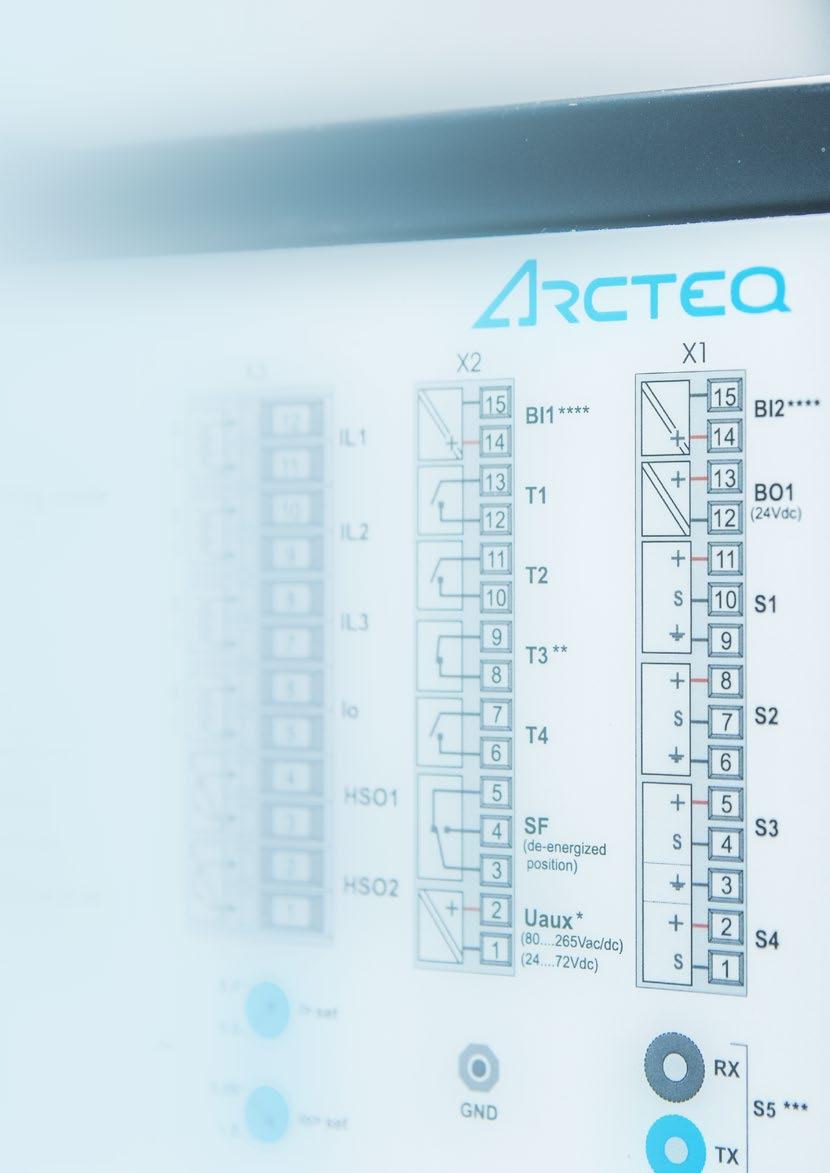
58 58
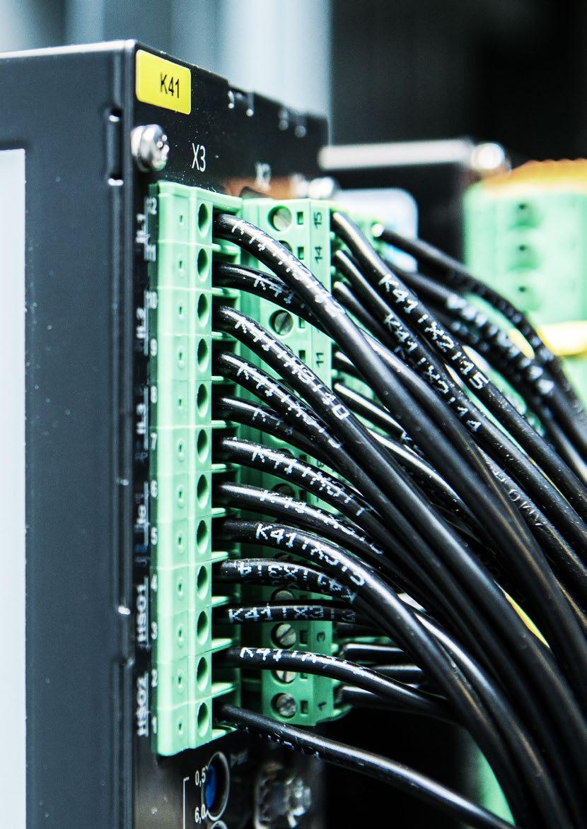
59 59

60 HEADQUARTERS Arcteq Relays Ltd Wolffintie 36 F Vaasa, Finland tel: fax INQUIRIES: sales@arcteq.fi TECHNICAL SUPPORT: support@arcteq.fi Support line (EET 9:00 17:00) AQ200 series product catalogue 1.3EN
RELAYABLE POWER. AQ-200 series protection, control, measurement and monitoring IEDs
 RELAYABLE POWER AQ-200 series protection, control, measurement and monitoring IEDs Contents AQ-200 series protection and control IEDs 3 AQ-200 benefits 3 Arcteq innovation: ultra-accurate measurement technology
RELAYABLE POWER. AQ 200 series protection, control, measurement and monitoring IEDs
 RELAYABLE POWER AQ 200 series protection, control, measurement and monitoring IEDs Contents AQ 200 series protection and control IEDs 3 AQ 200 benefits 3 AQ 200 protection functions 4 AQ 200 control and
RELAYABLE POWER. AQ 200 series protection, control, measurement and monitoring IEDs
 RELAYABLE POWER AQ 200 series protection, control, measurement and monitoring IEDs Contents AQ 200 series protection and control IEDs 3 AQ 200 benefits 3 AQ 200 protection functions 4 AQ 200 control and
Protection relays.
 Protection relays www.vamp.fi Vamp Ltd Vamp Ltd, with a strong experience of designing devices, is an independent supplier of relays and monitoring equipment. The company has an established reputation
Relion 615 series Feeder Protection and Control REF615 Ver. 2.0 Technical Presentation
 Relion 615 series Feeder Protection and Control REF615 Ver. 2.0 Technical Presentation Distribution Automation May 13, 2010 1MRS756407 E Slide 1 Content REF615 Technical Presentation highlights May 13,
Content REF615 Technical Presentation
 Distribution Automation Relion 615 series Feeder Protection and Control Ver. 2.0 Technical Presentation March 30, 2010 1MRS756407 E Slide 1 Content Technical Presentation highlights March 30, 2010 Slide
Numerical motor protection in medium voltage networks Motor Protection and Control REM620
 Guideform Specification 1MRS758530 A Numerical motor protection in medium voltage networks Motor Protection and Control REM620 The configurable motor management relay is intended for protection, control,
MiCOM P521. Fast feeder differential protection
 01 Fast feeder differential protection The relay provides high-speed two-ended current differential unit protection of overhead lines and underground cables in applications such as ring mains and parallel
Feeder/ Motor Protection Relay VAMP 40
 Feeder/ Motor Protection Relay Feeder/motor protection relay Main characteristics Complete protection Comprehensive selection of protection functions for distribution network overhead line feeders, cable
Substation Automation Products. Line differential protection RED670 Relion 670 series
 Substation Automation Products Line differential protection RED670 Relion 670 series For maximum reliability of your power system The RED670 IED (Intelligent Electronic Device) is designed for protection,
MiCOM P521. Fast Feeder Differential Protection
 01 Fast Feeder Differential Protection The relay provides high-speed two-ended current differential unit protection of overhead lines and underground cables in applications such as ring mains and parallel
Substation Automation Products. Transformer protection RET670/650 Relion 670 and 650 series
 Substation Automation Products Transformer protection RET670/650 Relion 670 and 650 series For reliable protection and control of all types of power transformers and reactors The RET670/650 IEDs (Intelligent
PROTECTION, AUTOMATION & CONTROL
 PROTECTION, AUTOMATION & CONTROL 1. DTIVA The members of the DTIVA product line are configured to protect and control the elements of not solidly grounded radial networks. Here the application of Petersen
Substation Automation Products. Generator protection REG670/650 Relion 670 and 650 series
 Substation Automation Products Generator protection REG670/650 Relion 670 and 650 series A new protection standard for your valuable assets Based on ABB s extensive experience, REG670 and REG650 IEDs (Intelligent
Transformer Protection and Control RET630 Numerical transformer protection in medium voltage networks
 GUIDEFORM SPECIFICATION Transformer Protection and Control RET630 Numerical transformer protection in medium voltage networks The freely configurable relay is intended for protection, control, measurement
TWO-WINDING TRANSFORMER DIFFERENTIAL
 E3-TR PROTECTION WITH AUTOMATIC VOLTAGE Because of the control, measuring and monitoring functions implemented, the IED can also be used as a bay control unit. The EuroCAP configuration tool, which is
Relion 615 series Line Differential Protection and Control RED615 Ver. 2.0 Technical Presentation
 Relion 615 series Line Differential Protection and Control RED615 Ver. 2.0 Technical Presentation ABB Oy Distribution Automation July 1, 2009 1MRS756504 B Slide 1 Contents RED615 Technical Presentation
MiCOM P122C Time-Overcurrent Protection
 Protection Relays 01 MiCOM P122C Time-Overcurrent Protection Customer Benefits 1A/5A software setting 4 function keys Compact unit for flush and wall-surface mounting Comprehensive measurements Disturbance
Substation Automation Products. Bay control REC670/650 Relion 670 and 650 series
 Substation Automation Products Bay control REC670/650 Relion 670 and 650 series For optimized control and reliable operation of your switchyard The REC670 and REC650 Bay control IEDs (Intelligent Electronic
Relion 615 series Transformer Protection and Control RET615 Ver. 2.0 Technical Presentation
 Relion 615 series Transformer Protection and Control RET615 Ver. 2.0 Technical Presentation Distribution Automation May 13, 2010 1MRS756901 A Slide 1 Content RET615 Technical Presentation highlights May
MiCOM P521. Fast Feeder Differential Protection. Protection Relays. MiCOM P521 CUSTOMER BENEFITS
 MiCOM 01 MiCOM Fast Feeder Differential Protection The MiCOM relay provides high-speed two-ended current differential unit protection of overhead lines and underground cables in applications such as ring
REL52002 Easergy P3U30, 4L, 4U, 16DI/8DO, Uaux: V, DI: V, RS-485
 Characteristics Easergy P3U30, 4L, 4U, 16DI/8DO, Uaux: 48-230V, DI: 220-230V, RS-485 Main Range of product Product or component type Relay application Device short name [Us] rated supply voltage Type of
Substation Automation Products. Line distance protection REL670/650 Relion 670 and 650 series
 Substation Automation Products Line distance protection REL670/650 Relion 670 and 650 series For maximum reliability of your power system REL670 and REL650 line distance protection IEDs (Intelligent Electronic
Content FPC 400. USER MANUAL Apr Feeder F3 Motor M4 Busbar B3 Transformer T4
 Content FPC 400 USER MANUAL Apr 2017 Feeder F3 Motor M4 Busbar B3 Transformer T4 1 USER MANUAL FPC 400-4/2017 Content Preface Copyright Copyright Iskra d.d. Ljubljana, Slovenia 2016. All rights reserved.
Recloser Controller for feeder protection and automation siemens.com/distribution-automation
 SIPROTEC 7SC80 Control Controller for feeder protection and automation siemens.com/distribution-automation SIPROTEC 7SC80 Control Designed for feeder automation applications This solution allows very fast
SIPROTEC 7SC80 Feeder Protection and Automation Answers for infrastructure and cities.
 www.siemens.com/protection SIPROTEC 7SC80 Feeder Protection and Automation Answers for infrastructure and cities. designed for feeder automation applications This solution allows very fast fault detection
Content FPC 200. USER MANUAL Mar Feeder F1 and F3 Motor M1 and M3 Busbar B2 and B3 Transformer T1 and T3
 Content FPC 200 USER MANUAL Mar 2017 Feeder F1 and F3 Motor M1 and M3 Busbar B2 and B3 Transformer T1 and T3 1 USER MANUAL FPC 200-3/2017 Content Preface Copyright Copyright Iskra d.d. Ljubljana, Slovenia
UNITROL 5000 Excitation Systems for Medium and Large Synchronous Machines
 UNITROL 5000 Excitation Systems for Medium and Large Synchronous Machines Copyright 2000 Photodisc, Inc. 275 371 UNITROL 5000 System Overview The UNITROL 5000 is the most powerful product in the Switzerland
REL52001 Easergy P3U30, 4L, 4U, 16DI/8DO, Uaux: V, DI: V, 2 x RJ-45
 Characteristics Easergy P3U30, 4L, 4U, 16DI/8DO, Uaux: 48-230V, DI: 220-230V, 2 x RJ-45 Main Range of product Product or component type Relay application Configuration type (Cortec) [Us] rated supply voltage
Power Systems Communications Implementation of IEC61850 in a Substation Environment
 Power Systems Communications Implementation of IEC61850 in a Substation Environment 26 October 2009 Reference VEE4700-01 Revision 0 Document Control Document ID: DOCUMENT1 Rev No Date Revision Details
ELG4125: System Protection
 ELG4125: System Protection System Protection Any power system is prone to 'faults', (also called short-circuits), which occur mostly as a result of insulation failure and sometimes due to external causes.
DS Agile C264. Grid Solutions. Dual-bay Modular Substation Controller. Multi-function Controller. Automation and Control. Advanced Communication
 GE Grid Solutions DS Agile C264 Dual-bay Modular Substation Controller The DS Agile C264 substation controller is a sophisticated solution supporting multiple applications and functions for substation
GE Multilin 350 Feeder Protection Relay Specifications
 GE Multilin 350 Feeder Protection Relay Specifications The feeder protection relay shall provide primary protection of medium voltage distribution feeders. The relay shall be equipped with the following
MiCOM P12x/y. Three phase and earth fault overcurrent relays
 01 Three phase and earth fault overcurrent relays The relays provides features for easy adaptation and are suitable for all applications where overcurrent and earth-fault protection are required. The MiCOM
Siprotec 7ST61 / 7ST63
 Siprotec / Numerical overhead contact line protection for AC traction power supply siemens.de/rail-electrification The numerical overhead contact line protection relay Siprotec / is a selective and quick
MiCOM P124 T&D. Self and Dual Powered Overcurrent Relays
 PROTECTION MiCOM P124 Self and Dual Powered Overcurrent Relays MiCOM P124 are numerical relays designed to offer complete overcurrent protection without requiring any external auxiliary supply. They can
Perfect protection smallest space
 www.siemens.com/energy/protection Perfect protection smallest space The SIPROTEC Compact device range redefines protection technology Answers for energy. SIPROTEC Compact is the ideal solution for almost
User Manual. AQ-F215 Simulator
 User Manual AQ-F215 Simulator Instruction manual AQ-F215 Simulator 2 (28) Revision 1.00 Date 16.5.2014 Changes N/A Revision 1.01 Date 13.3.2018 Changes Updated visual look Readability improvements Instruction
Overcurrent and Arc Protection by Reyrolle Alexander Erokhin. 21, 2017 I Berlin
 Overcurrent and Arc Protection by Reyrolle Alexander Erokhin VAR Partner Day September 20-21, 21, 2017 I Berlin Reyrolle Product Range by SIEMENS Challenges We Meet for our Customers Easy-to-use protection
Three phase and earth fault overcurrent relays
 01 Three phase and earth fault overcurrent relays The relays provides features for easy adaptation and are suitable for all applications where overcurrent and earth-fault protection are required. The MiCOM
MiCOM P124. Self and Dual Powered Overcurrent Relays. Protection Relays
 01 Self and Dual Powered Overcurrent Relays are numerical relays designed to offer complete overcurrent protection without requiring any external auxiliary supply. They can be applied to a wide variety
MiCOM P220, P225 and P226C
 PROTECTION MiCOM P220, P225 and P226C MOTOR PROTECTION RELAY MOTOR AND OVERCURRENT PROTECTION RELAY MiCOM P220 MiCOM P225 MiCOM P226C The MiCOM P22x protection relay range is designed for motor protection
SYMAP R Plug in Variants FI, MI, 87M, TI Technical data
 SYMAP R Plug in Variants FI, MI, 87M, TI Technical data 1 Product overview SYMAP R (Retrofit) is a digital protection relay for use in medium and high-voltage power systems. Because of its integrated protection
Protect induction and synchronous motors with one relay
 SEL-710-5 Motor Protection Relay Protect induction and synchronous motors with one relay Patented, accurate thermal protection improves motor availability for production. The 5-inch, 800 480 color touchscreen
SIPROTEC 5 V7.8 Protection, automation and monitoring for digital substations
 SIPROTEC 5 V7.8 Protection, automation and monitoring for digital substations siemens.com/siprotec5 SIPROTEC 5 Table of content Introduction New functions of V7.8 SIPROTEC 5 - the core of Digital Substation
DIGITAL RELAY OF PROTECTION AND AUTOMATION SERIES PC83 AND PC830
 DIGITAL RELAY OF PROTECTION AND AUTOMATION SERIES PC83 AND PC830 PC83 and PC830 series devices are designed to perform the relay protection functions and 6-154 kv networks automation, have different functionality
Protect induction and synchronous motors with one relay.
 SEL-710-5 Motor Protection Relay Protect induction and synchronous motors with one relay. Patented, accurate thermal protection improves motor availability for production. Synchronous motor protection
NEO 3000 Substation System THE FAMILY OF EQUIPMENT DEDICATED FOR POWER UTILITIES. Energy Sector
 THE FAMILY OF EQUIPMENT DEDICATED FOR POWER UTILITIES Introduction The supply of electrical energy occupies an important position in the life of modern society. Operation of commerce, industry, transport,
SR489 SR489. Generator Management Relay. Economical protection, metering, and monitoring functions for small and medium sized generators.
 SR489 Generator Management Relay Economical protection, metering, and monitoring functions for small and medium sized generators. 1 Product Highlights Inputs / Outputs Generator Protection Power Metering
Protective Relays & SCADA Systems
 14 SWITCHGEAR Protective Relays & SCADA Systems SCADA Substation Automation SICAM PAS & PQ Analyzer SICAM PAS (Power Automation System) is a complete substation automation control and protection system
A low-cost, economical solution for distribution feeder protection
 SEL-351A Protection System A low-cost, economical solution for distribution feeder protection Achieve sensitive and secure fault detection using comprehensive protection functions. Track breaker status
S o m e t h i n g b e t t e r t h a n p r o t e c t i v e r e l a y s. automation, control & communication
 S o m e t h i n g b e t t e r t h a n p r o t e c t i v e r e l a y s IEDs with embedded protection, measurement, automation, control & communication digital processing multifunction Monitoring and metering
U lity network. system Q sys. Interconnected P sys. P load Q load. P gen Q gen. Generator network
 SIL-G Feeder & Generator Protection Relay RC FLSH Main characteristics The SIL-G is a relay for primary distribution which can protect a feeder by means of current and voltage functions. It is also provided
Application Notes on Generator Protection Schemes
 Application Notes on Generator Protection Schemes Single Line Diagram Examples 1. Introduction The application notes provide selected single line diagrams for the SIPROTEC 4 generator protection device
Perfect protection smallest space
 www.siemens.com/siprotec Perfect protection smallest space The SIPROTEC Compact device range redefines protection technology Answers for infrastructure and cities. SIPROTEC Compact is the ideal solution
Maximize protection. Sepam series 10, 20, 40, 60, 80. Modular range of digital protection relays
 Maximize protection Sepam series 10, 20, 40, 60, 80 Modular range of digital protection relays Fast Dependable Simple Increase energy availability 100% available energy Fast response Maximum dependability
Catalog Edition 6 siemens.com/protection
 Selection Guide for and Catalog Edition 6 siemens.com/protection Overview of Siemens Protection Catalogs Documentation Selection guide for and Catalog Catalog Catalog Accessoires Catalog Catalogs Manuals
MiCOM P12x/y AREVA T&D. Three phase and earth fault overcurrent relays
 PROTECTION MiCOM P12x/y Three phase and earth fault overcurrent relays The MiCOM P12x/y relays provides features for easy adaptation and are suitable for all applications where overcurrent and earth-fault
MiCOM Agile P746. Grid Solutions. Key Benefits. Numerical Busbar Protection. A Combination of Speed, Security and Selectivity. About MiCOM P40 Agile
 GE Grid Solutions MiCOM Agile P746 Numerical Busbar Protection The MiCOM Agile P746 centralized numerical busbar protection provides complete protection for all voltage levels up to extra voltage busbar
VAMP 50 series. with native IEC and arc flash protection
 VAMP 50 series with native EC 61850 and arc flash protection V VAMP 50 series protection relays VAMP 50 family low and mid range relay series with EC 61850 The VAMP 50 series protection relay family is
Bus Bar Protection Relay B-PRO 4000
 Bus Bar Protection Relay B-PRO 4000 Product Overview The IEC 61850 station bus embedded B-PRO 4000 relay provides complete bus and substation differential protection (low impedance) with CT saturation
Advanced distribution feeder solution with integrated protection, monitoring, and control
 Protection System Advanced distribution feeder solution with integrated protection, monitoring, and control Achieve sensitive and secure fault detection using comprehensive protection functions. Keep track
MiCOM P721 & P723. Numerical High Impedance Differential Relay. Protection Relays. Customer Benefits
 01 MiCOM P721 & P723 Numerical High Impedance Differential Relay The new P72x high impedance differential protection series provides an independent and simple high impedance differential protection solution
7SR21 Non-Directional 7SR22 Directional Overcurrent Relay
 7SR21 Non-Directional 7SR22 Directional Overcurrent Relay Document Release History This document is issue 2010/05. The list of revisions up to and including this issue is: 2010/05 Additional Comms modules
Type SDR reclosers plus controllers and type B-2 recloser bypass switch assembly usa.siemens.com/mediumvoltage
 Overhead solutions Type SDR reclosers plus controllers and type B-2 recloser bypass switch assembly usa.siemens.com/mediumvoltage Overhead switching products Brochure Your outdoor overhead distribution
MiCOM P14x AREVA T&D. Feeder Management Relays
 P R OT E C T I O N MiCOM P14x Feeder Management Relays MiCOM P14x feeder management relays provide an integrated solution for the complete protection, control and monitoring of overhead lines and underground
Function permission: yes/no. Operating range: 0.10 to 30 xin (step 0.01) Operating time: 0.02 to 300 s (step 0.01 s) Activation level 100%
 Operating time: 0.02 to 300 s (step 0.01 s) Activation level 100%") Operating range: 0.10 to 30 xin (step 0.01) 50P(2) Activation level 100% Deactivation level 95% Timer accuracy: 30 ms Operating range: 0.10 to 30 xin (step 0.01) 50N/G(2) Activation level 100% Deactivation
Operating range: 0.10 to 30 xin (step 0.01) 50P(2) Activation level 100% Deactivation level 95% Timer accuracy: 30 ms Operating range: 0.10 to 30 xin (step 0.01) 50N/G(2) Activation level 100% Deactivation
Feeder Terminal. REF 542plus. Product Guide
 Product Guide Issued: January 2007 Status: New Version A/27.04.2007 Data subject to change without notice Features Real-time multifunction protections and switchgear controls: - protections - measurements
(1) Description of Operation 7SR224 Recloser Controller
 Description of Operation 7SR224 Recloser Controller") (1) Description of Operation 7SR224 Recloser Controller DOCUMENTATION SET This document is part of a set. The full list of documents in the set, and the publication numbers under which they can be ordered,
(1) Description of Operation 7SR224 Recloser Controller DOCUMENTATION SET This document is part of a set. The full list of documents in the set, and the publication numbers under which they can be ordered,
MiCOM P14x. Feeder Management Relays
 01 Feeder Management Relays feeder management relays provide an integrated solution for the complete protection, control and monitoring of overhead lines and underground cables from distribution to transmission
SACE Emax 2 Specification guide
 SACE Emax 2 Specification guide Specification Number: 26 01 20.17 Product Name: LOW VOLTAGE POWER CIRCUIT BREAKERS PART 1 GENERAL NOTE: ( ) Indicates option or a selection is to be made for quantity or
THE INTEGRATED TESTING SOLUTION
 Test & Data Management Software TDMS protective relays energy meters transducers power quality CT-VT-PT transformers ground grid circuit breakers batteries surge arresters THE INTEGRATED TESTING SOLUTION
Relion 630 series. Load-shedding controller PML630 High performing load-shedding solution for industrial and utility power networks
 Relion 630 series Load-shedding controller PML630 High performing load-shedding solution for industrial and utility power networks Integrated load-shedding and protection solution The PML630 is a freely-configurable
2 ms arc-flash protection and feeder relay in one platform
 Feeder Protection Relay 2 ms arc-flash protection and feeder relay in one platform Directly monitor and control your system using the 5-inch, 800 480 color touchscreen display. Prevent insulation damage
Modular Smart Grid Power Systems Simulators (Utilities)
") Modular Smart Grid Power Systems Simulators (Utilities) AEL-MPSS SCADA Key features: Several Utilities and Final User options. Modular and scalable applications (from simple to advance complexity). Scalable
Modular Smart Grid Power Systems Simulators (Utilities) AEL-MPSS SCADA Key features: Several Utilities and Final User options. Modular and scalable applications (from simple to advance complexity). Scalable
Feeder Protection REF615 Ver Technical Presentation. ABB Oy Distribution Automation. Prashant Ganoo Regional Product Marketing Manager
 ABB Oy Distribution Automation Prashant Ganoo Regional Product Marketing Manager Feeder Protection REF615 Ver. 1.1 Technical Presentation 9/26/2008-1 - 1MRS756407 C Self Introduction Prashant Ganoo B.E.(ELECT),
Advanced Line Differential Protection, Automation, and Control System. Combine subcycle line protection with traveling-wave fault locating
 Advanced Line Differential Protection, Automation, and Control System Combine subcycle line protection with traveling-wave fault locating Subcycle differential and distance protection minimizes damage
ACOS 300. Reliable protection for network and constructions in medium- and high voltage
 ACOS 300 Reliable protection for network and constructions in medium- and high voltage IDS GmbH: Your competent partner for protection technology Network protection for medium- and high voltage Already
Feeder/Motor Manager Series VAMP 230 VAMP 245 VAMP 255 VAMP 257
 Feeder/Motor Manager Series VAMP 20 VAMP 255 VAMP 257 Feeder/Motor Manager Series Main Characteristics Complete Protection Comprehensive selection of protection functions for distribution network overhead
Landsnet-Icegrid. Requirements for protection and control systems. Principles for the Icelandic power transmission network.
 Landsnet-Icegrid Requirements for protection and control systems. Principles for the Icelandic power transmission network. Introduction.... 4 System requirements... 6 Validity:... 6 Requirements for protection:...
F650 - More than Feeder Protection & Control. GE Consumer & Industrial Multilin
 F650 - More than Feeder Protection & Control F650 Bay Controller A Comprehensive Protection and Control solution for Transmission and Distribution Networks 2 Introduction: What is the F650? Protection,
Line manager VAMP 259 for distance and line differential protection
 Line manager VAMP 259 for distance and line differential protection X Z5 Z4 Z2 Z1 R Z3 v Line Manager VAMP 259 Main characteristics Medium voltage/sub transmission line differential protection (87L) Distance
Metering Devices, Protective Relays, Software and Connectivity. Pre-Wired Control Power, Voltage and CT Inputs
 .3 Features and Benefits Saves installation time and cost One part number to order; no need to worry that any part has been left out Pick the meter or meters you need as it is designed to fit various Eaton
e 2 TANGO -400 Overcurrent Relay K Catalogue EN
 e 2 TANGO -400 Overcurrent Relay K-33.1.3 Catalogue EN We Create Ideas With Power! e 2 TANGO-400 protection relay is a solution developed by ELEKTROMETAL ENERGETYKA SA R&D department consisting of engineers
Products Portfolio. Pole mounted Vacuum Recloser
 Products Portfolio Pole mounted Vacuum Recloser Efacec Switchgear Efacec Switchgear is a leading company in Portugal and a worldwide reference in the development of solutions for power generation, transmission,
Substation automation products. MicroSCADA Pro for substation automation
 Substation automation products for substation automation Perfect control anywhere, anytime is an investment for today and tomorrow. Start, for instance, with monitoring or gateway functionality and integrate
Agile P24xM. Grid Solutions. Protection and Control. Motor Management Series. Metering and Monitoring. Advanced Communications.
 GE Grid Solutions Agile P24xM Motor Management Series GE's, a member of the field proven P40 Agile protective relay platform, and has been designed for the protection, control, and management of medium
GE Power Management. MMII Intelligent MCC Controller
 A concept that will offer reduced overall installed cost and production efficiency through information availability to operators and maintenance. Presentation Overview 6 Applications 6 Protection and Control
One relay for safety and process continuity
 Motor Management Relay One relay for safety and process continuity Improve safety at each motor control center (MCC) with secure, fast arc-flash detection. Use the enhanced thermal model for more precise
Approval...6. Current Revision...7. Introduction... 8 About PJM Manuals... 8 About This Manual... 8 Using This Manual...9
 PJM Manual 07: PJM Protection Standards Revision: 3 Effective Date: May 24, 2018 Prepared by System Planning Division Transmission Planning Department PJM 2018 Table of Contents Table of Contents Approval...6
p. 1 p. 9 p. 26 p. 56 p. 62 p. 68
 The Challenges and Opportunities Faced by Utilities using Modern Protection and Control Systems - Paper Unavailable Trends in Protection and Substation Automation Systems and Feed-backs from CIGRE Activities
Mehta Tech, Inc. TRANSCAN IED For Multi-Function, Multi-Speed Recording
 Mehta Tech, Inc. TRANSCAN IED For Multi-Function, Multi-Speed Recording Two independent, simultaneously operating recorders in one package Triggering on input quantities and calculated values, such as
GRD110 FEATURES APPLICATION
 FEATURES Overcurrent protection for phase and earth faults with IDMTL or DTL. Three instantaneous elements with DTL. Programmable reset characteristics. Sensitive earth fault protection (SEF). Restricted
Substation Automation Products. High impedance differential busbar protection REB650 Relion 650 series
 Substation Automation Products High impedance differential busbar protection REB650 Relion 650 series One IED for a wide range of high impedance differential protection applications ABB introduces a new,
SEL-487B. A Powerful Solution for Busbar Differential Protection. Bus Differential and Breaker Failure Relay
 Bus Differential and Breaker Failure Relay A Powerful Solution for Busbar Differential Protection Features and Benefits Select the for the differential protection of busbar systems with up to 18 terminals.
UR Universal Relay Series
 GE Digital Energy UR Universal Relay Series Revision 5.90 Release otes GE Publication umber: GER-4401 Copyright 2010 GE Multilin Summary Overview GE Multilin issues the UR 5.90 release that introduces
MiCOM P111. Three phase and earth fault overcurrent relays
 Three phase and earth fault overcurrent relays The relays are suitable for all the application where overcurrent and/or earth-fault protection are required. Thanks to its favorable price vs technical features
Identify and understand the operation of common bus. After this presentation you will be able to: Identify common bus arrangements
 Introduction to Bus Protection By Matt Horvath, P.E. November 6, 2018 Electrical Buses Physical and Electrical Junction A bus is a critical element of a power system, as it is the point of convergence
Relion 615 series. Feeder Protection and Control REF615 Product Guide
 Relion 615 series Feeder Protection and Control Product Guide Contents 1. Description...3 2. Standard configurations...3 3. Protection functions...8 4. Application...16 5. Supported ABB solutions...22
7SR11 and 7SR12 Description of Operation
 7SR11 and 7SR12 Description of Operation Document Release History This document is issue 2012/02. The list of revisions up to and including this issue is: 2012/02 AC auxiliary power supply added 2012/01