UNIVERSITY OF THESSALY POLYTECHNIC SCHOOL DEPARTMENT OF ELECTRICAL AND COMPUTER ENGINEERING
|
|
|
- Albert Garrett
- 6 years ago
- Views:
Transcription

1 UNIVERSITY OF THESSALY POLYTECHNIC SCHOOL DEPARTMENT OF ELECTRICAL AND COMPUTER ENGINEERING Study of video streaming over web characteristics and improvement of existing algorithms in order to maximize the QoS Thesis Zervas Triantafyllos Supervisor Professors: Korakis Athanasios Assistant Professor Argyriou Antonios Lecturer Volos, September 2015
2 Zervas Triantafyllos Page 2
3 ΠΑΝΕΠΙΣΤΗΜΙΟ ΘΕΣΣΑΛΙΑΣ ΠΟΛΥΤΕΧΝΙΚΗ ΣΧΟΛΗ ΤΜΗΜΑ ΗΛΕΚΤΡΟΛΟΓΩΝ ΜΗΧΑΝΙΚΩΝ ΚΑΙ ΜΗΧΑΝΙΚΩΝ ΥΠΟΛΟΓΙΣΤΩΝ Μελέτη των χαρακτηριστικών της μετάδοσης βίντεο μέσω διαδικτύου και βελτίωση των υπαρχόντων αλγορίθμων με σκοπό τη βελτίωση της ποιότητας εξυπηρέτησης Διπλωματική Εργασία Ζέρβας Τριαντάφυλλος Επόπτες Καθηγητές: Κοράκης Αθανάσιος Επίκουρος Καθηγητής Αργυρίου Αντώνιος Λέκτορας Εγκρίθηκε από την διμελή εξεταστική επιτροπή την 6 η Σεπτεμβρίου 2015 Κοράκης Αθανάσιος Επίκουρος Καθηγητής Αργυρίου Αντώνιος Λέκτορας Βόλος, Σεπτέμβριος 2015 Zervas Triantafyllos Page 3
4 Zervas Triantafyllos Page 4
5 Διπλωματική Εργασία για την απόκτηση του Διπλώματος του Μηχανικού Ηλεκτρονικών Υπολογιστών, Τηλεπικοινωνιών και Δικτύων του Πανεπιστημίου Θεσσαλίας, στα πλαίσια του Προγράμματος Προπτυχιακών Σπουδών του Τμήματος Ηλεκτρολόγων Μηχανικών και Μηχανικών Υπολογιστών του Πανεπιστημίου Θεσσαλίας... Ζέρβας Τριαντάφυλλος Διπλωματούχος Μηχανικός Ηλεκτρονικών Υπολογιστών, Τηλεπικοινωνιών και Δικτύων Πανεπιστημίου Θεσσαλίας Zervas Triantafyllos Page 5
6 Zervas Triantafyllos Page 6
7 Declaration of Authorship I, Triantafyllos Zervas, hereby certify that this thesis titled, "Study of video streaming over web characteristics and improvement of existing algorithms in order to maximize the QoS" has been composed by me and is based on my own work, unless stated otherwise. The research was carried out wholly during the candidacy for the graduate degree of Diploma of Science in Computer and Communication Engineering at the University of Thessaly, Department of Electrical and Computer Engineering, Volos, Greece. I have documented every source and material I have quoted or consulted at the Bibliography section at the end of this thesis. Copyright 2015 by Zervas Triantafyllos "The copyright of this thesis rests with the author. No quotations from it should be published without the author s prior written consent and information derived from it should be acknowledged" Zervas Triantafyllos Page 7
8 Zervas Triantafyllos Page 8
9 Στους γονείς μου, Ιωάννη και Κωνσταντίνα. Zervas Triantafyllos Page 9
10 Ευχαριστίες Με την περάτωση αυτής της εργασίας, θα ήθελα να ευχαριστήσω τον επιβλέποντα Επίκουρο καθηγητή του τμήματος Ηλεκτρολόγων Μηχανικών και Μηχανικών Υπολογιστών, κ. Αθανάσιο Κοράκη για την εμπιστοσύνη που έδειξε στο πρόσωπό μου, δίνοντάς μου την ευκαιρία να ασχοληθώ με το συγκεκριμένο θέμα. Επίσης, θα ήθελα να ευχαριστήσω τους εργαζόμενους στο Εθνικό Κέντρο Έρευνας και Τεχνολογικής Ανάπτυξης (ΕΚΕΤΑ) Βόλου, οι οποίοι με βοήθησαν να ξεπεράσω τυχόν δυσκολίες που προέκυψαν και χαίρομαι που συνεργάστηκα μαζί τους σε αυτή αλλά και σε προηγούμενες εργασίες. Ιδιαίτερη ευχαριστία θα ήθελα να απευθύνω στον διδακτορικό φοιτητή Δονάτο Σταυρόπουλο για τις ουσιώδεις υποδείξεις και παρεμβάσεις που βοήθησαν σε μεγάλο βαθμό στην εκπόνηση της παρούσας εργασίας. Ένα μεγάλο ευχαριστώ στους φίλους μου, στους ανθρώπους που πέρασα χαρούμενες και λυπημένες στιγμές μαζί τους και με βοήθησαν με τη φιλία τους και την ψυχολογική τους υποστήριξη σε αυτό το ταξίδι της γνώσης μέχρι και το τέλος. Τέλος, δεν θα μπορούσα να μην αναφέρω τα άτομα που με διευκόλυναν με όποιο τρόπο μπορούσαν κατά τη διάρκεια των σπουδών μου, τους γονείς μου, τις ξαδέλφες μου και τη θεία μου. Είναι οι άνθρωποι που μοιράστηκαν μαζί μου τις χαρές και τις απογοητεύσεις μου και στάθηκαν σθεναρά δίπλα μου ο καθένας με τον τρόπο του. Θα είναι για μένα η δύναμη που θα με ωθεί να συνεχίσω το ταξίδι της γνώσης, καταφέρνοντας ακόμη περισσότερα. Ζέρβας Τριαντάφυλλος Βόλος, 2015 Zervas Triantafyllos Page 10
11 CONTENTS Image/Diagrams Catalog 15 Tables Catalog 16 Abstract 17 Key Words 17 Chapter 1: Introduction Problem Analysis Preparation Video Streaming Related Work VLC media player Structure 21 Chapter 2: Protocols Real-Time Protocol (RTP) General Information Characteristics Packet Format Mixes and Translators Real-Time Control Protocol (RTCP) Characteristics RTCP Packet Format Sender Report (SR) Receiver Report (RR) Source DEScription RTCP packet (SDES) 29 Zervas Triantafyllos Page 11
12 CONTENTS Goodbye RTCP packet (BYE) Application defined packet (APP) User Datagram Protocol 31 Chapter 3: VLC's Streaming Procedure Sender side Input Stage Transcoding Stage Sending Stage Receiver Side 36 Chapter 4: The Proposed Technique Preparation Calculation of bitrate Estimation of the quality of the network Report transmission Implementation (Server Side) Start mechanic and messages 42 Chapter 5: Scenarios and Results NITOS wireless testbed Outdoor nodes Tholos indoor testbed Preparation, setup and parameters Description of the experiments Results and explanation 52 Zervas Triantafyllos Page 12
13 CONTENTS Bitrate Packet loss PSNR 58 Chapter 6: Conclusions Conclusions Future Work 68 Bibliography 69 Zervas Triantafyllos Page 13
14 IMAGE/DIAGRAMS CATALOG Figure 1.1 Video streaming procedure 19 Figure 1.2 VLC logo 21 Figure 2.1: RTP packet format 23 Figure 2.2: Sender Report format 26 Figure 2.3: Receiver Report format 28 Figure 2.4: SDES format 29 Figure 2.5: BYE format 29 Figure 2.6: APP format 30 Figure 2.7: UDP packet format 31 VLC's Streaming Procedure's diagram 32 Proposed Technique's diagram 37 Figure 5.1: NITOS testbed 43 Figure 5.2: Outdoor testbed 44 Figure 5.3: Outdoor Wi-Fi node 45 Figure 5.4: Indoor testbed topology 46 Figures 5.5 and 5.6: Icarus Node 47 Bitrate results diagram 52 Packet loss results diagram 55 PSNR results diagram 58 Figure 5.7: Screenshots from the outcomes of the first scenario 59 Figure 5.8: Screenshots from the outcomes of the second scenario 61 Figure 5.9: Screenshots from the outcomes of the third scenario 62 Figure 5.10: Screenshots from the second set of experiments 63 Zervas Triantafyllos Page 14
15 IMAGE/DIAGRAMS CATALOG Figure 5.11: Screenshots from the fourth scenario 64 Figure 5.12: Screenshots the fifth scenario 65 Figure 5.13: Screenshots from the sixth scenario 66 Figure 5.14: Screenshots from the second set of experiments 67 TABLES CATALOG Table 5.1: Specification list for Outdoor nodes 45 Table 5.2: Specification list for Icarus nodes 47 Zervas Triantafyllos Page 15
16 ABSTRACT The goal of this thesis is to find a way to make video streaming on demand more reliable through wireless networks. Using the VLC open-source program, we implemented an adaptive bitrate streaming technique over the RTP network protocol, which adapts the video bitrate of the streaming video according to the capacity and the situation of the wireless channel. Once we implemented the technique and adapted it to the desired protocol, we created six different scenarios in order to test its efficiency and the quality and smoothness of the transmitted video on NITOS wireless testbed. The results were very encouraging, compared to the original VLC program, and there is great improvement especially at the worst case scenarios. KEY WORDS vlc, wireless, bitrate adaptation, video streaming, RTP, RTCP, adaptive bitrate streaming Zervas Triantafyllos Page 16
17 CHAPTER 1: INTRODUCTION 1.1 Problem analysis Video on demand are systems which have become quite popular in our everyday life, as for example satellite TV, online WebTV and video-sharing websites such as DailyMotion and YouTube. Those services mainly use the more secure wired communication technology. But due to recent advancements in cellular technology, more and more people stream videos to their phones and although the servers use wired technology for the transmission of the data, in this case the last hop will always be wireless. Wi-Fi and Cellular data service are only 2 examples of wireless data communications where video streaming is not as easy as in wired communications due to the fact that the wireless channels are affected by numerous factors. Weather conditions, congestion and the distance between the sender and the receiver are some of the reasons that make the transmission of data through wireless channels much more difficult. All the previous factors affect the quality and the smoothness of the video. When streaming via a wireless channel, we experience distortion on the image of the video, freezes during the transmission of the video due to extreme packet loss and distorted audio. Therefore, it is mandatory to find a technique that takes into consideration all the above and produces the best possible result. 1.2 Preparation Firstly, we had to find information about video streaming and especially video streaming ondemand. We had to learn in which areas of this subject we can interfere and how are we going to implement them. We decided that creating an adaptive bitrate technique would be a great choice since we couldn't find too many implementations. For the next step, we had to decide which open source program to use in order to implement our technique and if this program can be installed in the NITOS testbed. After extend research, we decided that the VLC media player is the best candidate since it is open source and also it is a program which is constantly getting updated, it can be installed in the NITOS testbed, and we can find help online. In this thesis, we wanted to implement a technique using a different protocol than the standard TCP, which is used in HTTP networks. We wanted to find a protocol which was not used commonly and there hasn't been many implementations regarding this protocol. Still we wanted it to be trustful and ensure that the results that we hope we will receive will be better than the original VLC's. After some research on TCP and UDP, two basic protocols, we found the RTP protocol. A relatively newer protocol than the previous two, it was designed for live video streaming but it can also be used for video streaming on-demand. Next, we had to do some research about techniques that have already been implemented on RTP regarding the rate. The most relevant papers and articles we read are presented in the next sub-chapter. Zervas Triantafyllos Page 17
18 1.2.1 Video Streaming Recent advances in computing technology and high speed networks have enabled us to transmit real-time video and audio via the Internet. The real-time multimedia, as the name suggests, must be transferred real-time without any delays in order to avoid annoying pauses and cuts during the transmission of the video. In this thesis, we are concerned with the transmission of stored video in a server. There are two ways to watch a video via the Internet, either download the video or stream it. The second way is what concerns as and the general term for this is video streaming on-demand. While in the first one, the user downloads the video and then watches it without worrying about the network conditions, during the video streaming on-demand, the user doesn't need to download the video file, but he streams it directly from the server without having to save it in his computer. Although, downloading the file takes more time than streaming it, the quality of the video is better than streaming since the transmission of the video can suffer from loss, delay and small bandwidth that can worsen the quality of the outcome. Researchers have been trying to create a better outcome using this technique by a Quality of Service (QoS) system which evaluates the situation in the network and adjust the stream to those conditions. To fully understand how streaming works, the next pictures shows exactly that. Figure 1.1 Video streaming procedure Zervas Triantafyllos Page 18
19 The raw video and audio goes through video and audio compression and later they are saved at a storage device. After the receiver requests that specific audio and video, the streaming server transfers video and audio to the QoS control were both of them are modified and getting prepared for transfer according to the network conditions. Then the video and audio are transferred to the transport protocol which packetizes both audio and video and it is responsible to safely transfer all the data across the internet, so that the receiver won't experience problems such as packet loss which will affect the outcome. The packets that were successfully transmitted to the receiver are going through the transport protocol and then they are being processed by the application layer. After the application layer, the video and audio are being decoded and in order to synchronize those two, media synchronization mechanisms are applied. Finally, if the video and audio are synchronized, they are being broadcasted to the receiver Related Work We did an extended research across the Internet and we found many different approaches that helped us understand more about video streaming and adaptive bitrate. The first paper we came across was "Online Smoothing of Variable-Bit-Rate Streaming Video" by Subhabrata Sen, Jennifer L. Rexford, Jayanta K. Dey, James F. Kurose and Donald F. Towsley which proposes an online smoothing bandwidth model that takes into account playback delay, client and server buffer sizes, server processing capacity, and frame size prediction techniques. Another paper that was really helpful since it concerned rate shaping was "Streaming Video Using Dynamic Rate Shaping and TCP Congestion Control" by Stephen Jacobs and Alexandros Eleftheriadis where they propose a new technique for streaming video taking into account the dynamic rate shaping and TCP congestion control. Furthermore, the paper "Real-Time System for Adaptive Video Streaming Based on SVC" by Mathias Wien, Renaud Cazoulat, Andreas Graffunde, Andreas Hutter and Peter Amon presents how the inserted the Scalable Video Coding (SVC) into a platform for multimedia adaptation which contains a full MPEG-21 chain. Moreover, in the "Secure Scalable Video Streaming for Wireless Networks", Susie J. Wee and John G. Apostolopoulos propose a new wireless video streaming system which streams video to heterogeneous clients over time-varying communication links. Finally, through the "Transporting Real-Time Video over the Internet: Challenges and Approaches" by Dapeng Wu, Yiwei Thomas Hou and Ya-Qin Zhang, we got informed about rate control, Quality of Service and other valuable information about video streaming. Zervas Triantafyllos Page 19

20 1.2.3 VLC media player Figure 1.2 VLC logo VLC media player (commonly known as VLC) is a free and open-source media player and streaming media server written by the VideoLAN project. VLC supports many file formats and many streaming protocols. This media player is also capable of transcoding multimedia files in order to stream over computer networks. Due to the large number of encoding and decoding libraries, it was a simple and easy choice to use this specific media server to perform our experiments on. The source code likewise our technique was written in C programming language. It is compatible with every operating system and there has been a mobile version for Android devices since Structure Here is the structure of this thesis: In Chapter 2, we analyze the network and transfer protocols that we have been used in order to implement our technique. In Chapter 3, we present the procedure that VLC follows in order to start the video streaming, both from the sender and the receiver side. In Chapter 4, we explain our technique in full detail and the way it was implemented on VLC. In Chapter 5, we present the results and screenshots we collected from the six different scenarios and compare them to the original VLC. Finally in Chapter 6, we present our conclusions after the execution of the experiments. Zervas Triantafyllos Page 20
21 CHAPTER 2: PROTOCOLS 2.1 Real-Time Protocol (RTP) General Information RTP is a real-time end-to-end network protocol that is used commonly over transport protocols such as UDP and TCP for delivering audio and video over IP networks. RTP is generally used in streaming media in telephony for example, video teleconference applications and television services. RTP is commonly used together with the control protocol RTCP. While the first one is responsible for the transmission of data, the second one is responsible for collecting statistics and monitor the QoS (Quality of Service). A RTP session is usually composed of a RTP port number (UDP port), a RTCP port number (consecutive UDP port) and the participant's IP address Characteristics One of the advantages of using this protocol is the payload type and the source identification. Every packet that is transmitted via the RTP protocol has a specific field which can help the receiver recognize the payload type of the video and the sender from which it received the packet. The second characteristic is very important because in this way the receiver can assume more than one video files at the same time from different senders without making errors by mixing these files together. Another advantage of using this protocol is the sequence numbering. Packet loss is one of the major problems when it comes to wireless communications and sequence numbering can be a way to reduce this. Using this information, the receiver can re-order the packets that receives and that gives the opportunity to create a retransmission mechanism by requesting each time a specific packet that was lost. Finally, the last advantage of this protocol is timestamping. This enables the receiver to play back the received samples at appropriate intervals. In case of several media streams, the timestamps are unique for every stream. Although this protocol comes with many advantages, there are some disadvantages as well. RTP doesn't guarantee timely delivery of packets and if it doesn t keep the packets in sequence. For this reason it transmits the sequence number so that the receiver can re-order them. Furthermore, RTP doesn't have a mechanism to cope with packet loss and consequently it leaves that to the application layer to decide whether they need to implement one. A retransmission mechanism can affect the video streaming positively since it will resend packages with new or updated information that may solve the consequences from the original loss. Zervas Triantafyllos Page 21
22 2.1.2 Packet Format Figure 2.1: RTP packet format The first twelve octets appear in every RTP packet and the CSRC identifiers field is added only by a mixer. Firstly, we will analyze the 32 control bits: Version (V): It represents the version of RTP. The value of this field is always 2. (2 bits) Padding (P): If the padding bit is set, it means that there are additional padding octets that are not part of the payload. The last octet shows how many octets should be ignored, including itself. Padding may be important for applications with fixed block sizes. (1 bit) Extension (X): If the extension bit is set, it indicates that there is an extension after the fixed header. (1 bit) CSRC Count (CC): The number of contributed source identifiers (CSRC) that come after the fixed header. (4 bits) Marker (M): It is a general marker which gives the opportunity to the profile to allow certain events. (1 bit) Payload Type (PT): This field determines the format of the RTP payload and how it will be interpreted. There are a number of payload types such as G.721, G.722 and G.728 speech codecs, JPEG and H.264 video codecs. A receiver will ignore packets with payload types that cannot be identified. (7 bits) Zervas Triantafyllos Page 22
23 Sequence number (sequence number): The value of this field increases each time a RTP data packet is sent. It can be used to detect packet loss and restore packet sequence. The starting value of this field is random. (16 bits) Timestamp (timestamp): The timestamp corresponds to the sampling instant of the first octet in the RTP data packet. The initial value of the timestamp is random, as it was for the sequence number. Several RTP packets may have the same timestamp if they are all generated at once. (32 bits) Synchronization SouRCe identifier (SSRC): This identifier is a random value that represents the source of the packet within the session. This identifier should be unique so that there are no problems at the receiver. An RTP implementation must have a mechanism to solve the problem if there are more than one same identifiers. In case of change of transport address by the source, the source must also generate a new SSRC identifier. (32 bits) Contributing SouRCe identifiers (CSRC): The list of identifiers can be up to 15 identifiers. It represents the contributed sources for this payload. The number of identifiers is given by the CC field. In case of more than 15 CSRC, only 15 can be identified. These specific fields are being added by mixers using the SSRC of the contributing sources. (32 bits each) Mixers and Translators Since RTP can support multicast transmission, it must have a way to coordinate the transmission. A mixer can combine packets from multiple senders and send them to one or more receivers. As mentioned before, the mixer adds the source identifications from all the contributing sources in the CSRC field of the RTP packet. Due to the fact that the receiving of packets from different sources probably won't be at the same time, the mixer operates at its own timing and makes timing adjustments. If we need to change the format of the data in the packet, the translator can achieve that, for example change the encoding thus the data payload and the timestamp in which case the translator must assign new sequence numbers. In most cases, the receivers don't know that a translator is present. Zervas Triantafyllos Page 23
24 2.2 Real-Time Control Protocol (RTCP) Characteristics RTCP is a control protocol, which is implemented on top of UDP. RTCP is always implemented along with RTP since it provides feedback to the session participants about the quality of the stream. RTCP protocol is responsible for: QoS monitoring and congestion control Identification Session size estimation and scaling In order for the application to implement a congestion control method, the RTCP provides quality-of-service information about the stream. This information is being sent in the form of a sender (SR) and a receiver (RR) report. Those packets contain information about packet loss, delay and delay jitter. The previous information can also be used in network management tools and in order to implement adaptive encoding. An RTCP packet also carries an identifier which can be used to obtain information about the participants of the RTP session. This identification can also include information such as the user's name and address. The RTCP packets are sent periodically by each member, so if we have many participants in each session that means that they are going to be many RTCP packets that will affect the traffic and the bandwidth. RTCP takes maximum of 5% of the session bandwidth in order to avoid some of the following consequences that RTCP may cause: Congestion due to high number of RTCP packets Large delays between the arrival of each packet Large size of the membership table Zervas Triantafyllos Page 24
 Receiver Report (RR) Source Description (SDES) Goodbye (BYE) Application-defined packet (APP) 2.2.2.1 Sender Report (SR) Figure 2.")
25 2.2.2 RTCP Packet formats There are 5 different types of packet formats with each one having a different payload type. Each packet starts with a header that is similar to the RTP packet. Those types are: Sender Report (SR) Receiver Report (RR) Source Description (SDES) Goodbye (BYE) Application-defined packet (APP) Sender Report (SR) Figure 2.2: Sender Report format The sender report packet consists of three standard sections and a fourth profile specific extension. The first section, the header, is 32 bits long and consists of: Version (V): The version of RTP. This is the same as the RTP packets and the value of this field is 2. (2 bits) Padding (P): If this bit is set, this particular packet has some additional padding octets at the end which are not part of the information. The last octet contains the number of octets that should be ignored including itself. Padding can be used by encryption algorithms with fixed block sizes. (1bit) Zervas Triantafyllos Page 25
26 Reception report Count (RC): The number of reception reports in this packet. (5 bits) Packet Type (PT): This field informs the receiver of the type of packet it's receiving. For the SR packet the value is 200. (8 bits) Length (length): The length of this packet in 32-bit words minus one, taking into account the header and any padding. (16 bits) Synchronization SouRCe identifier (SSRC): The SSRC of the sender of this SR packet. (32 bits) The second section is 20 octets long and it appears only in sender reports. This section contains the sender information as it appears also in the picture above. The sender information consists of: NTP Timestamp most and least significant word: These two fields contain the high and low parts of the Network Time Protocol (NTP) timestamp which indicate when this report was sent. This timestamp can be used combined with the timestamps from the receiver reports to measure round-trip propagation. (64 bits, 32 bits for each word) RTP Timestamp: This timestamp, as well as the previous one, corresponds to the sending time of this packet using the same units and the same random offset as the RTP timestamps in data packets. (32 bits) Sender's packet count: The numbers of data packets sent by the RTP from the time the transmission started up until the moment that this report was sent. (32 bits) Sender's octet count: The number of payload octets transmitted in RTP data packets by the sender from the start of the transmission until this sender report. (32 bits) The third section contains the zero or more reception blocks. Each reception block includes information from one source. In the case of a SSRC change, receivers should stop carrying that information. These statistics are: SouRCe identifier for each source (SSRC_n): The source identifier of the source to whom those statistics refer to. (32 bits) Fraction lost: The fraction of data packets that were lost since the previous report. (8 bits) Cumulative number of packets lost: The total number of packets that were lost since the beginning of the transmission. (24 bits) Extended highest sequence number received: The low 16 bits include the highest sequence number that was received from an RTP data packet and the most significant 16 bits extend this sequence number with the corresponding count of sequence cycles. (32 bits) Zervas Triantafyllos Page 26

27 Interarrival jitter: An estimate of the RTP data packet interarrival jitter measured in timestamp units. The value of this field is calculated by the mean deviation of the difference in packet spacing at the receiver compared to the sender for a number of packets. (32 bits) Last SR timestamp (LSR): This field corresponds to the middle 32 bits of the 64 bits of the NTP timestamp which are part of the most recent sender report. If there were no SR before, the value would be zero. (32 bits) Delay since Last SR (DLSR): The delay between the receiving of the last SR packet and the sending of the reception report block. (32 bits) Receiver Report (RR) Figure 2.3: Receiver Report format The format of the Receiver Report is the same as the one of the Sender Report except: The value of the packet type field is 201. The sender info contains only the SSRC of the sender of this report. Zervas Triantafyllos Page 27

28 Source DEScription RTCP packet (SDES) Figure 2.4: SDES format The SDES packet is a three level structure which contains the header and zero or more chunks. The header is the same as the rest of the RTCP type of packets with two differences. The SC (Source Count) field which contains the number of chunks that are included in the packet and the value of the packet type (202). Each chunk contains the Source and Contributing Source identifiers of the sender and a specific SDES item. The defined SDES items are: the canonical end-point identifier (CNAME) with the format user@host, the user name (NAME), the address ( ), the phone number (PHONE), the geographical user location (LOC), the application or tool name (TOOL), the notice (NOTE) and the private extensions (PRIV) Goodbye RTCP packet (BYE) Figure 2.5: BYE format The BYE packet informs the receivers that a source is leaving the session and a prolonged silence initiates. This packet can also include textual information about the reason why the sender left the session. Zervas Triantafyllos Page 28
29 Application defined packet (APP) Figure 2.6: APP format This type of packet is used for experiments as new applications and features are developed. The fields that differ from the previous packet types and they are not analyzed are the following: Subtype: As name suggests, this field can be used as a subtype in order to allow a set of APP packets to be defined under a unique name. (5 bits) Application Name: A name that was chosen by the person who defined the set of APP packets. This name must be unique and it is interpreted as a sequence of four ASCII characters. (4 octets) Application-defined data: This field's length varies in value because the information that can be included doesn't have a specific size. This information is interpreted by the application and not by the RTP. Zervas Triantafyllos Page 29

30 2.3 User Datagram Protocol (UDP) UDP is a lower-layer transport protocol upon which the RTP and RTCP protocol are implemented. UDP can multiplex data streams from different applications that are running on the same machine and IP addresses. As for the error control, UDP employs the checksum to detect bit errors. If a single or multiple bit error is detected then UDP discards the packet so that protocols like UDP will not receive a corrupted packet. Although UDP has a mechanism for error control, it doesn t have a retransmission feature or a congestion control one. That means that UDP relies to the application layer or higher protocols to deal with these problems whenever they occur. Although TCP can guarantee a more reliable transfer of data, UDP is the transport protocol that is commonly used for video streams due to the fact that retransmissions can cause delays in the stream. Lastly, since it is stateless and simple, it is ideal for streaming media applications as for example IPTV, VoIP etc. UDP's packet format is shown below: Figure 2.7: UDP packet format Zervas Triantafyllos Page 30
31 CHAPTER 3: VLC's STREAMING PROCEDURE Input Demux Es_out_Send Decoder FIFO DecoderThread Video Decoder Audio Decoder Transcode Video Encoder Audio Encoder RTP packetization StreamFIFO Sending Zervas Triantafyllos Page 31
32 In this chapter, we will analyze the procedure that VLC follows in order to prepare the data packets for sending and the procedure that the receiver follows in order to receive those packets. Considering the sender side, the procedure can be divided into three stages: the Input stage, the Transcoding stage and the Sending stage. As for the receiver side, after the initialization of VLC, the procedure is iterative. We will now provide more details about the two previous procedures in the next two sub-chapters. 3.1 Sender side After the initialization of VLC, the program creates three threads, which don't run simultaneously. Each thread has a FIFO list which contains packets that will be transferred to the next FIFO after the thread finishes the editing of the packet. Once the FIFO empties, that thread yields and the next thread wakes up with a full FIFO list Input stage This first stage contains the first three steps shown in the chart above. After the initialization of VLC, the reading and translating of the command line and the setup of the communication, the Input thread starts to read from the file that was provided in the command line. In order to prepare the packet for sending, VLC strips the sample that the Input thread provides from all encoding. Each time the Input thread reads from the file, it adds the sample to the input FIFO in order to start the demultiplexing to start. During the demultiplexing (in VLC it is referred to as demuxing), a procedure is constantly checking the input FIFO whether there is a new sample to start the demuxing. After the procedure obtains the sample, it strips it from all muxing so that later the Decoder thread can remove the audio and video encoding before the sample reaches the transcoding. Once the demuxing of a sample is complete then the sample is added to the decoder FIFO by using the es_out_send procedure. In order to start the decoding, the demuxing of all samples must be complete and the input FIFO must be empty. Once the input FIFO empties, it releases the mutex in order to wake up the Decoding thread and start the decoding of the samples. Zervas Triantafyllos Page 32
33 3.1.2 Transcoding stage Once the mutex from the Input thread is released, the Decoder thread wakes up and the decoding starts. The thread picks a block from the decoder FIFO and calls the procedure which is responsible for the decoding process. The codecs of the file are being recognized at the start of the stream by VLC. If the block contains video content, then the Decoder thread summons the appropriate video decoder procedure. VLC can support numerous codecs but in our case we will only use mp4 files. VLC calls the decoding procedure from avccodec. In other case, if the block contains audio content, then specifically for our case, VLC summons the decoding procedure from mpeg4audio. Once the decoding finishes, then the transcoding can start. What happens after the decoding stage depends on the arguments of the command line. If the user specified a codec in which he wants the VLC to encode the video then the appropriate block will go through the transcoding process. If the user didn't mention a specific codec on the command line, then the transcoding step is overlooked. After the block enters the transcoding step, it depends on the content whether VLC will summon the audio or the video encoder. After the video or audio is encoded, then it passes through a "record" filter which makes the output video recordable on the receiver side. Once the encoding is finished then the packetization process starts. Depending on the codec that was mentioned on the command line, the VLC summons the appropriate packetization procedure to packetize the data. For instance, for the two previous codecs, VLC summons mpeg4audio_packetizer for audio and avccodec_packetizer for video. After the completion of this step, we move to the muxing step. If the user mentioned a specific muxer on the command line, then the block of data must be muxed with that specific muxer before the RTP packetization process. Otherwise, the block of data moves directly to the RTP packetization process. This specific process adds the headers that were mentioned in Chapter 2 in the RTP packet format. When the RTP packetization finishes, VLC adds the finished packet to the sending FIFO. Once the decoding FIFO empties, then the Decoder thread releases the same mutex that the Input thread released and the Sending thread wakes up. Zervas Triantafyllos Page 33
34 3.1.3 Sending stage This stage refers to the sending process of VLC. The blocks that exist in the sending FIFO are ready to be sent. Each block represents a packet whose size will always be under 1400 bytes due to RTP restrictions. Each block consists of: 1. A pointer to the next block 2. A pointer to the payload buffer 3. The payload length 4. The pointer to the start of the buffer 5. The size of the buffer 6. Some flags 7. The presentation timestamp 8. The decoding timestamp 9. The length of the block The thread which is responsible for sending doesn't check the state of the network in order to be sure that the sending of the packet will be successful. Instead, it prefers to send the packet directly to the specific port that was decided by VLC and if it gets an error for example buffer is full or no memory, it just retries to send the same packet. While the thread retries to send the packet, it also checks the socket if it became dead. If the socket became dead, then it is removed from the array of sockets. While the sending of a packet/block is happening, the thread makes sure that this action doesn't get interrupted by other threads using a mutex and a procedure that prevents other thread from interfering with this action. Once the sending FIFO becomes empty, then the thread releases the same mutex just like the previous threads and the Input thread wakes up in order to start again the whole process, until they reach the end of file. Zervas Triantafyllos Page 34
35 3.2 Receiver side In this section of the chapter, we will analyze how VLC operates from the receiver size when using RTP. After the initialization of VLC and the reading of the command line, VLC calls the input process of RTP. This process consists mainly of a loop which constantly checks the network for incoming packets using the "poll" command. "Poll" checks for file descriptors and if there is a match for the file descriptor of RTP or RTCP then the "recv" command is called. If the receiving was a success then the processing of the packet starts. On the other hand, if the length of the packet is -1 then the block is dropped. Once the packet is received, then the RTP is responsible to identify which payload type was used by the sender before the packet was sent. This is important because later VLC will need to call the correct procedure in order to decode the packet. Once the payload type is identified then the packet gets queued in order to be decoded. Each packet needs to go through some checking before the decoding starts. Firstly, VLC checks the packet's version number that was mentioned in Chapter 2 on the RTP packet format. If the version number is 2 (it corresponds to RTP) then the procedure can continue. Next, VLC checks for padding and removes it if present. The next step before the decoding is the checking of the source descriptor. The receiver keeps tracking of all the source descriptors that the receiver has received. VLC checks if the source descriptor that has just been received exists in the array and if it doesn't, it adds it to the array. Lastly, the receiver checks the sequence number of the received packet and places it in the correct spot in order to set the packets in the correct order. At the final step, the packets get dequeued and the packet moves to decoding. The receiver checks for discontinuity and matches the payload type. Finally, the presentation timestamp is computed and the receiver summons the decoding procedure, which corresponds to the payload type that the RTP recognized after the reception of the packet. In case the user wants VLC to record the video, he must write the appropriate command on the command line. The recording starts after the completion of the buffering. The sender starts the transmission of the data after the end of the sender buffering. Until the end of that procedure, the user must activate the receiver side or else there may be problems with the reception of the data. Zervas Triantafyllos Page 35
36 CHAPTER 4: THE PROPOSED TECHNIQUE In this chapter, we will analyze our technique and the way we implemented it on VLC. In order to get the results from the experiments and also to make this technique work, we had to make changes to the source code of VLC. Transcode Video encoder Audio encoder Audio/Video packetization Muxing RTP packetizaiton Stream FIFO Sending Zervas Triantafyllos Page 36
37 4.1 Preparation After we made the decision about the choice of the protocol and the program that we wanted to use, we had to do some research. Since VLC can support numerous codecs, we had to decide what type of video files we wanted to use and therefore which codecs can support these kinds of files. We came to the decision that in order to truly test our technique we need to use the best quality videos we can find. So we decided that we should use 1080p resolution videos and for a specific scenario 1080p Blu-ray video that is coded to a high bitrate. The default codec that VLC uses to decode mp4 files is avccodec. Although this codec was producing the best picture we could get, we couldn't find much information about it and whether we could actually change part of the code if it was necessary. Also, and the most important problem we faced, since we couldn't use the VLC stats because NITOS testbed couldn't provide us with the display of the application, was the fact that we had to find an alternative way to obtain statistics. RTP and RTCP could only provide us statistics about packet loss since the Receiver Report part of the source code wasn't implemented by VLC. So we couldn't have known exactly how many packets were sent by the sender and also the accurate number of the jitter. Since we wanted to find statistics that will show the quality of the video and the performance of the network, we had to find a way to calculate the Bitrate, PSNR and packet loss. After some research, we found out that the H.264 codec could be used for mp4 files and it provided us with the Bitrate and PSNR statistics. After we made sure that we could have access to the source code of this codec, we decided that in this codec we will transcode the video. Lastly, because of the way that the source code was written, it was necessary to transcode the video in order to be able to alter the video bitrate. Zervas Triantafyllos Page 37
38 4.2 Calculation of bitrate In order to implement the adaptive bitrate technique, we had to find a way to get some feedback from the receiver about the state of the network. We had to face two issues: 1. How can we estimate the quality of the network? 2. How can we transmit these data to the sender? Estimation of the quality of the network The solution to the first question came from one of the techniques that are already implemented in VLC: DASH. In the DASH technique, there is an equation which calculates the average bitrate: ((len 8)) ( time ) Average Bitrate = number of packets kbps Where len is the length of the packet and time is the transmission time. In order to use this specific equation we had to find a way to receive the packet length and calculate the time it needed to reach the receiver. The first one was easy to obtain since the recv command returns the length of the received packet. If the value of length was -1 then the procedure failed to receive a packet. As for the time component, we used the gettimeofday procedure which is included in the time library. We measured how long it took the recv procedure to receive a packet. Since the value that the recv procedure was returning was in bytes and the value of the gettimeofday was in microseconds we had to make some adjustments to the original equation. After we ensured that those two components were correctly calculated, we had to decide how frequently we will send the report back to the sender. We tested many different scenarios from every time we received a packet up to every 300 packets. We came to the conclusion that every 150 packets, we got the most accurate results regarding the bitrate. Next we had to experiment with the results we got from the equation. Although the formula was working correctly, the results were overwhelming and it didn t really represent the condition of the network. As a result, we had to reduce the value of the bitrate that we calculated for each packet. After several experiments this was the final form of the equation: Average Bitrate = ((len 8) 0.001) time kbps 150 Zervas Triantafyllos Page 38
39 4.2.2 Report transmission The solution to the second question was more difficult to find. Our original thought was to create this as a report and send it through the RTCP socket. This will be used as a Receiver Report since it wasn't implemented on VLC. Unfortunately, even if we tried to monitor the traffic and control it when the participants will send the reports, we couldn't establish the communication back and forth. The same problem exists for the RTP socket as well. This leads us to the conclusion that we needed to create a new socket which will be assigned to a new port. We needed to make sure that the sender will receive the reports during the transcoding stage. As a result, we added the recv command to the transcoding process of VLC in order to change the encoding bitrate. Depending on the received bitrate, we had to make changes to the existing bitrate. We created two general categories: 1. If the received bitrate is greater than the existing one. 2. If the received bitrate is lower than the existing one. We performed experiments using only those two categories and we increased or decreased the encoding bitrate according to the results of the previous hypothesis. We quickly found out that the changes in the encoding bitrate were very abrupt and the video output was bad compared to the original VLC. Therefore, we had to create sub-categories depending on the difference between the two bitrates. Zervas Triantafyllos Page 39
40 4.3 Implementation (Server side) We performed several experiments with different values for reducing and increasing the bitrate and we came to the conclusion that we need to gradually increase or decrease the bitrate depending on the difference between the receiving bitrate from the receiver and the existing bitrate. For example, if the difference is low, then we should either increase it by a small amount or decrease it greatly in order to avoid packet loss and distortion. We performed several experiments and we finalized the following sub-categories: 1. Existing bitrate > Received bitrate a. If the difference is greater than 1Mbps then the bitrate will be reduced by 200 Kbps. b. If the difference is greater than 500 Kbps then the bitrate will be reduced by 400 Kbps. c. If none of the above applies to our case then the existing bitrate will be reduced by 700 Kbps. 2. Existing bitrate < Received bitrate a. If the difference is greater than 1 Mbps then the bitrate will be increased by 500 Kbps. b. If the difference is greater than 500 Kbps then the bitrate will be increased by 300 Kbps. c. If none of the above applies to our case then the existing bitrate will be increased by 100 Kbps. Our aim was to avoid the distortion and the freezing of the output video; the above hypothesis can ensure that to some extent. We tried to deteriorate packet loss in order to avoid problems with the picture and the colors in the output video but we found out that if packet loss was fewer than 10% it didn t affect the output much. Following the calculation of the new bitrate, we had to ensure that the changes will be applied to the video by the chosen encoder. The H.264 encoder couldn't apply the changes on bitrate without using two procedures. First, we called the x264_encoder_parameters, a procedure which enables us to copy the internal set of parameters to the pointer provided by the caller. We, also, set a minimum bitrate of 500 Kbps in order to avoid any complications that may happen during the previous calculations. Finally, the bitrate is appointed to the correct variable in the pointer and in order to finalize the changes we summon the x264_encoder_reconfig procedure which copies the parameters from the pointer that was provided by the caller to the encoder. After this step, the video will be encoded in the desired bitrate. Zervas Triantafyllos Page 40
41 4.4 Start mechanic and messages As mentioned before, there might be a problem if the user joins the session after the server starts the transmission of the data. In order to avoid this, we found a way for the server to wait until a receiver joins the session. Before the server starts the buffering of the data, it waits until it receives a packet from a receiver. Since the buffering of the data lasts approximately 10 seconds, it is enough time for the receiver to be ready to receive the first packets. The receiver sends the packet immediately after the session is established. Lastly, in order to gather the statistics from the experiments, we had some parameters in the command line and a variable for the packet loss. Since VLC is able to detect the packet loss and the number of packets that have been lost by checking the sequence numbers, we created a variable to count all the lost packets and print it every time it detects a packet loss. In this way at the end we will have the amount of the packets that were lost. Those were the last things that we added to our implementation. We have run several tests in order to be sure that the results we are going to gather from the scenarios will be accurate and that they will show the true potential of our technique. In the next chapter we will present the scenarios that prove the effectiveness of our technique. Zervas Triantafyllos Page 41


42 CHAPTER 5: SCENARIOS AND RESULTS In this chapter we will present the six scenarios we created in order to test our technique and compare it with the original VLC. The experiments were performed on the NITOS wireless testbed both outdoor and indoor in the RF isolated nodes. We separated our results by statistics: the packet loss, which will be presented by the percentage of the lost packets in correlation to the total number of packets, the bitrate in Mbps and the PSNR. After each diagram we will analyze the performance of each experiment and explain the results. At the end of each sub-chapter we will present you pictures from the output video and mention its overall behavior. 5.1 NITOS wireless testbed NITOS (Network Implementation Testbed using Open Source code) is a wireless testbed offered by the Network Implementation Testbed Laboratory (NITlab) of the Electrical and Computer Engineering Department at the University of Thessaly in collaboration with the Centre for Research and Technology Hellas (CERTH). The NITOS testbed gives the opportunity to researchers to perform experiments and test their hypothesis in real-time wireless network and custom environments. It consists of wireless nodes based on open source software. The NITOS facilities are the NITOS outdoor testbed, the CERTH indoor testbed and the Tholos indoor testbed. The control and Management Framework (OMF) is being used in order to control and manage the testbed. Furthermore, it can host several network services including DHCP, DNS, NTP, TFTP, PXE, Frisbee, NFS, MySQL, OML and Apache. For the purpose of this thesis, we will use nodes from the outdoor and the Tholos testbed. Figure 5.1: NITOS testbed Zervas Triantafyllos Page 42

43 5.1.1 Outdoor nodes Figure 5.2: Outdoor testbed The NITOS testbed consists of four different kinds of wireless nodes, as seen on Figures 5.1 and 5.2. To be more specific, 10 Orbit nodes, 15 diskless nodes, 6 USRP nodes and 14 Grid nodes coming to a total of 45 nodes can be used for experimentation and testing. For one of the six scenarios we are going to use the Grid nodes. Zervas Triantafyllos Page 43


44 Figure 5.3: Outdoor Wi-Fi node The Wi-Fi nodes, shown in Figure 5.3, were developed by the NITlab team. They consist of dual core Intel CPUs, new generation solid state drives, usb web cameras, a/b/g and a/b/g/n wireless interfaces and light, temperature and humidity sensors. Additionally, for the control of those nodes, a small webserver is running on NITlab's CM card which is included in the node. Here is the full specification list: Table 5.1: Specification list for Outdoor nodes Zervas Triantafyllos Page 44


45 5.1.2 Tholos indoor testbed The Tholos indoor testbed is based on an isolated environment at the University of Thessaly's campus building. It consists of 40 Icarus nodes which contain multiple heterogeneous interfaces making the user capable of performing several realistic scenarios. Figure 5.4: Indoor testbed topology Icarus nodes are placed symmetrically in order to form Grid architecture. The distance between the nodes is 1.2 meters and the height level is equal to all the nodes; as a result an environment with all the nodes being isobaric and equally capable is created. For the rest of our experiments, we are going to use two of these nodes. Zervas Triantafyllos Page 45


46 Figures 5.5 and 5.6: Icarus Node Compared to the outdoor Wi-Fi nodes, Icarus nodes contain quad-core Intel processors instead of dual-core and a 4GB RAM. The specification list for the Icarus nodes is below: Table 5.2: Specification list for Icarus nodes Zervas Triantafyllos Page 46
47 5.2 Preparation, setup and parameters In order to perform our experiments we had to install the VLC program on the nodes. We created two separate OMF images, one for the sender and one for the receiver. We performed different alterations on the source code of VLC in each image. We used the version of VLC because at that time it was the latest one. We wanted to transfer our changes to the latest version (2.2.0) but we didn't want to risk finding any errors because of compatibility issues. As for the H.264 codec, we had to download and examine the source code of the codec in order to fully understand how to implement the changes on the bitrate. We mentioned in Chapter 4 that we used two procedures to make the changes in the parameters of the encoder once those were initialized. In order to work these procedures, we had to use the H.264 in a Constant BitRate (CBR) mode. Since H.264 doesn't technically support a CBR mode we had to create one by modifying some parameters in the command line. By setting a value for the video bitrate in the transcoding field (vb) and using the same value to set the following parameter --sout-x264-vbv-maxrate (Max local bitrate), we ensured that the value of the bitrate value will stay the same. Also, we had to set a value for the Video Buffering Verifier (VBV) buffer based on an estimation of how much data the receiver will buffer. This will force VLC to encode that much data before it sends them to the receiver. The parameter for this is the --sout-x264-vbv-bufsize. After performing several tests on the wireless nodes we finalized the numbers to set the previous values in order to have a smooth transmission as well as possible and the best possible output. A starting bitrate of 1Mbps was enough to guarantee a smooth start to the transmission since in most circumstances it is a bitrate that will not cause packet loss. Furthermore, we estimated that a receiver will be able to buffer at least 1825KB of data and it will give us the opportunity to fluctuate the bitrate enough without causing freeze or extreme distortion to the output video. As we mentioned before, we decided to use 1080p videos in order to test the techniques. We used 30 second video clips from two movies, one in 1080p resolution and one from Blu-ray 1080p resolution. The first video is encoded to 3Mbps and the second one to 5Mbps. Zervas Triantafyllos Page 47
48 Finally, we had to reconfigure some parameters in order to receive valid PSNR results at the end of each transmission. During the transmission of the data, we received several messages from VLC stating that some features of the codec will interfere with the PSNR results. Therefore we had to switch off the psychovisual optimization of the codec since this specific attribute can worsen both PSNR and SSIM. Moreover, the Adaptive Quantization (AQ) mode had to be disabled since it also had a negative impact on PSNR. After the setting of the parameters, we had to choose which nodes we wanted to use on the testbed in order to strongly test our technique. We wanted to choose two nodes in each of the testbeds which would have a large distance between them and there could be a bigger chance to find interference in the transmission. For the outdoor testbed, we used the nodes 21 and 31 which have a fair amount of distance between them and the signal can be interrupted or affected by weather conditions. Lastly, for the indoor testbed we used the node 75 and 91, again with great distance between them. Zervas Triantafyllos Page 48
49 5.3 Description of the experiments Before we present the results, we should present the six scenarios we created. We wanted to test the technique in many different ways such as the behavior in an unstable environment which is affected by weather conditions, the behavior to rate changes and also to really bad networks and finally, the behavior of the VLC and our technique in the transmission of large files. In the first scenario we decided to execute a transmission of a video on the Outdoor testbed without setting the network to a specific rate. Our technique will start with 1Mbps; using the reports the bitrate will fluctuate and the original VLC will use the default technique for H.264, the Constant Rate Factor (CRF). The CRF works compressing different frames by different amounts by taking motion into account. When things move it drops more details and when things are still it applies less compression. It will be interested in seeing the output video's quality and continuity both from our technique and the original's in an environment where the signal will be affected by weather conditions. As for the second scenario, we executed an experiment in the RF isolated testbed inside the University's faculty. This scenario is almost identical to the previous one but this time the signal will not be affected by any external parameters, since the nodes are isolated. We secured that during the experiments there will be other people performing experiments of their own in order to find some interference. Again we didn't alternate the rate of the network. The third scenario contains two kinds of experiments and focuses on the performance of the techniques in restricted network conditions. During the first experiment, we have set the rate of the network to 1Mbps. In this way the traffic of the network will be restricted and it will be interested in seeing how the two techniques will perform under those circumstances. In the second experiment, we raised the rate of the network to 5.5Mbps in order to watch the behavior of the two techniques during a more flexible network but still restricted to a point. Zervas Triantafyllos Page 49
50 The previous scenarios were designed to prove the capabilities of our technique to simple situations. The next two scenarios will show how adaptive our technique is as opposed to the original VLC. The fourth scenario contains a sudden change to the rate of the network. After 15 seconds of transmission, we changed manually the rate of the network to 1Mbps and watched how the two techniques reacted to this change. Since the rate of the network is set by the wireless card automatically, it will be interested in seeing how easily the two techniques will react to this sudden change. The fifth scenario contains the fourth scenario and a second change to the network's rate. About ten seconds after the start of the transmission, we change manually the rate of the network to 1Mbps and after 10 seconds we change the decision of the rate back to the wireless card for the last 10 seconds of the transmission. In this way we will be able to see if the two techniques can be adapted to more than one change and also it will be interesting to see the output video after those sudden changes. In the sixth and last scenario, we performed the same experiments as in the second one but this time we used a Blu-ray video. As we explained before, we changed the network conditions to 1Mbps and 5.5 Mbps and watched how the techniques reacted to these changes. The difference this time is that we were using a video which was coded in a high bitrate and it would be very interesting to see how the two techniques will cope with the huge amount of data they needed to transfer. Also, since the video is encoded to a high bitrate, we will observe how much the quality of the video will worsen. Each scenario was executed ten times and from each time we gathered the results from VLC and we will present to you the average values. Zervas Triantafyllos Page 50

51 Mbps Study of video streaming over web characteristics and improvement of existing algorithms in 5.4 Results and explanation As we mentioned before, we separated our results into three categories. Each category contains the results of one statistic from every scenario. On the vertical axis, we present the values we collected from the different results and on the horizontal axis we present the experiments and the scenarios we performed. In each scenario there are two columns, one that belongs to our technique and one for the original VLC. After each diagram we will offer a thorough explanation of the results and at the end we will present screenshots from the output video in order to show you the output quality of the two techniques Bitrate The following diagram represents the results we collected from our experiments regarding the encoding bitrate. The values on the vertical axis represent the bitrate we used on the encoder of the sender and it is measured in Mbps. Bitrate (Mbps) Modified Original Scenarios Zervas Triantafyllos Page 51
52 Regarding the first scenario, as we can see in the diagram, our technique encoded the output video in a rate that is more than double the rate of the original VLC. Since we deactivated the PSY and AQ modes of VLC, H.264 default technique couldn't produce a bitrate higher than 1.03Mbps which led to a rather poor outcome since the rate of the network was not bad. On the other hand, our technique took advantage of the good network and produced a better quality picture with less distortion. Although we may have experienced some packet loss, as you will see in the next diagram, and despite the fact that the fluctuations of the bitrate were small, we still experienced freeze and distortion using both our technique and the original one. The results of the second scenario, as we can see from the diagram, are almost identical to the first scenario due to the fact that again we didn't mess with the rate of the network before we start the execution of the experiments. As we explained before, the rate of the original VLC is at 1.03Mbps while our technique produced on average 2.66Mbps bitrate, more than double the bitrate the original produced. This time, our experiments were not affected by external factors, but only by the traffic of the network during the experiments. This resulted in a much better quality video than the one from the previous scenario without major freezes and distortion. Both techniques had neither many freezes nor major distortion. However, our technique had a little more distortion than the original VLC but that didn t affect the continuity and the quality of the output video. As for the third scenario, we will have to look at the two experiments separately. In this experiment we can actually see the potential of our technique. Since the original VLC set the bitrate to 1.03Mbps it was difficult for the transmission to go smoothly. Since the rate of the network was at 1Mbps, that caused a lot of packet loss and of course a bad output video. On the other hand, our technique was successfully adapted to the network's situation by reducing the original bitrate of 1Mbps to an average of 600Kbps thus producing a better result overall. Since our output video had continuity and some distortion, the original VLC produced an output video riddled with freezes and no continuity. The 5.5Mbps experiment gave both techniques more flexibility. From the original perspective of the VLC, the rate allowed the technique to produce a steadier but lower quality video although it still produced distortion. On the contrary, our technique took advantage of this flexibility and with an average bitrate of 2.4Mbps produced a good quality video almost identical to the second scenarios. Our original thought was to use the 2Mbps rate for the network but the results we got were almost similar to the first experiment. Zervas Triantafyllos Page 52
53 The next two scenarios tested both techniques. On the fourth scenario, we changed the bitrate from auto to 1Mbps and we wanted to know how the techniques will react. The original VLC since the bitrate was almost constant to 1.03Mbps after the 15 seconds of the auto part passed, it started to have great distortion and major freezes to the output video. This was caused by the bitrate being over the threshold that has been set. On the contrary, our technique made changes to the bitrate, lowered it to Kbps and finished with an average bitrate of 1.46Mbps. It is logical to have a lower bitrate than the previous scenarios due to the fact that the rate changed midway through the transmission. That of course had an impact on the picture by lowering the quality, something that guaranteed continuity and no freezes. In the fifth scenario the wireless card picked the rate of the network for 10 seconds then manually we changed the rate to 1Mbps for another 10 seconds and at the end for the last 10 seconds we changed it back to auto mode. Since the change of the rate lasted only 10 seconds it was easier this time for the original VLC to come back and continue its transmission since the rate was low. On the other hand, our technique had an average of 1.6Mbps encoding bitrate and after the return to auto mode it needed a couple of seconds to restore any distortion because it had the opportunity again to raise the bitrate. In addition to, the original VLC during the 10 seconds of 1Mbps had a lot of freezes at the output video, while our technique needed 2 seconds to lower the bitrate and preserve the continuity without having any freezes. Considering now the last scenario, as we did for the third scenario, we will analyze the two experiments separately. For both experiments we used a Blu-ray video. Since this video was encoded with a high bitrate, it was interesting to see how outputting video would look like. Since the network was set to 1Mbps rate, it was very difficult for the original VLC to transmit the video since it doesn't support adaptive bitrate. The bitrate that the original VLC used was 3Mbps; extremely high for this situation. On the other hand, our technique lowered the original 1Mbps with which it started the encoding and finished the transmission with an average bitrate of 500Kbps, definitely reasonable for those circumstances. Since the bitrate of the original VLC was so high, the video was full of freezes and distortion with no continuity making the original VLC inappropriate for this situation. As we expected, our technique with the low bitrate ensured very good continuity and less distortion. However, we had to give up quality. In the last experiment, since the network was more flexible it was easier for both techniques to reach a higher encoding bitrate. The 3Mbps that the original VLC used, although it caused some distortion, it outperformed our technique which encoded the video with an average of 2.1Mbps. The quality of the video was almost the same and both techniques ensured continuity. Zervas Triantafyllos Page 53

54 Percentage Study of video streaming over web characteristics and improvement of existing algorithms in We chose to gather the results of the bitrate without using the modes that we removed from VLC because of PSNR, but we also performed experiment using those modes; the results were almost the same. In almost all the scenarios VLC had a bitrate of 1.6Mbps which didn t make any great difference in the outcome result regarding the bitrate. Furthermore, just for experimental reasons, we also used the ABR technique that H.264 already has implemented in order to check the results we got. Still this technique measured the same bitrate as the CRF technique, with an average of 1.6Mbps, having a starting value of 1Mbps for the encoding bitrate Packet loss The following diagram presents the results we gathered from the execution of our scenarios regarding the packet loss. On the vertical axis, you can see the percentage of the packets that were lost from the overall transmitted packets and on the horizontal axis you can see the scenarios Packet Loss (%) Modified Original 0 Outdoor auto RF isolated auto Rf isolated 1M RF isolated 5.5M RF isolated sudden change Scenarios RF isolated sudden change and back Blu-ray 1M Blu-ray 5.5M Zervas Triantafyllos Page 54
55 Starting from the first and second scenario, we can see that the packet loss was quite low due to the fact that the bitrate of the original VLC was at 1.03Mbps and the bitrate of our technique was adapting to the network conditions. The small packet loss that we observed at the outdoor testbed, 4.7% for our technique and 2.2% for the original VLC, didn't cause major problems to the output video, only some distortion. It is logical for our technique to have a higher packet loss since the bitrate we produced was twice as that the original VLC used to encode the video. As far as the second scenario is concerned, the bitrate of the encoded video of our technique was higher than the original and consequently the packet loss was higher than the original. Identical to the first scenario, the packet loss was low just 8.7% for our technique and only 5.4% for the original. The output video didn't have any considerable distortion because of the packet loss and also it didn't affect its smoothness and continuity for both techniques. Regarding the third scenario, we observed a huge difference between the two techniques when it came to packet loss. Since the threshold for the rate of the network was at 1Mbps and the rate of the original VLC was at 1.03Mbps, it was natural for the packet loss to be great. 40% of the total packets that were transmitted where lost and that resulted in a very poor output video filled with distortion and discontinuity. Our adaptive technique adapted the encoded bitrate and deteriorated the packet loss to 2.2%, producing a good quality outcome. That resulted in almost zero freezes and generally continuity during the whole transmission. As for the 5.5Mbps experiment, the results were almost similar to the second scenario due to the fact that the bitrate was almost the same and both techniques didn't have any problem producing a higher bitrate. The fourth scenario, which contained the sudden change to 1Mbps to the rate of the network, is another example of how the original VLC cannot cope with the fluctuations on the network channel. Before the change of the rate in the network, the packet loss for both techniques was, as expected, low and the change on the rate was the reason for the increase at that percent. The original VLC had a packet loss near 36%, almost the same as the third scenario, and that had a great impact at the output video. The reason for that was that VLC couldn t adapt the encoding bitrate to the network conditions while our technique adapted and lowered the bitrate which resulted to only approximately 17% packet loss. The bitrate in this case lowered from almost 2.5Mbps to 600Kbps for the 15 seconds that the rate of the network changed to 1Mbps. As we mentioned before, the fifth scenario helped the VLC bounce back easier than our technique since the rate was low all the way and the change back to auto mode helped it to smoothen the transition faster. Again since the rate from our technique was greater than the original, as a result, the packet loss will be greater but not enough to create great distortion to the video or other problems. The fluctuations that our technique made kept the packet loss to almost 21% while the original reached an average of 16.2% while keeping a lower quality video than ours. Zervas Triantafyllos Page 55
56 In this last scenario, we can clearly see that since the original VLC is not adaptive it cannot transmit high bitrate encoded videos in bad network situations. In the first experiment, we restricted the network rate to 1Mbps making it difficult for both techniques to transmit such a high quality video. Since the original VLC uses the same bitrate throughout the transmission, the output video was extremely bad due to 99% of packet loss. As it will be presented to you at the end of the chapter, the video wasn't clear at any point of the transmission. Our technique decreased the quality of the video and deteriorated the packet loss only to 3.4% to avoid freezes. During the last experiment, since the network was more flexible, it enabled both techniques to encode the videos in a higher bitrate and since both techniques used a high bitrate the packet loss was almost the same. During the transmission from our technique the packet loss was 9.8% and the original VLC lost 12.1% of the sent packets. Although the packet loss was higher than our technique, it didn't affect the outcome video and since the bitrate was constant to approximately 3Mbps the transmission was natural. Using the modes that we deactivated in order to receive true PSNR value, we observed that since VLC didn t use adaptive bitrate, the packet loss was higher and this time it affected the outcome with more distortion and freezes. Especially in the more restricted situations, like 1Mbps, the packet loss was nearly 60%. Lastly, using the ABR technique, the packet loss was almost the same as the diagram before using the 1Mbps as the starting value. Zervas Triantafyllos Page 56

57 db Study of video streaming over web characteristics and improvement of existing algorithms in PSNR The following diagram presents the results we gathered from executing the hypothesis we mentioned before, especially the PSNR. On the vertical axis, you can see the values that we collected which represent the PSNR and on the horizontal axis you can see the scenarios. Peak Signal-to-Noise Ration (PSNR) is the ratio between the maximum possible power of a signal and the power of distorting noise that affects the fidelity of its representation. PSNR is measured by Decibel (db). PSNR (db) Modified Original 10 0 Outdoor auto RF isolated auto Rf isolated 1M RF isolated 5.5M Scenarios RF isolated sudden change RF isolated sudden change and back Blu-ray 1M Blu-ray 5.5M Zervas Triantafyllos Page 57


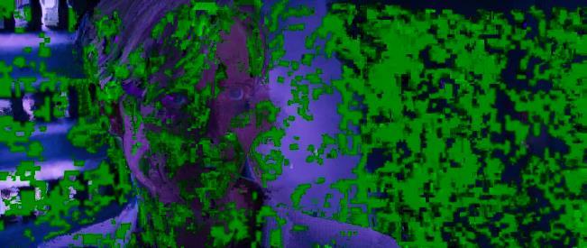
58 Most of the results we received were as expected. In the first scenario, since the bitrate was higher than the original, it was natural for the quality of the output video to be better. The PSNR ratio of our technique was 51.5dB, higher than the 48.7dB that the original VLC produced. A higher PSNR means less distortion, noise and freezes in the output video. Here we present to you pictures from the output video. On the left there are pictures from our technique and on the right from the original VLC. Figure 5.7: Screenshots from the outcomes of the first scenario Zervas Triantafyllos Page 58
59 Overall, both videos showed distortion with the original's output video having a little more than our technique. The original's video showed distortion especially in the middle of the transmission and at the end where our technique showed distortion only at the start of the video due to the fact that the bitrate was changing fast and the filters couldn't smooth the picture so fast. One negative disadvantage that appeared in both techniques is that the video had no continuity probably because of the weather conditions and other transmissions were happening during the transmission of the videos. Freezes in the video were happening so frequently using both techniques, so we can't say for sure that one technique will guarantee continuity over the other. The only thing that we can guarantee is that our technique can produce better picture in situations like this as shown by the bitrate and PSNR. After the execution of the second scenario, we gathered almost the same results as the first one regarding the PSNR. The PSNR ratio was almost the same in this situation as well but the difference this time was that the video had continuity and less freezes overall. Again the quality of the video regarding the output video from our technique was better in general and with less distortion. We received almost the same results from the original VLC where the only difference was that the outcome of the original had one or two more freezes where our technique had none. As for noise and distortion, again our technique showed distortion on the start of the transmission while the original had some distortion throughout the video. In the next page, we will present pictures from the outcome of both techniques in the second scenario. On the left are pictures from our technique and on the right from the original VLC. Zervas Triantafyllos Page 59


60 Figure 5.8: Screenshots from the outcomes of the second scenario Zervas Triantafyllos Page 60


61 The results from the third scenario were different from the previous two. This time the PSNR we collected from the original VLC was greater than the modified technique we proposed. We anticipated this since the encoding bitrate we used was lower than the bitrate the original VLC used during the transmission. Unfortunately, the PSNR cannot show the bad quality of the outcome video and that's why we will present pictures from the output videos. The PSNR value which represents our technique was 45.6dB while the original VLC's PSNR was approximately 48.7dB. Below you can see on the left the modified technique's results and on the right the original's. From the pictures it is clear that our technique outperformed the original. Figure 5.9: Screenshots from the outcomes of the third scenario Zervas Triantafyllos Page 61


62 During the second set of experiments, where the rate threshold was at 5.5Mbps, the network was more flexible and both techniques could improve their performance. The original VLC transmitted with a constant bitrate and had the same PSNR as the previous scenarios while our technique improved its PSNR from the previous set of experiments since the bitrate was no longer low and it rose up to 2.4Mbps. The output video's PSNR from our technique was close to the first and second scenario's value at 51.1dB. The video has performed almost the same as the second scenario as you can see from the pictures below. Figure 5.10: Screenshots from the second set of experiments Zervas Triantafyllos Page 62


63 As we explained at the third scenario and first set of experiments, this time again the original VLC produced a higher quality video again, as it is shown by the PSNR, something that is not accurate. Our technique needed two seconds to reconfigure the encoding bitrate while the original VLC kept the same bitrate. That resulted in a bad output video with lot of freezes and distortion while, on the other hand, our technique lowered the quality in order to keep the continuity, hence the lower PSNR. The PSNR from the modified technique was at approximately 48dB while the original VLC's video was at 48.8dB. Below you can see how well our technique was adapted to the network situations after the 15 second mark. In the output video from our technique, VLC needed 10 seconds to stabilize the picture while the original technique never did. Figure 5.11: Screenshots from the fourth scenario Zervas Triantafyllos Page 63


64 During the execution of the fifth scenario, it was an opportunity for us to observe how the two techniques will react to a sudden change of the rate that will only last 10 seconds. We believed that the original VLC will come back to normal easier since the rate was fixed at a low point but it needed more time. Although, the original's outcome had worse quality, our technique's outcome had more freezes but did not last for more than a couple of seconds. That is why the PSNR this time was higher for our technique at approximately 49.2dB while the original's output video was at 48.8dB. Our technique bounced back at 5 seconds but VLC got rid of distortion after 10 seconds. On the other hand, the original's outcome didn't have any freezes but the picture became normal after 20 seconds. Figure 5.12: Screenshots the fifth scenario Zervas Triantafyllos Page 64


65 The sixth scenario, as we mentioned before, really tested both techniques and showed how well they performed under bad and natural circumstances. Although under bad circumstances the PSNR of the original VLC was better than our technique's, the video was extremely bad. We can see that by the extremely high packet loss. The video was full of freezes and distortion as we will show you in the pictures below. On the contrary, our technique performed the same way as in the previous 1Mbps experiments and avoided major freezes and distortion. Since we lowered the quality, it was logical the PSNR to be approximately 39.4dB while the original's output PSNR was 48.7dB. Figure 5.13: Screenshots from the sixth scenario Zervas Triantafyllos Page 65


66 In the last set of experiments, the results of our technique were lower than the original VLC's. Since now the network could afford the encoding bitrate that the original VLC chose, the output quality was better than our technique and presented less problems on the outcome. Since the original's outcome video was encoded at a higher bitrate, the PSNR ratio was higher than our technique's output video PSNR, since the bitrate difference was almost 1Mbps. The PSNR ratio for the original's outcome was approximately 43.7dB while our technique had an average PSNR of 42.7dB. Although the quality was better, our technique did a great job and produced a good quality outcome. Figure 5.14: Screenshots from the second set of experiments Zervas Triantafyllos Page 66
RTP. Prof. C. Noronha RTP. Real-Time Transport Protocol RFC 1889
 RTP Real-Time Transport Protocol RFC 1889 1 What is RTP? Primary objective: stream continuous media over a best-effort packet-switched network in an interoperable way. Protocol requirements: Payload Type
Transporting Voice by Using IP
 Transporting Voice by Using IP Voice over UDP, not TCP Speech Small packets, 10 40 ms Occasional packet loss is not a catastrophe Delay-sensitive TCP: connection set-up, ack, retransmit delays 5 % packet
RTP: A Transport Protocol for Real-Time Applications
 RTP: A Transport Protocol for Real-Time Applications Provides end-to-end delivery services for data with real-time characteristics, such as interactive audio and video. Those services include payload type
Multimedia in the Internet
 Protocols for multimedia in the Internet Andrea Bianco Telecommunication Network Group firstname.lastname@polito.it http://www.telematica.polito.it/ > 4 4 3 < 2 Applications and protocol stack DNS Telnet
ΠΑΝΕΠΙΣΤΗΜΙΟ ΘΕΣΣΑΛΙΑΣ ΤΜΗΜΑ ΗΛΕΚΤΡΟΛΟΓΩΝ ΜΗΧΑΝΙΚΩΝ ΚΑΙ ΜΗΧΑΝΙΚΩΝ ΥΠΟΛΟΓΙΣΤΩΝ. Διπλωματική Εργασία
 ΠΑΝΕΠΙΣΤΗΜΙΟ ΘΕΣΣΑΛΙΑΣ ΤΜΗΜΑ ΗΛΕΚΤΡΟΛΟΓΩΝ ΜΗΧΑΝΙΚΩΝ ΚΑΙ ΜΗΧΑΝΙΚΩΝ ΥΠΟΛΟΓΙΣΤΩΝ Διπλωματική Εργασία Θέμα: Υλοποίηση και αξιολόγηση πρωτοκόλλων δικτύωσης με χρήση της OpenFlow τεχνολογίας Ραδουνισλής Αναστάσιος
CS519: Computer Networks. Lecture 9: May 03, 2004 Media over Internet
 : Computer Networks Lecture 9: May 03, 2004 Media over Internet Media over the Internet Media = Voice and Video Key characteristic of media: Realtime Which we ve chosen to define in terms of playback,
RTP/RTCP protocols. Introduction: What are RTP and RTCP?
 RTP/RTCP protocols Introduction: What are RTP and RTCP? The spread of computers, added to the availability of cheap audio/video computer hardware, and the availability of higher connection speeds have
4 rd class Department of Network College of IT- University of Babylon
 1. INTRODUCTION We can divide audio and video services into three broad categories: streaming stored audio/video, streaming live audio/video, and interactive audio/video. Streaming means a user can listen
On the Scalability of RTCP Based Network Tomography for IPTV Services. Ali C. Begen Colin Perkins Joerg Ott
 On the Scalability of RTCP Based Network Tomography for IPTV Services Ali C. Begen Colin Perkins Joerg Ott Content Distribution over IP Receivers Content Distributor Network A Transit Provider A Transit
in the Internet Andrea Bianco Telecommunication Network Group Application taxonomy
 Multimedia traffic support in the Internet Andrea Bianco Telecommunication Network Group firstname.lastname@polito.it http://www.telematica.polito.it/ Network Management and QoS Provisioning - 1 Application
Transport Protocols. ISO Defined Types of Network Service: rate and acceptable rate of signaled failures.
 Transport Protocols! Type A: ISO Defined Types of Network Service: Network connection with acceptable residual error rate and acceptable rate of signaled failures. - Reliable, sequencing network service
Digital Asset Management 5. Streaming multimedia
 Digital Asset Management 5. Streaming multimedia 2015-10-29 Keys of Streaming Media Algorithms (**) Standards (*****) Complete End-to-End systems (***) Research Frontiers(*) Streaming... Progressive streaming
CSCD 433/533 Advanced Networks Fall Lecture 14 RTSP and Transport Protocols/ RTP
 CSCD 433/533 Advanced Networks Fall 2012 Lecture 14 RTSP and Transport Protocols/ RTP 1 Topics Multimedia Player RTSP Review RTP Real Time Protocol Requirements for RTP RTP Details Applications that use
Multimedia Protocols. Foreleser: Carsten Griwodz Mai INF-3190: Multimedia Protocols
 Multimedia Protocols Foreleser: Carsten Griwodz Email: griff@ifi.uio.no 11. Mai 2006 1 INF-3190: Multimedia Protocols Media! Medium: "Thing in the middle! here: means to distribute and present information!
Transport protocols Introduction
 Transport protocols 12.1 Introduction All protocol suites have one or more transport protocols to mask the corresponding application protocols from the service provided by the different types of network
Lecture 14: Multimedia Communications
 Lecture 14: Multimedia Communications Prof. Shervin Shirmohammadi SITE, University of Ottawa Fall 2005 CEG 4183 14-1 Multimedia Characteristics Bandwidth Media has natural bitrate, not very flexible. Packet
Lecture 6: Internet Streaming Media
 Lecture 6: Internet Streaming Media A/Prof. Jian Zhang NICTA & CSE UNSW Dr. Reji Mathew EE&T UNSW COMP9519 Multimedia Systems S2 2010 jzhang@cse.unsw.edu.au Background So now you can code video (and audio)
RTP Profile for TCP Friendly Rate Control draft-ietf-avt-tfrc-profile-03.txt
 RTP Profile for TCP Friendly Rate Control draft-ietf-avt-tfrc-profile-03.txt Ladan Gharai (ladan@isi.edu).usc Information Sciences Institute November 11, 2004 61 IETF Washington DC Overview The RTP Profile
13. Internet Applications 최양희서울대학교컴퓨터공학부
 13. Internet Applications 최양희서울대학교컴퓨터공학부 Internet Applications Telnet File Transfer (FTP) E-mail (SMTP) Web (HTTP) Internet Telephony (SIP/SDP) Presence Multimedia (Audio/Video Broadcasting, AoD/VoD) Network
Popular protocols for serving media
 Popular protocols for serving media Network transmission control RTP Realtime Transmission Protocol RTCP Realtime Transmission Control Protocol Session control Real-Time Streaming Protocol (RTSP) Session
Outline. QoS routing in ad-hoc networks. Real-time traffic support. Classification of QoS approaches. QoS design choices
 Outline QoS routing in ad-hoc networks QoS in ad-hoc networks Classifiction of QoS approaches Instantiation in IEEE 802.11 The MAC protocol (recap) DCF, PCF and QoS support IEEE 802.11e: EDCF, HCF Streaming
Real-time Services BUPT/QMUL
 Real-time Services BUPT/QMUL 2015-06-02 Agenda Real-time services over Internet Real-time transport protocols RTP (Real-time Transport Protocol) RTCP (RTP Control Protocol) Multimedia signaling protocols
University of Thessaly, THESIS
 University of Thessaly, 2014-2015 DEPARTMENT OF ELECTRICAL AND COMPUTER ENGINEERING THESIS Title: Development of a framework for monitoring and measurement collection of networking resources of the NITOS
Real-Time Transport Protocol (RTP)
") Real-Time Transport Protocol (RTP) 1 2 RTP protocol goals mixers and translators control: awareness, QOS feedback media adaptation 3 RTP the big picture application media encapsulation RTP RTCP data UDP
Real-Time Transport Protocol (RTP) 1 2 RTP protocol goals mixers and translators control: awareness, QOS feedback media adaptation 3 RTP the big picture application media encapsulation RTP RTCP data UDP
Networking Applications
 Networking Dr. Ayman A. Abdel-Hamid College of Computing and Information Technology Arab Academy for Science & Technology and Maritime Transport Multimedia Multimedia 1 Outline Audio and Video Services
CS High Speed Networks. Dr.G.A.Sathish Kumar Professor EC
 CS2060 - High Speed Networks Dr.G.A.Sathish Kumar Professor EC UNIT V PROTOCOLS FOR QOS SUPPORT UNIT V PROTOCOLS FOR QOS SUPPORT RSVP Goals & Characteristics RSVP operations, Protocol Mechanisms Multi
RTP: A Transport Protocol for Real-Time Applications
 Internet Engineering Task Force INTERNET-DRAFT draft-ietf-avt-rtp-07.ps Audio-Video Transport WG Schulzrinne/Casner/Frederick/Jacobson GMD/ISI/Xerox/LBL March 21, 1995 Expires: 9/1/95 RTP: A Transport
Real-Time Protocol (RTP)
") Real-Time Protocol (RTP) Provides standard packet format for real-time application Typically runs over UDP Specifies header fields below Payload Type: 7 bits, providing 128 possible different types of
Real-Time Protocol (RTP) Provides standard packet format for real-time application Typically runs over UDP Specifies header fields below Payload Type: 7 bits, providing 128 possible different types of
Real-time Services BUPT/QMUL
 Real-time Services BUPT/QMUL 2017-05-27 Agenda Real-time services over Internet Real-time transport protocols RTP (Real-time Transport Protocol) RTCP (RTP Control Protocol) Multimedia signaling protocols
CS 218 F Nov 3 lecture: Streaming video/audio Adaptive encoding (eg, layered encoding) TCP friendliness. References:
 TCP friendliness. References:") CS 218 F 2003 Nov 3 lecture: Streaming video/audio Adaptive encoding (eg, layered encoding) TCP friendliness References: J. Padhye, V.Firoiu, D. Towsley, J. Kurose Modeling TCP Throughput: a Simple Model
CS 218 F 2003 Nov 3 lecture: Streaming video/audio Adaptive encoding (eg, layered encoding) TCP friendliness References: J. Padhye, V.Firoiu, D. Towsley, J. Kurose Modeling TCP Throughput: a Simple Model
Outline. Multimedia is different Real Time Protocol (RTP) Session Description Protocol (SDP) Session Initiation Protocol (SIP)
 Session Description Protocol (SDP) Session Initiation Protocol (SIP)") Outline Multimedia is different Real Time Protocol (RTP) Session Description Protocol (SDP) Session Initiation Protocol (SIP) Elastic vs. Inelastic Workloads Some applications adapt to network performance
Outline Multimedia is different Real Time Protocol (RTP) Session Description Protocol (SDP) Session Initiation Protocol (SIP) Elastic vs. Inelastic Workloads Some applications adapt to network performance
Provide a generic transport capabilities for real-time multimedia applications Supports both conversational and streaming applications
 Contents: Real-time Transport Protocol (RTP) Purpose Protocol Stack RTP Header Real-time Transport Control Protocol (RTCP) Voice over IP (VoIP) Motivation H.323 SIP VoIP Performance Tests Build-out Delay
Διπλωματική Εργασία. ερευνητική υποδομή του NITOS>> experimentation with NITOS facility>> Ζαμίχος Αλέξανδρος
 Πανεπιστήμιο Θεσσαλίας, 2014-2015 Τμήμα Ηλεκτρολόγων Μηχανικών & Μηχανικών Υπολογιστών Διπλωματική Εργασία Θέμα: >
ETSF10 Internet Protocols Transport Layer Protocols
 ETSF10 Internet Protocols Transport Layer Protocols 2012, Part 2, Lecture 2.2 Kaan Bür, Jens Andersson Transport Layer Protocols Special Topic: Quality of Service (QoS) [ed.4 ch.24.1+5-6] [ed.5 ch.30.1-2]
Voice in Packets: RTP, RTCP, Header Compression, Playout Algorithms, Terminal Requirements and Implementations
 Voice in Packets: RTP, RTCP, Header Compression, Playout Algorithms, Terminal Requirements and Implementations Jani Lakkakorpi Nokia Research Center P.O. Box 407 FIN-00045 NOKIA GROUP Finland jani.lakkakorpi@nokia.com
Multimedia Networking
 CMPT765/408 08-1 Multimedia Networking 1 Overview Multimedia Networking The note is mainly based on Chapter 7, Computer Networking, A Top-Down Approach Featuring the Internet (4th edition), by J.F. Kurose
Introduction to Networked Multimedia An Introduction to RTP p. 3 A Brief History of Audio/Video Networking p. 4 Early Packet Voice and Video
 Preface p. xi Acknowledgments p. xvii Introduction to Networked Multimedia An Introduction to RTP p. 3 A Brief History of Audio/Video Networking p. 4 Early Packet Voice and Video Experiments p. 4 Audio
Chapter 28. Multimedia
 Chapter 28. Multimedia 28-1 Internet Audio/Video Streaming stored audio/video refers to on-demand requests for compressed audio/video files Streaming live audio/video refers to the broadcasting of radio
陳懷恩博士助理教授兼所長國立宜蘭大學資訊工程研究所 TEL: # 255
 Introduction ti to VoIP 陳懷恩博士助理教授兼所長國立宜蘭大學資訊工程研究所 Email: wechen@niu.edu.tw TEL: 3-93574 # 55 Outline Introduction VoIP Call Tpyes VoIP Equipments Speech and Codecs Transport Protocols Real-time Transport
Kommunikationssysteme [KS]
![Kommunikationssysteme [KS]](/thumbs/86/93298659.jpg "Kommunikationssysteme [KS]") Kommunikationssysteme [KS] Dr.-Ing. Falko Dressler Computer Networks and Communication Systems Department of Computer Sciences University of Erlangen-Nürnberg http://www7.informatik.uni-erlangen.de/~dressler/
Kommunikationssysteme [KS] Dr.-Ing. Falko Dressler Computer Networks and Communication Systems Department of Computer Sciences University of Erlangen-Nürnberg http://www7.informatik.uni-erlangen.de/~dressler/
TSIN02 - Internetworking
 Lecture 7: Real-time Streaming Literature: Fouruzan ch. 28 RFC3550 (Real-time Protocol) RFC2327 (Session Description Protocol) RFC2326 (Real-time Streaming Protocol) Lecture 7: Real-time Streaming Goals:
Streaming (Multi)media
media") Streaming (Multi)media Overview POTS, IN SIP, H.323 Circuit Switched Networks Packet Switched Networks 1 POTS, IN SIP, H.323 Circuit Switched Networks Packet Switched Networks Circuit Switching Connection-oriented
Streaming (Multi)media Overview POTS, IN SIP, H.323 Circuit Switched Networks Packet Switched Networks 1 POTS, IN SIP, H.323 Circuit Switched Networks Packet Switched Networks Circuit Switching Connection-oriented
TSIN02 - Internetworking
 Lecture 7: Real-time Streaming Literature: Fouruzan ch. 28 RFC3550 (Real-time Protocol) RFC2327 (Session Description Protocol) RFC2326 (Real-time Streaming Protocol) 2004 Image Coding Group, Linköpings
RTP model.txt 5/8/2011
 Version 0.3 May 6, 2011 (1) Introduction This document provides recommendations and guidelines for RTP and RTCP in context of SIPREC. In order to communicate most effectively, Session Recording Client
Mohammad Hossein Manshaei 1393
 Mohammad Hossein Manshaei manshaei@gmail.com 1393 Voice and Video over IP Slides derived from those available on the Web site of the book Computer Networking, by Kurose and Ross, PEARSON 2 Multimedia networking:
ΠΑΝΕΠΙΣΤΗΜΙΟ ΘΕΣΣΑΛΙΑΣ
 ΠΑΝΕΠΙΣΤΗΜΙΟ ΘΕΣΣΑΛΙΑΣ ΠΟΛΥΤΕΧΝΙΚΗ ΣΧΟΛΗ ΤΜΗΜΑ ΜΗΧΑΝΙΚΩΝ ΗΛΕΚΤΡΟΝΙΚΩΝ ΥΠΟΛΟΓΙΣΤΩΝ ΤΗΛΕΠΙΚΟΙΝΩΝΙΩΝ ΚΑΙ ΔΙΚΤΥΩΝ Ανάπτυξη εφαρμογών σε έξυπνα κινητά τηλέφωνα για καταγραφή και μελέτη κίνησης σε εξωτερικούς
Cooperative caching in proxy-based wireless networks for multi-item queries
 ΠΑΝΕΠΙΣΤΗΜΙΟ ΘΕΣΣΑΛΙΑΣ ΤΜΗΜΑ ΗΛΕΚΤΡΟΛΟΓΩΝ ΜΗΧΑΝΙΚΩΝ ΚΑΙ ΜΗΧΑΝΙΚΩΝ ΥΠΟΛΟΓΙΣΤΩΝ Cooperative caching in proxy-based wireless networks for multi-item queries Διπλωματική Εργασία ΚΟΚΚΑΛΗΣ ΓΙΑΝΝΗΣ Βόλος, 2015
Transporting Voice by Using IP
 Transporting Voice by Using IP National Chi Nan University Quincy Wu Email: solomon@ipv6.club.tw 1 Outline Introduction Voice over IP RTP & SIP Conclusion 2 Digital Circuit Technology Developed by telephone
Recommended Readings
 Lecture 11: Media Adaptation Scalable Coding, Dealing with Errors Some slides, images were from http://ip.hhi.de/imagecom_g1/savce/index.htm and John G. Apostolopoulos http://www.mit.edu/~6.344/spring2004
RTP Protocol Transport of H.264 Video and MPEG I/II Layer 3 Audio
 RTP Protocol Transport of H.264 Video and MPEG I/II Layer 3 Audio Application Note: AN104 May 4, 2018 Cimarron Systems, LLC Copyright 2018 all rights reserved. Table of Contents Using the RTP Protocol
Multimedia networks. Additional references. Jargon. Analog to Digital (S5 4.3) KR: Kurose and Ross chapter 7 (KR3: 3 rd ed)
 KR: Kurose and Ross chapter 7 (KR3: 3 rd ed)") Additional references Multimedia networks KR: Kurose and Ross chapter 7 (KR3: 3 rd ed) C4: Douglas Comer, Internetworking with TCP/IP Vol 1: Principles, Protocols and Architecture 4 th ed, Prentice-Hall
Additional references Multimedia networks KR: Kurose and Ross chapter 7 (KR3: 3 rd ed) C4: Douglas Comer, Internetworking with TCP/IP Vol 1: Principles, Protocols and Architecture 4 th ed, Prentice-Hall
Latency and Loss Requirements! Receiver-side Buffering! Dealing with Loss! Loss Recovery!
 Cumulative data! Latency and Loss Requirements! Fundamental characteristics of multimedia applications:! Typically delay sensitive!! live audio < 150 msec end-to-end delay is not perceptible!! 150-400
6.1 Internet Transport Layer Architecture 6.2 UDP (User Datagram Protocol) 6.3 TCP (Transmission Control Protocol) 6. Transport Layer 6-1
 6.3 TCP (Transmission Control Protocol) 6. Transport Layer 6-1") 6. Transport Layer 6.1 Internet Transport Layer Architecture 6.2 UDP (User Datagram Protocol) 6.3 TCP (Transmission Control Protocol) 6. Transport Layer 6-1 6.1 Internet Transport Layer Architecture The
6. Transport Layer 6.1 Internet Transport Layer Architecture 6.2 UDP (User Datagram Protocol) 6.3 TCP (Transmission Control Protocol) 6. Transport Layer 6-1 6.1 Internet Transport Layer Architecture The
EEC-682/782 Computer Networks I
 EEC-682/782 Computer Networks I Lecture 16 Wenbing Zhao w.zhao1@csuohio.edu http://academic.csuohio.edu/zhao_w/teaching/eec682.htm (Lecture nodes are based on materials supplied by Dr. Louise Moser at
Congestion Feedback in RTCP
 Congestion Feedback in RTCP Colin Perkins Presentation given to IETF RMCAT working group on 19 July 2017 This work is licensed under the Creative Commons Attribution-NoDerivatives 4.0 International License.
AIMD (additive-increase, multiplicative-decrease),
,") AW001-PerkinsIX 5/14/03 2:01 PM Page 397 INDEX A ACK (acknowledgement) Use with RTP retransmission, 277 279 Use with TCP 292 294 ACM (Association for Computing Machinery), 26 Active content, security of,
AW001-PerkinsIX 5/14/03 2:01 PM Page 397 INDEX A ACK (acknowledgement) Use with RTP retransmission, 277 279 Use with TCP 292 294 ACM (Association for Computing Machinery), 26 Active content, security of,
ECE 650 Systems Programming & Engineering. Spring 2018
 ECE 650 Systems Programming & Engineering Spring 2018 Networking Transport Layer Tyler Bletsch Duke University Slides are adapted from Brian Rogers (Duke) TCP/IP Model 2 Transport Layer Problem solved:
Multimedia Networking
 Multimedia Networking #2 Multimedia Networking Semester Ganjil 2012 PTIIK Universitas Brawijaya #2 Multimedia Applications 1 Schedule of Class Meeting 1. Introduction 2. Applications of MN 3. Requirements
Multimedia! 23/03/18. Part 3: Lecture 3! Content and multimedia! Internet traffic!
 Part 3: Lecture 3 Content and multimedia Internet traffic Multimedia How can multimedia be transmitted? Interactive/real-time Streaming 1 Voice over IP Interactive multimedia Voice and multimedia sessions
Part 3: Lecture 3! Content and multimedia!
 Part 3: Lecture 3! Content and multimedia! Internet traffic! Multimedia! How can multimedia be transmitted?! Interactive/real-time! Streaming! Interactive multimedia! Voice over IP! Voice and multimedia
ITTC Communication Networks The University of Kansas EECS 780 Multimedia and Session Control
 Communication Networks The University of Kansas EECS 780 Multimedia and Session Control James P.G. Sterbenz Department of Electrical Engineering & Computer Science Information Technology & Telecommunications
Chapter 7. The Transport Layer
 Chapter 7 The Transport Layer 1 2 3 4 5 6 7 8 9 10 11 Addressing TSAPs, NSAPs and transport connections. 12 For rarely used processes, the initial connection protocol is used. A special process server,
Multimedia Applications. Classification of Applications. Transport and Network Layer
 Chapter 2: Representation of Multimedia Data Chapter 3: Multimedia Systems Communication Aspects and Services Multimedia Applications and Communication Protocols Quality of Service and Resource Management
QoE Characterization for Video-On-Demand Services in 4G WiMAX Networks
 QoE Characterization for Video-On-Demand Services in 4G WiMAX Networks Amitabha Ghosh IBM India Research Laboratory Department of Electrical Engineering University of Southern California, Los Angeles http://anrg.usc.edu/~amitabhg
MITIGATING THE EFFECT OF PACKET LOSSES ON REAL-TIME VIDEO STREAMING USING PSNR AS VIDEO QUALITY ASSESSMENT METRIC ABSTRACT
 MITIGATING THE EFFECT OF PACKET LOSSES ON REAL-TIME VIDEO STREAMING USING PSNR AS VIDEO QUALITY ASSESSMENT METRIC Anietie Bassey, Kufre M. Udofia & Mfonobong C. Uko Department of Electrical/Electronic
Request for Comments: dynamicsoft H. Schulzrinne Columbia University August 2001
 Network Working Group Request for Comments: 3158 Category: Informational C. Perkins USC/ISI J. Rosenberg dynamicsoft H. Schulzrinne Columbia University August 2001 RTP Testing Strategies Status of this
Higher layer protocols
 ETSF05/ETSF10 Internet Protocols Higher layer protocols DHCP DNS Real time applications RTP The hen or the egg? DHCP IP addr. IP DNS TCP UDP ETSF05/ETSF10 - Internet Protocols 2 What to configure IP address
Voice in Packets: RTP, RTCP, Header Compression, Playout Algorithms, Terminal Requirements and Implementations
 Voice in Packets: RTP, RTCP, Header Compression, Playout Algorithms, Terminal Requirements and Implementations Jani Lakkakorpi Nokia Research Center P.O. Box 407 FIN-00045 NOKIA GROUP Finland jani.lakkakorpi@nokia.com
Congestion Manager. Nick Feamster Computer Networks. M.I.T. Laboratory for Computer Science. October 24, 2001
 Congestion Manager Nick Feamster M.I.T. Laboratory for Computer Science 6.829 Computer Networks October 24, 2001 Outline Motivation (problem CM solves?) Sharing info on concurrent flows Enable application
DISTRIBUTED NETWORK COMMUNICATION FOR AN OLFACTORY ROBOT ABSTRACT
 DISTRIBUTED NETWORK COMMUNICATION FOR AN OLFACTORY ROBOT NSF Summer Undergraduate Fellowship in Sensor Technologies Jiong Shen (EECS) - University of California, Berkeley Advisor: Professor Dan Lee ABSTRACT
Multimedia Networking
 Multimedia Networking 1 Multimedia, Quality of Service (QoS): What is it? Multimedia applications: Network audio and video ( continuous media ) QoS Network provides application with level of performance
Achieving Low-Latency Streaming At Scale
 Achieving Low-Latency Streaming At Scale Founded in 2005, Wowza offers a complete portfolio to power today s video streaming ecosystem from encoding to delivery. Wowza provides both software and managed
Overview. Slide. Special Module on Media Processing and Communication
 Overview Review of last class Protocol stack for multimedia services Real-time transport protocol (RTP) RTP control protocol (RTCP) Real-time streaming protocol (RTSP) SIP Special Module on Media Processing
Multimedia networking: outline
 Multimedia networking: outline 7.1 multimedia networking applications 7.2 streaming stored video 7.3 voice-over-ip 7.4 protocols for real-time conversational applications: RTP, SIP 7.5 network support
EEC-484/584 Computer Networks. Lecture 16. Wenbing Zhao
 EEC-484/584 Computer Networks Lecture 16 wenbing@ieee.org (Lecture nodes are based on materials supplied by Dr. Louise Moser at UCSB and Prentice-Hall) Outline 2 Review Services provided by transport layer
RECOMMENDATION ITU-R BT.1720 *
 Rec. ITU-R BT.1720 1 RECOMMENDATION ITU-R BT.1720 * Quality of service ranking and measurement methods for digital video broadcasting services delivered over broadband Internet protocol networks (Question
Mul$media Networking. #5 Real- Time Transport Protocol Semester Ganjil 2012 PTIIK Universitas Brawijaya
 Mul$media Networking #5 Real- Time Transport Protocol Semester Ganjil 2012 PTIIK Universitas Brawijaya Schedule of Class Mee$ng 1. Introduc$on 2. Applica$ons of MN 3. Requirements of MN 4. Coding and Compression
Paper solution Subject: Computer Networks (TE Computer pattern) Marks : 30 Date: 5/2/2015
 Marks : 30 Date: 5/2/2015") Paper solution Subject: Computer Networks (TE Computer- 2012 pattern) Marks : 30 Date: 5/2/2015 Q1 a) What is difference between persistent and non persistent HTTP? Also Explain HTTP message format. [6]
Paper solution Subject: Computer Networks (TE Computer- 2012 pattern) Marks : 30 Date: 5/2/2015 Q1 a) What is difference between persistent and non persistent HTTP? Also Explain HTTP message format. [6]
Computer Networks. Wenzhong Li. Nanjing University
 Computer Networks Wenzhong Li Nanjing University 1 Chapter 5. End-to-End Protocols Transport Services and Mechanisms User Datagram Protocol (UDP) Transmission Control Protocol (TCP) TCP Congestion Control
Chapter 9. Multimedia Networking. Computer Networking: A Top Down Approach
 Chapter 9 Multimedia Networking A note on the use of these Powerpoint slides: We re making these slides freely available to all (faculty, students, readers). They re in PowerPoint form so you see the animations;
Medical Sensor Application Framework Based on IMS/SIP Platform
 Medical Sensor Application Framework Based on IMS/SIP Platform I. Markota, I. Ćubić Research & Development Centre, Ericsson Nikola Tesla d.d. Poljička cesta 39, 21000 Split, Croatia Phone: +38521 305 656,
Video Streaming in Wireless Environments
 Video Streaming in Wireless Environments Manoj Kumar C Advisor Prof. Sridhar Iyer Kanwal Rekhi School of Information Technology Indian Institute of Technology, Bombay Mumbai 1 Motivation Refers to real-time
Lecture 9: Media over IP
 Lecture 9: Media over IP These slides are adapted from the slides provided by the authors of the book (to the right), available from the publisher s website. Computer Networking: A Top Down Approach 5
Troubleshooting Packet Loss. Steven van Houttum
 Troubleshooting Packet Loss Steven van Houttum INTRODUCTION Steven van Houttum Consultant/Trainer MVP Office Server & Services (Skype for Business) TROUBLESHOOTING PACKET LOSS, IS IT REALLY THE NETWORK?
Extensions to RTP to support Mobile Networking: Brown, Singh 2 within the cell. In our proposed architecture [3], we add a third level to this hierarc
![Extensions to RTP to support Mobile Networking: Brown, Singh 2 within the cell. In our proposed architecture [3], we add a third level to this hierarc](/thumbs/88/114904400.jpg "Extensions to RTP to support Mobile Networking: Brown, Singh 2 within the cell. In our proposed architecture [3], we add a third level to this hierarc") Extensions to RTP to support Mobile Networking Kevin Brown Suresh Singh Department of Computer Science Department of Computer Science University of South Carolina Department of South Carolina Columbia,
Extensions to RTP to support Mobile Networking Kevin Brown Suresh Singh Department of Computer Science Department of Computer Science University of South Carolina Department of South Carolina Columbia,
Multimedia Communications
 Multimedia Communications Prof. Pallapa Venkataram, Electrical Communication Engineering, Indian Institute of Science, Bangalore 560012, India Objectives To know the networking evolution. To understand
Lecture-4. TCP/IP-Overview:
 Lecture-4 TCP/IP-Overview: The history goes back to ARPANET a research network sponsored by DoD US Govt. It eventually connected hundreds of universities and govt installations, using leased telephone
Real-Time Course. Video Streaming Over network. June Peter van der TU/e Computer Science, System Architecture and Networking
 Real-Time Course Video Streaming Over network 1 Home network example Internet Internet Internet in Ethernet switch 2 QoS chains Quality of video Size of video bit/s network Quality of network Bandwidth,
Video Streaming and Media Session Protocols
 Video Streaming and Media Session Protocols 1 Streaming Stored Multimedia Stored media streaming File containing digitized audio / video Stored at source Transmitted to client Streaming Client playout
File transfer. Internet Applications (FTP,WWW, ) Connections. Data connections
 Connections. Data connections") File transfer Internet Applications (FTP,WWW, Email) File transfer protocol (FTP) is used to transfer files from one host to another Handles all sorts of data files Handles different conventions used in
File transfer Internet Applications (FTP,WWW, Email) File transfer protocol (FTP) is used to transfer files from one host to another Handles all sorts of data files Handles different conventions used in
Multimedia Networking
 Multimedia Networking Raj Jain Washington University in Saint Louis Saint Louis, MO 63130 Jain@wustl.edu Audio/Video recordings of this lecture are available on-line at: http://www.cse.wustl.edu/~jain/cse473-09/
UNIVERSITY OF OSLO Department of informatics. Investigating the limitations of video stream scheduling in the Internet. Master thesis.
 UNIVERSITY OF OSLO Department of informatics Investigating the limitations of video stream scheduling in the Internet Master thesis Espen Jacobsen May, 2009 Investigating the limitations of video stream
RTCP Feedback for Congestion Control in Interactive Multimedia Conferences draft-ietf-rmcat-rtp-cc-feedback-03. Colin Perkins
 RTCP Feedback for Congestion Control in Interactive Multimedia Conferences draft-ietf-rmcat-rtp-cc-feedback-03 Colin Perkins RTCP feedback timing can we report often enough? Congestion control requires
Internet Streaming Media. Reji Mathew NICTA & CSE UNSW COMP9519 Multimedia Systems S2 2006
 Internet Streaming Media Reji Mathew NICTA & CSE UNSW COMP9519 Multimedia Systems S2 2006 Multimedia Streaming UDP preferred for streaming System Overview Protocol stack Protocols RTP + RTCP SDP RTSP SIP
Request for Comments: 5109 December 2007 Obsoletes: 2733, 3009 Category: Standards Track. RTP Payload Format for Generic Forward Error Correction
 Network Working Group A. Li, Ed. Request for Comments: 5109 December 2007 Obsoletes: 2733, 3009 Category: Standards Track RTP Payload Format for Generic Forward Error Correction Status of This Memo This
2 RTP Encapsulation and its Application in NS-2 Simulation
 3rd International Conference on Multimedia Technology(ICMT 2013) RTP Encapsulation for Scalable Video Stream and its Application in NS-2 Simulation Zhou Ying, Zhang Jihong, Liu Wei Abstract. Real-time
CS 4390 Computer Networks. Transport Services and Protocols
 CS 4390 Computer Networks UT D data Session 07 Transport Layer Overview and UDP Adapted from Computer Networking a Top-Down Approach 1996-2012 by J.F Kurose and K.W. Ross, All Rights Reserved Transport
INSE 7110 Winter 2009 Value Added Services Engineering in Next Generation Networks Week #2. Roch H. Glitho- Ericsson/Concordia University
 INSE 7110 Winter 2009 Value Added Services Engineering in Next Generation Networks Week #2 1 Outline 1. Basics 2. Media Handling 3. Quality of Service (QoS) 2 Basics - Definitions - History - Standards.
Internet Streaming Media. Reji Mathew NICTA & CSE UNSW COMP9519 Multimedia Systems S2 2007
 Internet Streaming Media Reji Mathew NICTA & CSE UNSW COMP9519 Multimedia Systems S2 2007 Multimedia Streaming UDP preferred for streaming System Overview Protocol stack Protocols RTP + RTCP SDP RTSP SIP
Computer Networks and Data Systems
 Computer Networks and Data Systems Transport Layer TDC463 Winter 2011/12 John Kristoff - DePaul University 1 Why a transport layer? IP gives us end-to-end connectivity doesn't it? Why, or why not, more