Gateway configuration manual DMX - KNX TP EK-BK1-TP
|
|
|
- Scot Holland
- 6 years ago
- Views:
Transcription

1 DMX - KNX TP EK-BK1-TP
2 Indice Scope of the document Product description Main functions Technical data Supply System requirements for configuration software Certifications Switching, display and connection elements Configuration and commissioning DMX protocol general informations Configuration software Creating a new project or modifying a saved project Software Options Communication parameters KNX communication object configuration DMX default value configuration Configuration update Warning Other information SBS S.p.A. All rights reserved Page 2
3 Scope of the document This document describes the gateway (protocol converter) DMX KNX TP. The gateway finds its ideal applicaton in the integration of DMX devices over a RS485 serial network in a KNX-based automation system for homes and buildings. This product belongs to a broad line of ekinex gateways designed to meet the needs for integration of the building automation most widely used protocols, based on serial, Ethernet or proprietary infrastructures. For further informations about the available technical solutions, please visit 1 Product description The DMX ekinex EK-BK1-TP gateway è un apparecchio KNX modulare per montaggio a quadro. is a KNX modular unit for panel mounting. It allows you to exchange informations with one or more slave devices over a RS485 differential serial network through DMX protocol. The ekinex gateway acts as DMX master. The informations exchanged over the DMX network are updated over the KNX network by means of a twisted pair (TP) communication cable. The device manges a one-way data stream: up to 12 bytes of KNX data are defined, each one associated with a device over the DMX network. The gateway converts the data coming from KNX master and writes its value on the corresponding DMX device. Configuration is performed through a PC application software which communicates through the integrated Ethernet port. The application software CGEKBK1TP is available for download at SBS S.p.A. All rights reserved Page 3
4 1.1 Main functions The gateway acts as a unidirectional protocol converter: the KNX master writes up to 512 bytes on as many DMX devices. KNX side: up to byte communication objects are defined. Each object is converted by the gateway to a value between 0 and 256, which is sent to the corresponding DMX device. 1.2 Technical data Characteristic Power supply Power Absorption Application area Environmental conditions Programming elements Display elements Configuration elements Safety class Value 8 24 Vac Vdc At 24 Vdc: 3,5 VA dry indoor environment Operating temperature: C Stock temperature: C Transportation temperature: C Relative humidity: 93% non-condensing 1 pushbutton and 1 LED (red) on the front 4 status LEDs + 1 Ethernet connector LED 2 1-way microswitches Microswitch A: OFF normal mode; ON Boot mode Microswitch B: OFF terminaton resistance not inserted; ON termination resistance (120 ) inserted between RT+ ad RT- on the RS485 port. II Installation 35 mm DIN rail (according to EN 60529) Protection degree IP20 Dimensions (WxHxD) Connector Communication port Baud rate Communication port Power supply Current absorption from bus 82 x 75 x 35 mm Ethernet interface (IEEE 802.3) RJ45, minimum cable category: 5E DMX interface RS485, electrically isolated from power supply and KNX communication port 250 kbaud KNX TP interface KNX TP (twisted pair), 9600 baud, electrically isolated from power supply and RS485 communication port SELV 30 Vdc through bus KNX < 13 ma SBS S.p.A. All rights reserved Page 4
5 1.3 Supply The supply includes the device and terminal blocks to connect to the KNX bus. An instruction sheet is also supplied within the package. 1.4 System requirements for configuration software Configuration and commissioning of the ekinex gateway must be performed using the application program CGEKBK1TP, available for download at The PC where the application program is installed must meet the following requirements: Desktop o laptop PC with Ethernet IEEE port. 32/64 bit operating system, Microsoft Windows XP, 7, 8.0, 8.1 e 10. i.net Framework 4.0 system library installation is required. 1.5 Certifications Compliance with the European directives is certified by the CE symbol on the product label and on the documentation. SBS S.p.A. All rights reserved Page 5
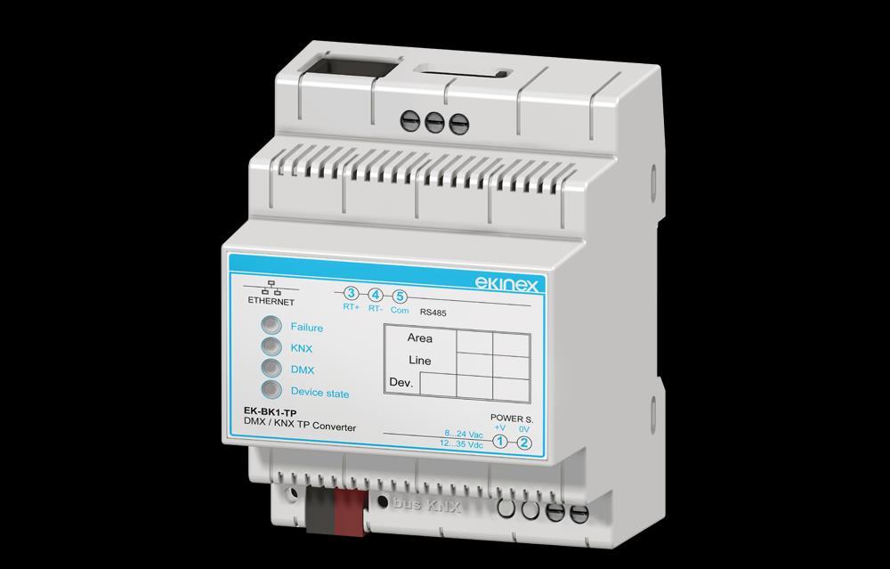
6 2 Switching, display and connection elements The device is equipped with a pushbutton and a KNX programming LED, with a status LED and terminal blocks for KNX and RS485 network connection. A port for RJ45 connector for device configuration via Ethernet as well as two 1-way microswitches are also present. 7 ON ETHERNET Com RT- RT+ RS Failure KNX DMX Device state EK-BK1-TP DMX / KNX TP Converter Area Line Dev. POWER S. +V 0V Vac Vdc ON Figure 1 - Switching, display and connection elements 1) KNX bus line terminal blocks 2) KNX programming pushbutton 3) KNX programming LED 4) Power supply terminal blocks 5) 1-way microswitch A 6) Ethernet port 7) Ethernet port LED 8) Device satus LED 9) DMX communication LED 10) KNX communication LED 11) Device error LED 12) RS485 serial line terminal blocks 13) 1-way microswitch B SBS S.p.A. All rights reserved Page 6
7 Command elements Pushbutton that switches between normal mode and KNX physical address programming. 1-way microswitches A - OFF: normal mode active. ON: Boot mode active B - OFF: open. ON: RS485 line termination inserted (120 termination resistance in parallel between RT+ and RT-) Display elements The device can run according to two operating modes: Normal mode (configuration loaded, DMX and KNX communication running) and Boot mode (no configuration or still loading configuration). LED Normal mode Boot mode Green LED (8) Device status Slow blinking (~1 Hz) ON: device on OFF: device off Yellow LED (9) Modbus communication Yellow LED (10) KNX communication Yellow LED (11) Device error Green LED (7) Ethernet port Red LED (3) KNX programming Blinks when a frame is received on the RS485 port. Blinks when a frame is received. ON: at least one DMX request did not get a correct answer OFF: no error ON: Ethernet connector plugged OFF: Ethernet connector unplugged ON: physical address programming mode on OFF: physical address programming mode off Fast blinking: no configuration Very slow blinking (~0,5 Hz): loading configuration. Fast blinking: no configuration Very slow blinking (~0,5 Hz): loading configuration. Fast blinking: no configuration Very slow blinking (~0,5 Hz): loading configuration. ON: Ethernet connector plugged OFF: Ethernet connector unplugged Fast blinking: no configuration Very slow blinking (~0,5 Hz): loading configuration. i In the current version of the device, both KNX physical address programming and configuration download must be performed through the configuration program: for KNX physical address please refer to Communication parameters paragraph, ID Device parameter. SBS S.p.A. All rights reserved Page 7
8 3 Configuration and commissioning The device configuration requires the following tools: The documentation of the DMX products CGEKBK1TP application software to properly configure the gateway Knowledge of the ETS automation project, with particular attention to communication objects and group addresses passing on the bus during the multicast communication between sensors and actuators. i Configuration and commissioning of the ekinex gateway require specialized skills about KNX networks and knowledge of the specific ETS automation project. In order to acquire such skills, it is essential to attend trainings and workshops organized at KNX-certified training centers. For further information: SBS S.p.A. All rights reserved Page 8
9 4 DMX protocol general informations DMX512, also known as DMX (Digital MultipleX), is a digital communication standard used primarily to control lighting in the entertainment business. It is typically implemented in a unidirectional way and it is based on RS-485 physical protocol. The protocol is essentially composed of a unidirectional serial string generated by a master device (in this case the ekinex gateway, which interprets and converts the incoming information from a KNX master), whose information can control up to 512 remote units (slaves) connected in cascade. Each remote unit is controlled by a data composed of eight bits (one byte), which contains the information that allows to obtain 256 possible levels. The transmission is asynchronous. Each bit sent over the network has a duration of 4 microseconds: the transmission speed is then 250 Kbps. The transmission starts with a BREAK, a string composed of a minimum of 22 bits at a low level, for a total duration of 88 microseconds. The duration of the BREAK can also be slightly higher: the protocol provides for a maximum duration of one second (though, especially if you send all 512 control bytes, it is recommended that the BREAK does not exceed 120 microseconds). Then the protocol sends a MAB (Mark After Break), composed of two high bits, for a total time of 8 microseconds. At this point of the protocol is ready to send the first frame (data 0) that is used as a Start Code (SC) and whose value is also zero. Each frame consists of a start bit (low level), data (CD, Channel Data by 8 bits, or one byte) and two stop bit (high level). The frame 0 contains no information, while the following 512 frames contain, in order, the levels which will be assigned to the controlled devices, from 1 to 512. Between consecutive frames a MTBF (Mark Time Between Frames) can be inserted, whose value must be between 0 and 1 second. Once the transmission of the data packet is done, a MTBP (Mark Time Between Packets) may be provided, whose value must be between 0 and 1 second. All receivers (slaves) are identified by a specific code between 1 and 512 set by a microswitch; each device has also a counter synchronized with the DMX512 Start Code string. When the counter identifies the frame corresponding to the code set, the data is stored inside the receiver and used to drive the slave. In a dimmable lamp, for example, if the byte contains the data 127 the lamp will light up to 50%, if 255 the lamp will be fully illuminated whilst if 0 the lamp will be switched off completely. SBS S.p.A. All rights reserved Page 9
; KNX network: communication objects definition and relative group addresses to be acquired; KNX network: communication objects definition and")

10 5 Configuration software The ekinex configuration software CG-EK-BK1-TP allows you to perform the following operations: Selection of physical address of the device over the KNX TP network; Selection of Ethernet parameters (for configuration download only); KNX network: communication objects definition and relative group addresses to be acquired; KNX network: communication objects definition and relative group addresses to be sent over the KNX network; DMX network: default values definition; Firmware and/or configuration update. The application program consists in multiple modal windows called forms : each form must be closed before accessing the following form. The buttons on the main form (see Figure 2 Main form of the application program) are ordered according to the proper sequence to follow in order to perform a correct configuration. Figure 2 Main form of the application program Starting from the main form, by accessing the About... window, you can check the current version of the installed program. Figure 3 About form i Please visit the section about communication gateways on in order to check the current version of the application program and download the latest version. SBS S.p.A. All rights reserved Page 10
: the configuration files are stored on the hard drive in XML format.")
\Ekinex\Compositor_CG-EK-BK1-TP\Projects.")
11 5.1 Creating a new project or modifying a saved project The application program allows you to create a new configuration or open an existing one using the buttons called New Configuration and Open Configuration (see Figure 2 Main form of the application program): the configuration files are stored on the hard drive in XML format. Figure 4 Create new configuration form Figure 5 Open configuration form i In order to duplicate an existing project, you must find the project folder containing the XML files and copy them in a new folder. Project files can be found by the following path: C:\Program Files(x86)\Ekinex\Compositor_CG-EK-BK1-TP\Projects. Once the project has been duplicated, simply restart the application program and open the form Open configuration (see Figure 6 - Open configuration form): you will see the name of the duplicated project in the list of available configurations. SBS S.p.A. All rights reserved Page 11

12 5.2 Software Options The Software Options form allows you to select a different language for the application program. Figure 6 Options form, Language tab SBS S.p.A. All rights reserved Page 12

13 5.3 Communication parameters In this section we define the basic communication parameters for the KNX TP network, for the DMX network and for Ethernet connection. Ethernet connection is required in order to perform the configuration update on the device. Figure 8 Set communication form You can access the form by pressing the Set Communication button in the main form (see Figure 2 Main form of the application program). Description of fields in Set communication form. Parameter name Values Description KNX Type ID Device DMX KNX TP Type of connection used for KNX communication. The parameter has a constant value KNX TP. The device supports KNX communicaton over a twisted pair communication cable. This parameter identifies the physical address assigned to the KNX device. The format requires the use of a dot. as a separator beween the 3 fields: area, line and device address. Here are the conventions used for physical addressing and the values used for each field: Area field: = 0 reserved for backbone, values [1...15] Line field: = 0 reserved for main line, values [1...15] Device address field: = 0 reserved for coupler, values [ ], range [1..64] for devices belonging to the line, above 64 for device belonging to extensions or other segments of the line. Example: 1.3.5: Area = 1; Line = 3; Device address = 5. Channel number Number of devices configured over the DMX network (up to 512) Ethernet IP ADDRESS SUBNET Mask GATEWAY IP Address (4-octet format) assigned to the device. Each octet is set in an Edit box. Default IP Address is: This is the address assigned to the device before the first configuration or after a complete restore. Subnet mask assigned to the device. Gateway address used for Ethernet communication. The gateway can be enabled or disabled through the control check-box placed at the right side of the field. SBS S.p.A. All rights reserved Page 13
14 i Please refer to the technical documentation of the slave device in order to set the correct parameters of the serial communication. Incompatible values of these parameters may prevent the correct exchange of frames. SBS S.p.A. All rights reserved Page 14
. Figure 9 KNX Set Access form The form contains a configurable grid.")
15 5.4 KNX communication object configuration In this section we define communication objects sent or acquired over the KNX network. You can access the form by pressing the KNX Access button in the main form (see Figure 2 Application program main form). Figure 9 KNX Set Access form The form contains a configurable grid. Each record allows you to assign the properties for each communication object exchanged over the KNX network. In order to make the management of a significant number of data easier, after selecting a record it is possible to delete it from the project, insert a new record in a specific position and perform copy/paste of a previously configured record. Description of fields in KNX Set Access form Field name Values Description N Enable Source Address Dest/Group Priority Format Extended checked / unchecked System/ Urgent / Normal / Low None / Swap16 / Swap32 / Swap All / Int to Float / Float to Int / Float 16 to Float 32 checked / unchecked Progressive number of the configuration record Configuration record enabling. If a record is disabled, the corresponding data points will not be acquired or changed over the KNX bus Through this field you can acquire datapoints of all lines over the KNX bus (0.0.0 value) or you can select one specific line (e.g ) or a single device identified by a specific physical address (e.g ). A Group Address (2-level, 3-level or free structure) or a Physical Address can be set. In case of a group address the fields must be separated through a /, while in case of physical address the separator will be a.. KNX frames priority. In multicast communication (exchange of frames from/to group addresses), the default priority is Low. Since only 1-byte values can be exchanged, the only admissible value is none. Enables extended frame format for KNX communication (cemi = Common Extended Message Interface) ReTest checked / unchecked Enables the re-send of a frame in case of wrong response message OnTimer Poll Time Position Bit Mode Length Mnemonic checked / unchecked Value in range [0 1439] No / 0 / 1 / 2 / 3 / 4 / 5 / 6 / 7 Event which enables the cyclical sending of command frames over the KNX bus. Cyclic poll time (in ms) when OnTimer event is enabled. Posizione del primo byte nel buffer di memoria interna di appoggio in cui viene memorizzato un dato. Position, inside the first byte of the internal support memory buffer, where a 1-bit data is stored. Size (in number of bytes) of the data stored inside the internal memory. Text to comment the record and/or the datapoint over the KNX bus. SBS S.p.A. All rights reserved Page 15

16 5.5 DMX default value configuration In this section we define the default values associated with the DMX devices. The default value is the value acquired by the channels associated to the DMX devices when the ekinex gateway is powered up. Figura 10 - Form DMX Default Value Description of fields in DMX Default Value form Field name Values Description Channel Device identification number Default value Default (power up) value Mnemonic Text to comment the register read over the DMX network. SBS S.p.A. All rights reserved Page 16
. There can be 2 possible update sequences, the first in case the IP address assigned to the device is unknown, the second in case the IP address is known.")
 to ON position Power on the device Connect PC and device by means of an Ethernet cable.")
17 5.6 Configuration update The implemented configuration and possibly the updated firmware can be downloaded by pressing the Update Device button in the main form of the application program (see Figure 2 Main form of the application program). There can be 2 possible update sequences, the first in case the IP address assigned to the device is unknown, the second in case the IP address is known. Figure 12 - Update configuration form Figure 13 - Download options form Sequence to follow in case of unassigned or unknown IP address: Power off the device Set the 1-way microswitch A (see Figure 1 Switching, display and connection elements) to ON position Power on the device Connect PC and device by means of an Ethernet cable. Make sure that the PC s network parameters are consistent with the IP address assigned to the device in Boot Mode Otherwise, change the PC s network settings Write the IP address inside the Update Configuration form (see Figure 12 Update configuration form) Press Ping button; if you correctly applied the procedure, the text Device found! will appear Press Next button Select the desired options (see Figure 13 Download options form): firmware update, configuration update or both Press Execute update firmware button When all operations are completed (see Figure 14 Update in progress) shut down the device Set the 1-way microswitch A (see Figure 1 Switching, display and connection elements) to OFF position Power on the device SBS S.p.A. All rights reserved Page 17

18 If the sequence is successful, this means that firmware and/or configuration has been correctly downloaded on the device. Figure 14 - Update in progress Sequence to follow in case of known IP address: Power on the device with PC and device connected by means of an Ethernet cable Provide the device IP address (see Figure 12 Update configuration form). Make sure that the PC s network parameters are consistent with the IP address assigned to the device. Otherwise, change the PC s network settings Press Ping button; if you correctly applied the procedure, the text Device found! will appear (see Figure 12 Update configuration form) Press Next button (see Figure 12 Update configuration form) Select the desired options (see Figure 13 Download options form): firmware update, configuration update or both Press Execute update firmware button When all operations are completed (see Figure 14 Update in progress) the device automatically switches back to Normal mode. If the sequence is successful, this means that firmware and/or configuration has been correctly downloaded on the device. i It is recommended to update the firmware when a new version of the application program is installed or when configuring the device for the first time. In case the update procedure goes into PROTECTION mode (see Figure 15 Update error, Protection mode), you may want to check the following: Figure 15 Update error, Protection mode SBS S.p.A. All rights reserved Page 18
19 Repeat the update sequence Reboot your PC When running the program on a Virtual Machine, close it and rerun the program using the primary OS When using Windows 7 or later, make sure the user has administrator privileges Pay attention to firewall settings Check LAN configuration i In case of manual firmware update, replace Sim67821.sim file in the system folder C:\Program Files (x86)\ekinex\compositor_cg-ek-bk1-tp\master. After replacing, open Update configurazione form (see Figure 12 Update configuration form) in the application program and start the proper sequence. SBS S.p.A. All rights reserved Page 19
20 6 Warning Installation, electrical connection, configuration and commissioning of the device can only be carried out by qualified personnel. Opening the housing of the device causes the immediate end of the warranty period. ekinex KNX defective devices must be returned to the manufacturer at the following address: SBS S.p.A. Via Circonvallazione s / n, I Miasino (NO) Italy. 7 Other information This application manual is aimed at installers, system integrators and planners For further information on the product, please contact the ekinex technical support at the address: support@ekinex.com or visit the website ekinex is a registered trademark of SBS S.p.A. KNX and ETS are registered trademarks of KNX Association cvba, Brussels SBS S.p.A The company reserves the right to make changes to this documentation without notice. SBS S.p.A. All rights reserved Page 20
Gateway configuration manual IP - KNX EK-BE1-TP
 IP - KNX EK-BE1-TP Index Scope of the document... 3 1 Product description... 3 1.1 Main functions... 4 1.2 Technical data... 4 1.3 Supply... 5 1.4 System requirements for configuration software... 5 1.5
Gateway configuration manual PROFINET Slave - KNX TP EK-BN1-TP
 PROFINET Slave - KNX TP EK-BN1-TP Indice Scope of the document... 3 1 Product description... 3 1.1 Main functions... 4 1.2 Technical data... 4 1.3 Supply... 5 1.4 System requirements for configuration
Gateway configuration manual Modbus master RTU RS485 - KNX TP EK-BH1-TP-485
 Modbus master RTU RS485 - KNX TP EK-BH1-TP-485 Indice Scope of the document... 3 1 Product description... 3 1.1 Main functions... 4 1.2 Technical data... 4 1.3 Supply... 5 1.4 System requirements for configuration
Gateway configuration manual DALI KNX EK-BP1-TP
 DALI KNX EK-BP1-TP Indice Scope of the document... 3 1 Product description... 3 1.1 Main functions... 4 1.2 Technical data... 4 1.3 Supply... 5 1.4 System requirements for configuration software... 5 1.5
Gateway configuration manual M-Bus master - KNX TP EK-BM1-TP-20 EK-BM1-TP-40 EK-BM1-TP-80 EK-BM1-TP-160
 M-Bus master - KNX TP EK-BM1-TP-20 EK-BM1-TP-40 EK-BM1-TP-80 EK-BM1-TP-160 Indice Scope of the document... 3 1 Product description... 3 1.1 Main functions... 4 1.2 Technical data... 4 1.3 Supply... 5 1.4
Gateway BACnet IP/MS-TP slave KNX TP Code: EK-BJ1-TP-IP / EK-BJ1-TP-MSTP
 writing single and multiple -bit registers (Coil and Status) as well as 6-bit registers (Holding and Input). It is also possible to read and write multiple registers containing -bit floating point values
Gateway configuration manual M-Bus master - KNX TP EK-BM1-TP-20 EK-BM1-TP-40 EK-BM1-TP-80 EK-BM1-TP-160
 M-Bus master - KNX TP EK-BM1-TP-20 EK-BM1-TP-40 EK-BM1-TP-80 EK-BM1-TP-160 Indice Scope of the document... 3 1 Product description... 3 1.1 Main functions... 4 1.2 Technical data... 4 1.3 Supply... 5 1.4
User Manual Revision English
 Document code: MN67815_ENG Revision 1.002 Pagina 1 di 23 User Manual Revision 1.002 English Modbus TCP Slave / KNX - Converter (Order Code: HD67815-KNX-B2) for Website information: www.adfweb.com?product=hd67815
User Manual Revision English
 Document code: MN67591_ENG Revision 1.001 Pagina 1 di 22 User Manual Revision 1.001 English Ethernet/IP / Modbus Master - Converter (Order Code: HD67591-232-A1, HD67591-485-A1) for Website information:
KNX 2-channel Dimmer module EK-GA1-TP
 KNX 2-channel Dimmer module EK-GA1-TP Contents 1 Scope of the document... 4 2 Product description... 5 3 Switching, display and connection elements... 6 4 Configuration... 7 5 Commissioning... 7 6 Function
User Manual Revision English
 Document code: MN67801_ENG Revision 1.002 Pagina 1 di 28 User Manual Revision 1.002 English BACnet Master / KNX - Converter (Order Code: HD67801-KNX-BIP-B2, HD67801-KNX-BMSTP-B2) for Website information:
User Manual Revision English
 Document code: MN67802_ENG Revision 1.002 Pagina 1 di 28 User Manual Revision 1.002 English BACnet Slave / KNX - Converter (Order Code: HD67802-KNX-BIP-B2, HD67802-KNX-BMSTP-B2) for Website information:
User Manual Revision English
 Document code: MN67154_ENG Revision 1.010 Page 1 of 24 User Manual Revision 1.010 English Ethernet / DeviceNet master - Converter (Order Code: HD67154-A1, HD67154-B2) For Website information: www.adfweb.com?product=hd67154
User Manual Revision English
 Document code: MN67716_ENG Revision 1.000 Page 1 of 24 User Manual Revision 1.000 English BACnet Master / PROFIBUS Slave - Converter (Order Code: HD67716-IP-A1, HD67716-MSTP-A1, HD67716-PTP-A1) For Website
User Manual Revision English
 Document code: MN67166_ENG Revision 1.200 Page 1 of 33 User Manual Revision 1.200 English Modbus TCP Master / SNMP - Converter (Order Code: HD67166-A1) for Website information: www.adfweb.com?product=hd67166
User Manual Revision English
 Document code: MN67176_ENG Revision 1.000 Pagina 1 di 22 User Manual Revision 1.000 English Modbus TCP Slave / SNMP Manager - Converter (Order Code: HD67176-A1) for Website information: www.adfweb.com?product=hd67176
User Manual Revision English
 Document code: MN67140_ENG Revision 1.011 Page 1 of 18 User Manual Revision 1.011 English DeviceNet Slave / Modbus TCP Slave - Converter (Order Code: HD67140-A1 HD67140-B2) for Website information: www.adfweb.com?product=hd67140
User Manual Revision English
 Document code: MN67178_ENG Revision 1.000 Pagina 1 di 23 User Manual Revision 1.000 English SNMP Manager / PROFINET - Converter (Order Code: HD67178-A1) for Website information: www.adfweb.com?product=hd67178
User Manual Revision English
 Document code: MN67609_ENG Revision 1.001 Pagina 1 di 22 User Manual Revision 1.001 English PROFINET / DeviceNet Slave - Converter (Order Code: HD67609-A1) for Website information: www.adfweb.com?product=hd67609
User Manual Revision English
 Document code: MN67613_ENG Revision 1.100 Page 1 of 28 User Manual Revision 1.100 English PROFINET / SNMP Agent - Converter (Order Code: HD67613-A1) For Website information: www.adfweb.com?product=hd67613
User Manual Revision English
 Document code: MN67661_ENG Revision 1.001 Page 1 of 26 User Manual Revision 1.001 English PROFINET / EtherNet/IP Master - Converter (Order Code: HD67661-A1) for Website information: http://www.adfweb.com/?product=hd67661
User Manual Revision English
 Document code: MN67152_ENG Revision 1.002 Page 1 of 17 User Manual Revision 1.002 English HD67152-A1 DeviceNet Master / Modbus TCP Slave - Converter (Order Code: HD67152-A1 HD67152-B2) for Website information:
IntesisBox Modbus Server KNX
 IntesisBox Modbus Server KNX User Manual r1.0 eng Issue date: 09/2017 Intesis Software S.L.U. 2017 All Rights Reserved. Information in this document is subject to change without notice. The software described
IntesisBox Modbus Server - Honeywell XLS 80
 IntesisBox Server - Honeywell XLS 80 Gateway for integration of Honeywell XLS 80 fire panels into (RTU and TCP) enabled control systems. Integrate your Honeywell fire panels into your master device or
User Manual Revision English
 Document code: MN67947_ENG Revision 1.000 Page 1 of 31 User Manual Revision 1.000 English KNX / MQTT - Converter (Order Code: HD67947-B2) For Website information: www.adfweb.com?product=hd67947-b2 For
Artistic Licence. artlynx duo. User Guide. artlynx duo User Guide. Version 1-0
 Artistic Licence artlynx duo User Guide Version 1-0 Please read these instructions before using the product. This product has been designed & manufactured for professional use only. It should only be installed
IntesisBox Modbus Server Fidelio IP
 IntesisBox Modbus Server Fidelio IP User Manual r1 eng Issue Date: 10/04/2014 Intesis Software S.L. All Rights Reserved. Information in this document is subject to change without notice. The software described
---- IntesisBox KNX Modbus RTU Master and Modbus TCP Client
 ---- IntesisBox KNX Modbus RTU Master and Modbus TCP Client User Manual r1.1 eng Issue date: 05/2018 Intesis Software S.L.U. 2018 All Rights Reserved. Information in this document is subject to change
IntesisBox Modbus Server Panasonic
 IntesisBox Modbus Server - Panasonic Gateway for Panasonic ECO-i VRF and PAC-i system integration into Modbus Systems Master Up to 30 Outdoor units Up to 64 Indoor units Modbus TCP Master /EIA232 PA-AC-MBS-64/128
User Manual Revision English
 Document code: MN67503_ENG Revision 1.003 Page 1 of 19 User Manual Revision 1.003 English Gateway / Adapter CANopen to Ethernet (Order Code: HD67503 HD67503M) for Website information: www.adfweb.com?product=hd67503
IntesisBox LON - KNX
 IntesisBox - KNX Gateway for the integration of KNX devices into LonWorks networks KNX interface Bindings interface FB_1 Com.Obj1 nvo1 KNX (TP-1) KNX Com.Obj2 Netwo nvon nvi1 nvin (TP/FT-10) Com.ObjN FB_N
IntesisBox Modbus Server - BACnet/IP Client
 IntesisBox Modbus Server - BACnet/IP Client Gateway for integration of devices into Modbus (RTU and TCP) systems. Integrate Daikin VRV Air Conditioners into your Modbus system (SCADA, BMS, PLC ). For this,
User Manual Revision English
 Document code: MN67685_ENG Revision 1.000 Pagina 1 di 23 User Manual Revision 1.000 English BACnet / J1939 - Converter (Order Code: HD67685-A1) for Website information: www.adfweb.com?product=hd67685 for
IP gateway, MDRC IG/S 1.1, GH Q R0001
 , GH Q631 0067 R0001 The IP gateway IG/S is the interface The IP address of the IG/S can be between EIB / KNX installations and IP fixed or received from a DHCP server. CDC 071 130 F0003 networks. Data
User Manual Revision English
 Document code: MN67607_ENG Revision 1.001 Pagina 1 di 27 User Manual Revision 1.001 English PROFINET / CANopen - Converter (Order Code: HD67607-A1) for Website information: www.adfweb.com?product=hd67607
User Manual Revision English
 Document code: MN67716_ENG Revision 1.001 Page 1 of 28 User Manual Revision 1.001 English BACnet Master / PROFIBUS Slave - Converter (Order Code: HD67716-IP-A1, HD67716-MSTP-A1) For Website information:
User Manual Revision English
 Document code: MN67175_ENG Revision 1.000 Pagina 1 di 32 User Manual Revision 1.000 English Modbus Slave / SNMP Manager - Converter (Order Code: HD67175-232-A1, HD67175-485-A1, HD67175-422-A1, HD67175-232-485-A1,
User Manual Revision English
 Document code: MN67615_ENG Revision 1.000 Page 1 of 24 User Manual Revision 1.000 English PROFINET / NMEA 0183 - Converter (Order Code: HD67615-A1) for Website information: www.adfweb.com?product=hd67615
IntesisBox KNX - BACnet/IP Client
 IntesisBox KNX - BACnet/IP Client Gateway for integration of BACnet/IP devices into KNX control systems. Integrate Daikin VRV Air Conditioners into your KNX system. Daikin VRV system must be equipped with
User Manual Revision English
 Document code: MN67137_ENG Revision 1.100 Page 1 of 28 User Manual Revision 1.100 English J1939 / DeviceNet Slave - Converter (Order Code: HD67137-A1) for Website information: www.adfweb.com?product=hd67137
User Manual Revision English
 Document code: MN67251_ENG Revision 1.001 Page 1 of 18 User Manual Revision 1.001 English NMEA 2000 / DeviceNet - Converter (Order Code: HD67251-A1 - HD67251-A3 - HD67251-A4) for Website information: www.adfweb.com?product=hd67251-a1
User Manual Revision English
 Document code: MN67552_ENG Revision 1.005 Page 1 of 20 User Manual Revision 1.005 English CAN / PROFIBUS Slave - Converter (Order Code: HD67552) for Website information: www.adfweb.com?product=hd67552
IntesisBox Modbus Server KILSEN KSA-7xx. User s Manual 08/2013 r1.2 eng
 IntesisBox Modbus Server KILSEN KSA-7xx User s Manual 08/2013 r1.2 eng Intesis Software S.L. 2013 All rights reserved. Information in this document is subject to change without notice. The software described
User Manual Revision English
 Document code: MN67603_ENG Revision 1.002 Pagina 1 di 27 User Manual Revision 1.002 English PROFINET / Modbus Slave - Converter (Order Code: HD67603-232-A1, HD67603-485-A1) for Website information: www.adfweb.com?product=hd67603
IntesisBox BACnet/IP Server DALI
 IntesisBox BACnet/IP Server - DALI Gateway for integration of DALI ballasts into BACnet/IP networks BACnet IP client BACnet/IP Ethernet DALI bus BACnet IP client LAN TCP/IP IntesisBox DALI ballasts LinkBoxBacnet
Motortronics VirtualSCADA VS2-MT Communication Gateway VS2-MT User Manual Revision
 Motortronics VirtualSCADA VS2-MT Communication Gateway VS2-MT User Manual Revision 1.03.00 Motortronics / Phasetronics 1600 Sunshine Drive Clearwater, Florida 33765 Tel: 727-573-1819 Fax: 727-573-1803
User Manual Revision English
 Document code: MN67664_ENG Revision 1.000 Page 1 of 26 User Manual Revision 1.000 English EtherNet/IP / Modbus TCP Master - Converter (Order Code: HD67664-A1) For Website information: www.adfweb.com?product=hd67664
Modbus Server - M-Bus (EN ) Gateway for the integration of M-BUS meters with Modbus RTU and TCP based control systems.
 Gateway for the integration of M-BUS meters with Modbus RTU and TCP based control systems.") IntesisBox Server - M-Bus (EN 13757-3) Gateway for the integration of M-BUS meters with and based control systems. Integrate M-Bus meters into your master device or system (BMS, SCADA, PLC, HMI, TouchPanels
IntesisBox Server - M-Bus (EN 13757-3) Gateway for the integration of M-BUS meters with and based control systems. Integrate M-Bus meters into your master device or system (BMS, SCADA, PLC, HMI, TouchPanels
Modbus Server SIEMENS Algorex (printer port)
") IntesisBox Server SIEMENS (printer port) Gateway for the integration of Siemens fire detection panels into enabled control systems. Monitor your fire panels remoy from your Control Center using any commercial
IntesisBox Server SIEMENS (printer port) Gateway for the integration of Siemens fire detection panels into enabled control systems. Monitor your fire panels remoy from your Control Center using any commercial
User Manual Revision English
 Document code: MN67935_ENG Revision 1.000 Page 1 of 36 User Manual Revision 1.000 English Modbus TCP Master / MQTT - Converter (Order Code: HD67935-B2) For Website information: www.adfweb.com?product=hd67935-b2
Du line. Dupline Field- and Installationbus Dupline Ethernet Modbus/TCP Gateway Type G G Type Selection
 Dupline Field- and Installationbus Dupline Ethernet Modbus/TCP Gateway Type G 3891 0052 Built-in Dupline channel generator Modbus/TCP Slave 10 and 100 Mbit operation, full or half duplex Twisted pair cables
IntesisBox KNX - AIRZONE
 IntesisBox KNX - AIRZONE Gateway for the integration of Airzone InnoBUS into KNX systems. Full integration of Airzone InnoBUS air conditioning with KNX control systems. CS CS KNX EIB Bus IntesisBox RS485
Any device, including routers and hosts, is running an implementation of IP address Host
 INSTRUCTION MANUAL IM471-U v0.1 EMI-10L Introduction EMI-10L converter lets you convert a serial RS485 communications port on a bus Ethernet with TCP / IP. The concepts and terms commonly used in the TCP
User Manual Revision English
 Document code: MN67660_ENG Revision 1.000 Page 1 of 30 User Manual Revision 1.000 English PROFINET / EtherNet/IP Slave - Converter (Order Code: HD67660-A1) for Website information: http://www.adfweb.com/?product=hd67660
User Manual Revision English
 Document code: MN67564_ENG Revision 1.100 Page 1 of 29 User Manual Revision 1.100 English PROFIBUS Slave / Modbus TCP Master - Converter (Order Code: HD67564-A1, HD67564M) For Website information: www.adfweb.com?product=hd67564
User Manual Revision English
 Document code: MN67561_ENG Revision 1.001 Page 1 of 12 User Manual Revision 1.001 English Gateway ProfiBus Slave to Serial Communication Master (Order Code: HD67561) for Website information: www.adfweb.com?product=hd67561
Contents 1. Summary
 Guangzhou Video-star Electronics Industrial Co., Ltd K-BUS R KNX IP Router User manual-ver.1 BNIPR-00/00.1 KNX/EIB Intelligent Installation Systems Contents 1. Summary------------------------------------------------------------------------------------------------------------------------------
IntesisBox Modbus Server - LON
 IntesisBox Server - LON Gateway for integration of LON devices into enabled control systems. Integrate Air Conditioning from the main manufacturers (DAIKIN, Mitsubishi Electric, Mitsubishi Heavy Industries,
MODEL CIO-EN MODBUS/TCP, MODBUS/RTU I/O MODULE
 INSTALLATION INSTRUCTIONS Revision B1 Rapid City, SD, USA, 05/2009 MODEL CIO-EN MODBUS/TCP, MODBUS/RTU I/O MODULE BE SURE POWER IS DISCONNECTED PRIOR TO INSTALLATION! FOLLOW NATIONAL, STATE AND LOCAL CODES.
User Manual Revision English
 Document code: MN67415_ENG Revision 1.100 Page 1 of 28 User Manual Revision 1.100 English CAN / Modbus TCP Slave Converter (Order Code: HD67415) For Website information: www.adfweb.com?product=hd67415
X20(c)BC00E3. 1 General information. 2 Coated modules. X20(c)BC00E3
BC00E3. 1 General information. 2 Coated modules. X20(c)BC00E3") 1 General information PROFINET (Process Field Network) is an Industrial Ethernet protocol. It uses TCP/IP and is real-time capable. PROFINET IO was developed for real-time (RT) and synchronous communication
1 General information PROFINET (Process Field Network) is an Industrial Ethernet protocol. It uses TCP/IP and is real-time capable. PROFINET IO was developed for real-time (RT) and synchronous communication
DKG-210 UNIVERSAL INTERNET GATEWAY UNIT
 DKG-210 UNIVERSAL INTERNET GATEWAY UNIT AC & DC SUPPLY VERSIONS DESCRIPTION The DKG-210 is designed for internet monitoring and control of industrial devices using different protocols through the RAINBOW
User Manual Revision English
 Document code: MN67838_ENG Revision 1.000 Pagina 1 di 38 User Manual Revision 1.000 English DALI / DMX - Converter (Order Code: HD67838-B2-Y, HD67838-B2-N) for Website information: www.adfweb.com?product=hd67838
User Manual Revision English
 Document code: MN67050_ENG Revision 1.003 Page 1 of 22 User Manual Revision 1.003 English J1939 / Modbus Master - Converter (Order Code: HD67050 HD67050M) HD67050 HD67050M for Website information: www.adfweb.com?product=hd67050
User Manual Revision English
 Document code: MN67673_ENG Revision 1.010 Page 1 of 33 User Manual Revision 1.010 English BACnet Slave/ Modbus TCP Master - Converter (Order Code: HD67673-IP-A1, HD67673-MSTP-A1, HD67673-MSTP-B2) For Website
IntesisBox KNX SAMSUNG NASA Air Conditioners
 IntesisBox KNX SAMSUNG NASA Air Conditioners Gateway for integration of Samsung NASA air conditioners into KNX control systems. Integrate Samsung Air Conditioners into KNX. KNX/EIB bus R1/R2 EIA485 SM-ACN-KNX-4-8-16-64
User Manual Revision English
 Document code: MN67021_ENG Revision 2.101 Page 1 of 25 User Manual Revision 2.101 English M-Bus / RS232 - Converter (Order Codes: HD67021-B2-20, HD67021-B2-40, HD67021-B2-80, HD67021-B2-160, HD67021-B2-250)
User Manual Revision English
 Document code: MN67250_ENG Revision 1.100 Page 1 of 40 Figure 1: Connection scheme for HD67150 User Manual Revision 1.100 English NMEA 2000 / CANopen - Converter (Order Code: HD67250-A1, HD67250-A3, HD67250-A4)
User Manual Revision English
 Document code: MN67562_ENG Revision 1.005 Page 1 of 14 User Manual Revision 1.005 English PROFIBUS Slave / Modbus Slave - Converter (Order Code: HD67562) for Website information: www.adfweb.com?product=hd67562
MOD-MUX MODBUS TCP I/O PRODUCTS
 MOD-MUX MODBUS TCP I/O PRODUCTS Catalog and Design Guide P.O.Box 24 Stanfield 3613 SOUTH AFRICA Tel: +27 (031) 7028033 Fax: +27 (031) 7028041 Email: proconel@proconel.com Web: www.proconel.com 22/09/2009
User Manual Revision English
 Document code: MN67726_ENG Revision 1.100 Page 1 of 42 User Manual Revision 1.100 English BACnet Master / SNMP Agent - Converter (Order Code: HD67726-IP-A1, HD67726-MSTP-A1, HD67726-MSTP-B2) For Website
Artistic Licence. Net-Lynx O/P. User Guide. Net-Lynx O/P User Guide. Version 1-5
 Artistic Licence Net-Lynx O/P User Guide Version 1-5 Please read these instructions before using the product. This product has been designed & manufactured for professional use only. It should only be
EtherSeries. EtherSeries CR-2. CR-2-Opto. User s Guide. Revised October 7, 2013 Firmware Version 1.X
 EtherSeries EtherSeries CR-2 & CR-2-Opto User s Guide Revised October 7, 2013 Firmware Version 1.X TABLE OF CONTENTS SECTION 1 - DESCRIPTION... 2 SECTION 2 - SPECIFICATIONS... 4 SECTION 3 - INSTALLATION...
Industrial Serial Device Server
 1. Quick Start Guide This quick start guide describes how to install and use the Industrial Serial Device Server. Capable of operating at temperature extremes of -10 C to +60 C, this is the Serial Device
NCOM SERIAL DEVICE SERVER 1XX SERIES USER S MANUAL
 NCOM SERIAL DEVICE SERVER 1XX SERIES USER S MANUAL 2017-07-07 Edition Titan Electronics Inc. Web: www.titan.tw Contents 1. INTRODUCTION... 4 1.1 Key Features... 5 1.2 Specifications... 6 2. PANEL LAYOUT
User Manual Revision English
 Document code: MN67839_ENG Revision 1.000 Pagina 1 di 43 User Manual Revision 1.000 English DALI / Ethernet - Converter (Order Code: HD67839-B2-Y, HD67839-B2-N) for Website information: www.adfweb.com?product=hd67839
User Manual Revision English
 Document code: MN67648_ENG Revision 2.012 Page 1 of 38 User Manual Revision 2.012 English Ethernet / Serial - Converter ( Order Code: HD67648-A1-232 for Serial on RS232) ( Order Code: HD67648-A1-485 for
Date Revision Change(s) 29/07/ First version
 29/07/ First version") Revision overview Revision overview Date Revision Change(s) 29/07/2016 0 First version Copyright 2016 Indu-Sol GmbH We reserve the right to amend this document without notice. We continuously work on further
Revision overview Revision overview Date Revision Change(s) 29/07/2016 0 First version Copyright 2016 Indu-Sol GmbH We reserve the right to amend this document without notice. We continuously work on further
PAC BI-DP BIM and 8701-CA-BI Carrier
 June 2013 PAC8000 8507-BI-DP BIM and 8701-CA-BI Carrier PROFIBUS DP Bus Interface Module and Carrier The 8507-BI-DP Bus Interface Module (BIM) provides the communications link between the PAC8000 series
Application manual. Configurable KNX Logic module EK-LM2-TP
 Configurable KNX Logic module EK-LM2-TP Ekinex S.p.A. All rights reserved Page 1 Contents 1. Scope of the document... 4 2. Product description... 5 3. Switching, display and connection elements... 5 3.1
Artistic Licence. Net-Lynx I/P. User Guide. Net-Lynx I/P User Guide. Version 1-5
 Artistic Licence Net-Lynx I/P User Guide Version 1-5 Please read these instructions before using the product. This product has been designed & manufactured for professional use only. It should only be
Ethernet Adapter User Guide
 Ethernet Adapter User Guide To re-order quote part number: Revision: Revision date: HD0333 2.2.0 June 2017 Copyright Neither the whole or any part of the information contained in nor the product described
Dupline. Data Logger. Types G , G Product Description. Ordering Key G Type Selection. Input/Output Specifications
 Dupline Data Logger Types G 800 006, G 800 106 Product Description Programmable channel generator with optional built-in GSM Modem Event and time based data logging functions for digital, analog and counter
User Manual Revision English
 Document code: MN67673_ENG Revision 1.100 Page 1 of 34 User Manual Revision 1.100 English BACnet Slave/ Modbus TCP Master - Converter (Order Code: HD67673-IP-A1, HD67673-MSTP-A1, HD67673-MSTP-B2) For Website
KNX USB INTERFACE UIMtp
 KNX USB INTERFACE UIMtp TECHNICAL AND APPLICATION DESCRIPTION Author: Peter Hauner Last modification: 13 November 2017 2001-2017 Apricum d.o.o. Mažuranićeva 4, 21312 Podstrana, Hrvatska Details, modifications
Domino DFWEB. DFWEB: interface module between Domino bus and Ethernet network with Web-Server function. Module Connection. Domino
 : interface module between bus and Ethernet network with Web-Server function module has been developed to be used in all applications of system where it is required to control the domotic system through
tsh-700 Series User Manual
 tsh-700 Series User Manual Tiny Serial Port Sharer Aug. 2017 Ver. 1.6 WARRANTY All products manufactured by ICP DAS are warranted against defective materials for a period of one year from the date of delivery
Operating and mounting instructions
 General Usage IPAS DALI Gateways bring together the crossfunctional KNX installation bus and the lighting control specific DALI-Bus (IEC 60929). Lights with cost-effective, digital DALI ECGs can therefore
Product and functional description
 Product and functional description Connection example The universal dimmer main module N 528/31 is an installation device for DIN-rail mounting, with N-system dimensions. It is designed for lighting control,
User Manual Revision English
 Document code: MN67671_ENG Revision 1.100 Page 1 of 34 User Manual Revision 1.100 English BACnet/IP Slave / Modbus Master - Converter (Order Code: HD67671-IP-2-A1, HD67671-IP-4-A1) BACnet MS/TP Slave /
IntesisBox Modbus Server Siemens Synova FC330A
 IntesisBox Modbus Server Siemens Synova FC330A User's Manual V10 r10 eng Intesis Software S.L. 2009. All Rights Reserved. Information in this document is subject to change without notice. The software
User Manual Revision English
 Document code: MN67030_ENG Revision 2.020 Page 1 of 22 User Manual Revision 2.020 English M-Bus / Ethernet - Converter (Order Code: HD67030-B2-20, HD67030-B2-40, HD67030-B2-80, HD67030-B2-160, HD67030-B2-250)
User Manual Revision English
 Document code: MN67596_ENG Revision 1.100 Pagina 1 di 33 User Manual Revision 1.100 English Ethernet/IP / CANopen - Converter (Order Code: HD67596-A1) for Website information: www.adfweb.com?product=hd67596
CAN 300 PRO, Communication Module
 90 Communication Modules CAN 300 PRO, Communication Module Layer 2, 11 Bit and 29 Bit (CAN 2.0 A/B) on the module DIP switch for adress + baud rate Micro Memory Card for saving a project (optional) USB
FAST ETHERNET RACKMOUNT WEB-SMART SWITCH USER MANUAL
 FAST ETHERNET RACKMOUNT WEB-SMART SWITCH USER MANUAL MODEL 505093 WITH OPTIONAL GIGABIT PORTS INT-505093-UM-0906-01 TABLE OF CONTENTS section page 1. Introduction & Features...3 2. Hardware Installation...3
User Manual Revision English
 Document code: MN67505_ENG Revision 2.101 Page 1 of 25 User Manual Revision 2.101 English CANopen / Modbus TCP Slave - Converter (Order Code: HD67505-A1 HD67505-B2) for Website information: www.adfweb.com?product=hd67505
GW-7472 / GW EtherNet/IP to Modbus RTU/TCP Gateway User Manual
 GW-7472 / GW-7473 EtherNet/IP to Modbus RTU/TCP Gateway User Manual Warranty All products manufactured by ICP DAS are under warranty regarding defective materials for a period of one year, starting from
NCOM SERIAL DEVICE SERVER 4XX SERIES USER S MANUAL
 NCOM SERIAL DEVICE SERVER 4XX SERIES USER S MANUAL 2017-07-07 Edition Titan Electronics Inc. Web: www.titan.tw Contents 1. INTRODUCTION... 4 1.1 Key Features... 5 1.2 Specifications... 6 2. PANEL LAYOUT
IntesisBox KNX - BACnet/IP Client
 IntesisBox KN - BACnet/IP Client Gateway for integration of BACnet/IP devices into KN control systems. Integrate Daikin VRV Air Conditioners into your KN system. Daikin VRV system must be equipped with
DATA SHEET LAN Server For Energy and Power meters AEM and APM with Modbus interface
 DATA SHEET For Energy and Power meters AEM and APM with Modbus interface Data logging Web Server interface Gateway - Modbus TCP/IP FTP DynDNS Up to 32 Energy and Power meters DEIF A/S Page 1 of 9 Document