Date Revision Change(s) 29/07/ First version
|
|
|
- Samuel Moses Heath
- 5 years ago
- Views:
Transcription
1
2
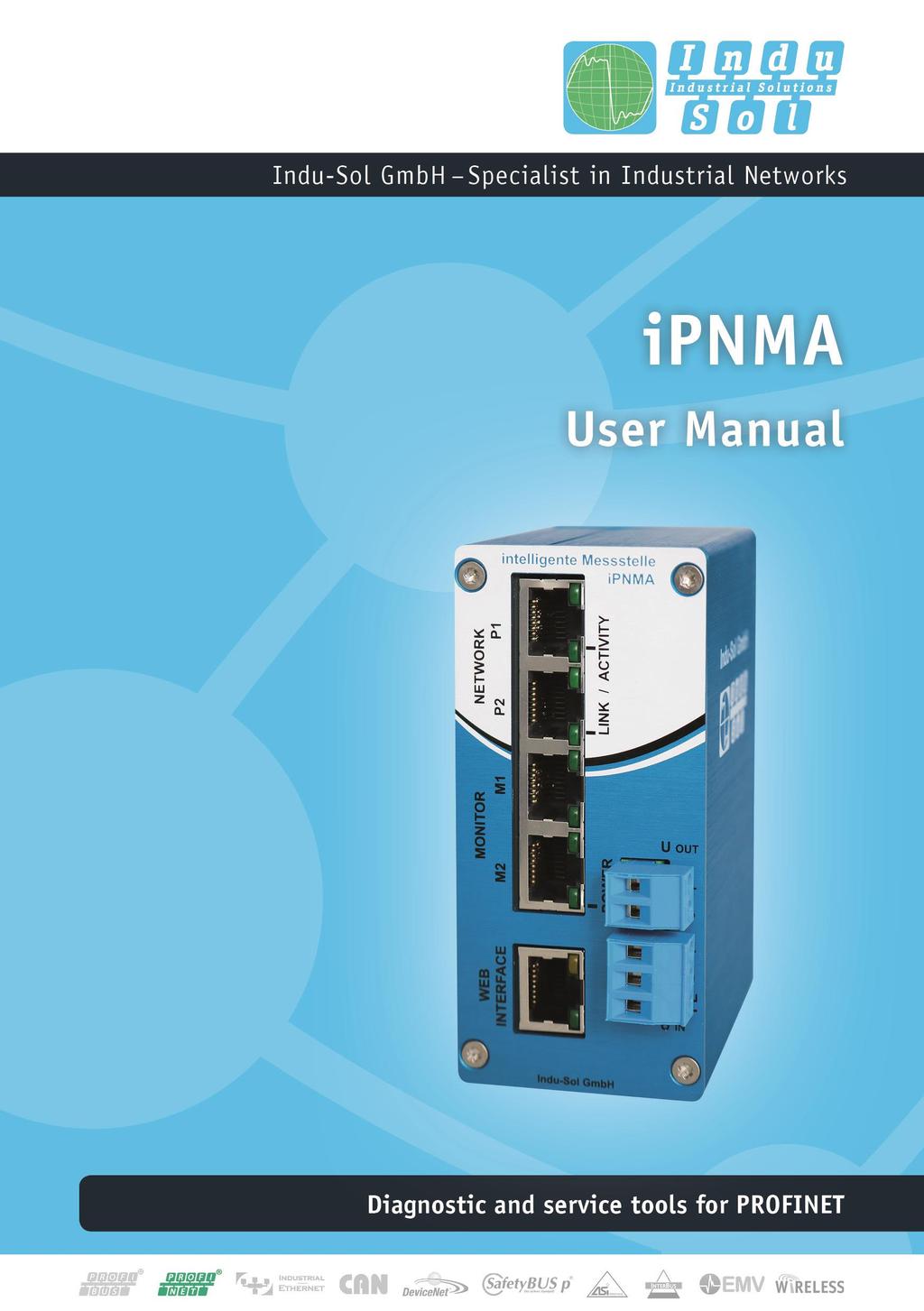
3 Revision overview Revision overview Date Revision Change(s) 29/07/ First version Copyright 2016 Indu-Sol GmbH We reserve the right to amend this document without notice. We continuously work on further developing our products. We reserve the right to make changes to the scope of supply in terms of form, features and technology. No claims can be derived from the specifications, illustrations or descriptions in this documentation. Any kind of reproduction, subsequent editing or translation of this document, as well as excerpts from it, requires the written consent of Indu-Sol GmbH. All rights under copyright law are expressly reserved for Indu-Sol GmbH. Caution! This device may only be put into operation and operated by qualified personnel. Qualified personnel, as referred to in the safety-related information of this manual, are persons who are authorised to put into operation, to earth and to label devices, systems and electrical circuits in accordance with the standards of safety engineering. Intelligent PROFINET Measuring Point ipnma User Manual 3
4 Contents Contents Revision overview 3 Contents 4 1 General information Purpose of use Scope of supply Safety information 6 2 Device ports and status indicators Device ports Installation instructions Voltage supply Voltage supply output Connection to the PROFINET network WEB INTERFACE 10 3 Setup and operation Network settings PROmanage NT 12 4 Device parameters Update rate Alarm (high priority / low priority) Bus device failure Bus device restart Jitter Telegram gaps Telegram overtakes Error telegrams Network load 14 5 Web interface Support and contact Firmware update 15 6 Technical data Technical drawing 16 Intelligent PROFINET Measuring Point ipnma User Manual 4
5 General information 1 General information Please read this document thoroughly from start to finish before you begin installing the device and putting it into operation. 1.1 Purpose of use The intelligent PROFINET measurement point (ipnma) combines the functions of a PROFINET measurement point with a simple PROFINET network analysis. The following quality parameters are determined: Telegram jitter Telegram gaps Telegram overtakes Network utilisation Update rate Device diagnostics Device failures and restarts Error telegrams In this case, the evaluation of the recorded data does not take place on the device itself, but instead all data are queried and processed by the PROmanage NT software. We recommend installing the ipnma permanently in the network connection between the automation device (controller) and the first switch, because the major part of the communication typically passes through here. Two network jacks (Network P1 and P2) are available for this purpose. For a more detailed network analysis, two monitor jacks (Monitor M1 and M2) are available for feedback-free connection of an analysis tool (e.g. PN-INspektor NT or laptop). No adjustments to the PLC program are required for using the ipnma. It works in an entirely manufacturerindependent way; i.e. the analysis works completely independently of the type of control system and bus nodes. Intelligent PROFINET Measuring Point ipnma User Manual 5
6 General information 1.2 Scope of supply The scope of supply comprises the following individual parts: ipnma 3-pole plug-in terminal block (power supply) 2-pole plug-in terminal block (Out for measuring device) CD with PROmanage NT software and device manual Please check the contents are complete before putting into operation. 1.3 Safety information Never open the housing of the ipnma. Opening the housing immediately voids any warranty. If you think the device is defective, send it back to the supplier. Intelligent PROFINET Measuring Point ipnma User Manual 6

7 Device ports and status indicators 2 Device ports and status indicators 2.1 Device ports Monitor X2/M1 IN X2/M2 OUT RJ45 monitor ports X3 - Web interface RJ45 network port Network X1/P1 IN X1/P2 OUT RJ45 PROFINET ports X5 Power supply output X4 Power supply input 24V DC 24V DC + PE Figure 1: Device ports Intelligent PROFINET Measuring Point ipnma User Manual 7

8 Device ports and status indicators Installation 2.2 Installation instructions The ipnma is installed horizontally inside the cabinet on a 35 mm top-hat rail in accordance with DIN EN Figure 2: Device installation on top-hat rail Caution: The following distances must be maintained from other modules for correct installation: From left and right: 20 mm From top and bottom: 50 mm The removal of the ipnma is displayed in Fig. 3. Figure 3: Removal Intelligent PROFINET Measuring Point ipnma User Manual 8
9 Device ports and status indicators 2.3 Voltage supply Operation requires 24 V of external direct current, which is to be connected to the device via the 3-pole plug-in terminal block supplied in the package. The PE contact should be connected to the local PE system. X4 OUT 24V OUT 0V PE DC 24V 0V Ground PE Caution: When connecting, make sure that the polarity is correct. 2.4 Voltage supply output The connection X5 voltage supply Out can be used to provide the voltage supply for PROFINET-INspektor NT or for another measuring device. X5 24V 0V DC 24V Out 0V Ground Out 2.5 Connection to the PROFINET network The ipnma is firmly integrated into the network between the PLC (controller) and the first I/O device or switch for continuous, permanent network analysis. To do this, the device is integrated into the system via the P1 and P2 sockets. Figure 4: Installation ipnma Intelligent PROFINET Measuring Point ipnma User Manual 9
10 Device ports and status indicators 2.6 WEB INTERFACE The LAN connection X3 provides the Ethernet network connection to the ipnma. This involves a 1000BASE-T RJ45 interface. A standard Ethernet cable is used as a connection cable to a PC or laptop (not included in the scope of supply). Both the evaluation of internally recorded data and the parametrisation of the device are possible through this access point. The ipnma is supplied with the following factory-set network configuration: IP address: Subnet mask: A Web-server function is integrated for access to the device and can be opened with an appropriate standard browser (e.g. Microsoft Internet Explorer from version 10 or Mozilla Firefox from version 11; JavaScript must be activated). You can reach the device's user interface by entering the IP address of the ipnma in the browser's command line. Intelligent PROFINET Measuring Point ipnma User Manual 10
, use the Indu-Sol ServiceTool software (software is included in the scope of supply or can be")

11 Setup and operation 3 Setup and operation 3.1 Network settings To set the network addressing (IP address, subnet mask, gateway and host name), use the Indu-Sol ServiceTool software (software is included in the scope of supply or can be downloaded at Open the ServiceTool, make sure that the checkmark is set at ipnma and start the scan (see figure 5). After the scan, the found devices should be displayed as shown in figure 6. By clicking on the desired device, the properties of the device are displayed on the right side. In this view, you can change the IP address, subnet, gateway and host name and save the settings. If DHCP is activated by a checkmark, the ipnma gets the IP address, subnet and gateway from an automatic DHCP server. Figure 5 Settings of the ServiceTool Figure 6 Setting options of the ipnma The Indu-Sol ServiceTool functions independently of the IP address setting of the PC used. All that is needed is a network connection. Intelligent PROFINET Measuring Point ipnma User Manual 11

. For the automatic scan, select the one by ipnma and start the scan (see figure 8).")
12 Setup and operation 3.2 PROmanage NT Generally the PROmanage NT software is needed for using the ipnma. This chapter explains the setting up of the ipnma in the PROmanage NT software. For general installation and operation of PROmanage NT, please refer to the PROmanage NT manual (manual included in the scope of supply or by download at In the first step, you need to start PROmanage NT and log in as Admin. Create a new device in the Analysis and network overview tab by right-clicking (see figure 7). For the automatic scan, select the one by ipnma and start the scan (see figure 8). Finally, checkmark all found ipnmas that should be set up, make the desired settings and then click on Setup (activate the Adopt immediately option). Figure 7: PROmanage NT, create device Figure 8: PROmanage NT, scanning and setting up ipnma Intelligent PROFINET Measuring Point ipnma User Manual 12
13 Device parameters 4 Device parameters 4.1 Update rate The update rate is a fixed value (specific to each device) set in the controller (e.g. 1 ms) indicating the time between data updates in the controller and the I/O device. The decisive criterion for the actual update rate is the network utilisation on the one hand, and the line depth, i.e. the installed network structure and the number of passing devices. The increasing number of passing devices causes fluctuations in the transit time of telegrams, which are called jitter (see Point 5.5 Jitter). By measuring the update rates, it has to be shown that telegram jitter does not exceed half the update rate upwards or downwards (max. 50 % jitter). 4.2 Alarm (high priority / low priority) Diagnostics messages that appear are sent to the PLC as high-priority or low-priority alarms in PROFINET. The event-based division of these alerts (e.g. the shorting of an ET200S module) is defined by each manufacturer themselves for their devices. Unfortunately, a more precise definition is therefore not possible, since the alarms are classified system and node-specifically. 4.3 Bus device failure In PROFINET node failures are diagnosed by means of the watchdog time of the controller or the node itself. This is determined by the set update time between the controller and node, as well as the number of accepted update cycles with missing I/O data. 4.4 Bus device restart The parameter 'Bus device restart' counts all device restarts that occur. A restart of a bus device occurs after a failure or a system start when a bus device has its parameters set by the control system without any faults and then begins the cyclical data exchange. 4.5 Jitter PROFINET communication is based on maintaining the set update rate of each device with the controller. Positive and negative deviations from this configured update time are referred to as 'jitter' in PROFINET. Jitter of up to 50 % of the configured update time is in an acceptable range. Jitter values that are greater than 50 % suggest network performance problems, device issues or an unfavourable layout of the network structure. Intelligent PROFINET Measuring Point ipnma User Manual 13
14 Device parameters 4.6 Telegram gaps A telegram gap in PROFINET means the absence of an update time. Telegram gaps are frequently caused by lost telegrams in the network, e.g. by discards or telegram faults or are caused by incorrect firmware versions of devices. In such cases the devices do not pass on a telegram or 'forget' to send off their own telegram. 4.7 Telegram overtakes A telegram overtake may arise in PROFINET if peak loads occur in the switch or I/O device. When circumstances are particularly bad, a new telegram may be sent before an old one in the buffer of the switch. Telegram overtakes indicate excessive utilisation or device malfunctions. 4.8 Error telegrams This entry indicates the number of faulty telegrams detected in the ipnma connection (checksum errors and packet fragments). 4.9 Network load This includes the network load produced by all reports. This is given as a percentage based on the maximum possible load of a cable at 100 Mbit/s. For stable system operation, the network load should not exceed 20 % in new systems. Intelligent PROFINET Measuring Point ipnma User Manual 14


15 Web interface 5 Web interface 5.1 Support and contact Should you wish to contact us for any reason, further information can be accessed from this page. You can find the manual stored in the download area as a quick aid as well as all important device information. Figure 9: Support and contact 5.2 Firmware update You can perform a firmware update for the ipnma using this function, if required. To do this, the new firmware file is selected and uploaded via the 'Search' button. Following successful installation, triggering a restart is required in the device with the 'Restart' button. Figure 10: Firmware update Intelligent PROFINET Measuring Point ipnma User Manual 15
16 Technical data 6 Technical data Voltage supply: +24V DC Tolerance: 10% Max. power consumption: 150 ma Max. power loss: 4 W Output voltage: 24 V DC (max. 1A) Dimensions (W x H x D): 105 x 49 x 92 mm, incl. top-hat rail mounting and connector terminals Assembly: TS35 DIN top-hat rail (EN 50022) Weight: kg Protection class: IP20 Network port: RJ45 Operating temperature: +5 C to +55 C Storage temperature: -20 C to +70 C Relative air humidity: 10 % to 90 %, non-condensing 6.1 Technical drawing Figure 11: Front view Figure 12: Side view Intelligent PROFINET Measuring Point ipnma User Manual 16

17
Date Revision Change(s) First version
 First version") Revision overview Revision overview Date Revision Change(s) 04.06.2015 0 First version Copyright 2015 Indu-Sol GmbH We reserve the right to amend this document without notice. We continuously work on further
Revision overview Revision overview Date Revision Change(s) 04.06.2015 0 First version Copyright 2015 Indu-Sol GmbH We reserve the right to amend this document without notice. We continuously work on further
Date Revision Change(s) First version Firmware Update 1.5
 First version Firmware Update 1.5") Revision overview Revision overview Date Revision Change(s) 04.06.2015 0 First version 30.06.2016 1 Firmware Update 1.5 Copyright 2016 Indu-Sol GmbH We reserve the right to amend this document without
Revision overview Revision overview Date Revision Change(s) 04.06.2015 0 First version 30.06.2016 1 Firmware Update 1.5 Copyright 2016 Indu-Sol GmbH We reserve the right to amend this document without
Date Revision Change(s) 10/10/ First version
 10/10/ First version") Revision overview Revision overview Date Revision Change(s) 10/10/2017 0 First version Copyright 2017 Indu-Sol GmbH We reserve the right to amend this document without notice. We continuously work on further
Revision overview Revision overview Date Revision Change(s) 10/10/2017 0 First version Copyright 2017 Indu-Sol GmbH We reserve the right to amend this document without notice. We continuously work on further
PROFINET / ETHERNET Switch PROmesh P9
 Indu-Sol GmbH Specialist in Industrial Networks PROFINET / ETHERNET Switch PROmesh P9 Intelligent networking of the latest generation Products Diagnosis Monitoring Training Consulting Industrial Ethernet
Indu-Sol GmbH Specialist in fieldbus technologies INBLOX. User Manual. Diagnostic and service tools for PROFIBUS
 Indu-Sol GmbH Specialist in fieldbus technologies INBLOX User Manual Diagnostic and service tools for PROFIBUS List of revisions Date Revision Change(s) 05/10/2011 0 First version Copyright 2011 Indu-Sol
User Manual Gateway component for EtherNet/IP
 User Manual Gateway component for EtherNet/IP PR100066 1/7/2016 Table of Contents KUNBUS GmbH Table of Contents 1 General Information... 3 1.1 Disclaimer... 3 1.2 Notes Regarding this User Manual... 4
Quick Start Guide NETL ink Ethernet Gateways
 Version en as of FW. Quick Start Guide NETL ink Ethernet Gateways www.helmholz.com Content. Introduction. Checking the Network Situation. Preparing the NETL ink. IP Address Settings on the PG/PC Network
Revision overview. Revision overview. Date Revision Change(s) First version. Copyright 2015 Indu-Sol GmbH
 First version. Copyright 2015 Indu-Sol GmbH") Revision overview Revision overview Date Revision Change(s) 16.03.2015 0 First version Copyright 2015 Indu-Sol GmbH We reserve the right to amend this document without notice. We continuously work on further
Revision overview Revision overview Date Revision Change(s) 16.03.2015 0 First version Copyright 2015 Indu-Sol GmbH We reserve the right to amend this document without notice. We continuously work on further
Installation Manual TH LINK PROFINET. Version: EN Copyright 2014 Softing Industrial Automation GmbH
 Installation Manual TH LINK PROFINET Version: EN-201410-1.00 Copyright 2014 Softing Industrial Automation GmbH Disclaimer of liability The information contained in these instructions corresponds to the
User manual Gateway component Sercos
 User manual Gateway component Sercos DO0227R00 6/28/2016 Table of Contents KUNBUS GmbH Table of Contents 1 General Information... 3 1.1 Disclaimer... 3 1.2 Notes Regarding this User Manual... 3 1.3 Validity...
HIMatrix Safety-Related Controller Maintenance Manual
 HIMatrix Safety-Related Controller Maintenance Manual HIMA Paul Hildebrandt GmbH + Co KG Industrial Automation Rev. 1.00 HI 800 455 E All HIMA products mentioned in this manual are protected by the HIMA
Instruction Manual Power Distribution System SVS16-PN-XX
 Instruction Manual Power Distribution System SVS16-PN-XX 2 Contents 1 General...4 1.1 General mounting guidelines...4. 2 Bus-capable power distribution system SVS16-PN-XX...5 2.1. Overview...5 2.2. Schematic
IV-30 Operating Manual for Pulse Distributor Cassette with potential separation
 IV-30 Operating Manual for Pulse Distributor Cassette with potential separation Edition-/Rev.-Date: 09/08/2006 Document-/Rev.-No.: TR - EAK - BA - GB - 0093-02 Software version: - File name: TR-EAK-BA-GB-0093-02.DOC
SK CU4-PNT-C Part number:
 SK CU4-PNT-C Part number: 275 271 515 PROFINET IO Internal Bus Interface The bus interface may only be installed and commissioned by qualified electricians. An electrician is a person who, because of their
CP ADVANCED. Function
 CP 343-1 ADVANCED Function The CP 343-1 Advanced independently handles data traffic over Industrial Ethernet. The module has its own processor and can be put into service directly using the unique preset
Operating instructions IO-Link master CabinetLine AL19xx
 Operating instructions IO-Link master CabinetLine AL19xx 80273036/00 02/2018 1 Preliminary note Technical data, approvals, accessories and further information at www.ifm.com. 2 Safety instructions Read
Power Supply System KNX PS640-IP
 Power Supply System KNX PS640-IP with Ethernet Interface Installation and Adjustment Elsner Elektronik GmbH Steuerungs- und Automatisierungstechnik Herdweg 7 D-75391 Gechingen Germany Phone: +49 (0) 70
C.M.I. Control and Monitoring Interface. Quick Guide: Mounting and connection Commissioning. Software Version
 www.ta.co.at C.M.I. Control and Monitoring Interface Software Version 1.30.2 Quick Guide: Mounting and connection Commissioning Manual Version 1.08.1 English Table of contents Manual version 1.08.1 EN
Revision History. Version Date Changes Error in PIN description SPI jack Initial version
 MANUAL ANAGATE SPI ANALYTICA GmbH Vorholzstrasse 36 Tel. +49 721 35043-0 E-mail: info@analytica-gmbh.de D-76137 Karlsruhe Fax: +49 721 35043-20 WWW: http://www.analytica-gmbh.de 1 2004-2006, Analytica
Operating instructions. Standstill monitor A / / 2011
 Operating instructions Standstill monitor A300 UK 1 2 3 4 5 6 7 8 7390337 / 01 02 / 2011 1 2 3 4 5 6 7 8 switchpoint min max pulse/min power Made in Germany ifm electronic gmbh D 45127 Essen func. I II
RMx621. Appendix to the operating manual
 Appendix to the operating manual RMx621 DP-slave module ( PROFIBUS-coupler ) from V2.01.00 Connecting the RMx621 to PROFIBUS DP via the RS485 serial interface using the external module (HMS AnyBus Communicator
CRAGG RAILCHARGER Instruction Manual for 10DTC-12V 20DTC-12V 30DTC-24V 40DTC-12V 60DTC-12V
 CRAGG RAILCHARGER for 10DTC-12V 20DTC-12V 30DTC-24V 40DTC-12V 60DTC-12V Contents 1 Warnings, Cautions, and Notes... 1 2 Description... 2 3 Features... 2 3.1 STANDARD FEATURES... 2 3.2 CHARGER REGULATION...
FL MC 2000T. Fiber optic converter for 10/100Base-Tx to single- or multi-mode fiberglass with SC-duplex and ST connections. Data sheet 3379_en_B
 Fiber optic converter for 10/100Base-Tx to single- or multi-mode fiberglass with SC-duplex and ST connections Data sheet 3379_en_B 1 Description PHOENIX CONTACT 2015-07-14 2 Features Media converters provide
RMx621 /FML621. Appendix to the operating manual
 Appendix to the operating manual RMx621 /FML621 DP-slave module ( PROFIBUS-coupler ) from V2.01.00 Connecting the RMx621 /FML621 to PROFIBUS DP via the RS485 serial interface using the external module
multisys User manual Technical parameters D2-MSMT-1 Gateway from Modbus TCP to Modbus RTU, serial RS _EDEBDA _EN
 User manual Technical parameters multisys D2-MSMT-1 Gateway from Modbus TCP to Modbus RTU, serial RS485 System I English Your partner for network analysis KBR Kompensationsanlagenbau GmbH does not accept
Operating instructions AS-i SmartLine module AC3200 AC /00 06/2016
 Operating instructions AS-i SmartLine module AC3200 AC3201 80237876/00 06/2016 Contents 1 Preliminary note...3 1.1 Symbols used...3 1.2 Warnings used...3 2 Safety instructions...3 2.1 General...3 2.2 Target
Quick Start Guide WALL IE. Version. 7 en. as of FW
 Quick Start Guide WALL IE Version en as of FW. www.helmholz.de Contents. Introduction. Connection. Initial access to the web interface. Adapting IP addresses. The bridge mode. Packet filter functionality.
Operating Manual UMB ISO Converter ISOCON Order Number: 8160.UISO
 Order Number: 8160.UISO Status: V3; 17.09.2010c G. Lufft Mess- und Regeltechnik GmbH, Fellbach, Germany 1 TABLE OF CONTENTS PLEASE READ BEFORE USE... 3 DESCRIPTION... 5 UMB ISO CONVERTER ISOCON... 6 CONFIGURATION...
CAN-Bridge. CAN Communications Module for CAN 2.0 A/B, CAN Layer AA01. Manual. Version 1/ from HW 1 & FW 1.00
 CAN-Bridge CAN Communications Module for CAN 2.0 A/B, CAN Layer 2 700-660-2AA01 Manual Version 1/26.01.2011 from HW 1 & FW 1.00 Manual order number 700-660-2AA01/en Systeme Helmholz GmbH Hannberger Weg
Quick Start Guide PN/CAN Gateway Layer 2. Version. 2 en. ab FW
 Version 2 en ab FW 1.02 Quick Start Guide PN/CAN Gateway Layer 2 www.helmholz.de Content 1. Introduction 3 2. Preparation of the PN/CAN Gateway 3 3. Configure PN/CAN Gateway 4 4. PN/CAN Gateway settings
Contents User Manual For PIM
 PIM User Manual 503287 - User Manual For PIM Contents 1. Introduction... 3 2. Navigate this Document... 3 3. Safety Summary... 4 4. Trademarks and Copyrights... 4 5. Contact Information... 5 6. Documentation
SK CU4-EIP-C Part number:
 SK CU4-EIP-C Part number: 275 271 519 EtherNet/IP Internal Bus Interface The bus interface may only be installed and commissioned by qualified electricians. An electrician is a person who, because of their
HARTING scon Introduction and features
 HARTING scon Introduction and features Introduction For the user, HARTING s novel and innovative solutions open up new, more convenient and exten- Switches. The solutions available to date offered only
Quick Startup Guide. datafeed uagate SI. Version: EN Copyright 2016 Softing Industrial Automation GmbH
 Quick Startup Guide datafeed uagate SI Version: EN-052016-1.01 Disclaimer of liability The information contained in these instructions corresponds to the technical status at the time of printing of it
DOCUMENTATION UIMip TECHNICAL AND APPLICATION DESCRIPTION. Last modification: 8 September 2017
 DOCUMENTATION UIMip TECHNICAL AND APPLICATION DESCRIPTION Author: Peter Hauner Last modification: 8 September 2017 2001-2017 Apricum d.o.o. Mažuranićeva 4, 21312 Podstrana, Hrvatska Details, modifications
FIELDBUS TECHNOLOGY ETHERNET- PROFIBUS- INTERFACE PB-XEPI F1144/ 03 INSTALLATION MANUAL
 FIELDBUS TECHNOLOGY ETHERNET- PROFIBUS- INTERFACE PB-XEPI INSTALLATION MANUAL F1144/ 03 2 Installation PB-XEPI D301144 0509 Content About this "Installation manual"...5 Intended use...5 Explanation of
Documentation. CU20xx, CU22xx. Ethernet Switch. Version: Date:
 Documentation CU20xx, CU22xx Ethernet Switch Version: Date: 2.1 2017-12-18 CU20xx, CU22xx - Product overview 1 CU20xx, CU22xx - Product overview CU2005 [} 8] - 5 RJ-45-Ethernet-Ports CU2008 [} 8] - 8
COMELIT AUDIO PLAYER ART
 COMELIT AUDIO PLAYER ART. 20004500-20004501 - 20004502 1 2 TABLE OF CONTENTS 1 INTRODUCTION... 4 1.1 OVERVIEW OF FUNCTIONS... 4 1.2 FUNCTIONAL PRINCIPLE... 4 2 COMELIT AUDIO PLAYER... 5 2.1 SERVER AND
R70 Ethernet to CAN interface Manual (1.4 EN)
") R70 Ethernet to CAN interface Manual (1.4 EN) General information R70 Ethernet to CAN interface Manual Version 1.4 EN, 04/2009, DOC01816 Copyright 2009 by d&b audiotechnik GmbH; all rights reserved. d&b
R70 Ethernet to CAN interface Manual (1.4 EN) General information R70 Ethernet to CAN interface Manual Version 1.4 EN, 04/2009, DOC01816 Copyright 2009 by d&b audiotechnik GmbH; all rights reserved. d&b
Operating instructions. Switching amplifier DN0210 DN / / 2015
 Operating instructions Switching amplifier DN0210 DN0220 UK 80011079 / 00 01 / 2015 Contents 1 Preliminary note...4 1.1 Symbols used...4 1.2 Warning signs used...4 2 Safety instructions...5 2.1 General...5
Hardened Web-Smart PoE & High Power PoE Ethernet Switch
 Quick Start Guide This quick start guide describes how to install and use the Hardened Web-Smart PoE (Power over Ethernet) and High Power PoE Ethernet Switch. This is the switch of choice for harsh environments
Industrial Serial Device Server
 1. Quick Start Guide This quick start guide describes how to install and use the Industrial Serial Device Server. Capable of operating at temperature extremes of -10 C to +60 C, this is the Serial Device
PHOENIX CONTACT - 10/2009
 Factory Line Switches With Standard Functions AUTOMATIONWORX Data Sheet PHOENIX CONTACT - 10/2009 Description The range of Factory Line switches with standard functions in numerous versions can be used
FG-260. Quick Startup Guide. Gateway between EtherNet/IP and PROFINET with PROFINET Controller functionality. Version: MMA-CA EN
 Quick Startup Guide FG-260 Gateway between EtherNet/IP and PROFINET with PROFINET Controller functionality Version: MMA-CA-010260-EN-072015-1.02 Copyright 2014-2015 Softing Industrial Automation GmbH Disclaimer
Revision History. Version Date Changes Description of bridge mode settings via web interface Initial version
 MANUAL ANAGATE CAN ANALYTICA GmbH Vorholzstrasse 36 Tel. +49 721 35043-0 E-mail: info@analytica-gmbh.de D-76137 Karlsruhe Fax: +49 721 35043-20 WWW: http://www.analytica-gmbh.de 1 2004-2006, Analytica
Manual. Decentralized Drive Control MOVIFIT FDC-SNI Connection to PROFIBUS/DeviceNet with UFF41B Fieldbus Gateway
 Drive Technology \ Drive Automation \ System Integration \ Services Manual Decentralized Drive Control MOVIFIT FDC-SNI Connection to PROFIBUS/DeviceNet with UFF4B Fieldbus Gateway Edition 0/0 950 / EN
Operating and mounting instructions
 General Usage IPAS DALI Gateways bring together the crossfunctional KNX installation bus and the lighting control specific DALI-Bus (IEC 60929). Lights with cost-effective, digital DALI ECGs can therefore
Any device, including routers and hosts, is running an implementation of IP address Host
 INSTRUCTION MANUAL IM471-U v0.1 EMI-10L Introduction EMI-10L converter lets you convert a serial RS485 communications port on a bus Ethernet with TCP / IP. The concepts and terms commonly used in the TCP
SK TU4-IOE-M12-C Part Number
 SK TU4-IOE-M2-C Part Number 275 28 256 IO Extension Only qualified electricians are allowed to install and commission the module described below. An electrician is a person who, because of their technical
IP gateway, MDRC IG/S 1.1, GH Q R0001
 , GH Q631 0067 R0001 The IP gateway IG/S is the interface The IP address of the IG/S can be between EIB / KNX installations and IP fixed or received from a DHCP server. CDC 071 130 F0003 networks. Data
EY-EM : Remote I/O module, ecolink
 EY-EM 510...512: Remote I/O module, ecolink510...512 How energy efficiency is improved Optimum adjustment to applications by means of module technology. Reduction in wiring Features Part of the SAUTER
Quick Start Guide. NP290W Turbo Wireless HomePlug
 Quick Start Guide Turbo Wireless HomePlug Contents Chapter 1 Introduction... 3 1.1 Minimum Requirements... 3 1.2 Typical Turbo Wireless HomePlug Connection... 3 1.3 Package Contents... 3 Chapter 2 Turbo
AS-i Safety Output Module, IP20
 a AS-i Safety Output Module Safe outputs and standard inputs in one module Protection category IP20 Figure Housing Inputs digital Outputs Safety, SIL3, cat.4 Input voltage (sensor supply) 1 Output voltage
Arndt & Voß GmbH Elektronik - Meßtechnik
 Axial Elasticity Measuring Unit Contents: Page 1. Functions 2 1.1 Measuring task 2 1.2 Display of measuring results 2 2. Construction 2 3. Connection elements 3-6 4. Programming 7 F5 AUTO/SETUP 7-8 Selection
RTU560 Connections and Settings DIN Rail RTU 560CIG10
 Connections and Settings DIN Rail RTU 560CIG10 Application, characteristics and technical data have to be taken from the hardware data sheet: 560CIG10 1KGT 150 719 Operation The 560CIG10 is a DIN rail
Contents 1. Summary
 Guangzhou Video-star Electronics Industrial Co., Ltd K-BUS R KNX IP Router User manual-ver.1 BNIPR-00/00.1 KNX/EIB Intelligent Installation Systems Contents 1. Summary------------------------------------------------------------------------------------------------------------------------------
DEEP SEA ELECTRONICS PLC
 DEEP SEA ELECTRONICS PLC DSE855 USB to Ethernet Convertor Operator Manual Document Number: 057-205 Author: Anthony Manton DSE855 USB to Ethernet Convertor Operator Manual ISSUE 4 DSE855 USB to Ethernet
ABB i-bus KNX IP Router, MDRC IPR/S 3.1.1, 2CDG110175R0011
 Technical Data 2CDC502086D0201 Product description IP Router 3.1.1 is the interface between KNX installations and IP networks. It can be used as a line coupler or area coupler and can utilize the local
Ha-VIS mcon 3000 Next Generation Introduction and features
 Ha-VIS Next Generation Introduction and features Ha-VIS Next Generation es, managed, for mounting onto top-hat mounting rail in control cabinets General Description Features The fully Managed es of the
Serial PROFIBUS Interface
 Installation Manual Serial PROFIBUS Interface Version: EN-062016-2.3 Copyright 2016 Softing Industrial Automation GmbH Disclaimer of liability The information contained in these instructions corresponds
samos PRO Gateways Operating instructions Doc. No. BA Issued: 09/2009 (Rev. A) 2009 Wieland Electric GmbH
 2009 Wieland Electric GmbH") samos PRO Gateways Operating instructions Doc. No. BA000587 Issued: 09/2009 (Rev. A) 2009 Wieland Electric GmbH This document is protected by the law of copyright, whereby all rights established therein
samos PRO Gateways Operating instructions Doc. No. BA000587 Issued: 09/2009 (Rev. A) 2009 Wieland Electric GmbH This document is protected by the law of copyright, whereby all rights established therein
SMM Series 3G and GSM Modems. Quick Start Guide. Document Number: Version: 1.2 (20 October, 2015)
") SMM Series 3G and GSM Modems Quick Start Guide Document Number: 0013-001-000272 () Documentation Control Generation Date: October 20, 2015 Cybertec Pty Limited All rights Reserved. No part of this publication
SMM Series 3G and GSM Modems Quick Start Guide Document Number: 0013-001-000272 () Documentation Control Generation Date: October 20, 2015 Cybertec Pty Limited All rights Reserved. No part of this publication
Managed 100 Mbps Ethernet Switches TOP FRONT. Click 340/341/342
 Managed 100 Mbps Ethernet Switches Click 340/341/342 The Click 340/341/342 are compact managed Ethernet switches that add network configuration capability, remote monitoring and diagnostics, and integral
Features: DSB98 v1.0 DIN rail mounted switch 9-port DSB98 with buffer power supply for 8 IP cameras
 DSB98 v1.0 DIN rail mounted switch 9-port DSB98 with buffer power supply for 8 IP cameras Edition: 4 from 15.11.2017 Supercedes the edition: 3 from 30.03.2017 EN** Features: Uninterruptible power supply
Features: DSFB108 v1.1 DIN rail mounted switch 10-ports DSFB108 with buffer power supply for 8 IP cameras
 DSFB108 v1.1 DIN rail mounted switch 10-ports DSFB108 with buffer power supply for 8 IP cameras Edition: 3 from 07.03.2018 Supercedes the edition: 2 from 15.11.2017 EN** Features: Uninterruptible power
epowerswitch-8 Power Management Master Slave User's Guide
 epowerswitch-8 Power Management Master Slave User's Guide epowerswitch-8 epowerswitch-8 is a couple of power control units made of a Master named epowerswitch-m8 and a slave named epowerswitch-s8. epowerswitch-m8
MODBUS TCP MODULE INSTRUCTIONS. for use with WSIQ2/WSE
 INSTRUCTIONS MODBUS TCP MODULE for use with WSIQ2/WSE WorldWide Electric Corporation Phone: 1-800-808-2131 Fax: 1-800-711-1616 www.worldwideelectric.net Product Compatibility This communications module
Installation instructions Diagnostic electronics for vibration sensors VSE / / 2007
 Installation instructions Diagnostic electronics for vibration sensors UK VSE00 70406 / 00 07 / 2007 Contents Safety instructions 3 Function and features 4 Mounting 4 Mounting of the sensors 5 Electrical
FL MC 2000E (SM40) LC
 LC") IEC 61850 fiber optic converter with LC fiber optic connection (1310 nm) to convert 100Base-Tx to single- or multi-mode fiber glass Data sheet 3205_en_C 1 Description PHOENIX CONTACT 2014-04-04 2 Features
IEC 61850 fiber optic converter with LC fiber optic connection (1310 nm) to convert 100Base-Tx to single- or multi-mode fiber glass Data sheet 3205_en_C 1 Description PHOENIX CONTACT 2014-04-04 2 Features
Operating instructions. Speed monitor D / / 2014
 Operating instructions Speed monitor D200 80005257 / 00 05 / 2014 Contents 1 Preliminary note...4 1.1 Symbols used...4 1.2 Warning signs used...4 2 Safety instructions...5 2.1 General...5 2.2 Target group...5
CP BACNET Function
 CP 343-1 BACNET Function The CP 343-1 BACnet independently handles data traffic via Industrial Ethernet and BACnet protocol. The module has its own processor and can be put into service directly using
Technical Manual Nova: Cabinet Security Management System (CSMS)
") Technical Manual Nova: Cabinet Security Management System (CSMS) KP_nova_TM_160501_EN 1 Publication May, 2016, Keyprocessor BV Paasheuvelweg 20 1105BJ Amsterdam, The Netherlands www.keyprocessor.com/nova
Technical Manual Nova: Cabinet Security Management System (CSMS) KP_nova_TM_160501_EN 1 Publication May, 2016, Keyprocessor BV Paasheuvelweg 20 1105BJ Amsterdam, The Netherlands www.keyprocessor.com/nova
XPSMF35. Product data sheet Characteristics. Preventa safety PLC compact - Profibus DP protocol. Main. Complementary. Safety module name
 Product data sheet Characteristics XPSMF3542 Preventa safety PLC compact - Profibus DP protocol Main Range of product Product or component type Safety module name Safety module application Nov 13, 2018
Gateway configuration manual IP - KNX EK-BE1-TP
 IP - KNX EK-BE1-TP Index Scope of the document... 3 1 Product description... 3 1.1 Main functions... 4 1.2 Technical data... 4 1.3 Supply... 5 1.4 System requirements for configuration software... 5 1.5
Operating Manual FPGA-based High-Speed Micro-PLC
 ZX20T Operating Manual FPGA-based High-Speed Micro-PLC Zander GmbH & Co. KG Am Gut Wolf 15 52070 Aachen, Deutschland info@zander-aachen.de www.zander-aachen.de Part No.: E61-335-10 Edition: H03 This document
Anybus Wireless Bridge II
 Anybus Wireless Bridge II STARTUP GUIDE SCM-1202-013/SP2167-EN 1.7 ENGLISH Important User Information Liability Every care has been taken in the preparation of this document. Please inform HMS Industrial
SK TU4-PBR Part number:
 SK TU4-PBR Part number: 275 281 100 PROFIBUS DP External Bus Interface The bus interface may only be installed and commissioned by qualified electricians. An electrician is a person who, because of their
DOCUMENTATION UIMip. Authors: Manouchehr Ghahramanian Golzar, Peter Hauner. Last Modification:
 DOCUMENTATION UIMip TECHNICAL AND APPLICATION DESCRIPTION Authors: Manouchehr Ghahramanian Golzar, Peter Hauner Last Modification: 2017-03-02 2001-2017 Apricum d.o.o. Mažuranićeva 4, 21312 Podstrana, Hrvatska
Connections, displays and operating elements C D
 GB /IP- REG-K Operating instructions Art. no. MTN680329 For your safety ¼ DANGER Risk of fatal injury from electrical current. All work carried out on the device may only be performed by skilled electricians.
ROCKETLINX ES8508 ES8508 ES8508F ES8508-XT ES8508F-XT QUICK INSTALLATION GUIDE
 ROCKETLINX ES8508 ES8508 ES8508F ES8508-XT ES8508F-XT QUICK INSTALLATION GUIDE 2000577 Rev B Release Date - September, 2013 INTRODUCTION The RocketLinx ES8508 series features advanced Layer 2 management
Instruction Manual Power Distribution System SVS16-EN-XX
 Instruction Manual Power Distribution System SVS16-EN-XX 2 Contents 1 General...4 1.1 General mounting guidelines...4. 2 Bus-capable power distribution system SVS16-EN-XX...5 2.1. Overview...5 2.2. Schematic
PRODUCT MANUAL. ABB i-bus KNX SV/S KNX-Power Supplies
 PRODUCT MANUAL ABB i-bus KNX SV/S KNX-Power Supplies Contents Contents side 1 General... 3 1.1 Using the product manual...3 1.1.1 Structure of the product manual...4 1.1.2 Notes...4 1.2 Product and functional
Fieldgate SFG500. Technical Information. Intelligent Ethernet/PROFIBUS gateway
 Technical Information Fieldgate Intelligent Ethernet/PROFIBUS gateway Application Fieldgate is a system component that provides an independent access route to a PROFIBUS network. It may be used in a variety
4.7 Digital Input/Output Module 07 DC digital inputs, 8 digital outputs, 8 configurable inputs/outputs, 24 V DC, CS31 system bus
 4.7 Digital Input/Output Module 16 digital inputs, 8 digital outputs, 8 configurable inputs/outputs, 4 V DC, CS31 system bus 1 3 Advant Controller 31 I/O Unit ERR Test 4 1 Fig. 4.7-1: Digital input/output
16-Channel Digital Output Module 120Vac/dc
 Triguard SC300E MDO16FNS 16-Channel Digital Output Module 120Vac/dc (MDO16FNS) Issue 4 October 2005 INTRODUCTION PURPOSE The 120Vac/dc Digital Output Module MDO16FNS provides the output control interface
Installation of the PCMeasure Movement Sensor (30114)
") 1. Hardware: Installation of the PCMeasure Movement Sensor (30114) Connect the sensor to a serial or parallel port of the PC using one of the PCMeasure adaptors, or directly to the PCMeasure Ethernet Box.
1. Hardware: Installation of the PCMeasure Movement Sensor (30114) Connect the sensor to a serial or parallel port of the PC using one of the PCMeasure adaptors, or directly to the PCMeasure Ethernet Box.
SK CU4-PBR-C Part number:
 SK CU4-PBR-C Part number: 275 271 500 PROFIBUS DP Internal Bus Interface The bus interface may only be installed and commissioned by qualified electricians. An electrician is a person who, because of their
HARTING econ 3000 Introduction and features
 Introduction and features HARTING econ 3000 es, unmanaged, for installation in control cabinets General Description Features The Fast es of the product family HARTING econ 3000 are suitable for industrial
BLUE LOG XM / XC. Quick Start Guide. Version
 BLUE LOG XM / XC Quick Start Guide Version 20180827 1 DEVICE OVERVIEW (1) LED: Power supply status (2) LED: Device status (3) LED: Online status (4) USB port (5) Directional pad (6) OK button (7) ESC button
Linienkoppler S KNX. Line coupler S KNX. Line coupler S KNX Status: March 16 (Subject to change) Page 1 of 29
 Page 1 of 29") Linienkoppler S KNX Line coupler S KNX Line coupler S KNX 9070880 Status: March 16 (Subject to change) Page 1 of 29 KNX Contents Contents Page 1 General... 3 1.1 Using the product manual... 3 1.1.1 Structure
Linienkoppler S KNX Line coupler S KNX Line coupler S KNX 9070880 Status: March 16 (Subject to change) Page 1 of 29 KNX Contents Contents Page 1 General... 3 1.1 Using the product manual... 3 1.1.1 Structure
Operating Instructions Differential Pressure Transducer PS27
 Operating Instructions Differential Pressure Transducer PS27 halstrup-walcher GmbH Stegener Straße 10 79199 Kirchzarten/Germany Phone: +49 (0) 76 61/39 63 0 Fax: +49 (0) 76 61/39 63 99 E-mail: info@halstrup-walcher.com
Mounting and Operating Instructions (Simple Programming) Art.No..: , published: 10/2003
 Art.No..: , published: 10/2003") Mounting and Operating Instructions (Simple Programming) Art.No..: 732.29.125, published: 10/2003 Wall Terminal 2000 V.7 Art. No. Model Trans. Format Art. No. Model Trans. Format 917.01.101 Int., 1 Relay
Mounting and Operating Instructions (Simple Programming) Art.No..: 732.29.125, published: 10/2003 Wall Terminal 2000 V.7 Art. No. Model Trans. Format Art. No. Model Trans. Format 917.01.101 Int., 1 Relay
QUINT-BUFFER/24DC/24DC/40
 Buffer module Data sheet 105496_en_01 PHOENIX CONTACT 2013-11-01 1 Description The QUINT BUFFER buffer module combines the electronic switchover unit and power storage in the same housing. The buffer module
MINI-PS AC/10-15DC/8
 Primary-Switched Power Supply, Narrow Design Data Sheet 08/2004 MINI POWER provides: An extra narrow design, with widths of 22.5 mm, 45 mm, and 67.5 mm (0.886, 1.772, and 2.657 in.) Global use due to a
connecdim Gateway G1 Ethernet TCP/IP to DALI
 Gateway G1 Ethernet TCP/IP to LI Independent lighting control for up to 256 LI gears on 4 LI lines Can be expanded by connecting multiple gateways on the same network Cloud based web interface for configuration
Product Information Mixed. Configuration ET 200SP / ET 200AL SIMATIC. ET 200SP Product Information Mixed Configuration ET 200SP / ET 200AL.
 Product Information Mixed Configuration ET 200SP / ET 200AL SIMATIC ET 200SP Product Information Mixed Configuration ET 200SP / ET 200AL Product Information Preface Application planning 1 Mounting 2 Connection
to 12a Added Standard and Electrical requirements for UL table 1.1
 Document changes and version status C-DIAS SAFETY DIGITAL INPUT MODULE CSDI 162 Change date Affected page(s) Changes/expansions/corrections Version 19.12.2013 12 to 12a Added Standard and Electrical requirements
Technical Information Fieldgate SFG500
 TI00029S/04/EN/10.16 71324508 Products Solutions Services Technical Information Fieldgate SFG500 Smart Ethernet/PROFIBUS gateway Parallel access to PROFIBUS networks Monitoring of PROFIBUS and HART device
VDI Pro Voltage & Dry Contact Interface Installation and programming Guide MODEL VDI MK2
 VDI Pro Voltage & Dry Contact Interface Installation and programming Guide MODEL VDI MK2 1 of 18 PREFACE Important Installation Information It is the purchasers responsibility to determine the suitability
User Manual. MS657140X Industrial Fast Ethernet Switch 8x 10/100Base-TX
 User Manual MS657140X Industrial Fast Ethernet Switch 8x 10/100Base-TX CE MARKING This equipment complies with the requirements relating to electromagnetic compatibility, EN 55022 class A for ITE, the