Custom ASCII Protocol
|
|
|
- Oswin Ford
- 6 years ago
- Views:
Transcription


 434-6131 Fax:")
1 Custom ASCII Protocol SERIAL COMMUNICATIONS MANUAL For Laureate Series 2 Digital Panel Meters, Counters, Timers & L-Series Transmitters Now with Ethernet LAUREL Electronics Inc G Airway Ave, Costa Mesa, CA, 92626, USA Tel: (714) Fax: (714) Website: 1
2 1. TABLE OF CONTENTS 1. TABLE OF CONTENTS INTRODUCTION, CUSTOM ASCII SERIAL PROTOCOL SERIAL CONNECTION EXAMPLES JUMPER SETTINGS & FIELD WIRING FOR SERIAL COMMUNICATIONS PROGRAMMING YOUR SERIAL DEVICE FRONT PANEL SETUP, SERIAL COMMUNICATIONS CUSTOM ASCII COMMUNICATION PROTOCOL CONTINOUS MODE COMMAND MODE APPENDIX A: DPM MEMORY ADDRESSES AND DATA DEFINITIONS APPENDIX B: COUNTER / TIMER MEMORY ADDRESSES AND DATA DEFINITIONS APPENDIX C: WEIGHT METER MEMORY ADDRESSES AND DATA DEFINITIONS RECOMMENDED CONVERTER SUPPLIER WARRANTY
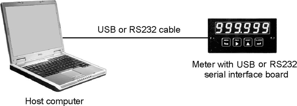
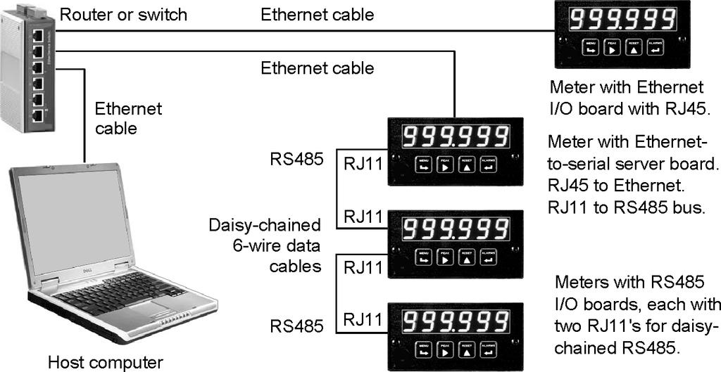
3 2. INTRODUCTION, CUSTOM ASCII SERIAL PROTOCOL The Custom ASCII Protocol is a simple serial communications protocol which is optimized for use with our programmable digital panel meters, counters, timers and transmitters. Digital panel meters, counters and timers accept an optional serial communications plug-in board, which can be any of the following: RS232 board RS485 board with dual RJ11 jacks. RS485 board with dual RJ45 jacks USB board USB-to-RS485 converter board Ethernet board Ethernet-to-RS485 converter board Our two RS485 meter boards use the same circuitry and support the same serial protocols. The boards with dual RJ11 jacks can be daisy-chained using readily available, straight-through 6-wire data cables (not 4-wire telephone cables or crossover cables). Dual RJ45 jacks are available for use with Modbus, as recommended in the Modbus Specification. With either board, the two jacks are wired in parallel to allow daisy chaining of meters with no need for a hub. External repeaters can be used to increase the number of addressable meters. Our USB-to-RS485 and Ethernet-to-RS485 converter boards allow the host meter to function as a normal meter, be connected to a host computer or Ethernet local area network (LAN), and also act as the device server for an RS485 network of up to 31 meters. These should be equipped with RS485 board with RJ11 connectors for daisy chaining with 6-wire data cables. Our DIN-rail transmitters come with either an Ethernet or RS232/RS485 I/O port as ordered. This is in addition to a scalable 4-20 ma output and dual relays, which are standard. Our DIN-rail Ethernet-to-RS485 device server provides an RJ45 jack for connection to the Ethernet, an RJ11 jack to support an RS485 network of meters, plus screw terminals to support an RS485 network of DIN-rail transmitters via a set of 3 or 5 parallel wires (half- or full-duplex). The Modbus Protocol, described in a different manual, is a software-selectable alternative to the Custom ASCII Protocol. It is fully compliant with Modbus over Serial Line Specification V1.0 (2002). It is an industry standard which allows devices by different manufacturers to be digitally addressed on the same network. However, it is more complex than the Custom ASCII Protocol and is only recommended when Modbus compatibility is required. In Ethernet networks, the Modbus TCP protocol is seamlessly converted to Modbus RTU or Modbus ASCII by our Ethernet software. Note: Modbus is not supported by our weight meter. 3
4 USB connection of multiple meters to a PC can be via a USB hub or up to 5 hubs in series. Each USB connection is then automatically assigned a virtual com port number, which can be addressed via software. The USB standard specifies the maximum length of a USB cable as 5 meters (16 ft). A better way to connect multiple meters to a PC USB port is to install an isolating USB-to-RS485 converter board in the first meter and to daisy chain multiple meters each with an RS485 board. Use a standard USB cable, Male Type A to Male Type B, to connect the PC to the server USB/RS485 a b c d RS485 b e RS485 b e f f c c a d a d USB 232 RJ11 RJ11 RJ11 RJ11 RJ11 Computer with USB port meter. The RJ11 output of each RS485 meter can then be connected to the next meter via a 6- conductor straight-through data cable. Up to 30 additional meters may be daisy chained and be addressed using the Custom ASCII Protocol. To connect a meter with a USB board to a Windows PC, use a USB cable with Type A and Type B connectors. Upon first connection, your computer may display Found new Hardware and automatically download and install the required USB driver from the Internet. If installation is not automatic, download the driver file (with a name like CDM v WHQL Certified.zip) from Unzip it into its own directory, and point to that directory as the location of the driver. You will need to use Device Manager (accessible from Control Panel) to determine the Com port. Go down the device list and click on Ports (COM & LPT) and USB serial port (com #). Note the com port # for use with communications to your meter, then exit Control Panel. If you later need to change the Com port, right-click on USB serial port (com #), then on Properties, Port settings, and Advanced. Change port to the desired number, click OK, then exit Control Panel. Ethernet connection of meters and transmitters requires device configuration via our Node Manager Software, a Windows-based application that runs on a host computer. Node Manager automatically discovers all Nodes on a LAN or WAN, plus any devices connected to each Server Node via an RS485 bus. It is used to configure each Node, such as setting communication parameters, naming the Node and associated devices, entering addresses for alarm notification and data requests, selecting the Node's time zone for time-stamping of s and streaming data, and upgrading firmware. Once configuration data has been stored in flash memory of all Nodes, Node Manager Software can be closed. Please see our separate Ethernet Manual. 4

5 3. SERIAL CONNECTION EXAMPLES 5


6 With an Ethernet connection, our Nodes and the host PC can be connected directly to the same LAN, and our software will automatically discover all our Nodes in the LAN. A Node cannot be connected directly to a PC via an Ethernet cable. For connection via the Internet, the PC can be plugged into a local LAN, and the instruments can be plugged into a remote LAN. Laureate Ethernet Nodes and any Devices attached to them via an RS485 bus are automatically discovered by our Ethernet software when the IP address of the remote router is supplied. 6
 from 85-264 Vac or 95-300 Vdc with standard high voltage power, or 12-34V ac or 10-48 Vdc with")

 f - Remote display (or slave) operation. g - Normal operation (other than remote display).")
7 4. JUMPER SETTINGS & FIELD WIRING 1. SAFETY WARNINGS Digital panel meters, counters, timers and transmitters may be powered with AC (mains) from Vac or Vdc with standard high voltage power, or 12-34V ac or Vdc with the low voltage power supply option. To avoid the possibility of electrical shock or damaging short circuits, always unplug the device before opening the case. Please refer to the respective device manuals for full safety information and instruction on how to open the case. Signal wiring changes external to the case can be made safely while the units are under power. 2. JUMPERS ON SERIAL METER BOARDS USB Board & Basic Ethernet Board No jumpers needed. RS232 Board e - Externally enabled RTS (otherwise always enabled) f - Remote display (or slave) operation. g - Normal operation (other than remote display). Note: Board is shipped with jumper g installed. RS485-Modbus Board, Full Duplex Operation b & e - Bias jumpers should be installed on 1 board. a & d - Installed on last meter in long cable run. RS485-Modbus Board, Half Duplex Operation a d c b e f RJ45 b & e - bias jumpers installed on 1 board. c & f - installed for half duplex operation. a - installed on last meter in line with long cable runs. Modbus RJ45 Note: Board is shipped with no jumpers installed. RS485 Board, Full Duplex Operation b & d - Installed on last meter in long cable run. RS485 Board, Half Duplex Operation a & c - Installed for half duplex operation. d - Installed on last meter in line with long cable runs. Note: Board is shipped with no jumpers installed. 7


8 Ethernet-to-RS485 Device Converter Board & USB-to-RS485 Device Converter Board Full Duplex Operation No jumpers for short cable runs. Add b & d for long cable runs. Half Duplex Operation a & c - Installed for half duplex operation. d - Installed on last meter in line with long cable runs. 3. CONNECTOR WIRING, SERIAL BOARD TO COMPUTER 8
9 4. TRANSMITTER CONNECTOR WIRING See below for different signal types Analog out - 1 Analog out + 2 AL2 1 AL2 2 AL1 3 AL1 4 P6 Signal input & excitation output P4 Analog output P3 Solid state relays Signal conditioner board P2 Serial data I/O P1 Power input RS485 RS232 6 N/C TX 5 ARX RX 4 ATX NC 3 GND GND 2 BRX GND 1 BTX N/C 3 Power GND 2 AC neutral or -DC 1 AC high or +DC RS232 cable with rear view of DB9 connector to PC a b E4 d c b a E6 * The termination resistor jumper settings should only be selected if the transmitter is the last device on an RS485 line longer than 200 feet (60 m). E1 E2 E3 a b d c c b a ** Or jumper external BTX to BRX and ATX to ARX (same effect as internal jumpers). Serial Signal Duplex Jumpers Termination Resistor* RS485 Full None E6 a = Transmit E6 c = Receive Half E6 b + d** E6 c RS232 Full None None 9
10 Serial Signal Duplex Jumpers Termination Resistor* RS485 Full None E6 a = Transmit E6 c = Receive Half E6 b + d** E6 c RS232 Full None None * The termination resistor jumper settings should only be selected if the transmitter is the last device on an RS485 line longer than 200 feet (60 m). ** Or jumper external BTX to BRX and ATX to ARX (same effect as internal jumpers). To reset communications to 9600 baud, command mode, Custom ASCII protocol, and Address 1, place a jumper at E1 and power up the transmitter. Analog Output Jumpers Excitation Output* Jumpers Current Voltage E2 a + d E2 b + c 5V, 100 ma E3 a + c; E4 a 10V, 120 ma E3 a + c; E4 b 24V, 50 ma E3 b, E4 none * Attempting to draw more than the rated current will shut down the output. 5. PROGRAMMING YOUR SERIAL DEVICE OVERVIEW Our digital panel meters, counters, timers and transmitters are easily programmed via their serial port using Windows-based Instrument Setup (IS) software, which provides a graphical user interface and is available at no charge. This software allows uploading, editing, downloading and saving of setup data, execution of commands under computer control, listing, plotting and graphing of data, and computer prompted calibration. Digital panel meters, counters and timers can also be programmed via their 4-key front panel as explained in their respective manuals. For Ethernet, please see our separate Ethernet Manual. GETTING STARTED WITH INSTRUMENT SETUP SOFTWARE To install IS software, download the file instrument.exe from our website, double-click on the file name to extract three files, double-click on setup.exe, and follow the prompts. To launch IS software from Windows, press Start => Programs => IS2 => IS2. Establish communications by selecting matching settings between the instrument and PC, and click on Establish. 10
11 Factory default communication settings are 9600 baud, Custom ASCII Protocol, no parity, 8 data bits, and 1 stop bit. You will be prompted to select a Com port. Try different selections until one works, or use Windows Control Panel => Device Manager => Ports (COM & LPT) => Advanced to assign an available Com port number to the detected meter. Once communications have been established, click on Main Menu. The best way to learn IS software is to experiment with it. From the Main Menu, click on Get Setup to retrieve (or get) the existing setup data from your device. Click on View = > Setup to bring up screens which allow you to edit the setup file using pull-down menus and other selection tools. You can save your file to disk by clicking on File = > Save Setup. You can download (or put) your edited file into the device by clicking on Put Setup. Programmable items will only be displayed if the appropriate hardware has been detected, such as the dual relay option for meters. Pressing the F1 key at any time will bring up detailed help information. An analog output is defined in two steps. The input to the device is first scaled to a digital reading in engineering units, and this reading is then scaled to the analog output. The digital reading is also used for setpoint control and can be transmitted as serial data. ADDITIONAL FEATURES The Commands pull-down menu allows you to execute certain functions by using your computer mouse. The Commands pull-down menu will be grayed out unless a Get Setup has been executed. The Readings pull-down menu provides three formats to display input data on your PC monitor. In all formats, use the Pause and Continue buttons to control the timing of data collection, then press Print for a hardcopy on your PC printer. List presents the latest digital readings in a 20-row by 10-column table. Plot generates a plot of digital readings vs. time in seconds, like an oscilloscope. Graph generates a histogram, where the horizontal axis is the reading and the vertical axis is the number of readings. 11
12 6. FRONT PANEL SETUP, SERIAL COMMUNICATIONS 6.1 FRONT PANEL SETUP, DIGITAL PANEL METERS & SCALE METER ONLY Press Menu Select Key.SEr 1. Press until Ser 1 is displayed. Fixed Parameters: - No parity - 8 data bits - 1 stop bit.ser 2. Serial Setup 2 Press Digit Select Key 000 Output filtering 000U Baud rate 000U Output update rate, Continuous Data Output Mode. _0000U Line feed _0000U Alarm data with readings _0000U Control of data output _0000U Meter address Press Value Select Key 0 Send unfiltered signal 1 Send filtered signal baud baud baud baud baud baud baud 60 Hz 50 Hz sec sec sec 0.34 sec sec 0.68 sec sec 1.4 sec sec 2.7 sec sec 5.4 sec sec 10.9 sec sec 21.8 sec sec 43.5 sec sec 86.7 sec 0 No <LF> following <CR> 1 <LF> following <CR> 0 No alarm data with reading 1 Alarm data with reading 0 Continuous data output 1 Data output on ASCII command only Select 1 thru F for addresses 1 thru 15. Select 0. thru F. (with decimal point) for addresses 16 thru
13 Press Menu Select Key.SEr 3. Serial Setup 3 SEr 4. Serial Setup 4 _Addr Modbus Address* Press Digit Select Key 00000U RS485 half or full duplex 00000U Special start & stop char. (entered using Instrument Setup Software) 00000U RTS mode (for RS232) 00000U Termination characters 00000U Data sent, digital panel meter only 00000U Data sent, scale meter only 000U Modbus ASCII gap timeout* 000U Serial protocol 000U Parity Select digit to flash. Press Value Select Key 0 Full duplex 1 Half duplex 0 * Start, <CR> Stop characters 1 Special Start & Stop characters 0 Normal non-latching RTS 1 Single transmission, latching RTS 0 Only at end of all items 1 At end of each item 0 Reading 1 Peak 2 Valley 3 Reading + Peak 4 Reading + Valley 5 Reading + Peak + Valley 0 Net + Gross 1 Net only 2 Gross only 3 Peak only (Net or Gross) 4 Net + Gross + Peak 5 Valley only 0 1 sec 2 5 sec 1 3 sec 3 10 sec 0 Custom ASCII 1 Modbus RTU* 2 Modbus ASCII* 0 None 1 Odd (Modbus only)* 2 Even (Modbus only)* 158 Select 0 through 9 for flashing digit. Address range is 1 to 247. * Modbus is not applicable to our weight meter. 13
14 6.2 FRONT PANEL SETUP, COUNTERS & TIMERS ONLY Press Menu Select Key. Ser 1. Serial Setup 1. Press until Ser 1 is displayed. Fixed Parameters - No parity - 8 data bits - 1 stop bit. Ser 2. Serial Setup 2. Ser 3. Serial Setup 3 Press Digit Select Key 000 Output filtering 000U Baud rate 000U Output update rate, Continuous Data Output Mode. 0000U Line feed 0000U Alarm data with readings 0000U Control of data output 0000U Meter address with Custom ASCII protocol _00000U RS485 half or full duplex _00000U Special start & stop char. (entered using Instrument Setup Software) Press Value Select Key 0 Send unfiltered signal 1 Send filtered signal baud baud baud baud baud baud baud 60 Hz 50 Hz sec sec sec 0.34 sec sec 0.68 sec sec 1.4 sec sec 2.7 sec sec 5.4 sec sec 10.9 sec sec 21.8 sec sec 43.5 sec sec 97 sec 0 No <LF> after <CR> 1 <LF> after <CR> 0 No alarm data 1 Alarm data with reading 0 Continuous data output 1 Data output on ASCII command only Select 1 thru F for addresses 1 thru 15. Select 0. thru F. (with decimal point) for addresses 16 thru Full duplex 1 Half duplex 0 Standard continuous mode 1 Special start & stop characters 14


15 Ser 3. (continued) Press Menu Select Key Ser 4. Serial Setup 4 _ Addr Modbus Address Press Digit Select Key _00000U RTS mode for RS232 _00000U Termination characters _00000U Data sent in continuous mode 000U Modbus ASCII gap timeout 000U Serial protocol 000U Parity Select digit to flash. Press Value Select Key 0 Normal non-latching RTS 1 Single transmission, latching RTS 0 Only at end of all items 1 At end of each item 0 All active items 1 Item #1 only 2 Item #2 only (if active) 3 Item #3 only (if active) 4 Peak only 5 Displayed item 6 Valley only 7 All active items + Peak 0 1 sec 1 3 sec 2 5 sec 3 10 sec 0 Custom ASCII 1 Modbus RTU 2 Modbus ASCII 0 None 1 Odd (Modbus only) 2 Even (Modbus only) 158 Select 0 thru 9 for flashing digit. Address range is 1 to
16 7. CUSTOM ASCII COMMUNICATION PROTOCOL 7.1 SERIAL COMMUNICATION FORMAT The Custom ASCII serial communication format for RS232, RS485 and USB is the following: Duplex... Full duplex for RS232 & RS485. Half duplex selectable for RS485. Baud Rate , 600, 1200, 2400, 4800, 9600, selectable by front panel Menu item Ser 1, Sub-menu item Digit 4 for DPM, "Digit 5" for counter. Parity... None Word length... 8 data bits Stop bit MEASUREMENT DATA FORMAT The basic measurement data format consists of 8 ASCII characters for the DPM, such as <SP> <CR> and 9 characters for the counter, such as <SP> <CR>, where <SP> is the space character and <CR> is the carriage return character. The first character is always a space character or minus sign. A decimal point is always furnished, even when it follows the last digit. Adding a Line Feed Character to the Basic Format Printers and other devices that receive the measurement data may require a line feed character <LF> following the <CR>. The line feed character may be selected in Ser 2. Adding a Coded Data Character to the Basic Format It is possible to add a coded character from A to h to the data string according to the table to the right to indicate the alarm and overload status of the device. If used, this character precedes the <CR>, so it is the last printable character in the string. With the optional <LF> and coded character selected, the data string will consist of 10 characters for the DPM: <SP>999.99A<CR><LF> and 11 characters for the counter: <SP> A<CR><LF>. For example, a coded character G indicates that Alarm 2 only is set and that the DPM is in overload condition. This information is useful when data is supplied to a computer for listing and analysis, or when data is supplied to a Remote Display in a Master-Slave configuration. 16 Alarm # Alarm with No Overload A B C D I J K L Q R S T a b c d Alarm with Overload E F G H M N O P U V W X e f g h
17 The Counter and Scale Meter are capable of supplying more than 1 measurement value (or Item ) with each reading, as selected in Ser 3. In the counter, there can be up to 3 Items plus Peak and Valley values, depending on the selected Function. The scale meter can transmit Net, Gross and Peak weight. Values are transmitted in a continuous string with no space between them. If the 5 th digit in Ser 3 is set to 1, the termination characters of <CR> and optional <LF> appear after each value. If the 5 th digit is et to 0, the termination characters appear only once at the end of the string. In either case, if included, the coded character appears at the end of the last value only. 7.3 NETWORK CONFIGURATIONS The meters and transmitters can operate in a point-to-point mode using RS-232 or RS-485, or in a multi-point mode using RS-485. The point-to-point mode is a direct connection between a computer (or other digital device) and the meter or transmitter. The multi-point mode is a connection from a host computer to a multiplicity of meters or transmitters bused together with their inputs and outputs connected in parallel. For long cable runs, the first and last devices should have a termination resistor installed. It is necessary to set up each device on the bus with a different address from 1 to 31. To command a particular device, its address is used in conjunction with the command, and only that device responds. The outputs of all of the devices on the bus are set to a high impedance state, except the device being addressed. The device addresses range from 1 to 31. A special address to which all meters respond is 0 and should not be used in the multi-point mode. Addressing of meters can be set in Ser 2. A device operating in a point-to-point mode must also be addressed. Although any address will suffice, it is suggested address = 1 be selected as a standard for the point-to-point mode. 7.4 OPERATING MODES The meters and transmitters can operate in a Continuous Mode or a Command Mode. In the Continuous Mode, measurements are continuously transmitted by the meter in a standard data format. Please see the next manual section. In the Command Mode, the meter does not send any data automatically, but responds to commands received from a host computer. Please see the manual section following the Continuous Mode. 17
18 8. CONTINUOUS MODE 8.1 OVERVIEW In the Continuous Operating Mode, measurements are continuously transmitted by the meter or transmitter in a standard data format using printable ASCII characters at a user-selectable rate ranging from 50 or 60 Hz line frequency down to one measurement every 72 seconds. This data may be received by a remote display at a distant location, by a printer for data logging purposes, or by a host computer for data analysis or system control. Both hardware (RTS) and software (XON/XOFF) handshaking are available for RS232, but neither is available for RS METERS OR TRANSMITTERS WITH DPM OR SCALE METER MAIN BOARD The transmission rate of the measurement data can be selected in Ser 1. The meter conversion rate equals the AC power frequency (50 or 60 Hz). Any baud rate may be used, but if less than the minimum baud rate in the table, the transmission rate will decrease accordingly. Output Rate Data Output Rate Minimum Baud Rate Ser 1 Setting 50 Hz / 60 Hz 1 Item Sent 2 Items Sent 3 Items Sent s /.018 s 0.34 s / 0.28 s 0.68 s / 0.57 s 1.4 s / 1.1 s 2.7 s / 2.3 s 5.4 s / 4.5 s 10.9 s / 9.1 s 21.8 s / 18.1 s 43.5 s / 36.3 s 86.7s / 72.3 s / / METERS OR TRANSMITTERS WITH COUNTER / TIMER MAIN BOARD The transmission rate of the measurement data can be selected in Ser 1". Data transmission is initiated at the end of the calculation time following the gate time. Data is completely transmitted for one measurement before the calculation of the next measurement is started. Therefore, the reading rate is influenced by the baud rate, the number of items transmitted, and gate time. If the selected gate time is less than that shown in the table below, it is not the determining factor of the reading rate. If it is greater, then it is the determining factor. Time intervals (reciprocal of rate) between transmissions at the reading rate are: 18
19 Baud Rate Time 1 Item Min Gate Time 2 Items Min Gate Time 3 Items Min Gate Time 4 Items Min Gate s 0.18s 0.09s 0.05s 0.02s 0.01s 0.01s 0.34s 0.15s 0.06s 0.02s 0.01s 0.01s 0.01s 0.70s 0.35s 0.18s 0.09s 0.04s 0.02s 0.01s 0.67s 0.32s 0.15s 0.06s 0.01s 0.01s 0.01s 10.03s 0.52s 0.26s 0.13s 0.07s 0.03s 0.02s 1.00s 0.49s 0.23s 0.10s 0.04s 0.01s 0.01s 1.37s 0.68s 0.34s 0.17s 0.09s 0.04s 0.01s 1.34s 0.65s 0.31s 0.14s 0.06s 0.01s 0.01s The data transmission rate may be reduced by sending data every other reading, every fourth reading, or less. This selection is made in Ser 1. A computer, if busy with other tasks, may be unable to keep up with the faster data rates of the meter, so a handshake function is available that provides the computer with control over the meters data transmissions. 8.3 RTS CONTROL RTS control does not apply to transmitter, where the RTS line is always held high, nor to RS485. DPMs and counter / timers have two RS232 RTS modes: unlatched and latched. These modes are selected in Ser3. In the unlatched mode, the measurement transmission is enabled by a high RTS level and is disabled by a low RTS level. When disabled, any character being sent is completed. When enabled, any characters remaining in the data format are transmitted before the next measurement transmission. The computer, when its receive buffer is nearly full, takes the RTS line low to halt data transmission. When its receive buffer has emptied, it takes the RTS line high to enable more data transmissions. Some measurements could be missed in the process. In the latched mode, the RTS input is polled every 3.3 ms. When a high level is detected, RTS is latched true, even though the RTS line goes low immediately. At the end of each calculation, the latched RTS value is checked. If it is true, a complete measurement transmission (from 1 to 4 values) is made without interruption, regardless of the state of the RTS line during that time. At the end of the complete transmission, the latched RTS value is reset false, even though the RTS line may be high at that instant. The RTS latch does not go true again until the RTS line is first returned to a low level after the completion of the transmission and then is taken high again. Latched control provides print command operation by sending a transmission for each RTS pulse. If a second pulse occurs during the transmission, it is not recognized. 8.3 XON / XOFF CONTROL Applicable to RS232, not RS485. A measurement transmission is enabled by the receipt of an ASCII XON character. It is disabled by the receipt of an ASCII XOFF character. 19
20 9. COMMAND MODE 9.1 OVERVIEW In the Command Mode, the device does not send any data automatically, but responds to commands received from a host computer. These commands can be: To transmit the latest, peak, or valley measurement. To reset the meter completely or just the peak and valley values and latched alarms. To display a value sent from the computer. To transmit present setup parameters. To receive new setup parameters. To monitor or alter data in selected memory locations of the meter. The selection of either the Continuous mode or the Command Mode can be made from the front panel Menu selection Ser 2. The meter will not respond to a command in the Continuous Mode, except the command A1, which puts the meter into the Command Mode. 9.2 COMMAND MODE FORMAT The minimum format is 4 characters. Example: *5A1 After any command that causes a Meter Reset, such as C0, F, W, X, the Counter sends an R character after the Reset is complete and the Counter is ready to accept a new command. CHAR 1 - COMMAND IDENTIFIER All commands begin with * followed by the meter address, then a command letter followed by a sub-command number or letter. Additional characters may be appended. All commands terminate with <CR> (<LF> ignored). The counter may be assigned a different recognition character via the RS232 / 485 serial port, but will still recognize the *. Char # Character Description * 0-V A-Z 0-U Command Identifier (Recognition Character) Device Address (0 addresses all devices, 1-V specific) Command Function Sub-command (or # Bytes or Words of data being transferred) CHAR 2 - ADDRESS CODES The next table is the Serial Communication Address Codes following the * for each meter address number. Also shown is the corresponding character that is set in menu item SER 2. 20
21 Meter # Meter SER 2 Digit 5(6) Serial Comm Address Code Meter # Meter SER 2 Digit 5(6) Serial Comm Address Code A B C D E F A B C D E F A. B. C. D. E. F. G H I J K L M N O P Q R S T U V CHARS 3 & 4 - COMMANDS AND SUBCOMMANDS The examples below use a default address of 1 following the *. Substitute the desired address from the above table of Serial Comm Address Codes. All command sequences shown must terminate with <CR>, followed by an optional <LF>. COMMUNICATIONS MODE Continuous mode *1A0 Command mode *1A1 REQUEST DPM VALUES Get reading** *1B1 Peak reading *1B2 Valley reading *1B3 ** The meter transmits the value or values selected in Ser 3. REQUEST SCALE METER VALUES Get reading** *1B1 Net only *1B2 Gross only *1B3 Peak only *1B4 ** The meter transmits the value or values selected in Ser 3. 21
22 REQUEST COUNTER VALUES All active items 1, 2 or 3 *1B0 Item 1 *1B1 Item 2 *1B2 Item 3 *1B3 Peak *1B4 Displayed item *1B5 Valley *1B6 All active items + Peak + Valley *1B7 RESET FUNCTIONS, DPM & SCALE METER Cold reset *1C0 Reads NVMEM into RAM locations after RAM is zeroed. Latched alarms reset *1C2 Peak value reset *1C3 Remote display reset *1C4 External Input B true *1C5 External Input B false *1C6 External Input A true *1C7 External Input A false *1C8 Valley reset *1C9 Tare function *1CA Tare reset *1CB RESET FUNCTIONS, COUNTER / TIMER Cold reset *1C0 Reads NVMEM into RAM locations after RAM zeroed. Function reset *1C1 Resets all total values and/or peak value. Latched alarms reset *1C2 Peak value reset *1C3 Remote display reset *1C4 Resets Item 3 to zero if not Arith or Batch. Removes Alarm View or Peak View if on. External Input B true *1C5 External Input B false *1C6 External Input A true *1C7 External Input A false *1C8 Valley value reset *1C9 Store totals & reset *1CA 9.3 READING AND WRITING TO RAM AND NONVOLATILE MEMORY CHARACTERS 1, 2 The Recognition character and Meter Address Code are the same as shown in previous table. 22
23 CHARACTER 3: Command character: G Read bytes from RAM Memory F Write bytes to RAM Memory (DPM and Scale meter only) R Read bytes from Upper RAM Memory Q Write bytes to Upper RAM Memory X Read words from Non-Volatile Memory W Write words to Non-Volatile Memory CHARACTER 4: Number of bytes (G, F, R, Q) or words (X, W) Code # 1 = 1 2 = 2 3 = 3 4 = 4 5 = 5 6 = 6 7 = 7 8 = 8 9 = 9 A = 10 B = 11 C = 12 D = 13 E = 14 F = 15 G = 16 H = 17 I = 18 J = 19 K = 20 L = 21 M = 22 N = 23 O = 24 P = 25 Q = 26 R = 27 S = 28 T = 29 U = 30 CHARACTERS 5, 6 See tables for the RAM MEMORY ADDRESSES and NONVOLATILE MEMORY ADDRESSES with their respective data definitions. CHARACTERS 7 & UP: Data to be written (F, Q, W). GENERAL, READING AND WRITING RAM MEMORY DATA RAM memory data is read and written as a continuous string of bytes consisting of 2 hex characters (0-9,A-F) per byte. Included in the command are the total number of bytes to be transferred and the most significant address in RAM of the continuous string of bytes. The format is: Read lower RAM data *1Gnaa Write lower RAM data *1Fnaa<data> Read upper RAM data *1Rnaa Write upper RAM data *1Qnaa<data> where: n is the number of bytes to be read or written. aa is the most significant address in RAM of the bytes to be read or written. <data> is n bytes of 2 hex characters per byte in order from the most to the least significant byte. 23
24 The number of bytes n consists of a single code character representing values from 1 to 30 as shown above under CHARACTER 4. The most significant address aa consists of 2 hex characters as shown below under RAM MEMORY ADDRESSES AND DATA DEFINITIONS. GENERAL, READING AND WRITING NONVOLATILE MEMORY DATA Nonvolatile data is read and written as a continuous string of words consisting of 2 bytes or 4 hex characters (0-9,A-F) per word. Included in the command is the total number of words to be transferred and the most significant address in nonvolatile memory of the continuous string of words. The format is: Read nonvolatile memory data *1Xnaa (Meter reset occurs after all data is read.) Write non-volatile memory data *1Wnaa <data> (Meter reset occurs after data is written.) where: n is the number of words to be read or written. aa is the most significant address in nonvolatile memory of the words to be read or written. <data> is n words of 2 bytes or 4 hex characters per word in order from the most to the least significant address The coded number of words n consists of a single character representing values from 1 to 30 as shown under CHARACTER 4. The most significant address aa consists of 2 hex characters as shown under NONVOLATILE MEMORY ADDRESSES. 9.4 COMMAND MODE FOR REMOTE DISPLAY OPERATION OF DPM OVERVIEW A DPM can serve as a remote display that responds to values sent via serial communications by a PC or by another DPM in a Master-Slave configuration. In one application, the DPM sends readings to a PC, which then processes the readings and transmits values back to the DPM for display. There are 2 modes in which the DPM may act as a remote display: MODE 1: DPM with Signal Conditioner Card and not in Remote Display Mode SETUP (left digit) = 0 4-1/2 digit DPM = 2 4-1/2 digit DPM with Count by 10 = 3 3-1/2 digit DPM The baud rate must be set the same as the source. The PC Controller uses the H command to cause the display to halt its normal readings and display the value sent by Serial Communications instead. The DPM must be in the Command mode to receive the data. The data format sent via Serial Communications is: *#HSDDDDD.A <CR> where the decimal point is in front, behind (as shown), or between the D s (digits). 24
25 A total of 11 characters plus a CR must be included and sent as ASCII characters. Those in quotes below are included as shown. The other symbols represent a range of characters except for CR which is the ASCII character 0D. * = Command identifier # = Device address from 1 to 9, A to V, or 0 for common address H = Command letter S = Sign of value, space (or +) for positive, - for negative value D = Digit from 0 to 9 * = Decimal point placement and must always be included A = Alarm and overload character code, A to H <CR> = Carriage return character The following table lists the Alarm and Overload characters. ALARM CONDITION NO OVERLOAD OVERLOAD Neither Alarm on Alarm 1 only on Alarm 2 only on Alarms 1 & 2 on A B C D E F G H If the DPM is in the Continuous mode, it must be put into the Command mode by sending *#A1 prior to sending the remote display value. The Remote Display value remains on the display until one of the following occurrences: a. The command *#C4 is sent removing the Remote Display value and returning to the normal readings without resetting the DPM. b. The command *#C0 is sent causing a Cold Reset of the DPM. c. The command *#C1 is sent causing a Warm Reset of the DPM. d. Front panel pushbuttons RESET and MENU are simultaneously pushed to cause a Cold Reset of the DPM. Notes: After the Remote Display value is entered, the DPM can be put back in the Continuous mode with the command *#A0 without disturbing the display s value. DPM must be in the Command mode for a., b., or c. above. It may be put into the Command mode while displaying a remote display value with the *1A1 command without affecting the display. If PEAK (manual or external) or ALARM VIEW (manual) is activated while the remote value is being displayed, the peak or alarm value is displayed and cannot be removed except by Remote Display Reset (a., b., or c. above in Command mode) or by manual RESET. If a Remote Display value is sent while in PEAK or ALARM VIEW, it is ignored, but when PEAK or ALARM VIEW is turned off, the Remote Display value comes on. 25
26 MODE 2: DPM with Signal Conditioner Card and in Remote Display Mode SETUP (left digit) = 1 Remote Display mode The baud rate must be set the same as the source which may be a PC Controller or another DPM. The format is the Slave Format. This is the same as MODE 1 above but without the Command Identifier *, the address #, and the Command letter H. This is the same format that data is transmitted from a DPM in the Continuous mode. The string of characters must be exactly 8 characters plus the CR in length. SDDDDD.A <CR> No commands can be received in this mode but the front panel MENU can be accessed. Any transmissions received other than properly formatted data will result in a meaningless display. Alarm setpoints, Peak readings and external control functions are disabled while the Remote Display value is being displayed. When the DPM is Reset, it displays RESET continuously until data is received. DATA FORMAT *1HSDDDDD.A S = Sign, either blank (for +) or - D = Digit from 0 to 9, five digits total. Always include a decimal point even at the end. A = Alarm character as defined in 8.4, Mode COMMAND MODE FOR REMOTE DISPLAY OPERATION OF COUNTER / TIMER The Counter has 13 Display Modes (0-12). Modes 0-5 are normal measurement modes. Modes 6-12 are dedicated to Remote Display without making any normal readings. In any of the 13 modes, remote display data may be received via RS-232 or RS-485 and be displayed. The remote data requirements and the Remote Display capabilities vary for the different display modes and selected Input Functions. The mode is selected by Menu item ConFiG Digit 3 from the following list: Normal Readings While Displaying Remote Data 0 Normal display, Exponent Overflow 1 Normal display, Overflow 2 1 right-hand dummy zero 3 2 right-hand dummy zeros 4 Real time clock, multi-format 5 Real time clock, hh.mm,ss Addressable Commands H, K or L H, K or L H, K or L H, K or L H, K or L H, K or L 26
27 Remote Display Only No Normal Readings 6 Addressable remote display 7 Single value remote display 8 1st value of value sequence 9 2nd value of value sequence A 3rd value of value sequence B C 4th value of value sequence Programmed to select specific data from a data string Addressable Commands H, K or L commands 1 value only 1-4 sequential Values 2-4 sequential Values 3-4 sequential Values 4 sequential Values 1 value only The addressable commands of Modes 0-6 can display remote data on one or more Counters having the command address in a multi-point configuration or a single Counter having the command address in a Point-to-point configuration. Modes 7-11 (B) do not use addressable commands, but values only. They are primarily designed for Host Counter or Scale meter to Slave Counter or remote display applications but may be used also in Host Computer to Remote Display Counter configurations. Since the Host Counter may be selected to transmit up to four sequential measurement values, Item 1, Item 2, Item 3 and Peak, (Scale meter transmits up to 3 values) each measurement cycle, Modes 8-11 provide the ability of the Remote Display to extract one of four sequential values and display it. Modes 0-5 are normal counter modes that may be commanded as follows: 1. H Command. Overrides the normal display reading only. 2. K Command. The value is not displayed, but is stored as Item 3 if Item 3 is not being used. It may then become the source, if selected, for the Alarm comparison and the Analog Output. Item 3 is normally only used for the Batch and Arithmetic functions. 3. L Command. Both 1 and 2. In addition, the H, K, L commands may or may not include a coded Alarm character. If included, this character always overrides the internal Alarm comparisons and determines the alarm indicators, the relay operation and the alarm character sent with the serial communications. Readings continue to be made internally during Remote Display operation and may be received by a Host Computer, manipulated, and returned as remote data. When reset by a *1C4 Command, the display returns to its internal readings, the Alarms to their internal comparisons, the Item 3 value to zero, and the Analog Output as scaled for zero input. A signal conditioner board must be present in these modes to return to normal readings. If no signal conditioner board is present, any Mode setting from 0-5 automatically changes to Mode 6. Modes 6-11 are used for remote display operation only. No normal readings are made. A signal conditioner board is optional, and if present, is ignored. When reset, the display shows reset until the first remote display data is received. Mode 6 is an addressable remote display mode that uses the H, K, L commands. 27
28 Mode 7 is not addressable, and data representing a value to be displayed is received in a pointto-point connection. In addition to being displayed, that value is put into Item 3, where it may be selected for Alarm comparisons and/or for Analog Output. If a Coded Alarm character is included, it overrides the internal alarm comparisons. Modes 8-11 are able to extract one value of data from a sequence of values, and display that particular value only. Using this mode, multiple slave counters connected to a Host Counter could each be displaying a different Item value. Also, the extracted value is put into Item 3 where it may be selected for Alarm comparisons and/or Analog Output. If a Coded Alarm character is included at the end of the sequence, it is ignored. The remote display reading can only be changed by Meter Reset, a *1C4 Remote display reset command, or another remote display H or L command. Mode 12 - Remote display "C" allows extraction of data from an ASCII string that contains multiple data values or non-numeric characters. It can accommodate selected Remote Start and Remote Stop characters. Any number of characters between the Remote Start character and the data can be masked OFF. Up to 8 display characters (including sign and DP) can be masked ON. Any number of characters between the last displayed character and the Remote Stop character can be masked OFF. When CONFIG, CXXX is set, the meter is a Masked Remote Display, and the following parameters determine its operation. These must be set while the meter is set to something other than CONFIG, CXXX, because that is the one setting for which there is no two-way serial communication with the meter. It is suggested to use CONFIG, 6XXX to set the following parameters, and then to use CONFIG, CXXX for operation. 1. Remote Start character (set to 00 if none desired). 2. Remote Stop character (set to 00 if none desired). Note: Only one of the above can be set to Number of characters following the Remote Start character to be ignored. 4. Number of characters following the ignored characters to be displayed. Either Instrument Setup.exe or Serial.exe may be used to set the values for the Remote Display C mode. These programs may be downloaded from our website. COMMAND FORMATS The basic two Command formats of the data sent via Serial Communications are: *#CSDDDDDD.A<CR><LF> where the decimal point is to the right of any one of the D s (digits). *#CSD.DDDEPA<CR><LF> This is the exponential format. The decimal point is fixed. Alarm comparison and Analog Output are not valid in this format. * = Recognition character # = Device address from 1-9, A to V, or 0 for common address. C = Command letter H, K, L. 28
29 S = Sign of value, space (or +) for positive, - for negative value. Sign is optional in display modes 0-7, required in D = Digit from 0 to 9. Number of digits may be 1-6 in display modes 0-7, but must be 6 in P = Power of , A-F where A-F represents A = Optional Alarm Character as defined in section 2.1 <CR> = Carriage return character <LF> = Optional line feed character (ignored) These basic Command formats are used when the Remote Display Counter is in display modes 0-6. The basic Data formats are the same except *#C is omitted. The basic Data formats are used in display mode 7. Single or multiple (2-4) Data formats are used in display modes Example: SDDDDDD.SDDDDDD.SDDDDDD.SDDDDDD.A<CR><LF> <LF> optional, Ser 3 Digit 5 = 0, termination characters only at end of data string or SDDDDDD.<CR><LF>SDDDDDD.<CR><LF>SDDDDDD.<CR><LF>SDDDDDD.A<CR><LF> Ser 3, Digit 5 = 1, termination characters at end of each data item. 9.6 RECOGNITION CHARACTER, AND START AND STOP CHARACTERS The meter recognizes an asterisk ( * ) as the command recognition character. In the counter, another command recognition character may be chosen to make the meter compatible with an existing system. The meter will still respond to an asterisk. For all meters, in continuous mode, a device, such as a printer, may require a start and stop bit to recognize the data string being sent. Normally there is no start bit and the stop bit is a carriage return <CR>. When the Counter is in a normal operating mode (not Remote Display), SER 3, XDXXX can be set for the following combinations: D Command Recognition Character Continuous Transmission Readings * Selected * Selected None None Selected Selected CR CR Selected Selected Either Instrument Setup.exe or Serial.exe may be used to set the Command recognition character and the start stop characters. These programs may be downloaded from our website. 29
30 10. APPENDIX A: DPM MEMORY ADDRESSES AND DATA DEFINITIONS 10.1 DPM 1-BYTE RAM MEMORY DATA (L) = Lower memory, (U) = Upper memory. The bit assignments below constitute an 8-bit binary number, which needs to be converted to Hex using a program such a Scientific Calculator under MS Windows Accessories. To change an Item in DPM RAM Memory, write the converted Hex value to the Hex Address shown in the left column. To change an Item in Nonvolatile Memory, go to table 10.4, read the existing twobyte word (MS byte and LS byte) from the DPM for the Hex Address which includes the Item to be changed, edit the MS or LS byte as appropriate, and write the edited word back to the Hex Address. Be careful not to overwrite the Sig Cond Type LS byte under Hex Address 15. Hex Address Item Name Bit Assignment DE (L) Configuration Bit Linear data 1 Custom curve (Extended DPM) 0 Spare 0 No Auto-Tare 1 Auto-Tare 0 0 Peak button displays Peak 0 1 Peak button displays Valley 1 0 Peak b. displays Peak then Valley 1 1 Peak button tares the meter Not rate Rate x Rate x Rate x Rate x Rate x Rate x 10,000 BF (L) Analog Setup Bit Analog output unfiltered 1 Analog output filtered ma current output V voltage output ma current output V to +10V output 30
31 69 (L) Serial Cnfg3 Bit Send Reading Send Peak Send Valley Send Reading + Peak Send Reading + Valley Send Reading + Peak + Valley 0 <CR> or <CR><LF> at end of all Items 1 <CR> or <CR><LF> at end of each Item (if no Alarm character) 0 Non-latching RTS 1 Latching RTS 0 Normal continuous TX 1 Special Start & Stop characters 0 Full duplex 1 Half duplex 35 (L) Decimal Point 01 Byte values in hex XXXXX. 02 (2 hex characters/byte) XXXX.X 03 XXX.XX 04 XX.XXX 05 X.XXXX 06.XXXXX 34 (L) Lockout2 0 = unlocked 1 = locked 33 (L) Lockout1 0 = unlocked 1 = locked Bit Menu item & front panel lockout 1 Serial configuration 1 Analog output scaling 1 Alarm setpoint programming 1 Alarm setup 1 Front panel DPM reset 1 Front panel Peak & Alarm reset 1 View alarm setpoints 1 View Peak value & Tare function Bit Menu item & front panel lockout 1 Offset, Lo & Hi readings 1 Scale, Lo In, Hi In 1 Filter Setup 1 Setup, Config & Decimal Point 1 InPut Menu Item 31
32 32 (L) Serial Cnfg2 Bit X X X X X Binary Custom ASCII addr Continuous mode 1 Command mode 0 Alarm data not included with rdg. 1 Alarm data included with rdg. 0 No <LF> following <CR> 1 <LF> following <CR> 31 (L) Serial Cnfg1 Bit Continuous Output Data Rate 60 Hz 50 Hz s 0.02s :13 1: :25 2: :50 5: :40 11: :20 23: :41 46: :17:21 1:32: baud baud baud baud baud baud baud 0 Send unfiltered value 1 Send filtered value 32
33 2F (L) Filter Bit Auto Filter Batch (16 samples) filter Time constant 60 Hz 50 Hz Moving average 0.07 s s Moving average Moving average Moving average Moving average Moving average Moving average Moving average Unfiltered 0 Low adaptive threshold 1 High adaptive threshold 0 Display batch 1 Display filtered signal 0 Take peak of unfiltered signal 1 Take peak of filtered signal 0 Alarm from unfiltered signal 1 Alarm from filtered signal 2D (L) Setup Bit EXT IN 1 EXT IN 2 BOTH Mtr Reset Mtr Hold Mtr Reset Fct Reset Rd Pk/Vl Mtr Reset Mtr Hold Rd Pk/Vl Fct Reset Mtr Hold Tare Mtr Reset Rd Pk/Vl Tare Fct Reset Tare Mtr Reset Mtr Reset DP2 DP3 DP DP3 DP4 DP Fct Reset Disp Blank Mtr Reset Mtr Hold Disp Blank Mtr Reset Rd Pk/Vl Disp Blank Fct Reset Tare Disp Blank Mtr Reset Rd Valley Read Peak Fct Reset Tare Tare Reset Mtr Reset 0 0 Scale using Scale & Offset method 0 1 Scale using Coordinates of 2 Points method 1 1 Scale using Reading Coordinates of 2 Points 0 60 Hz power 1 50 Hz power 33
IPM490 / IPM500 SERIAL COMMUNICATIONS MANUAL
 IPM490 / IPM500 SERIAL COMMUNICATIONS MANUAL For Series 2 Digital Meters Custom ASCII protocol 10 Thomas, Irvine, CA 92618, USA Tel: (949) 465-09001 Fax: (949) 465-0905 Website: www.futek.com 1. TABLE
THE LAUREATE SERIES. Serial Comunications Manual
 THE LAUREATE SERIES Serial Comunications Manual LAUREL Electronics Inc. 3183-G Airway Ave, Costa Mesa, CA USA 92626 Tel: (714) 434-6131 Fax: (714) 434-3766 Website: www.laurels.com CONTENTS 1.0 HARDWARE
LAUREL. Laureate Digital Panel Meter for Process and Ratiometric Signals ELECTRONICS, INC. Features. Description
 LAUREL ELECTRONICS, INC. Laureate Digital Panel Meter for Process and Ratiometric Signals Features Reads process signals from ±200 mv to ±600V or ±2 ma to ±5A full scale Ratiometric mode for bridges and
HI-QPM SERIES. Serial Comunications Manual. OTEK Inc E. Tennesee St, Tucson, AZ USA 85714
 HI-QPM SERIES Serial Comunications Manual OTEK Inc. 4016 E. Tennesee St, Tucson, AZ USA 85714 WARRANTY Otek Inc. warrants its products against defects in materials or workmanship for a period of one year
LAUREL. Laureate RTD Temperature Panel Meter / Controller ELECTRONICS, INC. Features. Description. Specifications
 LAUREL ELECTRONICS, INC. Laureate RTD Temperature Panel Meter / Controller Features Factory calibrated for 100Ω platinum, 10Ω copper & 120Ω nickel RTDs 2, 3 or 4-wire connection with lead resistance compensation
LAUREL. Laureate Pulse or Analog Input Batch Controller Automatic batch control for repetitive liquid fill operations ELECTRONICS, INC.
 Description LAUREL ELECTRONICS, INC. Laureate Pulse or Analog Input Batch Controller Automatic batch control for repetitive liquid fill operations Features Available for turbine flow meter pulse signals
TC Type Range Conformity Error. J -210 C to +760 C (-347 F to F) ±0.09 C (±0.16 F) K -244 C to C (-408 F to F) ±0.1 C (±0.
 ±0.09 C (±0.16 F) K -244 C to C (-408 F to F) ±0.1 C (±0.") LAUREL ELECTRONICS, INC. Laureate Thermocouple Panel Meter / Controller Features Factory calibrated for thermocouple types J, K, T, E, N, R, S Entire range of each thermocouple in one scale Highly accurate
LAUREL ELECTRONICS, INC. Laureate Thermocouple Panel Meter / Controller Features Factory calibrated for thermocouple types J, K, T, E, N, R, S Entire range of each thermocouple in one scale Highly accurate
LAUREL. Laureate Dual-Channel Pulse Input Totalizer With Two Independently Scalable Input Channels & Presets ELECTRONICS, INC. Features.
 Description LAUREL ELECTRONICS, INC. Laureate Dual-Channel Pulse Input Totalizer With Two Independently Scalable Input Channels & Presets Features Frequencies up to 1 MHz Totals stored in non-volatile
LAUREL ELECTRONICS, INC.
 LAUREL ELECTRONICS, INC. Laureate RTD Temperature Panel Meter / Controller Features Factory calibrated for 100Ω platinum, 10Ω copper & 120Ω nickel RTDs 2, 3 or 4-wire connection with lead resistance compensation
Modbus Protocol COMMUNICATIONS MANUAL. For Series 2 Laureate Digital Panel Meters, Counters, Timers & DIN-Rail Transmitters Now with Ethernet
 Modbus Protocol COMMUNICATIONS NUAL For Series 2 Laureate Digital Panel Meters, Counters, Timers & DIN-Rail Transmitters Now with Ethernet LAUREL Electronics Inc. 3183-G Airway Ave, Costa Mesa, CA, 92626,
SB SERIES. SERIAL COMMUNICATIONS Modbus Protocol INSTRUCTION MANUAL
 SB.9 2000 SERIES SERIAL COMMUNICATIONS Modbus Protocol INSTRUCTION NUAL 2000 Series Meters Modbus Communications Manual, v. SB.9 Pub. No. 2KMBC.9, Issued 5/13 2000 SERIES Modbus COMMUNICATIONS INSTRUCTION
LAUREL ELECTRONICS, INC.
 Description LAUREL ELECTRONICS, INC. Laureate Pulse or Analog Input Batch Controller Automatic batch control for repetitive liquid fill operations Features Available for turbine flow meter pulse signals
DPM-3. Transducer Techniques DIGITAL PANEL MOUNT METER PLUG AND PLAY IEEE COMPLIANT OPERATOR MANUAL
 DPM-3 DIGITAL PANEL MOUNT METER PLUG AND PLAY IEEE 1451.4 COMPLIANT OPERATOR MANUAL 4006497 Transducer Techniques R TABLE OF CONTENTS 1. TEDS IEEE 1451.4 INTRODUCTION... 3 2. GENERAL INTRODUCTION... 3
LAUREL. Laureate Rate Meter & Totalizer with Functions A+B, A-B, AxB, A/B, A/B-1 ELECTRONICS, INC. Features. Description
 Description LAUREL ELECTRONICS, INC. Features Laureate Rate Meter & Totalizer with Functions A+B, A-B, AxB, A/B, A/B-1 Arithmetic functions A+B, A-B, AxB, A/B, A/B-1 applied to rate or total for channels
MICRO-P & MIGHTY-1 SERIES B OWNERS MANUAL
 MICRO-P & MIGHTY-1 SERIES B OWNERS MANUAL ELECTRO-NUMERICS, INC. 1. USER NOTES 2 TABLE OF CONTENTS 1. USER NOTES... 2 2. TABLE OF CONTENTS... 3 3. PRODUCT INTRODUCTION... 4 4. RECEIVING & UNPACKING...
Model SM9850-Series DIGITAL PANEL METER OWNERS MANUAL
 Model SM9850-Series DIGITAL PANEL METER OWNERS MANUAL TENSION MEASUREMENT Instruments For Test & Industry Tension Sensors available for fibers, optical fibers, wire, rod, cable, yarn, thread, EDM, coil
LAUREATE SERIES 2 DIGITAL PANEL METER OWNERS MANUAL
 LAUREATE SERIES 2 DIGITAL PANEL METER OWNERS MANUAL Now with Ethernet LAUREL Electronics Inc. 3183-G Airway Ave, Costa Mesa, CA, 92626, USA Tel: (714) 434-6131 Fax: (714) 434-3766 Website: www.laurels.com
Model LTS6 RS232 OR RS485 SERIAL INPUT, ANALOG OUTPUT TRANSMITTER. Modbus or Custom ASCII Protocol OWNERS MANUAL
 Model LTS6 RS232 OR RS485 SERIAL INPUT, ANALOG OUTPUT TNSMITTER Modbus or Custom ASCII Protocol OWNERS MANUAL LAUREL Electronics Inc. 3183-G Airway Ave, Costa Mesa, CA, 92626, USA Tel: (714) 434-6131 Fax:
IPM490 & IPM500 DIGITAL PANEL METER OWNERS MANUAL
 IPM90 & IPM00 DIGITAL PANEL METER OWNERS MANUAL 0 Thomas, Irvine, CA 98, USA Tel: (99) -0900 Fax: (99) -090 Website: www.futek.com . TABLE OF CONTENTS. TABLE OF CONTENTS.... TEDS INTRODUCTION.... IPM90
IPM650 Intelligent Panel-Mount Display
 Quick Start Guide IPM650 Intelligent Panel-Mount Display Sensor Solutions Source Load Torque Pressure Multi Component Calibration Instruments Software www.futek.com Getting Help TECHNICAL SUPPORT For more
SST SMART SENSOR TRANSMITTER PLUG AND PLAY IEEE COMPLIANT OPERATOR MANUAL. Transducer. Techniques
 SST SRT SENSOR TNSMITTER PLUG AND PLAY IEEE 1451.4 COMPLIANT OPETOR NUAL Transducer R Techniques TABLE OF CONTENTS 1. TEDS IEEE 1451.4 INTRODUCTION... 3 2. SST TNSMITTER INTRODUCTION... 4 3. RECEIVING
VL SERIES 2 DPM OWNERS MANUAL
 VL SERIES 2 DPM OWNERS MANUAL 199 Fire Tower Drive Tonawanda, NY 14150, USA Tel: (716) 629-3800 Fax: (716) 693-9162 Email: solutions@viatran.com 1. ORDERING GUIDE Configure a model number in this format:
LAUREL. Laureate Digital Panel Meter for Load Cell & Microvolt Input ELECTRONICS, INC. Features. Description
 Description LAUREL ELECTRONICS, INC. Features Laureate Digital Panel Meter for Load Cell & Microvolt Input 20, 50, 100, 250 & 500 mv ranges Span adjust from 0 to ±99,999, zero adjust from -99,999 to +99,999
DUCM Hardware. Niobrara Research & Development Corporation P.O. Box 3418 Joplin, MO USA
 DUCM Hardware Manual DUCM Hardware Installation Manual This manual covers the DUCM hardware features and installation procedures. Effective: May 29, 2015 Niobrara Research & Development Corporation P.O.
LD-RTD / LD-TC Temperature Controller
 1 LD-RTD / LD-TC Temperature Controller Available in either an RTD model or a thermocouple model, these units accept all common temperature probe types, and offer a technically advanced, but cost effective
USER INSTRUCTION MANUAL FOR LOADCELL TRANSMITTER MODEL TDC/I/0550 (SOFTWARE: VER2A) INDEX
 INDEX") USER INSTRUCTION MANUAL FOR LOADCELL TRANSMITTER MODEL TDC/I/0550 (SOFTWARE: VER2A) INDEX DOCUMENT NO: TDC 0550 MANUAL - 2 1.0) INTRODUCTION. PAGE 2 1.1) ABOUT THIS MANUAL. PAGE 2 1.2) INTRODUCTION. PAGE
USER INSTRUCTION MANUAL FOR LOADCELL TRANSMITTER MODEL TDC/I/0550 (SOFTWARE: VER2A) INDEX DOCUMENT NO: TDC 0550 MANUAL - 2 1.0) INTRODUCTION. PAGE 2 1.1) ABOUT THIS MANUAL. PAGE 2 1.2) INTRODUCTION. PAGE
IPM500 Series QuickStart Manual
 IPM500 Series QuickStart Manual The Force of Innovation 10 Thomas Irvine, CA 92618 USA (949) 465-0900 FAX: (949) 465-0905 E-Mail: HTUfutek@futek.comUTH www.futek.com Manufacturer of Load Cells, Pressure
12-36 VDC/12-24 VAC Power Option 4-Digit Display, 0.56 (14.2 mm) or 1.20 (30.5 mm)
 or 1.20 (30.5 mm)") 4-20 ma & Relay Output Features 4-20 ma, ± 10 V, TC & RTD Inputs 12-36 VDC/12-24 VAC Power Option 4-Digit Display, 0.56 (14.2 mm) or 1.20 (30.5 mm) 24 VDC @ 200 ma Transmitter Power Supply Options Type
4-20 ma & Relay Output Features 4-20 ma, ± 10 V, TC & RTD Inputs 12-36 VDC/12-24 VAC Power Option 4-Digit Display, 0.56 (14.2 mm) or 1.20 (30.5 mm) 24 VDC @ 200 ma Transmitter Power Supply Options Type
MODBUS RTU I/O Expansion Modules - Models C267, C277, and C287. Installation and Operations Manual Section 50
 MODBUS RTU I/O Expansion Modules - Models C267, C277, and C287 Installation and Operations Manual 00-02-0651 09-01-09 Section 50 In order to consistently bring you the highest quality, full featured products,
MODEL 716AN SSI REMOTE DISPLAY DESIGN CONCEPTS INC
 MODEL 716AN SSI REMOTE DISPLAY DESIGN CONCEPTS INC 886 N. Jan Mar Court Olathe, Kansas 66061 PHONE: (913) 782-5672 FAX: (913) 782-5766 E-MAIL : info@dcimeters.com 1211 TABLE OF CONTENTS 2. Features 3..Specifications
IntesisBox Modbus Server Fidelio IP
 IntesisBox Modbus Server Fidelio IP User Manual r1 eng Issue Date: 10/04/2014 Intesis Software S.L. All Rights Reserved. Information in this document is subject to change without notice. The software described
SHIMPO INSTRUMENTS DIGITAL PANEL METER OWNERS MANUAL
 SHIMPO INSTRUMENTS DIGITAL PANEL METER OWNERS MANUAL SHIMPO INSTRUMENTS 1701 Glenlake Avenue, Itasca, Illinois 60143, USA Phone: (800) 237-7079 Fax: (630) 924-0342 www.shimpoinst.com 1. ORDERING GUIDE
Laurel Electronics Customer Price List
 Laurel Electronics 2017 Customer Price List Laurel Electronics, Inc. 3183-G Airway Ave., Costa Mesa, CA 92626-4611 USA Phone: (714) 434-6131 Fax: (714) 434-3766 E-mail: sales@laurels.com Website: www.laurels.com
Y800 Plus Frequency, Rate & Period Meter With dual, independently field-scalable channels
 Y800 Plus Frequency, Rate & Period Meter With dual, independently field-scalable channels Description Features Frequencies from 0.005 Hz to 1 MHz 6-digit resolution at update rates up to 25/s Selectable
Document Name: User Manual for SC10MK, Modbus RTU to Modbus TCP Converter
 Document Name: User Manual for SC10MK, Modbus RTU to Modbus TCP Converter Login for the first time, please use http://192.168.1.100 To key in user name and password is for identifying authorization. Default
5450 NW 33rd Ave, Suite 104 Fort Lauderdale, FL Fruitland Ave Los Angeles, CA UM Channel Monitor.
 5450 NW 33rd Ave, Suite 104 Fort Lauderdale, FL 33309 3211 Fruitland Ave Los Angeles, CA 90058 UM-600 6-Channel Monitor Version 2 Installation and Operation Manual Rev. G P/N145F-12990 PCO 00007462 (c)
Embedded Modbus TCP Module GS11-MT. User Manual REV 1.1. SST Automation.
 Embedded Modbus TCP Module GS11-MT User Manual REV 1.1 SST Automation E-mail: SUPPORT@SSTCOMM.COM WWW.SSTCOMM.COM Catalog 1 About the Embedded Module... 4 1.1 General...4 1.2 Features... 4 1.3 Specifications...4
A Issue A Original. Instruction Manual. nxds Serial Comms Interface
 Instruction Manual A735-01-860 Issue A Original nxds Serial Comms Interface Description nxds6i nxds10i nxds15i nxds20i Item Number A735-01-983 A736-01-983 A737-01-983 A738-01-983 nxds6ic nxds10ic nxds15ic
TRAINING GUIDE LEVEL 3 MODBUS WRITE IMPORT COMMAND
 OleumTechTM TRAINING GUIDE LEVEL 3 MODBUS WRITE IMPORT COMMAND MUST BE FAMILIAR WITH LEVEL 1 TRAINING MATERIALS BEFORE MOVING FORWARD Doc ID# 80-6010-001b TABLE OF CONTENTS 1. WHAT IS NEW WRITE IMPORT
1. Supplied Items. 2. Connecting the DTS SKT. Input side. Input Side
 This Quick Start Guide is designed to familiarize the user with the connection and configuration of the DTS-SKT and DTS-STKD power meter through RS-485 communication. These instructions are given using
Trident and Trident X2 Digital Process and Temperature Panel Meter
 Sign In New User ISO 9001:2008 Certified Quality System Home Products Online Tools Videos Downloads About Us Store Contact Policies Trident and Trident X2 Digital Process and Temperature Panel Meter Products
TRACKER 240 SERIES. Load Cell and Weighing Indicators. A Precision Measurement Instrument with Outstanding Features
 TRACKER 240 SERIES Load Cell and Weighing Indicators A Precision Measurement Instrument with Outstanding Features TRACKER 240 SERIES INDICATORS Ratiometric Measurement Tare and Auto Transducer Excitation
IM3523 IM3533 IM IM3536 LCR METER IM3570 IM7580 IM3590 CHEMICAL IMPEDANCE ANALYZER IMPEDANCE ANALYZER. Communication Instruction Manual
 Communication Instruction Manual IM3523 IM3533 IM3533-01 IM3536 LCR METER IM3570 IM7580 IMPEDANCE ANALYZER IM3590 CHEMICAL IMPEDANCE ANALYZER November 2014 Revised edition 6 IM3570A983-06 14-11H i Contents
Specification. Current Consumption Range 8m * Rotational Angle +/- 50 degrees * Shear Angle +/- 40 degrees *
 HX11TR Ultrasonic Positioning Device The HX11TR can be set up to operate as a ultrasonic signal receiver, ultrasonic transmitter, ultrasonic caller and ultrasonic transponder. It is small size and economical.
GW1000 User s Guide. Revision 1.04 Mar 30, 2008
 GW1000 User s Guide Revision 1.04 Mar 30, 2008 Website: www.datalink-networks.com Tel : (604) 632-4278 / (866) 709-6390 Table of Contents 1.0 GW1000 General Operation & Applications... 3 2.0 Hardware Specifications...
WARNING: Do not use the thermometer/data logger before you read the users manual and the following instructions.
 55 This unit passes the following tests EN 61326-1:2006 (CISPR11,IEC/EN 61000-3-2:2006, IEC/EN 61000-3-3: 1995+A1 :2001+A2:2005 IEC/EN 61000-4-2/-3/-5/-6/-11) WARNING: Do not use the thermometer/data logger
The IQ300 wall mount load cell indicator is a precision digital indicator for load cell and strain gauge applications.
 IQ300 Wall Mount Load Cell Indicator Data sheet English 1.01 Introduction The IQ300 wall mount load cell indicator is a precision digital indicator for load cell and strain gauge applications. The high
Lantech LSC-1102B SERIAL TO TCPIP CONVERTER. User Manual
 Lantech LSC-1102B SERIAL TO TCPIP CONVERTER User Manual V1.0 Sep 2016 Table of Contents 1. Introduction 3 Overview 4 Product Specifications 8 2. Description & Installation 10 Product Panel Views 10 LED
Sartorius Comparator. Interface Description for the CC Model Series
 98647-000-53 Sartorius Comparator Interface Description for the CC Model Series Contents Page General Information 4 General Specifications 5 Data Output Formats 6 Data Input Formats 11 Synchronization
SINGLE-CHANNEL PROCESS CONTROLLERS & TEMP. DISPLAYS D3820/D3830 Series
 The Digitec Series D3800 Panel Meters offer many features and performance capabilities to suit a wide range of industrial applications. The D3820 and D3830 are available in the ranges of 4-20mA, 0-10 VDC,
MODEL 715AN QUADRATURE DEGREES COUNTER
 MODEL 715AN QUADRATURE DEGREES COUNTER DESIGN CONCEPTS INC 707 N. Lindenwood Olathe, Kansas 66062 PHONE: (913) 782-5672 FAX: (913) 782-5766 E-MAIL : info@dcimeters.com 0411 TABLE OF CONTENTS 2. Features
D8000 SERIES QUICK START GUIDE
 D8000 SERIES QUICK START GUIDE Version 1.0 Overview The D8000 series modules require a DC Voltage power supply, a USB cable and an unused computer USB port for proper operation. Connecting the D8000 series
Industrial Serial Device Server
 1. Quick Start Guide This quick start guide describes how to install and use the Industrial Serial Device Server. Capable of operating at temperature extremes of -10 C to +60 C, this is the Serial Device
AMALGAMATED INSTRUMENT CO PTY LTD ACN: LD-BC Binary/BCD/Gray Code Large Digit Display Operation and Instruction Manual
 LD-BC Binary/BCD/Gray Code Large Digit Display Operation and Instruction Manual AMALGAMATED INSTRUMENT CO PTY LTD ACN: 00 589 9 Unit 5, 8 Leighton Place Hornsby NSW 077 AUSTRALIA Telephone: +6 976 Facsimile:
Ethernet to Serial Port Module RS-232/422/485 to Internet Gateway
 Ethernet to Serial Port Module RS-232/422/485 to Internet Gateway (Model: IPM-S) Wireless Gateway: Active RFID Gateway Bluetooth to Internet Application: Energy Meter Networks Motor Control Industrial
MICRO SERIES PROCESS DISPLAYS LARGE DIGIT MODELS
 The MICRO SERIES PROCESS DISPLAYS LARGE DIGIT MODELS Mighty-5 DPM MODELS Micro-P & Mighty-1 Mighty-1 Micro-P ELECTRO-NUMERICS, INC. Introduction The Electro-Numerics family of Digital Panel Meters and
TRASK SERIES 2 DIGITAL PANEL METER OWNERS MANUAL
 TRASK SERIES 2 DIGITAL PANEL METER OWNERS MANUAL Now with Ethernet Trask Instrumentation Inc. 414 West Poinsett Street, Greer, SC 29650 Tel: (864) 848-3993 Fax: (864) 848-9569 mike@traskinst.com See us
INSTRUCTION MANUAL. Strain Gage Indicator with Enhanced Performance Features. Model ADVANCED FORCE MEASUREMENT
 INSTRUCTION MANUAL Model 9830 CAL TARE PK VAL TARE CAL DISP RESET RCAL SP1 SP2 SP1 SP2 Strain Gage Indicator with Enhanced Performance Features ADVANCED FORCE MEASUREMENT 7401 E. BUTHERUS DR. SCOTTSDALE,
SERIAL TO ETHERNET CONVERTER E-P User Manual
 SERIAL TO ETHERNET CONVERTER E-P132-100 User Manual 1 Table of Contents Introduction... 4 Overview.. 5 Package Checklist 6 Block Diagram 7 Product Features...8 Product Specifications 9 Converter Description
Vorne Industries. Model 77/232 Serial Input Numeric 3" Display User's Manual
 Vorne Industries Model 77/232 Serial Input Numeric 3" Display User's Manual 1445 Industrial Drive Itasca, IL 60143-1849 (630) 875-3600 Telefax (630) 875-3609 Page 2 Model 77/232 Serial Input Numeric 3"
A36D/TPSD DNP 3.0 & Modbus SCADA INTERFACE
 SCADA INTERFACE INSTRUCTIONS - OPTION 21P / 21Q - FOR A36D/TPSD SYSTEMS A36D/TPSD DNP 3.0 & Modbus SCADA INTERFACE OPTION 21P / 21Q INSTRUCTIONS This manual is only valid for A36D/TPSD Chargers equipped
IPM-01 / IPM-01H MODBUS TCP/RTU Bridge User Guide
 VxI Power Ltd. IPM-01 / IPM-01H MODBUS TCP/RTU Bridge User Guide 01/12/2015 Document Number: 14970-020A Issue Number: 2 Contents 1.0 Device Overview... 2 2.0 Getting Started... 3 2.1 Connecting the Device...
Ethernet to RS-232/485 Gateway
 Ethernet to RS-232/485 Gateway (Mode: IP-S) Feature: Operation voltage : DC 7V ~ 20V. RS232 Interface Meets or Exceeds TIA/EIA-232-F and ITU Recommendation V.28 Interface : ±12V levels compatibility. Data
6-Channel Monitor. Installation and Operation Manual
 3211 Fruitland Ave Los Angeles, CA 90058 Catalyst Monitor 6-Channel Monitor Version 2 Installation and Operation Manual Rev. H P/N145F-12964 PCO - 00009743 (c) Copyright 2015, Barksdale, Inc. All Rights
TABLE OF CONTENTS. Communication Functions
 TABLE OF CONTENTS Chapter 1: Chapter 2: Chapter 3: Chapter 4: General Features....................................................... 1-1 Functions......................................................
Table 8 shows the pin configuration and function of a standard computer-to-printer parallel cable. Table 8 Parallel Cable Pin Configuration
 Advanced Printer Inion Parallel Data Port Parallel Data Port The parallel data interface supports IEEE 1 bidirectional parallel communications in nibble mode. The parallel interface provides a means of
LAUREL. MAGNA Series Large Digit Displays for Counter / Totalizer Pulse Input ELECTRONICS, INC. Features. Description
 LAUREL ELECTRONICS, INC. MAGNA Series Large Digit Displays for Counter / Totalizer Pulse Input Features Choice of 2-1/4", 4", 6" or 8" digit heights Choice of 4 or 6 digits with decimal points Choice of
IntesisBox Modbus Server KILSEN KSA-7xx. User s Manual 08/2013 r1.2 eng
 IntesisBox Modbus Server KILSEN KSA-7xx User s Manual 08/2013 r1.2 eng Intesis Software S.L. 2013 All rights reserved. Information in this document is subject to change without notice. The software described
SY021 Portable Load/Force Meter User instructions
 SY021 Portable Load/Force Meter User instructions Relates to firmware version 5.2 INTRODUCTION The SY021 is a portable load meter, which can indicate the load present on any attached cell. A dual channel
The IQ240 panel mount load cell indicator is a precision digital indicator for load cell and strain gauge applications.
 IQ240 Panel Mount Load Cell Indicator Data sheet English 1.01 Introduction The IQ240 panel mount load cell indicator is a precision digital indicator for load cell and strain gauge applications. The high
Serial Output Option for MAGNA & Intuitive Series: RS232 & RS485 / RS422
 Serial Output Option for MAGNA & Intuitive Series: RS232 & RS485 / RS422 Includes Settings for Real Time Clock Option: RTC LAUREL Electronics, Inc. 3183-G Airway Ave, Costa Mesa, CA 92626, USA Tel +1 714-434-6131
ATL20 ATL30 Automatic transfer switch controller
 I 194 GB 07 07 ATL20 ATL30 Automatic transfer switch controller REMOTE CONTROL SOFTWARE MANUAL Summary Introduction... 2 Minimum resources of the PC... 2 Installation... 2 Activation of the PC-ATL connection...
INTEGRATED SYSTEMS AND CONTROL, INC. User s Hardware Manual. PCMNET V 7. xx
 INTEGRATED SYSTEMS AND CONTROL, INC. User s Hardware Manual PCMNET V 7. xx INTEGRATED SYSTEMS AND CONTROLS, INC. PCMNET Users Manual Revised 2/4/2005 2003-2005 Integrated Systems and Control. Inc. PO Box
MGate MB3000 Modbus Gateway User Manual
 MGate MB3000 Modbus Gateway User Manual Sixth Edition, July 2012 www.moxa.com/product 2012 Moxa Inc. All rights reserved. MGate MB3000 Modbus Gateway User s Manual The software described in this manual
MODEL DSI-1000 INCLINOMETER READOUT JEWELL INSTRUMENTS, LLC. 850 Perimeter Road Manchester, NH 03103
 MODEL DSI-1000 INCLINOMETER READOUT JEWELL INSTRUMENTS, LLC 850 Perimeter Road Manchester, NH 03103 PHONE: (800) 227-5955 E-MAIL: sales@jewellinstruments.com TABLE OF CONTENTS Description Page 3 Specifications
RS 232 Interface. RS 232 is the Serial interface on the PC. Three major wires for the Serial interface: Transmit Pin 2 Receive Pin 3
 RS 232 Interface RS 232 is the Serial interface on the PC Three major wires for the Serial interface: Transmit Pin 2 Receive Pin 3 Note: SR510 switches pins 2,3 internally HP Func. Gen. Requires a null
MB40 & MB45 MODBUS TCP/IP Gateway Handbook
 MB40 & MB45 MODBUS TCP/IP Gateway Handbook Version 1.2 29 July 2014 Environdata Australia Pty Ltd 42-44 Percy Street Warwick Queensland 4370 Australia Phone: (07) 4661 4699 Fax: (07) 4661 2485 International
isma-b-mg-ip User Manual Global Control 5 Sp. z o.o. Poland, Warsaw
 isma-b-mg-ip User Manual Global Control 5 Sp. z o.o. Poland, Warsaw www.gc5.pl Table of content 1 Introduction... 4 1.1 Revision history... 5 1.2 Safety rules... 5 1.3 Technical specifications... 6 1.4
EQ-DCM User Manual Revision 1.02 Sep 10, 2013
 EQ-DCM User Manual www.equustek.com Revision 1.02 Sep 10, 2013 Contents INTRODUCTION...5 ABOUT THIS MANUAL... 5 INTENDED AUDIENCE... 5 HARDWARE SPECIFICATIONS...6 PHYSICAL SPECIFICATIONS... 6 HARDWARE
Operation Manual of EX9132CST-Series
 Operation of EX9132CST-Series Serial to TCP/IP Converter (EX9132CST-2/ EX9132CST-RS485/ EX9132C-RS232) Version 1.0.0. 30.03.2017 Table of Contents 1 Introduction... 4 2 Overview... 5 2. 1 Package Checklist...
RTU560 Connections and Settings DIN Rail RTU 560CIG10
 Connections and Settings DIN Rail RTU 560CIG10 Application, characteristics and technical data have to be taken from the hardware data sheet: 560CIG10 1KGT 150 719 Operation The 560CIG10 is a DIN rail
MGate MB3000 Modbus Gateway User s Manual
 User s Manual Seventh Edition, May 2013 www.moxa.com/product 2013 Moxa Inc. All rights reserved. User s Manual The software described in this manual is furnished under a license agreement and may be used
1. Main Features. TCIC User s Manual
 1. Main Features 2. Installation 3. TCIC-Monitor 3.1 Title 3.2 Menus 3.2.1 File 3.2.1.1 Exit 3.2.2 Setup 3.2.2.1 Card Settings 3.2.2.2 TCIC-Monitor Settings 3.2.2.3 Calibration and Defaults 3.2.2.4 Card
INTRINSICALLY SAFE DUPLEXER PROTECTION. ELECTRONICS, INC Vulcan Road Apopka, Florida MOTOR INSTRUCTION MANUAL
 INTRINSICALLY SAFE DUPLEXER INSTRUCTION MANUAL MOTOR PROTECTION ELECTRONICS, INC. 2464 Vulcan Road Apopka, Florida 32703 Phone: Website: (407) 299-3825 www.mpelectronics.com Operating Program Revision:
INSTRUCTION MANUAL STATION CONTROLLER SC1000 MOTOR PROTECTION ELECTRONICS, INC.
 INSTRUCTION MANUAL STATION CONTROLLER SC1000 MOTOR PROTECTION ELECTRONICS, INC. 2464 Vulcan Road, Apopka, Florida 32703 Phone: (407) 299-3825 Fax: (407) 294-9435 Revision Date: 9-11-08 Applications: Simplex,
180 Series Keypad. Handbook. Revision 2.1
 180 Series Keypad Handbook Revision 2.1 Revision History Revision 1.0 Initial release Revision 2.0 Major update with addition of 180-40 Added 180-40 to document and various headings Note regarding unique
Characteristics and functioning
 Characteristics and functioning 1/1 enod4-t Characteristics and functioning 216702-C_NU-eNod4T-ETH-E-0314 2/2 enod4-t Characteristics and functioning 216702-C_NU-eNod4T-ETH-E-0314 1 ENOD4 PRODUCT RANGE...
Mounting Dimensions / Viewing 2 Mounting Options 3. Wiring Configuration 4. Quick Set up Procedure 5. Changing Intensity 6.
 Section Mounting Dimensions / Viewing 2 Mounting Options 3 Section 2 Wiring Configuration 4 Section 3 Quick Set up Procedure 5 Section 4 Changing Intensity 6 Section 5 Option Summary 7 Section 6 Option
Real Time Clock with Temperature Sensor and RS485/Modbus Comunications
 Real Time Clock with Temperature Sensor and RS485/Modbus Comunications April 29, 2014 Power 8 20 VDC @ less than 100 MA. Battery connect jumper RS485 Bus Load Jumpers Model: RTC-TI2C Page 1 of 6 Features:
DKG-210 UNIVERSAL INTERNET GATEWAY UNIT
 DKG-210 UNIVERSAL INTERNET GATEWAY UNIT AC & DC SUPPLY VERSIONS DESCRIPTION The DKG-210 is designed for internet monitoring and control of industrial devices using different protocols through the RAINBOW
User Manual A08. User Manual
 A08 TABLE OF CONTENTS TABLE OF CONTENTS... 1 1. INTRODUCTION... 2 1.1. Key Features... 3 1.2. OS Requirement... 4 1.3. Specification... 4 1.4. Packing List... 4 2. OVERVIEW... 5 2.1. LED Definition...
Model 2000 Programmer EnSonic Display & Control Unit. Document code: M2KCNF.001
 Model 2000 Programmer EnSonic Display & Control Unit Document code: 10735.M2KCNF.001 Document Model 2000 Programmer: EnSonic Display & Control Unit Document code 10735.M2KCNF.001 Date January 25, 2004
Ocean Controls KTA-224 Modbus IO Module
 Ocean Controls Ocean Controls 8 Relay outputs (5A, 250VAC contacts) 4 Opto-Isolated Inputs with counters 3 Analog Inputs (10 bit) jumperselectable for 0-5V or 0-20mA 4 Input Counters RS485 or USB (virtual
Installation and Programming Manual. Niobrara Research & Development Corporation P.O. Box 3418 Joplin, MO USA
 DUCM DF1 Manual DUCM DF1 Installation and Programming Manual This manual describes the DUCM application for interfacing DF1 slaves to a Modbus or RNIM serial network. Effective: February 16, 2017 Niobrara
EtherSeries. EtherSeries CR-2. CR-2-Opto. User s Guide. Revised October 7, 2013 Firmware Version 1.X
 EtherSeries EtherSeries CR-2 & CR-2-Opto User s Guide Revised October 7, 2013 Firmware Version 1.X TABLE OF CONTENTS SECTION 1 - DESCRIPTION... 2 SECTION 2 - SPECIFICATIONS... 4 SECTION 3 - INSTALLATION...
Installation & Operation
 LED Readout Installation & Operation WARRANTY Accurate Technology, Inc. warrants the ProScale Systems against defective parts and workmanship for 1 year commencing from the date of original purchase. Upon
Communications guide. Line Distance Protection System * F1* GE Digital Energy. Title page
 Title page GE Digital Energy D90 Plus Line Distance Protection System Communications guide D90 Plus firmware revision:.9x GE publication code: 60-9070-F (GEK-3469) GE Digital Energy 650 Markland Street
Vorne Industries. 2000S Series Serial Input Alphanumeric Display User's Manual
 Vorne Industries 2000S Series Serial Input Alphanumeric Display User's Manual 1445 Industrial Drive Itasca, IL 60143-1849 Telephone (630) 875-3600 Telefax (630) 875-3609 2000S Series Serial Input Alphanumeric
Vorne Industries. 87/415 Rate Monitor Display User's Manual Industrial Drive Itasca, IL (630) Telefax (630)
 Telefax (630)") Vorne Industries 87/415 Rate Monitor Display User's Manual 1445 Industrial Drive Itasca, IL 60143-1849 (630) 875-3600 Telefax (630) 875-3609 . 3 Chapter 1 Setting Up Your Display For Operation... 1.1 Accessing
Vorne Industries 87/415 Rate Monitor Display User's Manual 1445 Industrial Drive Itasca, IL 60143-1849 (630) 875-3600 Telefax (630) 875-3609 . 3 Chapter 1 Setting Up Your Display For Operation... 1.1 Accessing
GS100P. Weighing Controller. Contents. Order Codes
 GS100P Weighing Controller 1 This intelligent weighing controller comes precalibrated to suit either a 4-wire or a 6-wire strain gauge input, and has a number of advanced functions designed specifically