I-7540D-MTCP Ethernet/Modbus TCP/Modbus RTU to CAN Converter
|
|
|
- Sophie Lawson
- 5 years ago
- Views:
Transcription
1 I-7540D-MTCP Ethernet/Modbus TCP/Modbus RTU to CAN Converter User s Manual Warranty All products manufactured by ICP DAS are under warranty regarding defective materials for a period of one year from the date of delivery to the original purchaser. Warning ICP DAS assumes no liability for damages resulting from the use of this product. ICP DAS reserves the right to change this manual at any time without notice. The information furnished by ICP DAS is believed to be accurate and reliable. However, no responsibility is assumed by ICP DAS for its use, or for any infringements of patents or other rights of third parties resulting from its use. Copyright Copyright 2011 by ICP DAS. All rights are reserved. Trademark The names used for identification only may be registered trademarks of their respective companies. 1
2 Table of Contents 1. Introduction Features Specifications Hardware Block Diagram Pin Assignment RS-232 & RS-485 & Power supply Interface Connect to CAN Bus Ethernet Connect Terminator resistor settings LED Indication Power LED CAN bus indicator LED digits 7-Segment LED Displays Software Utility I-7540D-MTCP Utility Install the I-7540D-MTCP utility How to configure the module parameters Connect How to set the Bus Timing Registers Connect to the How to set the Acceptance Code and Mask Enable Error Response Enable Time-stamp Response How to change web ID/PASSWORD configuration How to test the module transmission performance How to use CAN Bus Pair Connection How to set specific CAN ID table How to test Modbus TCP mode How to test Modbus RTU mode MiniOS7 Utility Install the MiniOS7 Utility PC Diagnostic tools Support Command List tiiildd <CR> TIIIL<CR> eiiiiiiiildd <CR> EIIIIIIIIL<CR>
3 4.5 99S C RA #P #P #P #P1B $P0105BBDSP $P0205BBDSP $P114PBCC MM ET $P1B04TTRR #PWID #PWPW $PWIDLLxxxxx $PWPWLLxxxxx #PPC #PPIP $PPCLLABC $PPIPxxx General Error code for commands from port Modbus Network (Only for Modbus TCP/ ModbusRTU mode) Supported Modbus Functions Modbus TCP Address Using Modbus TCP command to get a CAN Message Using Modbus TCP command to Send a CAN Message Using Modbus TCP command to get a Specific CAN Message Modbus RTU Address Using Modbus RTU command to get a CAN Message Using Modbus RTU command to Send a CAN Message Using Modbus RTU command to get a Specific CAN Message

4 1. Introduction Embedded Internet and Embedded Ethernet are hot topics today. Nowadays the Ethernet protocol becomes the de-facto standard for local area network. Via Internet, connectivity is occurring everywhere, from home appliances to vending machines to testing equipment to UPS etc. Using Ethernet for network in industrial area is appealing because the required cabling is already installed. The I-7540D-MTCP from ICP DAS is a solution that enables CAN networks to be coupled together over the Internet/Ethernet, whereby remote monitoring and control is possible. The I-7540D-MTCP controls networked communication and makes a transparent CAN-based application interface available to the user. The I-7540D-MTCP has supported a major function, convert Modbus TCP and Modbus RTU to CAN. It allows a Modbus TCP/RTU master to communicate with CAN devices on a CAN network. Furthermore, the I- 7540D-MTCP also supports a transparent, protocol-independent transfer of the CAN messages (pair-connection), thus allowing its implementation into a wide range of possible applications. Figure1-1: Application of I-7540D-MTCP Modbus TCP mode 4

5 Figure1-2: Application of I-7540D-MTCP Pair Connection The main features and specification of this are described as below: 1.1 Features RDC Embedded CPU, or compatible Ethernet Protocol, TCP,UDP, IP, ICMP, ARP, HTTP COM driver support interrupt & 1K QUEUE Input & Output buffer Provide 200 CAN frames buffer in CAN to Modbus Mode NXP 82C 250 CAN Transceiver Support both CAN specification 2.0A and 2.0B Max transmission speed up to 1M bps for CAN and 115.2kbps for RS- 232 & RS-485 Max transmission distance of CAN over 1000m (follow CAN specification) 7-segment LED display to Module IP, RS-232 baud rate, CAN configuration CAN Error/Tx/Rx LED indicator Software configurable CAN and RS-232 communication parameters Firmware updated from COM1 or Ethernet port Support Web Configuration Support maximum 24 Ethernet clients connection Support function code 0x03/0x04/0x10 of Modbus TCP/RTU command for reading and writing CAN message Provide the transparent communication between the CAN devices via Ethernet Support 30 specific CAN IDs in the Modbus TCP/RTU mode 5
6 1.2 Specifications CPU CPU SRAM Flash EEPROM NVRAM Build-in Watchdog Timer Communication Interface COM1 COM2 CAN Ethernet Port COM Port Formats Data bit Parity Stop bit Baud-rate CAN Port Formats CAN Controller CAN Transceiver Isolated Baud-rate Dimensions I-7540D-MTCP Operating Environment Operating Temperature Storage Temperature Power Protection Frame Ground for ESD Protection Required Supply Voltage Power consumption 80186, 80MHz or compatible 512K Bytes 512K Bytes 16K Bytes 31Bytes (battery backup, data valid up to 10 year) Yes RS-232 (TXD, RXD, RTS, CTS, GND) RS-485 (D2+, D2-) One CAN port with two CAN bus connector interfaces (CAN_H, CAN_L) 10/100 Base-TX Ethernet Controller (Auto-negotiating, Auto_MDIX, LED indicator) 7, 8 Even, Odd, None Kbps max. Phillip SJA1000T CAN Controller Phillip 82C250 CAN Transceiver 2500Vrms on CAN side 1Mbps max. 123 x 72 x 33 mm (L x W x H) 25 C to +75 C -40 C to +80 C Power reverse polarity protection Yes +10 to +30VDC (non-regulated) 2.5W 6

7 I-7540D-MTCP Software Utility tool: Communication mode setting CAN bus Baud Rate configuration; CAN acceptance filter configuration; CAN 2.0A or 2.0B specific selection; Setting the IP, Gateway and Mask of the network status; Setting the Web ID and password RS-232/RS-485 baud rate and data bit setting; CAN bus pair connection parameters configuration. Provides a quick testing function for transmitting/receiving CAN messages; Modbus Specific ID Setting Provides a quick testing function for Modbus TCP/Modbus RTU command 7

8 Application: Factory Automation Building Automation Home Automation Control system Monitor system Vehicle Automation 8

9 2. Hardware 9
10 2.1 Block Diagram Figure 2-1 is a block diagram illustrating the functions on the I-7540D- MTCP module. It provides the 2500Vrms Isolation in the CAN interface site. And hardware media in RS-232 interface is only adopted 5-wire connection. Figure 2-1: Block diagram of I-7540D-MTCP 10

11 Pin Assignment CAN Bus Connector Bypass CAN Bus Connector Power LED N/A CAN_L N/A CAN_H N/A N/A CAN_L N/A CAN_H N/A CAN Bus Status LED i-7540d-mtcp ER TX RX 7-segment LED displays CAN-Modbus TCP/RTU Converter ` Support CAN 2.0A/2.0B CAN Baud Rate Up to 1 M bps RTU Baud Rate Up to k bps Buffer for Specific CAN ID Supports CAN Transparent Transmission 1K Vdc isolation on CAN side E1 CTS1 1 COM1 RTS1 RXD1 TXD1 INIT* D2+ D2- (R)VS+ (B)GND 9 COM2 Ethernet 10/100 Base T Power Input RS-485 Port RS-232 Port INIT * pin Figure 2-2: Pin assignment on the I-7540D-MTCP 11

12 2.2.1 RS-232 & RS-485 & Power supply Interface The I-7540D-MTCP provides one RS-232 interface and one RS-485 interface with hardware flow control. The GND-signal of COM1 is shared with pin-9, GND. The pin assignment is shown in table 2-1. Table 2-1: COM Connector Pin Assignment Pin Name Description 1 CTS1 CTS pin of COM1 (RS-232) 2 RTS1 RTS pin of COM1 (RS-232) 3 RXD1 RXD pin of COM1 (RS-232) 4 TXD1 TXD pin of COM1 (RS-232) 5 INIT* Initial pin for enable/disable AUTOEXEC.BAT 6 D2+ Data+ pin of COM2 (RS-485) 7 D2- Data- pin of COM2 (RS-485) 8 VS+ V+ of power supply (+10V to +30V DC unregulated) 9 GND GND of power supply 12

13 2.2.2 Connect to CAN Bus In order to provide an easy CAN bus wiring, the I-7540D-MTCP supplies one CAN port with two CAN bus connector interfaces. Each connecter built on the I-7540D-MTCP looks like as figure 2-3 and table 2-2. Table 2-2: CAN bus Connector Pin Assignment Pin No. Signal Description 1 N/A Not Connected 2 CAN_L CAN_L bus line (dominant low) 3 N/A Not Connected 4 CAN_H CAN_L bus line (dominant high) 5 N/A Not Connected Note that the bypass CAN bus connector is not another CAN channel. It is designed for connecting to another CAN device conveniently. The structure of the inside electronic circuit is displayed as figure 2-4. Figure 2-3 Electronic circuit of CAN bus connector 13

14 2.2.3 Ethernet Connect The Ethernet (10/100 Base-TX) signals are routed to an RJ45 socket for easy connection using a standard CAT 3 or CAT 5 network cable. On power on of the I-7540D-MTCP, it will auto-negotiate the network speed and connection. Table 2-3: Ethernet Connector Pin Assignment Pin Name Description 1 TX+ Transmit Data + 2 TX+ Transmit Data - 3 RX+ Receive Data + 4 N.C. Not Connected 5 N.C. Not Connected 6 RX- Receive Data - 7 N.C. Not Connected 8 N.C. Not Connected 14
15 2.3 Terminator resistor settings In order to minimize reflection effects on the CAN bus line, the CAN bus lines have to be terminated at both ends by two terminal resistances. Based on the ISO spec, each terminal resistance is 120Ω (or between 108Ω~132Ω). The length related resistance should have 70 mω/m. Users should check the resistances of their CAN bus, before they install a new CAN network as figure 2-4. Figure 2-4: Terminator resistor Moreover, to minimize the voltage drop on long distance, the terminal resistance should be higher than the value defined in the ISO Table 2-4 may be used as a reference. Bus Length (meter) Table 2-4: Relation between bus cable and length Bus Cable Parameters Length Related Cross Section Resistance (Type) (mω/m) 0~ (23AWG)~ 0.34mm2(22AWG) 40~300 < (22AWG)~ 0.6mm2(20AWG) 300~600 < ~0.6mm2 (20AWG) 600~1K < ~0.8mm2 (18AWG) Terminal Resistance (Ω) 124 (0.1%) 127 (0.1%) 150~ ~300 15
16 Therefore, the I-7540D-MTCP module supplies a jumper for users to connect the terminator resistor or not. If users want to use this terminator resistor, please open the I-7540D-MTCP cover and use the JP3 jumper to activate the 120Ω terminator resistor built in the system, as in the figure 2-5. Note that the default setting is active. And about the J3 jumper setting, please refer the table
17 2.4 LED Indication The I-7540D-MTCP provides the Converter function between the Ethernet port and the RS-232 & RS485 & CAN port. It can handle both 11-bits and 29-bits ID format according to whether it is a CAN 2.0A or 2.0B. It also provides some LEDs to indicate to users what situation the I- 7540D-MTCP is in Power LED There is a red indicator-led in the I-7540D-MTCP as follow: Firmware is running: flashing red The default shipping of I-7540D-MTCP will be firmware inside, so the red indicator-led of I-7540D-MTCP will be ON 0.5 second then OFF 0.5 second periodically CAN bus indicator LED The I-7540D-MTCP includes three single-color LED displays to indicate the status of module, network and I/O device. They are ER LED (it is red), TX LED (it is green), and RX LED (it is red). The Indicators assist maintenance personnel in quickly identifying a problem unit. The LED test is to be performed at power up. When the CAN communication events occur, these indicators will be triggered to glitter with different conditions. ER LED This LED provides device status and indicates whether or not the device is operating properly. Table 2-6 shows the conditions of ER status. Therefore, when the device is operated normally, the ER-LED must be turned off. If this led flashing red, users can use the 99S command, in section 4.5, to read the status of the I-7540D-MTCP. Table 2-8 RX led conditions Condition Off Red Flashing Red Description Device is normal; no error occurs Device has unrecoverable fault Device has recoverable fault. To recover: Reset device or perform error recovery 17
18 TX LED This LED indicates the status of message transmitted. Table 2-7 shows the conditions of TX status. Therefore, when the device transmits messages to the CAN bus, the TX-LED is normally flashing green. Table 2-7 TX led conditions Condition Description Off No data is being transmitted to the CAN side Flashing Data are transmitting to the CAN side green Solid green Transmit data error RX LED This LED indicates the status of message received. Table 2-8 shows the conditions for RX status. Therefore, when the device receives CAN messages, the RX-LED would be flashed. Table 2-8 RX led conditions Condition Description Off No data is being received Flashing Red Data is being received Solid Red Receive error messages 18
19 digits 7-Segment LED Displays The 5-digits 7-SEG LED will show as figure 2-6. The important information of I-7540D-MTCP can be divided as follows: Group-ID 11111: IP information of this I-7540D-MTCP Group-ID 22222: baud rate of all ports Group-ID 33333: configuration of all ports Group-ID 44444: CAN bus pair connection information and clientconnected information of this I-7540D-MTCP The IP information format of I-7540D-MTCP is given as follows: Group-ID of 5-digit LED: LED-1: indicator, can be 1 or 2 or 3 or 4 LED-2~5: IP 19
20 The LED will show Group-ID first, and then show its IP as the above diagram indicates. If users change IP, the value shown will change immediately. The default shipping IP = the LED-show sequence is given as above diagram. The DHCP function formats are given as follows: dhcp.0dhcp function disable dhcp.1dhcp function enable and get an IP dhcp.2dhcp function enable but not get an IP, using default setting If the DHCP function is enable, the I-7540D-MTCP will get it s IP from the DHCP server. Otherwise, it will use the IP in the EEPROM. The baud-rate format of COM ports are given as follows: Group-ID of 5-digit LED: LED-1: COM port number LED-2~5: value of (baud/100) The baud-rate format of CAN port is given as follows: LED-1: CAN port number LED-2~5: value of (baud/1000) The COM port and CAN port number are shown in LED-1 and their baud rate is shown in the LED-2~5. The COM port baud rate = (value of LED-2~5)*100. Therefore, shown-value=1. 96 means baud rate of COM1=9600BPS; shown-value= means baud rate of COM2= BPS. It s the same as the CAN port baud rate. The CAN port baud rate = (value of LED-2~5)*1000. Therefore, shown-value=3. 10 means baud rate of CAN=10KBPS; shown-value= means baud rate of CAN= 1MBPS. All baud rate of I-7540D-MTCP s port will be shown one by one. The configuration of COM ports are given as follows: Group-ID of 5-digit LED: LED-1: COM port number LED-3: data bit, 7 or 8 LED-4: parity bit, 0=no parity, 1=even parity, 2=odd parity LED-5: stop bit, 1 or 2 20
21 The configuration of CAN port is given as follows: LED-1: CAN port number LED-2~5: CAN specification (2.0A or 2.0B) The connection-client and CAN bus pair connection information are given as follows: Group-ID of 5-digit LED: LED-1: indicator, can be 0 or 1 or 2 or 3 or 4 or 5. Indicator 0: LED-2: P for CAN bus pair connection LED-3: Enable CAN pair parameter, 0: Enable, 1: Disable LED-4: TCP or UDP parameter, 0: TCP, 1: UDP. LED-5: Server or Client parameter, 0: act as a server, 1: act as a client Indicator 1 or 2 or 3 or 4: The CAN bus pair destination IP information format of I-7540D-MTCP is given as follows: LED-2~5: IP The LED will show Group-ID first, and then show its IP as the above diagram indicates. If users change can bus pair destination IP and reset the system, the value shown will change. The default shipping IP = the LED-show sequence is given as above diagram. Indicator 5: LED-2/3: numbers of free sockets are available, default 24. LED-4/5: numbers of sockets are used by clients, default 0. If any one client connects to this I-7540D-MTCP, free-sockets will be decreased and used-sockets will be increased. If the free-sockets number is reduced to 0, then no extra client can link to this I-7540D-MTCP. The default number of free-sockets is 24. Therefore, the I-7540D-MTCP allows 24 clients link to it. Indicator 6: LED-2~4: Con. for connect to server or not LED-5: 0: not connect to server; 1: already connect to server. 21
22 3. Software Utility We support some software utilities for users to set and test the status of the I-7540D-MTCP. 1. I-7540D-MTCP Utility The I-7540D-MTCP Utility tool can be used to configure the operation condition between the CAN and Ethernet communications. Also it can be used to transmit or receive a CAN message for simple testing of the module s functions. 2. MiniOS7 Utility MiniOS7 Utility is a tool for configuring, uploading files to all products embedded with ICPDAS MiniOS7. 22

23 3.1 I-7540D-MTCP Utility The I-7540D-MTCP Utility tool can be used to configure the operation condition between the CAN and Ethernet communications. Also it can be used to transmit or receive a CAN message for simple testing of the module s functions. To start the I-7540D-MTCP Utility, please install the I-7540D-MTCP Utility setup file and run the I-7540D-MTCP.exe file. The screenshot of the startup screen for this Utility is given in the below figure. Connect the I-7540D-MTCP s Ethernet port with the PC s Ethernet port via a standard CAT 3 or CAT 5 network cable. Then the user can connect the CAN interface into the CAN network based on the CAN specifications. For further information related to this, please refer to section and of this manual on how to make a hardware connection. Figure 3-1: I-7540D-MTCP Utility 23

24 3.1.1 Install the I-7540D-MTCP utility Install I-7540D-MTCP Utility Step1: Download the I-7540D-MTCP Utility setup file from the web site Or the CD-ROM disk following the path of Fieldbus_CD:\\CAN\Converter\I-7540D\Utility Step 2: Execute the setup.exe file to install I-7540D-MTCP Utility. Step 3: A Welcome window pops up to prompt user to begin the installation. See figure 3-2. Figure 3-2: Welcome dialog Step 4: Click the Next button and a Select Destination Location window will pop up for deciding the installation path. 24


25 Figure 3-3: Select Destination Location dialog Step 5: Click Next button and a Ready to Install the Program window will pop up to prompt user that the wizard is ready to begin the installation See figure 3-4. Figure 3-4: Ready to Install the Program dialog 25

26 Step 6: Click Install button and start to install the I-7540D-MTCP Utility to the system. After finishing the process, a Complete window will pop up to prompt users that the successful completion of the installation. And click Finish button to exit. See figure 3-5. Figure 3-5: Ready to Install dialog Step 7: After finishing the installation of the I-7540D Utility, users can find it as shown in figure 3-6. Figure 3-6: Successful Completion of the Installation dialog 26
 into the I-7540D- MTCP module. 2.")
27 3.1.2 How to configure the module parameters The following procedure will guide you on how to configure the communication parameters for the CAN and Ethernet interface. The configuration steps are depicted as below: 1. Connect the power source (the 10~30 DC volts) into the I-7540D- MTCP module. 2. The I-7540D-MTCP module s Power LED will flash approximately once per second. And the 5-digits 7-segment LED will scroll to display some messages, please refer to section That means the I-7540D- MTCP module is working normally. 3. The user must run the I-7540D-MTCP s Utility software after they have made a wire connection between the PC and the I-7540D-MTCP via the network cable 4. Click the Connect icon on the I-7540D-MTCP Utility tool bar. The setting frame will be popped up. Key-in the IP of the I-7540D-MTCP and press the Connect button in order to connect with it. As shown in the following figure. 27

28 5. Then the I-7540D-MTCP configuration window will be brought out. The I-7540D-MTCP Utility will show the communication information from the I-7540D-MTCP module in the window, as shown in the following figure. 6. Choose the Settings tab to open the configuration window for the CAN and the Network status parameters of the I-7540D-MTCP. Once users have finished changing the CAN parameter settings, please click the Setting button, on the CAN Parameters frame, to store the communication parameters into the EEPROM on the I-7540D-MTCP. Note: If users click the Defaults icon, all of the CAN communication parameters in the I-7540D-MTCP will be set to the default values, which are: CAN Specification = 2.0B CAN bus Baud rate = 1Mbps BTR0 = 00, BTR1 = 00 Acceptance Code = Acceptance Mask = FF FF FF FF 28

29 Error Response = No Timestamp Response = No 7. The Network Status frame displayed the IP, Gateway, Mask and MAC address of the I-7540D-MTCP. Users can change these network parameters by click the Set button and Modify IP button. And the Reset System checkbox is used to reset the system of I-7540D- MTCP. Note: After modify the network status of the I-7540D-MTCP, the setting value will become effective after resetting the system. 8. The COM Status frame showed the parameters of RS-232 and RS485 ports. User also can modify it by click the Set button. 9. The CAN Bus Pair Connection Status frame showed the parameters of CAN pair connection. Note: After modify the CAN bus pair connection status of the I-7540D- MTCP, the setting value will become effective after resetting the system. 29
30 3.1.3 Connect How to set the Bus Timing Registers BTR0, BTR1: Set the special user-defined baud rate. Users can set arbitrary baud with these parameters. But users need to have the background of SJA1000 CAN controller and 82C251 CAN transceiver, and calculate the values of BT0 and BT1 by themselves (The clock frequency of CAN controller is 16MHz.) Connect to the How to set the Acceptance Code and Mask Acceptance Code (AccCode): The CAN ID bits that you want to get. Acceptance Mask (AccMask): The CAN ID bits that you want to filter. The AccCode is used for deciding what kind of ID the CAN controller will accept. The AccMask is used for deciding which bit of ID will need to check with AccCode. If the bit of AccMask is set to 0, it means that the bit in the same position of ID need to be checked, and that ID bit value needs to match the bit of AccCode in the same position. For 11-bit ID Message: AccCode and AccMask Bit Position Filter Target AccCode[0] and AccMask[0] bit7~bit0 bit10 ~ bit3 of ID AccCode[1] and AccMask[1] bit7~bit5 bit2 ~ bit0 of ID AccCode[1] and AccMask[1] bit4 RTR AccCode[1] and AccMask[1] bit3~bit0 No use AccCode[2] and AccMask[2] bit7~bit0 bit7 ~ bit0 of 1 st byte data AccCode[3] and AccMask[3] bit7~bit0 bit7 ~ bit0 of 2 nd byte data For 29-bit ID Message: AccCode and AccMask Bit Position Filter Target AccCode[0] and AccMask[0] bit7~bit0 bit28 ~ bit21 of ID AccCode[1] and AccMask[1] bit7~bit0 bit20 ~ bit13 of ID AccCode[2] and AccMask[2] bit7~bit0 bit12 ~ bit5 of ID AccCode[3] and AccMask[3] bit7~bit3 bit4 ~ bit0 of ID AccCode[3] and AccMask[3] bit2 RTR AccCode[3] and AccMask[3] bit1~bit0 No use 30
31 For example (In 29 bit ID message): AccCode : 00h 00h 00h 00h AccMask : FFh FFh FFh FFh ID bit bit28~bit21 bit20~bit13 bit12~bit5 bit4~bit0 Accepted ID: xxxx xxxx xxxx xxxx xxxx xxxx 101x x The accepted ID range is as following list. ID Byte Byte 3 (h) Byte 2 (h) Byte 1 (h) Byte 0 (h) High Low High Low High Low High Low Accepted value X X X X X B 7 D F (Note: The mark x means don t care. And the mark h behind the value means hex format.) 31
 1 The head character of the command string is invalid. 2 The length of the command string is invalid.")
32 3.1.5 Enable Error Response When the I-7540D-MTCP receives a command that it doesn t accept, it will response syntax and/or communication error information to the host. These general error codes are shown in below table. AsciiToHex Description (Error code) 1 The head character of the command string is invalid. 2 The length of the command string is invalid. 3 The value of CAN identifier is invalid. 4 The value of CAN data length is invalid. 5 Reserved 32

33 3.1.6 Enable Time-stamp Response When the time-stamp response is enabled, the I-7540D-MTCP will send CAN message with its time-tick vale, hexadecimal eight ASCII chars for a unit of microsecond, to the host as it receive a CAN message. For example: 33
34 34

35 3.1.7 How to change web ID/PASSWORD configuration The I-7540D-MTCP module has a built-in web server that allows user to easily configure the module from a remote location using a regular web browser. When users want to modify the configuration of I-7540D-MTCP via Setup web page, they need to fill these two fields, ID and PASSWORD, with correct values. Or they can view the configuration of I-7540D, and can t modify the configuration. If users want to change the ID and PASSWORD, they need to modify these two parameters by using Utility tool. The default setting of ID is 7540D, and default PASSWORD is icpdas7540d. 35
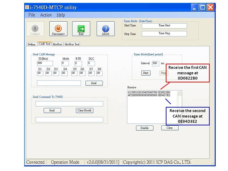
36 How to test the module transmission performance The following procedure will guide you to learning how to transmit/receive CAN messages to/from other devices/pcs by using the I-7540D converter. 1. Connect the I-7540D-MTCP s CAN port into the CAN network, which must at least have one CAN device on the network. 2. Supply the 10~30 volts DC source into the I-7540D-MTCP module through the power terminal. 3. The I-7540D-MTCP module s Power LED will flash approximately once per second. And the 5-digits 7-segment LED will scroll to display some messages. That means the I-7540D-MTCP is working in the operation mode. 4. Run the I-7540D-MTCP Utility software after they have made a wire connection between the PC and the I-7540D-MTCP via the network cable 5. Click the Connect icon on the I-7540D-MTCP Utility tool bar. The setting frame will be popped up. Key-in the IP of the I-7540D- MTCP and press the Connect button in order to connect with it. As shown in the following figure. 6. Select the CAN Test tab in order to test the function of transmission and reception via the I-7540D-MTCP module. In Send CAN Message frame, user can send the necessary CAN message to Ethernet port of 7540D-MTCP. Then 7540D- MTCP will transfer and transmit this message to CAN bus. In the Send Command to 7540D-MTCP frame, users can send command to 7540D-MTCP for getting or setting the status or parameters of 7540D-MTCP. 36

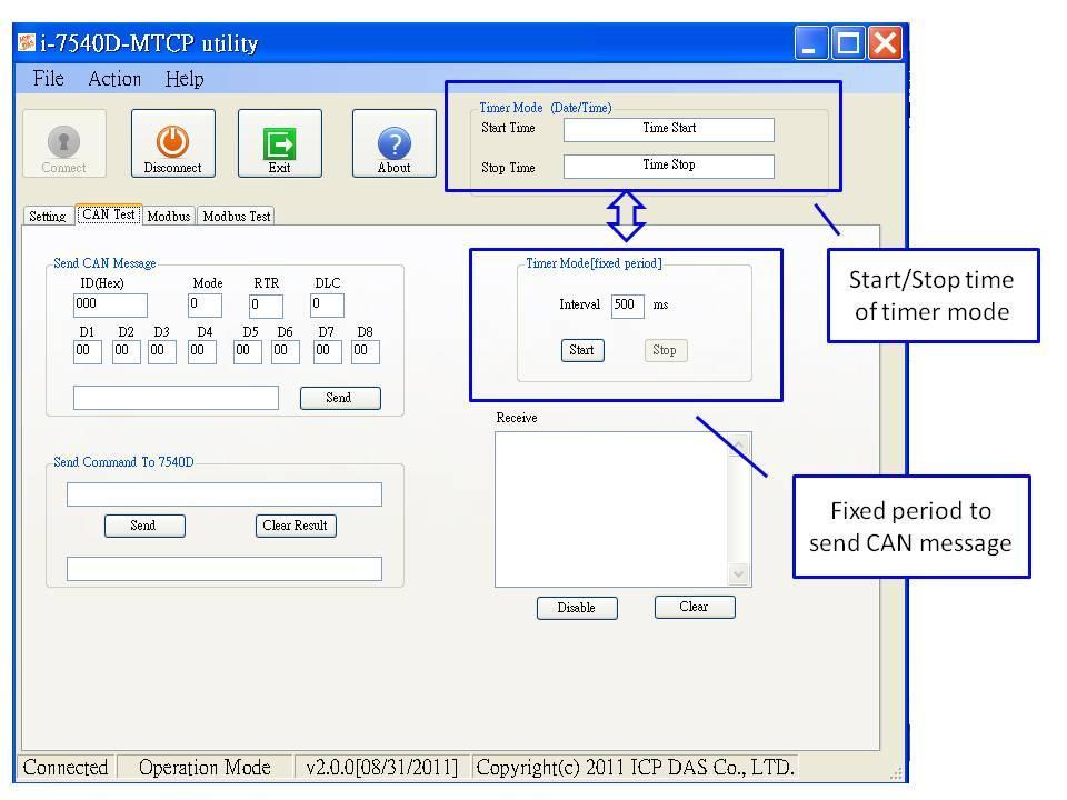
37 7. Users also can use the timer mode to send CAN message in fixed period. And the start/stop time would be displayed in Date/Time format. And when receiving correct CAN message, these CAN message will be displayed on the Receive box. 37
38 38

39 3.1.8 How to use CAN Bus Pair Connection The I-7540D-MTCP supports CAN bus pair connection UDP/TCP function. CAN bus pair connection will use UDP method (port: 57540) or TCP method (port: 10003). User can refer the following application to use this function. Note: After setting Enable CAN Bus Pair Connection, all data send to this I- 7540D-MTCP via Ethernet port will become no effective. 39

40 Application 01: one-to-one communication After setting CAN Bus Pair connection Status of the two I-7540D- MTCP and re-start the system of them, CAN messages between CAN Network 01 and CAN Network 02 can be exchanged by UDP/IP protocol through Ethernet network. Note: When setting to use UDP method, the Server/Client parameters will be no effective. 40

41 Application 02: one-to-many communication (broadcast) 1. After setting CAN Bus Pair connection Status of these I-7540D- MTCP and re-start the system of them, CAN messages on CAN Network 01 will be sent to CAN Network 02 and CAN Network 03 by using UDP/IP protocol via Ethernet network. 2. All CAN message on CAN Network 02 will sent to CAN Network 01 by using UDP/IP protocol via Ethernet network. 3. All CAN message on CAN Network 03 will sent to CAN Network 01 by using UDP/IP protocol via Ethernet network. 4. By using this broadcast method, users need to know how to set the network mask of the I-7540D-MTCP. Note: When setting to use UDP method, the Server/Client parameters will be no effective. 41

42 Application 03: One acts as a server, the other acts as a client. After setting CAN Bus Pair connection Status of the two I-7540D- MTCP and re-start the system of them, CAN messages between CAN Network 01 and CAN Network 02 can be exchanged by TCP/IP protocol through Ethernet network. Note: When setting to act as a TCP server, the Connect to (Destination IP) will be no effective. 42

43 3.1.9 How to set specific CAN ID table When users select the Modbus TCP or Modbus RTU mode, the functions, Device ID and Specific CAN ID, are useful. In the Specific CAN ID field, users can set maximum thirty CAN IDs which indicate the corresponding CAN messages to be stored in the specific Modbus Input Register respectively. In the Modbus Input Register, the register range of the Specific CAN ID occupies the section from 0x0E10 to 0x102C. Each CAN ID will use 18 Modbus input registers. In Modbus TCP/ RTU mode, users need to communicate the I- 7540D-MTCP with Modbus TCP/RTU command. The I-7540D-MTCP only supports function code 0x03/0x04/0x10 of Modbus TCP/RTU commands for reading and writing CAN messages. 43
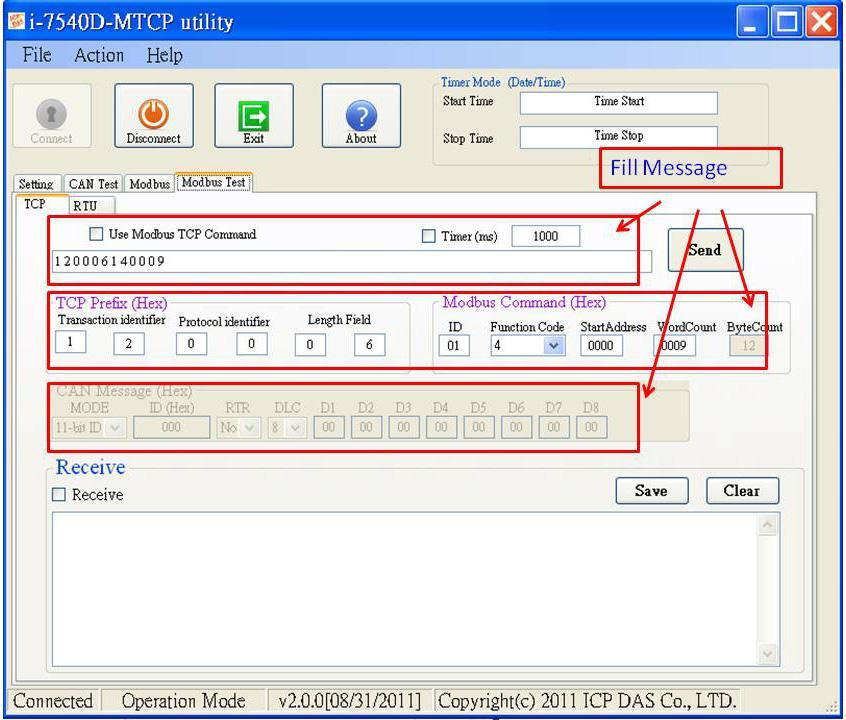
44 How to test Modbus TCP mode In this mode, there are two methods for users to send command to the I-7540D-MTCP. The screenshot of the Utility is shown below: Through the first method (check Use Modbus TCP Command ) users can use the function code 0x03/0x04/0x10 of Modbus TCP commands for reading and writing CAN message. The second method (uncheck Use Modbus TCP Command ) requires users to understand the Modbus TCP protocol. Then key-in the correct Modbus TCP command in the text box. Both of the methods require users to click the Send button to transmit the command to the I-7540D-MTCP module. When checking the Timer(ms), the Utility will transmit the command periodically. If the Receive is checked, the messages sent from the I-7540D- MTCP will automatically be received and displayed in the Receive text box. Besides, users can click the Clear button to remove the messages on the text box. In addition, users can click the Save button to save the messages in the Receive text box into the I-7540D- MTCP_MT_yyyyMMddmmss.txt file. The indication of the file name is described below. 44
45 45
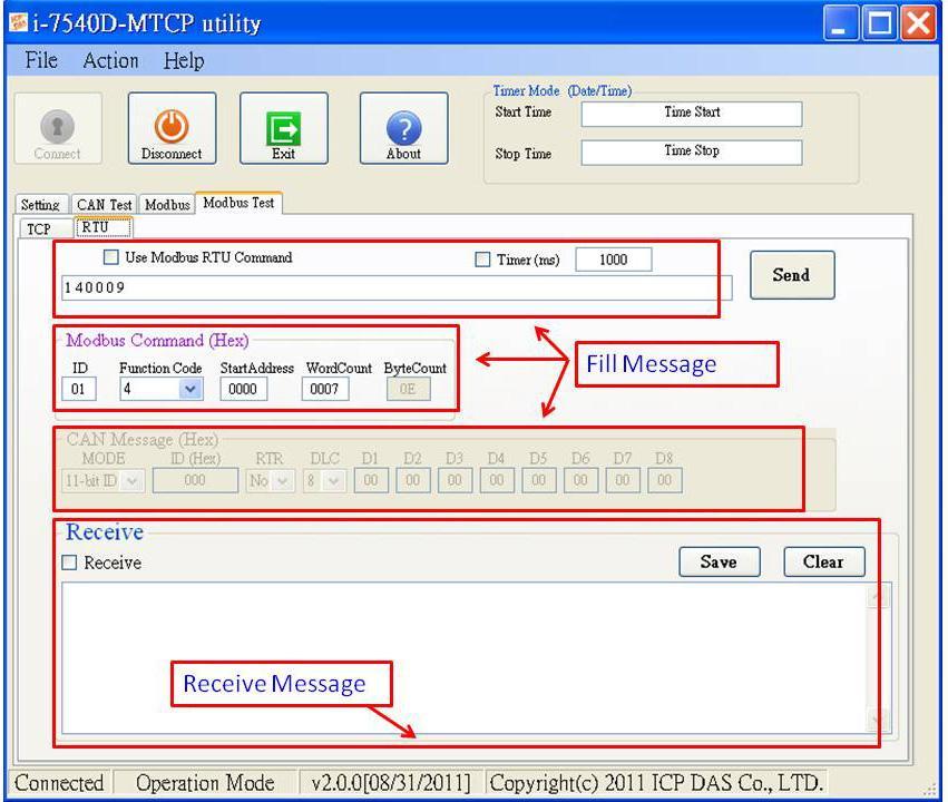
46 How to test Modbus RTU mode In this mode, there are two methods for users to send command to the I-7540D-MTCP. The screenshot of the Utility is shown below: Through the first method (check Use Modbus RTU Command ) users can use the function code 0x03/0x04/0x10 of Modbus RTU commands for reading and writing CAN message. The second method (uncheck Use Modbus RTU Command ) requires users to understand the Modbus RTU protocol. Then key-in the correct Modbus RTU command in the text box. Both of the methods require users to click the Send button to transmit the command to the I-7540D-MTCP module. When checking the Timer(ms), the Utility will transmit the command periodically. If the Receive is checked, the messages sent from the I-7540D- MTCP will automatically be received and displayed in the Receive text box. Besides, users can click the Clear button to remove the messages on the text box. In addition, users can click the Save button to save the messages in the Receive text box into the I-7540D- MTCP_MR_yyyyMMddmmss.txt file. The indication of the file name is described below. 46
47 47
48 3.2 MiniOS7 Utility MiniOS7 Utility is a tool for configuring, uploading files to all products embedded with ICPDAS MiniOS7. And it provides some PC diagnostic tools which can help users to diagnose the status of the I-7540D-MTCP and other controllers. Supported connection ways COM Port Connection Ethernet UDP & TCP Connection Maintenance Upload file(s) Update MiniOS7 image Delete file(s) Configure Date & Time IP Address COM port Check Product information 48
49 3.2.1 Install the MiniOS7 Utility Step 1: The installation software can be obtained from the following location. 8000cd:\\Napdos\MiniOS7\utility\MiniOS7_utility\ or Step 2: Go to where you downloaded the file, and double-click on the installation file in Windows to execute it. Step 3: To finish the installation of the MiniOS7 Utility, click the Finish button to exit the setup process. 49

50 3.2.2 PC Diagnostic tools The MiniOS7 Utility provides serial PC diagnostic tools. These PC diagnostic tools can be opened from the Tools menu of MiniOS7 Utility. The PC Diagnostic tools include: 7188XW: 7188XW is the PC side utility for modules using the ICPDAS MiniOS7. It is the Win32 version of 7188x.exe. For 7188x.exe just can use the standard COMPORT(RS-232) of PC,ButonWin32systems (WIN95/98/ME/NT/2K/XP) also have RS-232 port use PCMCIA or USB interface, 7188x.exe can not use these devices, so need the program 7188xw.exe. Using RS-232 ports of PC link to the modules using MiniOS7.7188xw.exe in basically is a terminal program. It sends out the data that user key-in to COM port, and show the data received from COM port on the screen of PC. The main function for 7188xw.exe is to DOWNLOAD files to the MiniOS7 system. 50

51 Send232: Send232 uses serial port (RS-232) interface to communicate with devices. And it can be used to test the Virtual COM technology. 51


52 SendTCP: SendTCP uses TCP protocol to communicate with the 7188E/8000E/7540D/7540D-MTCP and other devices from Ethernet. Step 1: Run SendTCP in host-pc. Step 2: Input the IP of I-7540D-MTCP and press the Connect button to connect with I-7540D-MTCP. And then it will display 7188E3 is connected. 52


53 Step 3: Send command 10 to the I-7540D. And it will response 7188E3 message. Step 4: Select Port 2 and CR. Then send $02M to read 7000 module s ID which is connected to I-7540D-MTCP s COM2. If you enable 7000 module s checksum function, select CS_CR. The CS_CR option will add two checksum bytes, then adds CR. 53

54 Step 5: If you want to change the 7540D-MTCP s COM ports settings, click Set to change them. The 7540D-MTCP s COM port that you want to configure is specified by Select Port combo list. Port 2 means you want to configure the 7188E s COM2. 54

55 7188E: Command-prompt mode program, used to send data to specific machines using TCP protocol. Usage: 7188e [-S:IP] [-P:Port]: Connect to a device by using TCP protocol. *Q: Quit program and disconnect. 55
56 4. Support Command List For easy application, we provide 4 command strings to allow users to send specific commands from I-7540D-MTCP s Ethernet port10003 to CAN bus. And receiving response message form CAN bus. Also, we provide several commands for I-7540D-MTCP s Ethernet port10000 to set and get the status of 7540D-MTCP. It can cover most applications of different requests. The general formats of the I-7540D-MTCP s commands are given below: Port Command Format: <Command><CR> <Command> : The commands of the I-7540D-MTCP. <CR> : All commands from this port must end with the character <CR> (The ASCII value is 13). The 4 command formats are given in the following table. More detailed information related to the each command will be described in the following sub sections. Table 4-1: Command list table (port 10003) Command Description tiiildd <CR> Send or receive a standard data frame. TIIIL<CR> Send or receive a standard remote frame. eiiiiiiiildd <CR> Send or receive an extended data frame. EIIIIIIIIL<CR> Send or receive an extended remote frame. Note: The I-7540D-MTCP s COM3 (CAN port) can only accept these 4 commands. 56
57 Port Command Format: 99<Command> 99 : Specific command for getting or setting the status of the 7540D-MTCP Table 4-2: Command list table (port 10000) Command Description S Read the status value of I-7540D C Clear CAN error flag and FIFO RA Reboot the I-7540D module. #P01 Read the RS-232 configuration #P02 Read the RS-485 configuration #P1 Read the CAN configuration #P1B Read the BTR0 and BTR1 configuration $P0105BBDSP Change the RS-232 configuration $P0205BBDSP Change the RS-485 configuration $P114PBCC MM ET Change the CAN configuration $P1B04TTRR Change the BTR0 and BTR1 configuration #PWID Read Web ID configuration #PWPW Read Web Password configuration $PWIDLLxxxxx Change Web ID configuration $PWPWLLxxxxx Change Web Password configuration #PPC Read CAN Pair Connection configuration #PPIP Read CAN Pair Destination IP $PPCLLABC Change CAN Pair Connection configuration $PPIPxxx Change CAN Pair Destination IP Note: 1. More detailed information related to of the each command will be described in the following sub sections. 2. The #P1B and $P1B04TTRR commands just can be used on the firmware version v1.04 or later. 3. The #PWID, #PWPW, $PWIDLLxxxxx, $PWPWLLxxxxx, commands just can be used on the firmware version v1.05 or later. 4. The #PPC, #PPIP, $PPCLLABC, $PPIPxxx commands just can be used on the firmware version v1.06 or later. 57
58 4.1 tiiildd <CR> Description: Send or receive a standard CAN data frame. Syntax: tiiildd <CR> t Represent a standard (2.0A) data frame. III 11 bits Identifier (000~7FF) L Data length (0~8) DD Input data frame value according to the data length (00~FF) Response: Valid command: No response Invalid command:?<error Code><CR> Note: It is necessary to enable the Error Response function in the I-7540D-MTCP Utility, in order to receive Syntax and/or communication error information at the host PC. Example: Command: t03f <cr> Send a CAN message with a standard data frame. ID=03F, DLC=6, data1=11, data2=22, data3=33, data4=44, data5=55 and data6=66. Note: This command can only be accepted by 7540D-MTCP s port
59 4.2 TIIIL<CR> Description: Send or receive a standard CAN remote frame. Syntax: TIIIL<CR> T Represents a standard (2.0A) remote frame. III 11 bits Identifier (000~7FF) L Data length (0~8) Response: Valid command: No response Invalid command:?<error Code><CR> Note: It is necessary to enable the Error Response function in the I-7540D-MTCP Utility, in order to receive Syntax and/or communication error information at the host PC. Example: Command: T2E88<CR> Send a CAN message with a standard remote frame. ID=2E8, DLC=8. Note: This command can only be accepted by 7540D-MTCP s port
60 4.3 eiiiiiiiildd <CR> Description: Send or receive an extended CAN data frame. Syntax: eiiiiiiiildd <CR> e Stands for the extended (2.0B) data frame. IIIIIIII 29 bits Identifier ( ~1FFFFFFF) L Data length (0~8) DD Input data frame value according to the data length (00~FF) Response: Valid command: No response Invalid command:?<error Code><CR> Note: It is necessary to enable the Error Response function in the I-7540D-MTCP Utility, in order to receive Syntax and/or communication error information at the host PC.. Example: Command: e <cr> Send a CAN message with an extended data frame. ID= , DLC=5, data1=11, data2=22, data3=33, data4=44 and data5=55. Note: This command can only be accepted by 7540D-MTCP s port
61 4.4 EIIIIIIIIL<CR> Description: Send or receive an extended CAN remote frame. Syntax: EIIIIIIIIL<CR> E Stands for the extended (2.0B) CAN remote frame. IIIIIIII 29 bits Identifier ( ~1FFFFFFF) L Data length (0~8) Response: Valid command: No response Invalid command:?<error Code><CR> Note: It is necessary to enable the Error Response function in the I- 7540D Utility, in order to receive Syntax and/or communication error information at the host PC. Example: Command: E <CR> Send a CAN message with an extended remote frame. ID= , DLC=6. Note: This command can only be accepted by 7540D-MTCP s port
62 4.5 99S Description: Read the I-7540D CAN Baud Rate and error flag message. Syntax: 99S 99S Command character Response: Valid Command:!CFFTTRRO<CR> Invalid command:?<error Code><CR>! Delimiter for valid command C current baud rate setting of CAN FF CAN status register TT CAN transmit error counter RR CAN receive error counter O CAN or RS-232/485/422 FIFO Overflow flag Note: Furthermore, all response results are shown in the ASCII format. Users need to make an ASCII to hex format transformation in order to understand what the meaning is based on the 4-2, 4-3, 4-4 tables Table 4-3: CAN baud rate list AsciiToHex(C) Description 0 10K baud rate of CAN 1 20K baud rate of CAN 2 50K baud rate of CAN 3 100K baud rate of CAN 4 125K baud rate of CAN 5 250K baud rate of CAN 6 500K baud rate of CAN 7 800K baud rate of CAN K baud rate of CAN 9 User defined 62
63 Table 4-4: CAN status register list AsciiToHex(FF) Name Value Function Bus-off; the SJA100 is not involved in 1 bus activities Bit 7 (MSB) Bus Status Bus-on; the SJA1000 is involved in 0 bus activities Error; at least one of the error 1 counter has reached or exceeded the Bit 6 Error Status CPU warning limit Ok; both error counters are below the 0 warning limit Transmit; the SJA1000 is transmitting 1 a message Bit 5 Transmit Status Idle; no transmit message is in 0 progress Receive; the SJA1000 is receiving a 1 message Bit 4 Receive Status Idle; no receive message is in 0 progress Complete; the previously requested Transmission 1 transmission is not yet completed Bit 3 Complete Status Incomplete; the previously requested 0 transmission is not yet complement Released; the CPU may write a Transmit Buffer 1 message into the transmit buffer Bit2 Status Locked; a message is waiting for 0 transmission or is already in process Data Overrun 1 Overrun; a message was lost Bit 1 Status Absent; no data overrun has 0 occurred Full; one or more messages are Receive Buffer 1 Bit 0 (LSB) available in the RXFIFO Status 0 Empty; no message is available AsciiToHex(O) Bit 3 =1 Bit 2 =1 Bit 1 =1 Bit 0 =1 Table 4-5: CAN Error flag list Description CAN Transmit Error CAN Receive Error CAN FIFO Overflow Initial CAN Chip Error 63
64 Example: Command: 99S Receive:!40C00000<CR> Obtain some current information on the I-7540D-MTCP module. The response will show the following results: CAN baud rate=125k, CAN status register= transmission complete and transmit buffer is released, CAN transmit error counter=0, CAN receive error counter=0 and CAN FIFO = normal. Note: This command can only be accepted by 7540D-MTCP s port
65 4.6 99C Description: Clear the CAN error flag and FIFO on the module. Syntax: 99C 99C Command character Response: Valid Command: No response. Invalid command: ERROR Note: After sending this command, the CAN receive and transmit FIFO will be clear. The error counter of reception and transmission will be set to zero. And the TX and RX LEDs will turn OFF. Example: Command: 99C Note: This command can only be accepted by 7540D-MTCP s port
66 4.7 99RA Description: Reboot the I-7540D-MTCP module. Users can use this command to reboot the module in order to allow it to work in order again. Syntax: 99RA 99RA Command character Response: Valid Command: Reboot the I-7540D-MTCP module. Invalid command: ERROR Example: Command: 99RA The I-7540D-MTCP module will reboot after it had received this command. Note: This command can only be accepted by 7540D-MTCP s port
67 4.8 99#P01 Description: Read the RS-232 configuration Syntax: 99#P01 99#P01 Command character Response: Valid Command: 061BBDSP Invalid command: ERROR 061 Delimiter for valid command BB RS-232 Baud rate D Data bit 0 = 7 bits data formation 1 = 8 bits data formation S Stop bit 0 = 1 stop bit 1 = 2 stop bits P Parity bits 0 = None 1 = Even 2 = Odd RS-232 Baud rate list BB Description bps baud rate of RS bps baud rate of RS bps baud rate of RS bps baud rate of RS bps baud rate of RS bps baud rate of RS bps baud rate of RS bps baud rate of RS bps baud rate of RS bps baud rate of RS-232 0A bps baud rate of RS-232 0B bps baud rate of RS
68 Example: Command: 99#P01 Response: 0610B100 The response will show the following results: RS-232 baud rate=115.2k bps, data bits=8, stop bits=1, none parity. Note: This command can only be accepted by 7540D-MTCP s port
69 4.9 99#P02 Description: Read the RS-485 configuration. Syntax: 99#P02 99#P02 Command character Response: Valid Command: 062BBDSP Invalid command: ERROR 062 Delimiter for valid command BB RS-485 Baud rate D Data bit 0 = 7 bits data formation 1 = 8 bits data formation S Stop bit 0 = 1 stop bit 1 = 2 stop bits P Parity bits 0 = None 1 = Even 2 = Odd RS-485 Baud rate list BB Description bps baud rate of RS bps baud rate of RS bps baud rate of RS bps baud rate of RS bps baud rate of RS bps baud rate of RS bps baud rate of RS bps baud rate of RS bps baud rate of RS bps baud rate of RS-485 0A bps baud rate of RS-485 0B bps baud rate of RS
70 Example: Command: 99#P02 Response: The response will show the following results: RS-485 baud rate=9600 bps, data bits=8, stop bits=2, even parity. Note: This command can only be accepted by 7540D-MTCP s port
71 #P1 Description: Read the CAN configuration. Syntax: 99#P1 99#P1 Command character Response: Valid Command: 14PBCCCCCCCCMMMMMMMMET Invalid command: ERROR 14 Delimiter for valid command P CAN specification 0 = 2.0A 1 = 2.0B B CAN Baud rate CCCCCCCC 32 bits Acceptance Code Register ( ~FFFFFFFF) MMMMMMMM 32 bits Acceptance Mask Register ( ~FFFFFFFF) E Error response or not 0 = Disable 1 = Enable T Timestamp response or not 0 = Disable 1 = Enable CAN Baud rate list B Description 0 10K baud rate of CAN 1 20K baud rate of CAN 2 50K baud rate of CAN 3 100K baud rate of CAN 4 125K baud rate of CAN 5 250K baud rate of CAN 6 500K baud rate of CAN 7 800K baud rate of CAN K baud rate of CAN 9 User Defined 71
72 Example: Command: 99#P1 Response: FFFFFFFF00 The response will show the following results: CAN specification=2.0a, CAB baud rate=125kbps, acceptance code register= , acceptance mask register=ffffffff, disable error response, disable timestamp. Note: This command can only be accepted by 7540D-MTCP s port
73 99#P1B Description: Read the CAN Bus Timing Register Syntax: 99#P1B 99#P1B Command character Response: Valid Command: 06PBTTRR Invalid command: ERROR 06 Delimiter for valid command P CAN specification 0 = 2.0A 1 = 2.0B B CAN Baud rate TT CAN Bus Timing Register 1 (00~FF) RR CAN Bus Timing Register 1 (00~FF) CAN Baud rate list B Description 0 10K baud rate of CAN 1 20K baud rate of CAN 2 50K baud rate of CAN 3 100K baud rate of CAN 4 125K baud rate of CAN 5 250K baud rate of CAN 6 500K baud rate of CAN 7 800K baud rate of CAN 8 10K baud rate of CAN 9 User defined Example: Command: 99#P1B Response: The response will show the following results: CAN specification = 2.0A, CAN baud rate = User defined, BTR0=00, BTR1=14. Note: This command can only be accepted by 7540D-MTCP s port
74 $P0105BBDSP Description: Change the RS-232 configuration of the I-7540D-MTCP. Syntax: 99#P0105BBDSP 99#P0105 Command character BB RS-232 Baud rate D Data bit 0 = 7 bits data formation 1 = 8 bits data formation S Stop bit 0 = 1 stop bit 1 = 2 stop bits P Parity bits 0 = None 1 = Even 2 = Odd RS-232 Baud rate list BB Description bps baud rate of RS bps baud rate of RS bps baud rate of RS bps baud rate of RS bps baud rate of RS bps baud rate of RS bps baud rate of RS bps baud rate of RS bps baud rate of RS bps baud rate of RS-232 0A bps baud rate of RS-232 0B bps baud rate of RS-232 Response: Valid Command: OK Invalid command: ERROR Example: Command: 99#P01050B100 Response: OK Set the setting of RS-232 baud rate= 115.2Kbps, data bits=8, stop 74
75 bit=1, none parity bit into the I-7540D-MTCP and the 7540D- MTCP response OK command to mean that the configuration of RS-232 has been changed. Note: This command can only be accepted by 7540D-MTCP s port
76 $P0205BBDSP Description: Change the RS-485 configuration of the I-7540D-MTCP. Syntax: 99#P0205BBDSP 99#P0205 Command character BB RS-485 Baud rate D Data bit 0 = 7 bits data formation 1 = 8 bits data formation S Stop bit 0 = 1 stop bit 1 = 2 stop bits P Parity bits 0 = None 1 = Even 2 = Odd Response: Valid Command: OK Invalid command: ERROR RS-485 Baud rate list BB Description bps baud rate of RS bps baud rate of RS bps baud rate of RS bps baud rate of RS bps baud rate of RS bps baud rate of RS bps baud rate of RS bps baud rate of RS bps baud rate of RS bps baud rate of RS-485 0A bps baud rate of RS-485 0B bps baud rate of RS-485 Example: Command: 99#P02050B100 Response: OK Set the setting of RS-485 baud rate= 115.2Kbps, data bits=8, stop 76
77 bit=1, none parity bit into the I-7540D-MTCP and the 7540D- MTCP response OK command to mean that the configuration of RS-485 has been changed. Note: This command can only be accepted by 7540D-MTCP s port
78 $P114PBCC MM ET Description: Change the CAN configuration of the I-7540D-MTCP Syntax: 99#P114PBCC MM ET 99#P114 Command character P CAN specification 0 = 2.0A 1 = 2.0B B CAN Baud rate CCCCCCCC 32 bits Acceptance Code Register ( ~FFFFFFFF) MMMMMMMM 32 bits Acceptance Mask Register ( ~FFFFFFFF) E Error response or not 0 = Disable 1 = Enable T Timestamp response or not 0 = Disable 1 = Enable Response: Valid Command: OK Invalid command: ERROR CAN Baud rate list B Description 0 10K baud rate of CAN 1 20K baud rate of CAN 2 50K baud rate of CAN 3 100K baud rate of CAN 4 125K baud rate of CAN 5 250K baud rate of CAN 6 500K baud rate of CAN 7 800K baud rate of CAN 8 10K baud rate of CAN 9 User defined Example: Command: 99#P FFFFFFFF00 Response: OK 78
79 Set the setting of CAN specification=2.0a, CAN baud rate= 125 Kbps, acceptance code= , acceptance mask=ffffffff, disable error response, disable timestamp response into the I- 7540D and the 7540D response OK command to mean that the configuration of CAN has been changed. Note: This command can only be accepted by 7540D-MTCP s port
80 $P1B04TTRR Description: Change the CAN Bus Timing Register of the I-7540D- MTCP Syntax: 99#P1B04TTRR 99#P1B04 TT RR Command character Bus Timing Register 0 (00~FF) Bus Timing Register 1 (00~FF) Response: Valid Command: OK Invalid command: ERROR Note: 1. This command can only be accepted by 7540D-MTCP s port Users need to have the background of SJA1000 CAN controller and 82C251 CAN transceiver, and calculate the values of BT0 and BT1 by themselves (The clock frequency of CAN controller is 16MHz.). 80
81 #PWID Description: Read the Wed ID configuration Syntax: 99#PWID 99#PWID Command character Response: Valid Command: LLxxxxx Invalid command: ERROR LL xxxxx Web ID Length, in hexadecimal format. Web ID saved in the EEPROM, the default Web ID setting is I7540D Example: Command: 99#PWID Response: D Read the Web ID setting of the 7540D-MTCP, and the 7540D- MTCP responses the Web ID setting is 7540D. Note: This command can only be accepted by 7540D-MTCP s port
82 #PWPW Description: Read the Wed Password configuration Syntax: 99#PWPW 99#PWPW Command character Response: Valid Command: LLxxxxx Invalid command: ERROR LL xxxxx Web ID Length, in hexadecimal format. Web ID saved in the EEPROM, the default Web ID setting is I7540D Example: Command: 99#PWPW Response: 0Bicpdas7540D Read the Web password setting of the 7540D-MTCP, and the 7540D-MTCP responses the Web password setting is icpdas7540d. Note: This command can only be accepted by 7540D-MTCP s port
83 $PWIDLLxxxxx Description: Change the Wed ID configuration. Syntax: 99#PWIDLLxxxxx 99#PWID LL xxxxx Command character Web ID data Length, in hexadecimal format. Web ID data, at most 30 ASCII characters. Response: Valid Command: OK Invalid command: ERROR Example: Command: 99#PWID Response: OK Change the Web ID data setting of the 7540D-MTCP to 7540 and the 7540D-MTCP responses OK command to mean that the configuration of Web ID data has been changed. Note: This command can only be accepted by 7540D-MTCP s port
84 $PWPWLLxxxxx Description: Change the Wed password configuration. Syntax: 99#P02 99#PWPW LL xxxxx Command character Web password data Length, in hexadecimal format. Web password data that you want to configure. At most 30 ASCII characters. Response: Valid Command: OK Invalid command: ERROR Example: Command: 99#PWPW Response: OK Change the Web password data setting of the 7540D-MTCP to and the 7540D-MTCP responses OK command to mean that the configuration of Web ID data has been changed.. Note: This command can only be accepted by 7540D-MTCP s port
85 #PPC Description: Read the CAN bus pair connection configuration. Here support three parameters, enable can pair, TCP or UDP and Server or Client Syntax: 99#PPC 99#PPC Command character Response: Valid Command: LLABC Invalid command: ERROR LL A B C number of parameters Enable CAN bus pair connection flag, 0: Disable, 1: Enable Using TCP or UDP connection; 0: TCP, 1: UDP Act as a server or client; 0: server, 1: client Example: Command: 99#PPC Response: Read the CAN bus pair connection configuration of the 7540D- MTCP, and the 7540D-MTCP responses that enable can bus pair connection and act as a TCP server. Note: This command can only be accepted by 7540D-MTCP s port
86 #PPIP Description: Read the destination IP of CAN bus pair connection. Syntax: 99#PPIP 99#PPIP Command character Response: Valid Command: xxx.xxx.xxx.xxx Invalid command: ERROR xxx.xxx.xxx.xxx Destination IP Address. Example: Command: 99#PPIP Response: Read the CAN bus pair connection destination IP of the 7540D- MTCP, and the 7540D-MTCP responses that destination IP address is Note: This command can only be accepted by 7540D-MTCP s port
87 $PPCLLABC Description: Change the CAN bus pair connection configuration. After setting successfully, all parameters will take effective after system restart. Syntax: 99#PPCLLABC 99#PPC Command character LL number of parameters, here fix to 03 A Enable CAN bus pair connection flag, 0: Disable, 1: Enable B Using TCP or UDP connection; 0: TCP, 1: UDP C Act as a server or client; 0: server, 1: client Note: 1. When A=0, B and C take no effective 2. When using UDP connection (B=1), C take no effective 3. When acting as a TCP client or using UDP method, users need to set the destination IP address (section 4.23), so that the 7540D-MTCP can work correctly. Response: Valid Command: OK Invalid command: ERROR Example: Command: 99#PPC03101 Response: OK Change the CAN bus pair connection configuration of the 7540D- MTCP to enable CAN bus pair connection and act as a TCP client.. Note: This command can only be accepted by 7540D-MTCP s port
88 $PPIPxxx Description: Change the CAN bus pair connection destination IP address. After setting successfully, all parameters will take effective after system re-start Syntax: 99#PPIPxxx 99#PPIP Command character xxx IP address, iii/ppp/iii/ppp: 3 digits number Note: This IP address is effective when enable CAN bus pair connection and acting as TCP client or using UDP connection method. Response: Valid Command: OK Invalid command: ERROR Example: Command: 99#PPIP Response: OK Change the CAN bus pair connection destination IP of the 7540D- MTCP. Note: This command can only be accepted by 7540D-MTCP s port
89 4.23 General Error code for commands from port Table 4-6: Error code table AsciiToHex Description (Error code) The head character of the command string is 1 invalid. 2 The length of the command string is invalid. 3 The value of CAN identifier is invalid. 4 The value of CAN data length is invalid. 5 Reserved 89
90 5. Modbus Network (Only for Modbus TCP/ Modbus RTU mode) The I-7540D-MTCP, Modbus TCP / Modbus RTU to CAN converter, supports the Modbus TCP/ Modbus RTU protocol. It acts as a Modbus TCP server / Modbus RTU slave device on the Modbus network. There are some mechanisms for data-exchanging between the CAN register and the Modbus register as the figure at the following section. In the Modbus Input Register, according to the different purposes these register are divided into three fields, Normal CAN Message Field, Specific CAN Message Field and Module Status Field. When a CAN message received from the CAN network, the I-7540D-MTCP will check if the Specific CAN Message filed is used or not. If it is not used, this CAN message will be stored into the Normal CAN Message field. This field is similar with a kind of FIFO (first-in first-out buffer). Users can only read this field with the start address of this field by applying the Modbus command. It only supports the FIFO read method. After users read the CAN messages from this field, the rest unread CAN messages will be moved to the buffer with the start address of this field. This field can store maximum 200 CAN messages. Therefore, if the unread CAN messages exceed 200 records, the data will be lost. If the Specific CAN Message Field is used, the CAN messages which are marked in the specific CAN message table of the Utility tool are directly moved to the Specific CAN Message Field. CAN messages with different CAN IDs will be stored in different parts of the Specific CAN Message field. Users can set maximum 30 different CAN ID of CAN messages. Besides, a kind of CAN ID only has one record buffer. If there are two CAN messages with the same ID, the later will over-write the former. Therefore, the Specific CAN Message filed always keeps the newest information of the corresponding CAN messages with the specific CAN IDs. If a CAN message is sent to a CAN network from a Modbus network via the I-7540D-MTCP, the CAN message will be temporarily stored in Output Register and not be transmitted until the CAN bus idle. The Output Register is only one message buffer. Users can also use Modbus command to read the CAN message transmitted before. It is helpful for checking the last sent record. 90

91 Figure 5-1: CAN message Format of I-7540D-MTCP Modbus mode. 91
92 5.1 Supported Modbus Functions The Modbus function codes supported by the I-7540D-MTCP are shown in the following table. Table 5-1: Supported Modbus Function Codes Function Code Function Name Description Read multiple registers 3 (03 Hex) Reading Output Register (4x) for a sent CAN messages Read multiple input 4 (04 Hex) Reading Input Register registers (3x) for reading CAN messages Write multiple registers 16 (10 Hex) Preset Multiple Registers (4x) for sending a CAN message 92
 Normal CAN Message Field: In this field, the address range of Normal CAN Message is 0x0000~0x0E0F. It is used to store the CAN message received from the CAN network.")
93 5.2 Modbus TCP Address Figure 5-2: The address definition of Input Register and Output Register of the I-7540D-MTCP. Modbus Input Register: (1) Normal CAN Message Field: In this field, the address range of Normal CAN Message is 0x0000~0x0E0F. It is used to store the CAN message received from the CAN network. One CAN message will occupy 18-byte address space in the Normal CAN Message field. Therefore, it can store maximum 200 CAN messages. The detailed Modbus address arrangement of Normal CAN Message field is described as the table 5-2. Modbus Address Word Count Description 0x0000 ~ 0x RX CAN Message #001 0x0012 ~ 0x RX CAN Message #002 0x0DEC ~ 0x0DFD 9 RX CAN Message #199 0x0DFE ~ 0x0E0F 9 RX CAN Message #200 Table5-2: Modbus address arrangement of Normal CAN Message field. (2) Specific CAN Message Field: The I-7540D-MTCP supports a Specific CAN Message field to store thirty special CAN messages with specific the CAN IDs. 93
94 When the I-7540D-MTCP receives the CAN messages whose CAN IDs are defined in the Specific CAN Message Field by the Utility tool, the I-7540D-MTCP put this CAN message into the corresponding register of the Specific CAN Message field. Each CAN message will occupy 18 address space of the register, and the range of this field is listed in following table. Modbus Address Word Count Description 0x0E10~0x0F21 9 Specific RX CAN Message #01 0x0FFF~0x Specific RX CAN Message #29 0x101A~0x102B 9 Specific RX CAN Message #30 Table5-3: Modbus address of Specific CAN Message field. (3) Module Status Field: The I-7540D-MTCP s status information is defined in the following address. Users can use the Modbus RTU command (function code 04 hex ) to read these information from the Module Status field. Modbus Address Byte Count Description 0x102C 1 current baud rate setting of CAN 0x102D 1 CAN status register 0x102E 1 CAN transmit error counter 0x102F 1 CAN receive error counter 0x CAN or RS-232/485/422 FIFO Overflow flag 0x1031~0x103E 13 No used Table5-4: Modbus address of Modbus Status field. Note: The meaning of the register values can refer to section
 received from the CAN network will be stored into the Normal CAN Message field.")
95 5.2.1 Using Modbus TCP command to get a CAN Message When the I-7540D-MTCP is set to the Modbus TCP mode, each CAN message (except the CAN message whose CAN IDs are defined in the Specific CAN Message field) received from the CAN network will be stored into the Normal CAN Message field. Users can use the Modbus TCP command (function code 04 hex ) to read the CAN message from the Normal CAN Message field (refer to table 5-2). The start address of each command must be set to 0000 hex and the data length field must be 7 or 9 (with Timestamp) because one CAN message uses 7 or 9 address space. After reading the registers by the Modbus command, the content of the registers of the read CAN message is covered by the unread CAN message which will be read next. Example: Use Modbus TCP command (function code 04 hex ) to read one CAN message: Figure 5-3: Use the Modbus TCP command to read one CAN message. 95
96 5.2.2 Using Modbus TCP command to Send a CAN Message If users need to send CAN messages via the Modbus TCP commands, users need to send the Modbus TCP command with the TX CAN message format to the Output Register of the I-7540D-MTCP. Then the I-7540D-MTCP will transfer this command to a CAN message format and send it to the buffer of the CAN controller. The CAN controller will send the CAN message automatically which the CAN bus is idle. Users can use Modbus TCP commands (function code 10 hex ) to transmit a CAN message by writing the Output Register of the I-7540D- MTCP (the data format must follow the Figure 5-1). The start address of the Modbus TCP command is always 0000 hex, and the Word count and Byte count are always 07 hex and 0D hex respectively. Example: Use the Modbus TCP command (function code 10 hex ) to transmit a CAN message to the CAN network: Users can use the Modbus TCP command with function code 03 hex to read the transmitted CAN message. The start address of the command is always 0000 hex, and the data length field must be set to 0007 hex. 96
 to read the transmitted CAN message format from the Output Register: Figure 5-5: Use the")
97 Figure 5-4: Use Modbus TCP command to transmit a CAN message. Example: Use the Modbus TCP command (function code 03 hex ) to read the transmitted CAN message format from the Output Register: Figure 5-5: Use the Modbus TCP command (function code 03 hex ) to read the transmitted CAN message format. 97
98 5.2.3 Using Modbus TCP command to get a Specific CAN Message The I-7540D-MTCP supports a Specific CAN Message field to get the expect ten specific CAN messages. When receiving a CAN message whose CAN ID is defined in the Specific CAN Message by the Utility tool, the I-7540D-MTCP will save this CAN message to the Specific CAN Message field. Users can use the Modbus TCP command (function code 04 hex ) to directly read the CAN message from this field. It is usually used to get the important CAN messages immediately. The start address of the command must be the same as the start address defined in the Specific CAN Message field, and the data length field must be 7 or 9 (with Timestamp). Example: Use the Modbus TCP command (function code 04 hex) to read the specific CAN message from the Specific CAN Message field: Figure 5-6: Use the Modbus TCP command to read specific CAN message. 98
 received from the CAN network will be stored into the Normal CAN Message field.")
99 5.3 Modbus RTU Address Using Modbus RTU command to get a CAN Message When the I-7540D-MTCP is set to the Modbus RTU mode, each CAN message (except the CAN message whose CAN IDs are defined in the Specific CAN Message field) received from the CAN network will be stored into the Normal CAN Message field. Users can use the Modbus RTU command (function code 04 hex ) to read the CAN message from the Normal CAN Message field (refer to table 5-2.). The start address of each command must be set to 0000 hex and the data length field must be 7 because one CAN message uses 7 address space. After reading the registers by the Modbus command, the content of the registers of the read CAN message is covered by the unread CAN message which will be read next. Example1: Use Modbus RTU command (function code 04 hex ) to read one CAN message: Figure 5-7: Use the Modbus RTU command to read one CAN message. 99

100 5.3.2 Using Modbus RTU command to Send a CAN Message If users need to send CAN messages via the Modbus RTU commands, users need to send the Modbus RTU command with the TX CAN message format to the Output Register of the I-7540D-MTCP. Then the I-7540D-MTCP will transfer this command to a CAN message format and send it to the buffer of the CAN controller. The CAN controller will send the CAN message automatically which the CAN bus is idle. Users can use Modbus RTU commands (function code 10 hex ) to transmit a CAN message by writing the Output Register of the I-7540D- MTCP (the data format must follow the Figure 5-1). The start address of the Modbus command is always 0000 hex, and the Word count and Byte count are always 07 hex and 0D hex respectively. Example: Use the Modbus RTU command (function code 10 hex ) to transmit a CAN message to the CAN network: Figure 5-8: Use Modbus RTU command to transmit a CAN message. 100

101 Users can use the Modbus RTU command with function code 03 hex to read the transmitted CAN message. The start address of the command is always 0000 hex, and the data length field must be set to 0007 hex. Example: Use the Modbus RTU command (function code 03 hex ) to read the transmitted CAN message format from the Output Register: Figure 5-9: Use the Modbus RTU command (function code 03 hex ) to read the transmitted CAN message format. 101
The I-7530A RS-232/485/422 to CAN Converter
 The I-7530A RS-232/485/422 to CAN Converter User s Manual Warranty All products manufactured by ICP DAS are under warranty regarding defective materials for a period of one year from the date of delivery
The I-7530A-MR Modbus RTU to CAN Converter
 The I-7530A-MR Modbus RTU to CAN Converter User s Manual Warranty All products manufactured by ICP DAS are under warranty regarding defective materials for a period of one year from the date of delivery
The UART to CAN Bus Converter
 The UART to CAN Bus Converter (I-7530, I-7530T, I-7530-FT, I-7530A, I-7565, tm-7530) User s Manual Warranty All products manufactured by ICP DAS are under warranty regarding defective materials for a period
GW-7238D J1939 to Modbus TCP Server / RTU Slave Gateway
 GW-7238D J1939 to Modbus TCP Server / RTU Slave Gateway User s Manual www.icpdas.com 1 Warranty All products manufactured by ICP DAS are under warranty regarding defective materials for a period of one
ECAN-240. (Modbus TCP to 2-port CAN Bus Gateway User manual) ECAN-240 Modbus TCP to 2-port CAN Bus Gateway User Manual, Version 1.0.
 ECAN-240 Modbus TCP to 2-port CAN Bus Gateway User Manual, Version 1.0.") ECAN-240 (Modbus TCP to 2-port CAN Bus Gateway User manual) ECAN-240 Modbus TCP to 2-port CAN Bus Gateway User Manual, Version 1.0.0 Page: 1 Table of Contents Table of Contents -----------------------------------------------------------------------------2
ECAN-240 (Modbus TCP to 2-port CAN Bus Gateway User manual) ECAN-240 Modbus TCP to 2-port CAN Bus Gateway User Manual, Version 1.0.0 Page: 1 Table of Contents Table of Contents -----------------------------------------------------------------------------2
GW-7434D Modbus TCP Server/DeviceNet Master Gateway
 GW-7434D Modbus TCP Server/DeviceNet Master Gateway User s Manual Warranty All products manufactured by ICP DAS are under warranty regarding defective materials for a period of one year from the date of
I-7550E PROFIBUS/Ethernet Converter. User's Manual
 I-7550E PROFIBUS/Ethernet Converter User's Manual High Quality, Industrial Data Acquisition, and Control Products I-7550E PROFIBUS/Ethernet Converter User Manual (Version 100, June/2014) PAGE: 1 Warranty
NCOM SERIAL DEVICE SERVER 4XX SERIES USER S MANUAL
 NCOM SERIAL DEVICE SERVER 4XX SERIES USER S MANUAL 2017-07-07 Edition Titan Electronics Inc. Web: www.titan.tw Contents 1. INTRODUCTION... 4 1.1 Key Features... 5 1.2 Specifications... 6 2. PANEL LAYOUT
NCOM SERIAL DEVICE SERVER 1XX SERIES USER S MANUAL
 NCOM SERIAL DEVICE SERVER 1XX SERIES USER S MANUAL 2017-07-07 Edition Titan Electronics Inc. Web: www.titan.tw Contents 1. INTRODUCTION... 4 1.1 Key Features... 5 1.2 Specifications... 6 2. PANEL LAYOUT
I-7188XBD-CAN/μPAC-7186EXD-CAN
 I-7188XBD-CAN/μPAC-7186EXD-CAN User Manual Warranty All products manufactured by ICP DAS are warranted against defective materials for a period of one year from the date of delivery to the original purchaser.
i-7550 PROFIBUS to RS-232/422/485 Converter User's Manual High Quality, Industrial Data Acquisition, and Control Products
 i-7550 PROFIBUS to RS-232/422/485 Converter User's Manual High Quality, Industrial Data Acquisition, and Control Products i-7550 PROFIBUS to RS-232/422/485 Converter User's Manual (Version 1.01) PAGE:1
Serial to Ethernet Converter
 Serial to Ethernet Converter User s Manual Version 1.1 2004 Infosystem Technology Corporation Disclaimers The information in this manual has been carefully checked and is believed to be accurate. Infosystem
8000E Series. 8000E Series Hardware User s Manual
 8000E Series 8000E Series Hardware User s Manual 8000 Series New Features 1. Virtual COM Technology Your Powerful Tools 2. Ethernet I/O Technology 3. Web-server Technology Create New Ideas 4. MiniOS7 &
GW-7228 J1939/Modbus RTU Slave Gateway
 GW-7228 J1939/Modbus RTU Slave Gateway User s Manual www.icpdas.com GW-7228 J1939/Modbus RTU Slave Gateway User s Manual (Ver 1.2, May/2011) ------------- 1 Warranty All products manufactured by ICP DAS
Embedded Modbus TCP Module GS11-MT. User Manual REV 1.1. SST Automation.
 Embedded Modbus TCP Module GS11-MT User Manual REV 1.1 SST Automation E-mail: SUPPORT@SSTCOMM.COM WWW.SSTCOMM.COM Catalog 1 About the Embedded Module... 4 1.1 General...4 1.2 Features... 4 1.3 Specifications...4
ICP DAS. ICP DAS 2015 M2M WLAN Wireless Solutions
 ICP DAS 2015 M2M WLAN Wireless Solutions Industrial Computer Industrial Product Data Computer Acquisition Product System Data Acquisition System PAC WLAN Wireless Solutions Wi-Fi Products WLAN Converter
I-7570 Serial To HART Converter
 I-7570 Serial To HART Converter User s Manual Warranty All products manufactured by ICP DAS are under warranty regarding defective materials for a period of one year from the date of delivery to the original
ZigBee Converter User s Manual
 ZigBee Converter User s Manual Warranty All products manufactured by ICP DAS are warranted against defective materials for a period of one year from the date of delivery to the original purchaser. Warning
WLAN Products 2.1 Overview P WLAN Remote Maintenance Device P WLAN Converter P Applications P2-4-1
 WLAN Products.1 Overview P-1-1. WLAN Remote Maintenance Device P--1.3 WLAN Converter P-3-1.4 Applications P-4-1 Overview.1. Overview WLAN Products Overview 1 WLAN (Wireless Local Area Network) links devices
PISO-CM100-D/T PISO-CM100U-D/T
 PISO-CM100-D/T PISO-CM100U-D/T User s Manual Warranty All products manufactured by ICP DAS are warranted against defective materials for a period of one year from the date of delivery to the original purchaser.
tsh-700 Series User Manual
 tsh-700 Series User Manual Tiny Serial Port Sharer Aug. 2017 Ver. 1.6 WARRANTY All products manufactured by ICP DAS are warranted against defective materials for a period of one year from the date of delivery
USER S MANUAL. PH232Ex1. #1 RS-232 Serial Port to Ethernet, Terminal Server/Client. Doc No: PH232Ex1-UM-001 IPEX. (IP Electronix)
") USER S MANUAL PH232Ex1 Doc No: PH232Ex1-UM-001 #1 RS-232 Serial Port to Ethernet, Terminal Server/Client IPEX (IP Electronix) Contents 1. INTRODUCTION... 3 2. SPECIFICATIONS... 3 3. PACKAGE CHECKLIST...
USER S MANUAL PH232Ex1 Doc No: PH232Ex1-UM-001 #1 RS-232 Serial Port to Ethernet, Terminal Server/Client IPEX (IP Electronix) Contents 1. INTRODUCTION... 3 2. SPECIFICATIONS... 3 3. PACKAGE CHECKLIST...
Industrial Serial Device Server
 1. Quick Start Guide This quick start guide describes how to install and use the Industrial Serial Device Server. Capable of operating at temperature extremes of -10 C to +60 C, this is the Serial Device
PISO-CAN400-D/T PISO-CAN200-D/T
 PISO-CAN400-D/T PISO-CAN200-D/T User s Manual Warranty All products manufactured by ICP DAS are warranted against defective materials for a period of one year from the date of delivery to the original
ACE PLUS CORP. APCON100 series Operation Manual RS-232 to Ethernet Converter
 APCON100 series Operation Manual RS-232 to Ethernet Converter Page 1 of 24 APCON100 series Operation Manual Index Chapter 1 Specifications 2 Chapter 2 Introduction 3 Chapter 3 Easy Installation 4 Chapter
GW-7553-CPM PROFIBUS/CANopen GATEWAY. User's Manual
 GW-7553-CPM PROFIBUS/CANopen GATEWAY User's Manual High Quality, Industrial Data Acquisition, and Control Products GW-7553-CPM PROFIBUS/CANopen GATEWAY User Manual (Version 1.00, Apr/2016) PAGE: 1 Warranty
DL-10. User Manual. RS-485 Remote Temperature and Humidity. English Ver. 1.0, Jul. 2017
 DL-10 User Manual RS-485 Remote Temperature and Humidity English Ver. 1.0, Jul. 2017 WARRANTY All products manufactured by ICP DAS are warranted against defective materials for a period of one year from
User Manual A08. User Manual
 A08 TABLE OF CONTENTS TABLE OF CONTENTS... 1 1. INTRODUCTION... 2 1.1. Key Features... 3 1.2. OS Requirement... 4 1.3. Specification... 4 1.4. Packing List... 4 2. OVERVIEW... 5 2.1. LED Definition...
Serial to Ethernet Converter HL-SE02P-V1. User s Manual V3.606
 Serial to Ethernet Converter HL-SE02P-V1 User s Manual V3.606 UContents Table Welcome... 2 Package Contents. 2 Feature. 2 Application 3 Specification. 4 Hardware Guide 5 Ping Assignments. 6 Factory Default
Lantech LSC-1102B SERIAL TO TCPIP CONVERTER. User Manual
 Lantech LSC-1102B SERIAL TO TCPIP CONVERTER User Manual V1.0 Sep 2016 Table of Contents 1. Introduction 3 Overview 4 Product Specifications 8 2. Description & Installation 10 Product Panel Views 10 LED
Forcom Technology Co., Ltd. Intelligent RS-485/422 to RS-232 converter
 Forcom Technology Co., Ltd. Tel: +886-2-77296880 Fax: +8862-27055495 e-mail: info@forcomtech.com.tw URL: http://www.forcomtech.com.tw Intelligent RS-485/422 to RS-232 converter Model No.: R32TR1 AD-INT
HART 710. User s Manual Version HART-710 User Manual (Version 1.00, July/2010) PAGE: 1
 PAGE: 1") TM HART 710 User s Manual Version 1.00 HART-710 User Manual (Version 1.00, July/2010) PAGE: 1 Warranty All products manufactured by ICP DAS are under warranty regarding defective materials for a period
TM HART 710 User s Manual Version 1.00 HART-710 User Manual (Version 1.00, July/2010) PAGE: 1 Warranty All products manufactured by ICP DAS are under warranty regarding defective materials for a period
Motortronics VirtualSCADA VS2-MT Communication Gateway VS2-MT User Manual Revision
 Motortronics VirtualSCADA VS2-MT Communication Gateway VS2-MT User Manual Revision 1.03.00 Motortronics / Phasetronics 1600 Sunshine Drive Clearwater, Florida 33765 Tel: 727-573-1819 Fax: 727-573-1803
Operation Manual EX-9133C-2-MTCP
 Operation Manual EX-9133C-2-MTCP Modbus TCP to Modbus RTU/ASCII Converter Version 1.0.1 20th Oct. 2016 Page 0 Table of Contents 1. Introduction 3 Overview 4 Package Checklist 4 Block Diagram 5 Features
SSE232-LE Serial Server- User s Manual
 www.exemys.com Rev.6 1 Products are in constant evolution to satisfy our customer needs. For that reason, the specifications and capabilities are subject to change without prior notice. Updated information
USER S MANUAL. PH485Ex1. #1 RS-485 Serial Port to Ethernet, Terminal Server/Client. Doc No: PH485Ex1-UM-001 IPEX. (IP Electronix)
") USER S MANUAL PH485Ex1 Doc No: PH485Ex1-UM-001 #1 RS-485 Serial Port to Ethernet, Terminal Server/Client IPEX (IP Electronix) Contents 1. INTRODUCTION... 3 2. SPECIFICATIONS... 3 3. PACKAGE CHECKLIST...
USER S MANUAL PH485Ex1 Doc No: PH485Ex1-UM-001 #1 RS-485 Serial Port to Ethernet, Terminal Server/Client IPEX (IP Electronix) Contents 1. INTRODUCTION... 3 2. SPECIFICATIONS... 3 3. PACKAGE CHECKLIST...
I-7565-CPM Intelligent USB/CANopen Master Module
 I-7565-CPM Intelligent USB/CANopen Master Module User s Manual Warranty All products manufactured by ICP DAS are warranted against defective materials for a period of one year from the date of delivery
Warranty. Warning. Copyright. Contact Us
 M-6026U-32 16-channel Universal Input and 16-channel Universal Output Version: 1.0.0 Date: Dec. 2017 Edited by Horse Chien M-6026U-32 User Manual Version 1.0.0 Dec. 2017-1 - Warranty All products manufactured
SERIAL TO ETHERNET CONVERTER E-P User Manual
 SERIAL TO ETHERNET CONVERTER E-P132-100 User Manual 1 Table of Contents Introduction... 4 Overview.. 5 Package Checklist 6 Block Diagram 7 Product Features...8 Product Specifications 9 Converter Description
User s Guide. Ethernet Module for Barcode Printer
 User s Guide Ethernet Module for Barcode Printer 1. ETHERNET MODULE... 2 1-1. Functions... 2 1-2. General Specifications... 2 2. ETHERNET MODULE INSTALLATION... 3 2-1. Ethernet Module Installation for
tgw-700 Series User Manual
 tgw-700 Series User Manual Ver. 2.2, Nov. 2017 WARRANTY All products manufactured by ICP DAS are warranted against defective materials for a period of one year from the date of delivery to the original
tgw-700 Series User Manual
 tgw-700 Series User Manual Warranty All products manufactured by ICP DAS are warranted against defective materials for a period of one year from the date of delivery to the original purchaser. Warning
TRP-C37. Ethernet to RS232/422/485 Converter. User s Manual. Printed Apr.2014 Rev 1.3
 TRP-C37 Ethernet to RS232/422/485 Converter User s Manual Printed Apr.2014 Rev 1.3 Trycom Technology Co.,Ltd No.35, Zhongxing Rd., Guishan Township, Taoyuan County 333, Taiwan. Tel : 886-3-350-3351 Fax:
I-7530 Series FAQ. ICP DAS Co., LTD 1
 I-7530 Series FAQ Q1 How do I configure the I-7530, such as baud, Acceptance Code, Acceptance Mask and so forth? (2011/1/5,Bear)... 3 Q2 How does these two parameter, Acceptance Code and Acceptance Mask,
INDEX. Document Name : User Manual for SC10EJ Serial to Ethernet Converter
 Document Name : User Manual for SC10EJ Serial to Ethernet Converter Page 1 of 10 INDEX 1. Technical Specifications 1 2. Modes of Operation 1 3. Configuring the SC10 EJ : Through Serial Port 2 a. Configuring
3-7 Tiny Serial-to-Ethernet Device Server & Modbus Gateway
 Tiny Serial-to-Ethernet Device Server & Modbus Gateway - Tiny Serial-to-Ethernet Device Server & Modbus Gateway tds-00 Series tds-12 tds-00 series tdsm-12 Tiny Serial-to-Ethernet Device Server Features
USB to RS-232/RS422/485. US-101-I USB To Serial Operation Manual
 USB to RS-232/RS422/485 US-101-I USB To Serial Operation Manual First Edition, Jun 2008 Table of Contents 1. Introduction 2 2. Package checklist 3 3. Product Specification 4 4. Product Panel Views Description
HOME AUTOMATION, INC. Model 93A00-1. Serial Server. User s Manual
 HOME AUTOMATION, INC. Model 93A00-1 Serial Server User s Manual Document Number 93I00-1 Rev. A December, 2009 Introduction The 93A00-1 is a RS232/RS485 to TCP/IP converter integrated with a robust system
CANET-I/II Isolated CAN to Ethernet Converter V1.0
 CANET-I/II Isolated CAN to Ethernet Converter V1.0 Contents Chapter 1 Product Overview...3 1.1 Product Overview... 3 1.2 Parameters...3 1.3 Typical applications...3 1.4 Ordering Information...3 1.5 Product
WIZ220IO / WIZ220IO-EVB User s Manual (Ver. 1.0)
") [ 텍스트입력 ] WIZ0IO / WIZ0IO-EVB User s Manual (Ver. 1.0) 010 WIZnet Inc. All Rights Reserved. For more information, visit our website at www.wiznet.co.kr Document History Information Revision Data Description
[ 텍스트입력 ] WIZ0IO / WIZ0IO-EVB User s Manual (Ver. 1.0) 010 WIZnet Inc. All Rights Reserved. For more information, visit our website at www.wiznet.co.kr Document History Information Revision Data Description
3.1 I-7560 Pin Assignment and Specifications: Introduction
 3.1 I-7560 Pin Assignment and Specifications: Introduction The I-7560 adds a Windows serial Com port via its USB connection and is compatible with new & legacy RS-232 devices. USB Plug and Play allows
DCON Utility Pro User s Manual Version 1.1, May 2015
 DCON Utility Pro User s Manual Version 1.1, May 2015 Written by Martin Hsu Edited by Hans Chen Warranty All products manufactured by ICP DAS are under warranty regarding defective materials for a period
ABLELink. Modbus Gateway MB5000 Series User s Manual
 ABLELink MB5000 Series User s Manual Version 1.1 Updated in March, 2010 TEL: 886-3-5508137 FAX: 886-3-5508131 http://www.atop.com.tw Table of Contents Table of Contents... 2 Introduction... 4 Features...
PCIe Card Selection Guide. PCIe-CAN Card. PCIe-COM Card. Taiwan Pulse Motion Co.,Ltd. Bus Interface PCI Express x 1 LPE-C122 PCE-C122D PCE-C122T
 PCIe Card Selection Guide PCIe-CAN Card Bus Interface PCI Express x 1 LPE-C122 PCE-C122D PCE-C122T Channels I/O Isolation Voltage Baud Rate Terminator Resistor I/O PIN Type 2 Max. 1 Mbps Jumper for 120
Document Name: User Manual for SC10EK4 Serial to Ethernet Converter with 4 TCP Sockets. Index
 Document Name: User Manual for SC10EK4 Serial to Ethernet Converter with 4 TCP Sockets. Index Technical Specifications 1 Installation Procedure 1 LED Indications 2 Configuration Procedure Configuration
tm-752n Series User Manual
 tm-752n Series User Manual Tiny Addressable Serial Converter Ver. 1.1.1/ Aug. 2014 SUPPORTS Module includes tm-7521 and tm-7522. WARRANTY All products manufactured by ICP DAS are warranted against defective
GW-7472 / GW EtherNet/IP to Modbus RTU/TCP Gateway User Manual
 GW-7472 / GW-7473 EtherNet/IP to Modbus RTU/TCP Gateway User Manual Warranty All products manufactured by ICP DAS are under warranty regarding defective materials for a period of one year, starting from
Document Name: User Manual for SC10MK, Modbus RTU to Modbus TCP Converter
 Document Name: User Manual for SC10MK, Modbus RTU to Modbus TCP Converter Login for the first time, please use http://192.168.1.100 To key in user name and password is for identifying authorization. Default
RS232/RS485/RS422 to TCP/IP Converter ITEM NO.: RS007
 RS232/RS485/RS422 to TCP/IP Converter ITEM NO.: RS007 RS007 is a universal data converter which support serial RS232, RS422 and RS485 to the TCP / IP intelligent communication converter, it offers RS485/RS422
HRT-710. User s Manual Version HRT-710 User Manual (Version 1.23, Dec/2012) PAGE: 1
 PAGE: 1") TM HRT-710 User s Manual Version 1.23 HRT-710 User Manual (Version 1.23, Dec/2012) PAGE: 1 Warranty All products manufactured by ICP DAS are under warranty regarding defective materials for a period of
TM HRT-710 User s Manual Version 1.23 HRT-710 User Manual (Version 1.23, Dec/2012) PAGE: 1 Warranty All products manufactured by ICP DAS are under warranty regarding defective materials for a period of
I-7560U/7561U/7563U. User Manual WARRANTY WARNING COPYRIGHT TRADEMARKS CONTACT US
 I-7560U/7561U/7563U User Manual USB tto RS--232//422//485 Converrtterrss Verr.. 1..0,, Decc.. 2013 WARRANTY All products manufactured by ICP DAS are warranted against defective materials for a period of
RS-232/422/485 to Copper or Fiber. Ethernet Converter. User s Manual
 RS-232/422/485 to Copper or Fiber Ethernet Converter User s Manual Table Of Contents TABLE OF CONTENTS... 1 INTRODUCTION... 3 PRODUCT OVERVIEW... 3 PRODUCT FEATURES... 3 PACKING LIST... 4 LED INDICATORS...
Ethernet to Serial Port Module RS-232/422/485 to Internet Gateway
 Ethernet to Serial Port Module RS-232/422/485 to Internet Gateway (Model: IPM-S) Wireless Gateway: Active RFID Gateway Bluetooth to Internet Application: Energy Meter Networks Motor Control Industrial
RS-232/422/485 Over IP Adapter
 RS-232/422/485 Over IP Adapter 1 port RS-232/422/485 Over IP Adapter NETRS2321E Actual product may vary from photo FCC Compliance Statement This equipment has been tested and found to comply with the limits
Infosystem. User Manual. Version 1.0. Serial to Ethernet Converter with 3 sockets. Infosystem Technology Corporation, Ltd.
 WS-100B Serial to Ethernet Converter with 3 sockets Copyright 2005 Infosystem Technology Corporation, Ltd. No. 45, Lane 167, Dongnan St. Hsinchu, Taiwan 300, R.O.C. TEL: +886-3-562-7187 FAX: +886-3-561-1435
UA-5000 Series User Manual
 ICP DAS CO., LTD. UA-5000 Series User Manual IIoT Communication Server ICP DAS CO., LTD. All Rights Reserved. www.icpdas.com Warranty All products manufactured by ICP DAS are under warranty regarding defective
8S RS232/422/485 Combo to USB2.0 Module Box Installation Guide
 Installation Guide Congratulation on your purchasing this high performance 8-port RS232/422/485 Combo to USB2.0 Module Box. The product includes a metal module box and a USB cable. Each box has an upstream
PISO-CPM100U-D/T PCM-CPM100-D CANopen Master PCI/ PCI-104 Card
 PISO-CPM100U-D/T PCM-CPM100-D CANopen Master PCI/ PCI-104 Card User s Manual Warranty All products manufactured by ICP DAS are warranted against defective materials for a period of one year from the date
Operation Manual of EX9132CST-Series
 Operation of EX9132CST-Series Serial to TCP/IP Converter (EX9132CST-2/ EX9132CST-RS485/ EX9132C-RS232) Version 1.0.0. 30.03.2017 Table of Contents 1 Introduction... 4 2 Overview... 5 2. 1 Package Checklist...
NET101. RS232 / RS422 / RS485 to Ethernet Converter. User s Manual. Version 1.2
 NET101 RS232 / RS422 / RS485 to Ethernet Converter User s Manual Version 1.2 Copyright Information Copyright 2004-2005, Mega System Technologies, Inc. All rights reserved. Reproduction without permission
TRP-C37 User s Manual
 TRP-C37 User s Manual Ethernet to RS232/422/485 Converter Printed Oct. 2010 Rev 1.0 Trycom Technology Co., Ltd 1F, No.2-11, Sihu street, Yingge Township, Taipei, Taiwan ROC Tel: 886-2-86781191, Fax: 886-2-86781172
Tel: Fax:
 NP302 Series 2-port RS-232 232/485/422 to Ethernet Serial Server User manual Shenzhen 3onedata Technology Co.,Ltd Tel: +86-755-26702688 Fax: +86-755-26703485 www.3onedata.com Contents 1. Introduction...
Ethernet to RS-232/485 Gateway
 Ethernet to RS-232/485 Gateway (Mode: IP-S) Feature: Operation voltage : DC 7V ~ 20V. RS232 Interface Meets or Exceeds TIA/EIA-232-F and ITU Recommendation V.28 Interface : ±12V levels compatibility. Data
EGW1-IA3-MB User s Manual
 www.exemys.com Rev. 0 1 Products are in constant evolution to satisfy our customer needs. For that reason, the specifications and capabilities are subject to change without prior notice. Updated information
ZLAN5443A. User Manual
 ZLAN5443A Serial Device Server User Manual 4 ports RS232/485/422 To TCP/IP converter CopyRight 2008 Shanghai ZLAN Information Technology Co., Ltd. All right reserved Document DI: ZL DUI 20150413.1.0 1
tds-700 Series User Manual
 tds-700 Series User Manual Ver.1.9.1 Tiny Serial-to-Ethernet Device Server WARRANTY All products manufactured by ICP DAS are warranted against defective materials for a period of one year from the date
PISO-CAN400/CAN200-D/T PISO-CAN400U/CAN200U-D/T PISO-CAN200E/PCM-CAN200-D
 PISO-CAN400/CAN200-D/T PISO-CAN400U/CAN200U-D/T PISO-CAN200E/PCM-CAN200-D User s Manual Warranty All products manufactured by ICP DAS are warranted against defective materials for a period of one year
1 port RS-232 Device Server
 1 port RS-232 Device Server Ethernet RJ45 1 Port Transmit and receive and Ethernet Link and 100/10M LED drive. 10/100 Mbps, auto MDI/MDIX Gateway IP address Serial Interface 1 Port 15 KV ESD protection
TRP-C37. Ethernet to RS232/422/485 Converter. User s Manual. Printed September Rev 1.6
 TRP-C37 Ethernet to RS232/422/485 Converter User s Manual Printed September 1 2015 Rev 1.6 Trycom Technology Co.,Ltd No.35, Zhongxing Rd., Guishan Township, Taoyuan County 333, Taiwan. Tel : 886-3-350-3351
CHIYU. Product Specification BF-450(M)/BF-430. RS232/RS485/RS422 To TCP/IP Converter Module. Release 1.0
/BF-430. RS232/RS485/RS422 To TCP/IP Converter Module. Release 1.0") CHIYU Product Specification BF-450(M)/BF-430 RS232/RS485/RS422 To TCP/IP Converter Module Release 1.0 Date: October 13, 2003 Author: Eric Chang Table of Content 1. Revision History--------------------------------------------------3
CHIYU Product Specification BF-450(M)/BF-430 RS232/RS485/RS422 To TCP/IP Converter Module Release 1.0 Date: October 13, 2003 Author: Eric Chang Table of Content 1. Revision History--------------------------------------------------3
MGate MB3000 Modbus Gateway User Manual
 MGate MB3000 Modbus Gateway User Manual Sixth Edition, July 2012 www.moxa.com/product 2012 Moxa Inc. All rights reserved. MGate MB3000 Modbus Gateway User s Manual The software described in this manual
NordField Electronics
 NordField Electronics XS1000 TCP/IP to RS232/422/485 Device Server Overview and quick info sheet 3.0. Hardware Installation & Initial Setup 3.1 RS-232 Configuration:(DB9 Male) (DB9Male) Signal I/O PIN2
WM-120. Serial to Ethernet Module. Serial to Ethernet Module. User Manual. Version 1.0. Infosystem Technology Corporation, Ltd.
 W M - 1 2 0 User Manual Version 1.0 Infosystem Technology Corporation, Ltd. Index 1. Disclaimers... 1. A. Warranty... 2. B. Trademark... 2. 2. Product Information... 3. A. Introduction... 3. B. Features...
Operation Manual of EX-9132C-2. Serial to TCP/IP Converter
 Operation Manual of EX-9132C-2 Serial to TCP/IP Converter Version 1.1.0, 25th Jan. 2010 Table of Contents 1. Introduction 3 Overview 4 Package Checklist 4 Block Diagram 5 Features 6 Product Specifications
TCP/IP Converter. EX-9132 Operation Manual for 8051 Series
 TCP/IP Converter EX-9132 Operation Manual for 8051 Series First Edition, March 2005 Table of Contents 1. Introduction 3 Overview 4 Package Checklist 5 Block Diagram 6 Features 7 Product Specifications
USR-TCP User Manual
 USR-TCP232-306 User Manual File Version: V1.0.1.01 1 Contents USR-TCP232-306 User Manual...1 Features...3 1. Get Start...4 1.1. Application Diagram...4 1.2. Hardware Design...5 1.2.1. Hardware Dimensions...5
Modbus MS Card User manual
 www.eaton.com Modbus MS Card User manual Modbus MS Card User Manual 34009048XT_EN/AB Page 1/46 Contents 1 INTRODUCTION 4 2 PRESENTATION 5 2.1 OVERVIEW 5 2.1.1 Functions 5 2.2 TECHNICAL CHARACTERISTICS
3-7 Tiny Serial-to-Ethernet Device Server & Modbus Gateway
 Tiny Serial-to- Device Server & Modbus Gateway - Tiny Serial-to- Device Server & Modbus Gateway tds-00 Series NEW tds-12 tds-00 series Tiny Serial-to- Device Server Features Incorporates any /422/485 serial
WIZ107SR User Manual
 WIZ107SR User Manual ( Version 1.1 ) 2010 WIZnet Co., Ltd. All Rights Reserved. For more information, visit our website at http://www.wiznet.co.kr WIZ107SR User Manual (WIZnet Co., Ltd.) Document Revision
MGate MB3000 Modbus Gateway User s Manual
 User s Manual Seventh Edition, May 2013 www.moxa.com/product 2013 Moxa Inc. All rights reserved. User s Manual The software described in this manual is furnished under a license agreement and may be used
I-7232D CANopen/Modbus RTU Gateway
 I-7232D CANopen/Modbus RTU Gateway User Manual Warranty All products manufactured by IPC DAS are warranted against defective materials for a period of one year from the date of delivery to the original
AVT J1939 / J1708 Controller. Interface Control Document and Related Technical Information
 ADVANCED VEHICLE TECHNOLOGIES, Inc. AVT - 822 J1939 / J1708 Controller Interface Control Document and Related Technical Information Hardware revision A3 Firmware Version 1.6 (01) 3 November 2014 1509 Manor
MDA-8000 DIO User Manual
 MDA-8000 DIO User Manual Warranty All products manufactured by Maxthermo-Gitta are under warranty regarding defective materials for a period of one year from the date of delivery to the original purchaser.
SST-2450 Wireless Modem User s Manual
 SST-2450 Wireless Modem User s Manual Warranty All products manufactured by ICP DAS are warranted against defective materials for a period of one year from the date of delivery to the original purchaser.
8520/8520R. User Manual
 /R User Manual Warranty All products manufactured by SuperLogics are warranted against defective materials for a period of one year from the date of delivery to the original purchaser. Disclaimer SuperLogics
I-7021, I-7022, I-7024, M-7022, M-7024 and M-7028 Series User Manual
 I-7021, I-7022, I-7024, M-7022, M-7024 and M-7028 Series User Manual Warranty All products manufactured by ICP DAS are under warranty regarding defective materials for a period of one year from the date
I-7188XBD-CAN/uPAC-7186EXD-CAN FAQ
 I-7188XBD-CAN/uPAC-7186EXD-CAN FAQ Q1 Doesn't I-7188XBD-CAN have two CAN ports? Why the web information says that there is only one CAN port on the I-7188XBD-CAN?... 2 Q2 May I have my application program
WiFi to RS-232 adapter user manual
 WiFi to RS-232 adapter user manual WiFi to RS-232 adapter Package Contents: WiFi RS-232 adapter x 1 A4 User manual x 1 Mini USB Cable x 1 White Box Dimension: 11 x 6 x 5 (cm) Total Package Weight: 126
e-net TCP/IP Converters
 e-net TCP/IP Converters E-P132 Operation Manual for 8051 Series First Edition, March 2005 Table of Contents 1. Introduction 3 Overview 4 Package Checklist 4 Block Diagram 5 Features 6 Product Specifications
Winsonic MODBUS Remote IO user manual Rev. 1.0
 Winsonic MODBUS Remote IO user manual Rev. 1.0 Model: LEGAL NOTICE Warranty All products manufactured by Winsonic are under warranty regarding defective materials for a period of one year, beginning from