Penmap encore. User Guide. Penmap encore User Guide (rev. 1.2) for Penmap encore / encoret v7.2!
|
|
|
- Charlotte Reeves
- 5 years ago
- Views:
Transcription

 for /")
1 Penmap encore User Guide Penmap encore User Guide (rev. 1.2) for Penmap encore / encoret v7.2! 1
2 Table of Contents Welcome! 6 Foreword! 6 Resources! 6 Support! 6 Copyright Notice! 6 Installation Penmap encore (PDA version)! 7 Windows XP! 7 Windows Vista! 7 Installation Penmap encoret (TabletPC version)! 9 Windows XP / Windows Vista / Windows 7! 9 License Activation! 10 Penmap License System! 10 Online Product Registration Centre! 10 Activate Your Penmap License! 11 Start! 12 Start Penmap! 12 New Project - Templates! 12 Penmap Home Screen! 13 Icons! 13 Data Collection application! 14 Onscreen Keyboards! 15 Surveying Methods bar! 16 GNSS method! 17 Penmap encore User Guide (rev. 1.2) for Penmap encore / encoret v7.2! 2
3 GNSS Settings and Controls! 18 Total Station method! 24 Snap to Node method! 25 Free Node method! 25 Visual Bearing & Distance method! 26 Visual Bilateration method! 27 Data Entry method! 28 Visual Chain & Offset method! 29 Freehand/Sketch method! 30 Visual Construction method! 31 Visual Stakeout / Navigation application! 35 Visual Stakeout to Node! 35 Visual Stakeout to Reference line! 37 Workspace Manager! 38 Import files! 38 T.O.C. (Table of Contents)! 38 Base Maps! 40 Layer Toolbox! 40 Total Station Setup! 41 Instrument Settings! 41 Instrument Setup / Resection! 41 Penmap Settings! 42 Properties! 42 Tolerances! 43 Symbols Toolbox! 43 Customizer! 43 ifeature Editor! 44 Penmap encore User Guide (rev. 1.2) for Penmap encore / encoret v7.2! 3
4 Edit Functions! 45 Delete Item! 45 Adjust Text! 45 Adjust Symbol! 45 Add GIS! 46 Edit / Review a GIS record! 46 Corridor! 47 Add Offset! 47 Split Distance! 47 Query Data! 48 ID Node! 48 ID Graphic! 48 ID Measure! 48 Export! 49 Export UNV! 49 Export DXF! 49 Export CSV! 49 ESRI Shape files! 49 Application links! 50 Google Maps Application! 50 Calculator! 50 Configuration and Customization! 51 Template! 51 Layer! 51 Symbols! 52 GIS Definition! 52 ifeature! 55 Penmap encore User Guide (rev. 1.2) for Penmap encore / encoret v7.2! 4
5 Customize Methods! 55 Penmap encore User Guide (rev. 1.2) for Penmap encore / encoret v7.2! 5
6 Welcome Foreword Thank you for purchasing Penmap Mobile Data Collection software. Penmap is a unique and powerful Mobile Data Collection software designed to operate on Windows XP/Vista/Windows 7 and Windows Mobile 5/6 platforms. Using Penmap, data that was previously collected using text-only loggers and then plotted back at the office may now be viewed onscreen instantly. Viewing data as collected is only part of the advantages of Penmap: Users are able to take existing data set out to site in a digital format. This existing data can then be edited along with new data being added. This greatly reduces errors, time spent, and the need to revisit sites. This combination of data collection and handling produces a field editing system, more powerful than any individual Surveying, CAD or GIS System, and of unparalleled multiple functionality. *Note: All screen shots in this User Guide show the PDA version. Resources You can find all software downloads and updates in the support section on You will also find useful video tutorials about every function of Penmap there. This is the fastest way to get familiar with your Penmap software in your own speed. In addition you can contact your Penmap Support team for customized training sessions, online or in your office. Support As a registered Penmap user you have access to our online Customer Portal. Signup is free. You can use it to create support tickets for every question you might have. Our support team will assist you as fast as possible. Alternatively you can your support questions to: support@penmap.com. During the first 30 days after your purchase your Penmap support is free of charge. After that period we highly recommend to sign-up for the Penmap Support & Maintenance Plan. Please contact your Penmap reseller or purchase / renew your contract online on Copyright Notice Penmap is protected by U.S. and International copyright laws, treaties, and conventions, and is registered at PriorMart.com under ID and ID All information in this User Guide are subject to change. Penmap encore User Guide (rev. 1.2) for Penmap encore / encoret v7.2! 6
7 Installation Penmap encore (PDA version) The installation process and the supporting programs required to install Penmap on your PDA device differ from your PC s operating system. Please use the correct section for detailed instructions. Windows XP To install Penmap on your PDA and to transfer files between your PC and PDA you will need Microsoft ActiveSync 4.5 installed on your PC. Please visit for more details and the free download. You can also download it from Penmap website s support section. You will also need an USB cable handy to connect your PDA to the PC. If you have previous versions of Penmap encore installed, please read the Penmap Release Notes for further instructions. To Install Penmap, please follow these steps: 1. Ensure that your PDA is not connected to your PC. 2. If this is the first time you install Penmap encore, you will also need to install the Microsoft Compact Framework 3.5 (Step 3a). 3. a) Install the Compact Framework by double-click on the file: NETCFSetupv35.msi b) Install Penmap by double-click on the Penmap installer file. 4. Please follow the instructions on your PC. 5. After completing the installation(s) on your PC, connect your PDA to the PC via the USB cable. 6. Instructions on your PC and PDA should guide you through the installation process. If your PDA has limited internal storage memory we recommend to increase storage memory by adding a memory card (e.g SD / microsd) to your PDA and install onto this memory card. 7. After completing the installation you can start Penmap. Please read the next section about activating your Penmap license. *Note: If you experience any difficulties during installation we recommend to reset your PDA / Handheld GPS to factory defaults. Windows Vista To install Penmap on your PDA and to transfer files between you PC and PDA you will need Microsoft Mobile Device Center 6.1 installed on your PC. Please visit for more details and the free download. You can also download it from Penmap website s support section. You will also need an USB cable handy to connect your PDA to the PC. If you have previous versions of Penmap encore installed, please read the Penmap Release Notes for further instructions. Penmap encore User Guide (rev. 1.2) for Penmap encore / encoret v7.2! 7
. 3. a) Install the Compact Framework by right-clicking on the file: NETCFSetupv35.")

8 To Install Penmap, please follow these steps: 1. Ensure that your PDA is connected to your PC. 2. If this is the first time you install Penmap encore, you will also need to install the Microsoft Compact Framework 3.5 (Step 3a). 3. a) Install the Compact Framework by right-clicking on the file: NETCFSetupv35.msi and selecting Run as Administrator. b) Install Penmap by right-click on the Penmap installer file and selecting Run as Administrator. 4. Please follow the instructions on your PC. 5. Instructions on your PC and PDA should guide you through the installation process. If your PDA has limited internal storage memory we recommend to increase storage memory by adding a memory card (e.g SD / microsd) to your PDA and install onto this memory card. 6. After completing the installation(s) you can start Penmap. Please read the next section about activating your Penmap license. *Note: If you experience any difficulties during installation we recommend to reset your PDA / Handheld GPS to factory defaults. Penmap encore User Guide (rev. 1.2) for Penmap encore / encoret v7.2! 8

9 Installation Penmap encoret (TabletPC version) Windows XP / Windows Vista / Windows 7 Installation of Penmap encoret on any Windows platform is a simple 2 step process: 1. Install the Microsoft.NET 3.5 Framework You will find the.net Framework installation on your Penmap CD or as a download link from the Penmap support website. Double-click on the dotnetfx35.exe and follow the instructions on your PC. 2. Install Penmap encoret Double-click (Windows XP, Windows 7) or Right-click / Run as Administrator (Windows Vista) on the Penmap encoret installation file and follow the instructions on your PC. After completing the installation(s) you can start Penmap. Please read the next section about activating your Penmap license. Penmap encore User Guide (rev. 1.2) for Penmap encore / encoret v7.2! 9
10 License Activation Penmap License System Penmap is protected by a hardware specific software key. Each Penmap license key is unique to the hardware Penmap is installed on. When you have purchased Penmap or requested an evaluation license you have received following registration details: A unique Serial number, and A unique Customer Access Code (CAC) You will need both information to register your Penmap license and get your license key. You can register your Penmap license online on Online Product Registration Centre After installing Penmap on your hardware (PC or PDA) you have to register your Penmap license online. You can use any computer, connected to the Internet (it is not necessary that the PC/PDA with your Penmap installation has an Internet connection). Go to the Support section on and click on the appropriate registration link: Penmap encore Registration Penmap encore User Guide (rev. 1.2) for Penmap encore / encoret v7.2! 10
. 2.")


11 Activate Your Penmap License Please follow the steps below to activate your Penmap license: 1. Access the Product Registration Centre via the Penmap encore Registration link (see previous chapter). 2. Enter your registration details into the fields and click Enter. 3. Update and confirm your user details. This ensures that you will receive notifications about software updates and other Penmap news. 4. Start Penmap on your device. Penmap will display the key entry form 5. Enter the displayed Customer ID into the fields of the online registration page and click Enter. 6. The website will now display your Key Code. Please enter it into the fields in the Penmap key entry form. To access the on-screen keyboard, please click on the marked icon in the right screen snap. 7. Click Apply on the Key entry form. Your Penmap license is now activated. Penmap encore User Guide (rev. 1.2) for Penmap encore / encoret v7.2! 11


12 Start Start Penmap To Start Penmap on your device click on the Penmap icon in the Start menu or select the Penmap shortcut from the Programs folder. If you can t find any shortcuts, you can also run Penmap from the File Explorer application: Go to My Device - Program Files - Penmap.com - Penmap encore - Penmap.exe Penmap will start with the Start screen. Here you can: New Project - Create a new project/job file Open Recent - Quick access to your recent job files Open... - Open a project/job file from the File Explorer New Project - Templates When you start a new project/job file the first time, you can define the project name, change the storage location and select a template or create a new one. A template defines following configuration files to be used for data collection: Layer library file Symbol library file GIS data model file (GIS forms) ifeature definition file (Coding system) Templates are a good way to quickly change your configuration depending on your application and project requirements. Templates are stored as text files (e.g. template.generic.txt) under: Penmap encore - configfiles. You can create as many templates as you like. To create a new template, simply click on a template and select: [New Template]. To create your specific configuration files (Layers, Symbol library, ifeature definition and GIS data model) please see the Chapter Configuration and Customization. Penmap installation comes with 2 pre-defined templates: generic - A very basic template to use as the base for your modifications example - An example template used for most of the tutorials Penmap encore User Guide (rev. 1.2) for Penmap encore / encoret v7.2! 12


 icon on the Status bar.")


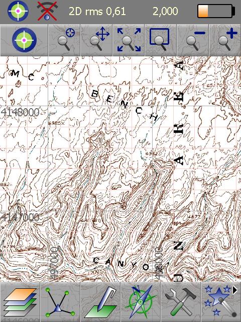
13 Penmap Home Screen After selecting or creating a new project Penmap will bring you to the Home Screen The Home Screen is the main screen in Penmap and gives you access to all functionality and applications. You can return to the Home Screen from all applications by clicking on the Home (Penmap) icon on the Status bar. Status bar Navigation bar Map area Functions and Application bar The Functions and Application bar can offer multiple pages. To access the second page simply slide the button bar from right to left. To return to the first page slide the button bar from left to right or click on the Home (Penmap) icon. Icons Status bar icons: NTRIP Connection Estimated 2D Accuracy Antenna height Battery Status Navigation bar icons: Menu Exit Zoom to Last Map Pan Zoom to Extents Zoom to Window Zoom Out Zoom In Functions and Application bar icons: Workspace Manager Instrument Setup Data Collection Navigation, Stakeout Settings Edit Query, Measure Export, Save Google Maps application Calculator application Penmap encore User Guide (rev. 1.2) for Penmap encore / encoret v7.2! 13
14 Data Collection application You can access the Data Collection application from the Home screen by clicking on the Data collection icon. To return to the Home screen, click on the Penmap icon on the top status bar. ifeature Codes Status bar Navigation buttons Add GIS form Map area Graphic element controls Data collection with Penmap is very intuitive: To collect data simply: 1. Select a feature code from the ifeature selector, and 2. Select a surveying method from the Surveying Methods bar The current, active feature is shown on a green button. Button controls ifeature: Tap - To select / change a feature or disable the feature coding Tap&Hold - To add a feature (maximum of 5 features on the PDA version) Graphic element controls: Tap - To change the default Graphic element Tap&Hold - Toggle between End and Close a line feature Navigation buttons: Tap - Zoom In/Out or Pan and Zoom to Extents Tap&Hold - Toggle between Zoom In/Out and Pan/Extents controls Methods bar: Tap - Select a Method, Trigger for GNSS / Total Station measurement Tap&Hold - Access to GNSS or Total Station controls Slide right to left - Access to second page of Methods Undo / Redo Surveying Methods To Undo your last action during data collection: Simply slide from right to left on the top status bar; To Redo: Slide from left to right. The PC version offers dedicated buttons for Undo/Redo left and right of the Home (Penmap) icon. Undo Redo Penmap encore User Guide (rev. 1.2) for Penmap encore / encoret v7.2! 14


15 Icons Overview Surveying Methods GNSS with SV count Total Station Snap to Node Free Node Bearing & Distance Visual Bilateration Visual Chain & Offset Key-in Coordinates Sketch Construction Lines Graphic Elements Graphic Point Graphic Text Symbol 1 anchor node Symbol 2 anchor nodes Polyline Bezier Curve 3 Nodes Arc Circle: Center and Radius Circle: 2 Nodes Circle: 3 Nodes END: Line feature CLOSE: Line feature Add GIS record Zoom and Navigation controls Zoom Out Zoom In Map Pan Zoom to Extents Onscreen Keyboards PDA: You can either use the keyboard provided by Windows Mobile or use the Penmap keyboard. For all numeric fields Penmap will provide its integrated large button keypad. To access the Penmap alphanumeric keypad simply tap&hold on any text entry box. TabletPC: To access the Penmap alphanumeric keypad simply double tap on any text entry box. Penmap encore User Guide (rev. 1.2) for Penmap encore / encoret v7.2! 15
16 Surveying Methods bar The Penmap Field Editing System has a comprehensive set of more than 10 main surveying method, including GNSS, Total Station, to generate nodes on a survey. Nodes generated by each Penmap Survey Method are identified in the Penmap map space by a specific blue symbol. Any method or combination of methods for generating nodes can create any graphics item. A variety of method routes can create the same graphics item. Different graphics items can be created from the same combination of nodes. Furthermore, the user has a wide range of editing functions and expansive features that can be activated simultaneously while a node is being generated and graphics item created. This is a fully integrated system. Types of nodes generated by Method Broadly speaking the nodes that are generated fall into two categories: 1. Nodes generated independently of other nodes The Free Node and Enter Data Method allows the user to create new nodes arbitrarily on the survey (although usually by referring to the base map or grid, or entering a coordinate). 2. Nodes generated with reference to other nodes All the other methods require that node positions are calculated by either using the coordinates of base nodes already laid down by the Free Node and Enter Data Method, or from the nodes that make up the base map of a survey, or in the case of Total Station nodes, by referring to a station setup. Note: In order to see the nodes which have been generated, check that the 'Show Survey Nodes' check box has been checked on Settings - Properties - Display/Map tab. Accessing the coordinates of nodes The coordinates and the used method to create a node can be reviewed by selecting: Query - ID Node and then tap on the node. Penmap encore User Guide (rev. 1.2) for Penmap encore / encoret v7.2! 16


17 GNSS method The GNSS Method option obtains coordinate data to create nodes in the survey utilizing a GPS device. Nodes can be accepted from single or multiple observations, from the mean of a number of observations, and at prescribed time intervals. Before collecting data, it is necessary to setup the GPS device and other parameters associated with collecting GPS measurements, like a coordinate system. Tab&Hold on the GNSS icon to access the GNSS controls. Click on the GNSS icon to start the GNSS Method. If no GPS device was setup, Penmap will try to detect the receiver type automatically or brings you to the GPS receiver setup for manual selection of receiver and communication parameters. When a GPS receiver is connected to Penmap the GNSS icon will show the number of used satellites as a badge. A red colored badge warns that not enough satellites are used to calculate a position. A green color means that Penmap can calculate a position and will show your current position as a color-coded cursor on the map. GNSS Status information Penmap makes quality control easy and intuitive. All important status information, including number of satellites, accuracy level and battery status are visible at all times. Additional information is always accessible, and you are not overloaded with unnecessary detail. Penmap encore s unique, color-coded GPS cursor makes it simple to produce data within your required accuracy level. Penmap also stores complete surveying meta data for reporting and quality control. Estimated accuracy Number of used satellites GPS Measurement - Create a GPS node Antenna height Click to enter/change it. Color-coded GPS position cursor: Outside the quality limits. Measurement is not possible. Warning limit. You have to confirm a warning message before able to log this position. Within the defined quality limit. Measurement will start immediately after clicking the GNSS method button. Click on the GNSS method button to start a GPS measurement. Depending on the selected Collection mode, a node will be created by a single epoch, by averaging over multiple epochs, or by using defined time intervals. Penmap encore User Guide (rev. 1.2) for Penmap encore / encoret v7.2! 17


18 GNSS Settings and Controls When you click the GNSS Method button the very first time, Penmap will automatically suggest a safe GNSS receiver setting. If you have installed Penmap on a Trimble Mapping receiver, Penmap will detect the correct receiver and will set the COM port automatically. To access the GPS Settings and Controls, Tap&Hold the GNSS Method button in the data collection application. To further access the GNSS settings, click on the Settings icon. GNSS Receiver Click on the GNSS Receiver button to select your connected GNSS receiver and communication parameters. Currently you can choose between Trimble Mapping receivers and any receiver using standard NMEA messages. If you run Penmap on a Trimble handheld GPS receiver, the correct receiver type and COM port will be detected automatically. Click the Test button to check the selected communication parameters. Penmap will display the receiver type and firmware version. If you want to use the NMEA interface you can decide between the standard Windows Mobile GPS interface (the operating system will set and control the communication parameters automatically in the background) or you can set the NMEA communication parameters manually. Coordinate system You need to select a coordinate system (transformation and projection) in order to get grid map coordinates (Northing, Easting, Elevation). Penmap includes 2 different transformation libraries: A Trimble library and a Penmap library. By default the Trimble library is selected. To change your default library: In the Home screen go to: Settings - Properties - Startup Tab - Transformation Tab. If you are unsure which system to use in your country, please contact your local Geodetic or Mapping agency. You can also contact Penmap support and we will try to assist you in the correct settings for your region. Penmap encore User Guide (rev. 1.2) for Penmap encore / encoret v7.2! 18

19 Quality Penmap makes Quality control of your data very easy and intuitive. Status information will show you the current GNSS status instantly: Number of used satellites - Displayed as a badge to the GNSS Method icon Estimated 2D accuracy - Displayed in meters at the top status bar Quality status (solution, accuracy) - Color coded GNSS position cursor You can easily customize the Quality status settings (color codes) by clicking on the Quality button in the GNSS Settings selector. Penmap distinguishes between 3 color codes: Red: Position will be displayed, but you can t log it. Amber: Logging a position is possible, but you need to confirm a warning message Green: You can log the current position instantly. You can select 2 parameters to control the color code settings: Required solution status: Uncorrected, DGPS, Float, Fixed Required 2D Accuracy in Meters You can choose between 5 pre-defined settings by using the slider bar. This will control the solution status options. In addition you can manually change the suggested 2D accuracy thresholds by clicking on the values. A numeric keypad will allow you to change the default settings. Your updated parameters are stored as your new Penmap configuration and are used every time you start Penmap. Collection mode Penmap supports 3 different collection modes for GNSS positions, independent from the selected feature: Single: Click on the GNSS Method button will log the current position Average: To increase accuracy and reliability of your logged GNSS position you can select a number of epochs (seconds). Penmap will store the averaged (mean) position. Continuous: For specific features it can be convenient to log positions automatically in a user defined time interval. Real-Time settings Here you can select the source for your real-time correction data. SBAS (a free satellite correction service) is set by default. You can define various real-time correction settings, called Services, and assign names to them. This makes it very easy to switch between different correction data streams (e.g when using NTRIP). Penmap encore User Guide (rev. 1.2) for Penmap encore / encoret v7.2! 19

20 SBAS Correction Services A Satellite Based Augmentation System (SBAS) is a system that supports widearea or regional augmentation through the use of additional satellite-broadcast messages. Such systems are commonly composed of multiple ground stations, located at accurately-surveyed points. The ground stations take measurements of one or more of the GNSS satellites, the satellite signals, or other environmental factors which may impact the signal received by the users. Using these measurements, information messages are created and sent to one or more satellites for broadcast to the end users. Most SBAS are free correction services. Depending on the receiver type, Penmap supports WAAS (North America), EGNOS (Europe) MSAS (Japan). SBAS correction services give approximately 2-5 meter horizontal accuracy. The map below shows the typical coverage areas of the different services. If you are outside these areas or require a higher position accuracy you can use a radio, beacon or NTRIP service to correct your position in real-time. Penmap encore User Guide (rev. 1.2) for Penmap encore / encoret v7.2! 20

: 1.")
21 Setting up your NTRIP correction service NTRIP is a convenient way to receive realtime correction data in the field using an internet connection. You will need a mobile phone or integrated modem in your GPS receiver and a subscription to a data plan. There are worldwide several free NTRIP services available or you can subscribe to a commercial service like Trimble VRS Now. Setup of your NTRIP service is very simple using Penmap s wizard (please ensure that you are connected to the internet via WiFi or modem): 1. Go to the Data collection application and Tap&Hold on the GNSS Method icon. 2. Click now the Settings button and select Real-time Corrections. 3. Now create a new Real-time correction service by clicking the New button. 4. Now enter a name for this service and click the Next button. Step 3 Step 4 5. The next setup page is receiver dependent. For Trimble Pathfinder/Mapping receivers click the Real-time tab and select Internet as the Source Type and SBAS as the Secondary Source. Step 6 Step 5 Step 5 6. Click now on the settings icons right of the Internet Source Type to configure your NTRIP source. 7. Please enter your NTRIP server and user account information into the fields provided, click the settings icon right of the source to request the source table and select the mount point for the data stream (Internet connection required). Penmap encore User Guide (rev. 1.2) for Penmap encore / encoret v7.2! 21


22 Request source table 8. Click OK to save your settings. 9. Ensure that your new service name is selected under Real-time Correction settings and accept it by clicking the green tick. NTRIP Client for RTK receivers Step 7 & 8 Step 9 Penmap contains an integrated, very easy to use NTRIP client to receive correction data from NTRIP casters around the world. This client is used when connected to RTK receivers, like the Trimble 5800 / R6 / R8 series. The Penmap NTRIP client contains a database of the most common NTRIP casters worldwide. You just need to select your country and Penmap will suggest available casters and connect to them. You will only need to enter your user account details (user name and password). Setup Follow the Steps from the previous section and add a new service. Add a new NTRIP caster by manual Select a NTRIP caster from the list Select NTRIP caster from list. Caster details will be displayed. Click on Select stream... to get available mountpoints (Internet connection required!). Select mountpoint (data stream). Penmap encore User Guide (rev. 1.2) for Penmap encore / encoret v7.2! 22

23 Get mountpoint details Enter User name and password. Click Accept to save the settings as a new Real-time correction service. Connect to a NTRIP correction service After setting up NTRIP as your Real-time correction service connecting and disconnecting to and from the service is a simple button click: Tap&Hold the GNSS Method button to access the GNSS Method Controls. Click on the Connect To icon to connect to the NTRIP caster. The connection icon in the top status bar will change to Connected. To disconnect simply click the Disconnect icon. Connect to NTRIP Disconnect from NTRIP Penmap encore User Guide (rev. 1.2) for Penmap encore / encoret v7.2! 23

 Click the Total Station icon to connect to the instrument.")
24 Total Station method The Total Station method allows the coordinates of target nodes on the site to be calculated using an Optical Total Station or any other device which can compute a bearing and distance. For the purposes of this method, the term Total Station includes specified binocular and monocular instruments with laser range finding such as the MDL LaserAce 3D. To use this method it is necessary to have: 1. Selected the correct instrument and communication parameters (Total Station Setup - Instrument Settings), and 2. Setup the instrument using one of the stationing procedures (Total Station Setup - Setup / Resection) Click the Total Station icon to connect to the instrument. If the instrument is connected, a little green tick at the icon will indicate the connection. An additional little toolbox icon gives you access to the Total Station controls. Click on this icon to open the toolbox The Total Station Controls toolbox The Main tab allows you to view and edit the target (prism / staff) height. The Offsets tab allows you to view and edit the target offset (left/right, in/ out) and to enter the prism constant or select a prism preset. The Options tab lets you to activate the reflectorless mode if supported by the instrument. Note: If connected to a Robotic Total Station, additional controls will be shown. Penmap encore User Guide (rev. 1.2) for Penmap encore / encoret v7.2! 24

25 Snap to Node method This method option rapidly collects nodes together to form graphics items selected from the Graphics Menu. It is not a method, which generates nodes; it is a method which snaps graphics items onto existing nodes. It is necessary to have at least one node laid down on the survey to begin. Alternatively, this method can be used as a type of edit utility to snap together nodes to form new graphics items after others have been 'undone' or 'erased'. Select this Method by clicking on the Snap to Node icon. This method stays active until another method is selected. To use this method it is only necessary to touch the node required to snap it. Usually the node will be snapped to another node to form a graphics item, but when the feature is a Graphic Point or Symbol the Snap Node method simply creates graphics points; it does not join them to anything. This is useful when recording the position of such items as traffic signs, telegraph poles or manhole covers. The Snap Node method is also a convenient method to create text adjacent to a number of nodes or graphics items. If the position of a node is recalculated the text will move with the snapped node. Free Node method Select this Method by clicking on the Free Node icon. This method stays active until another method is selected or the button is clicked again. To use this method it is only necessary to touch the desired position in the Penmap map space to create a free node. Penmap will calculate its coordinate value from the position of the pen and a small circle denoting a free node is displayed at that position on the survey. The Free Node method is also a convenient method to create text adjacent to a node or graphics item. If the position of other nodes is recalculated, text attached to free nodes will remain in the same position, as free nodes have been generated independently of other nodes. Note: The level is forced to be Zero. Penmap encore User Guide (rev. 1.2) for Penmap encore / encoret v7.2! 25

26 Visual Bearing & Distance method To use this method it is necessary to have one node in position on the survey, to know its distance (measured by tape measure or Laser rangefinder on the site) from the target node, and to determine North from a compass reading. From this data Penmap will be able to calculate the coordinates of the bearing and distance node. Procedure for Visual Bearing & Distance method Select the method by clicking on the Visual Bearing & Distance icon. The Method remains active until the Exit Method button is pressed. Select Method Exit Method Step1: Snap to the reference node. Step2: Enter the Azimuth (compass reading) and the vertical angle. Default vertical angle is 90 degrees (horizontal) and doesn t need to be entered. Step3: Enter the horizontal distance to the target. Step4: Penmap will show the result on the map. Click the Accept button to create the node or modify your entered data. Tip: You can create multiple Bearing & Distance nodes from a single reference node. Just change the azimuth angle or/and distance. Previous entered data stay in memory for faster node creation. Penmap encore User Guide (rev. 1.2) for Penmap encore / encoret v7.2! 26
. From this data, Penmap will be able to calculate the coordinates of the Bilateration node. You can use this method in 2 scenarios: 1.")
 and take measurements to the two reference nodes, e.g. corner of a building.")
27 Visual Bilateration method To use this method it is necessary to have two nodes in position in the survey and to know their distance from the target node (measured by tape measure or Laser rangefinder on the site). From this data, Penmap will be able to calculate the coordinates of the Bilateration node. You can use this method in 2 scenarios: 1. You are starting from one reference node and measure the distance to the target, then moving to the second reference node and measure this distance to the target. This is ideal for a single feature. 2. You can also stay at the target (e.g. a manhole, tree) and take measurements to the two reference nodes, e.g. corner of a building. Then move to the next target and take new distance measurements to the same reference nodes. This is a very fast process when you want to collect multiple features or a line feature with a Laser rangefinder to two known positions on the map (e.g. collected with the GNSS method before). Procedure for Visual Bilateration method Select the method by clicking on the Visual Bilateration icon. The Method remains active until the Exit Method button is pressed. Select Method Exit Method Step1: Snap to the two reference nodes. Step2: Measure and enter the horizontal distance from node 1 to the target. Step3: Measure and enter the horizontal distance from node 2 to the target. The node position will be displayed. Step4: Tap on the map to toggle between the 2 possible solutions. Click the Accept button to create the node. Penmap encore User Guide (rev. 1.2) for Penmap encore / encoret v7.2! 27


28 Data Entry method To use this method it is necessary to know the plane or WGS84 coordinates of the target position on the survey to lay down a node. The node generated is a free node. If you enter WGS84 coordinates in Latitude, Longitude and Altitude the transformation and projection parameters have to be defined in the GNSS settings. Select the method by clicking on the Data Entry icon. The Method remains active until the Exit Method button is pressed. Select Method Exit Method Your have 3 different options to enter your coordinates: 1.Enter plane/grid coordinates in Northing, Easting, Level 2.Enter WGS84 coordinates (Latitude, Longitude and Elevation) in Degrees, Minutes, Seconds, or 3.Enter WGS84 coordinates (Latitude, Longitude and Elevation) in Decimal degrees. Click the! " button to separate degrees, minutes, seconds. Click the N or E button to toggle between N/S and E/W. Penmap encore User Guide (rev. 1.2) for Penmap encore / encoret v7.2! 28
. From this data Penmap will be able to calculate the coordinates of the chain and offset node.")
29 Visual Chain & Offset method To use this method it is necessary to have two nodes in position on the survey and to know two distances - the chain and the offset measurements (measured by tape measure or Laser rangefinder on the site). From this data Penmap will be able to calculate the coordinates of the chain and offset node. The chain value measurement is the distance from the first base node, along a line that joins the two base nodes and possibly beyond it, to a point where the normal to that line from the target node meets it. By entering a negative distance value you can use this method also as the Extend method, which was available in earlier Penmap versions. The offset value measurement is the distance along the normal from the target node to the end of the 'chain'. Positive values are right of the chain line, negative values left of it. Procedure for Visual Bilateration method Select the method by clicking on the Visual Chain & Offset icon. The Method remains active until the Exit Method button is pressed. Select Method Exit Method Step1: Snap to the two reference nodes. Step2: Measure and enter the horizontal chain distance from node 1. Step3: Measure and enter the horizontal offset distance to the target. The node position will be displayed. Step4: Tap on the map to toggle between the 2 possible solutions. Click the Accept button to create the node. Penmap encore User Guide (rev. 1.2) for Penmap encore / encoret v7.2! 29


30 Freehand/Sketch method This Method allows the user to sketch with the pen onto the screen. It contains algorithms for automated shape recognition and can only be used in conjunction with line features. Penmap will automatically set the Graphic element to Bezier curve. All Sketch nodes are treated as free nodes. Penmap calculates its coordinate value from the position of the pen and a small circle denoting a Free node is displayed at that position on the survey. This method is the digital version of freehand sketching on paper. It is ideal for all highly-detailed features which are impossible or impractical to survey with traditional surveying methods. Use this method in conjunction with the GNSS or Total Station method which provide a very accurate framework for your freehand sketching. Select the Freehand button. Draw a sketch on the survey with the pen by drawing on the screen with the pen. Draw a sketch with the mouse by holding down the left button of the mouse and moving the mouse to perform the sketch which is displayed on the survey. Lifting the pen off the screen or lifting a finger off the mouse button ends the sketch and a series of free nodes with connecting line elements is displayed on the survey. Wait for the start tone, then start sketching. After finishing the freehand drawing click the End Feature button to end this element. Tap&Hold the End Feature button to toggle to Close Feature and then close the graphic element. After ending the feature, Penmap will draw a smooth curve. You can now also add a GIS record to this element. Penmap encore User Guide (rev. 1.2) for Penmap encore / encoret v7.2! 30

31 Visual Construction method The Construction Method enables the user to create construction objects from which nodes are generated at the intersections of these objects. Existing nodes and graphics on the survey are used to create the construction objects. Each button on this dialog creates a different type of construction object. In some cases when creating construction lines, the user is presented with a choice of position for the object. Tap on the map to change the Sense of Construction and to view the alternatives before selecting one. If two or more construction lines are intersecting a new Construction node will be created. Close this method when all required nodes have been created on the map. You can now use the Snap to Node method to assign features to these nodes. Create a Construction Line Parallel to another Line Use this method to create a construction line parallel to an existing line defined by two nodes. You can either define the offset by entering a distance or by selecting a third (through) node. When using an entered distance you can tap on the map to toggle between the two possible solutions left and right of the reference line. Snap to the two reference nodes to define the construction line. Enter a distance offset, then click Accept to create the construction line - or... Select a through node, then click Accept to create the construction line. Penmap encore User Guide (rev. 1.2) for Penmap encore / encoret v7.2! 31
32 Create a Construction Line at Right Angles to another Line Use this method to create a construction line perpendicular to an existing line defined by two nodes. You can define an offset either by entering a distance from node 1, by selecting a third (through) node or by using exactly the middle between node 1 and 2. When using an entered distance you can tap on the map to toggle between the distance referenced to node 1 or 2. Snap to the two reference nodes to define the construction line. Enter an offset distance. Tap on the map to toggle between different solutions. Define the offset by selecting a trough node. Tap&Hold on this button to toggle between Enter offset and Use Middle point. Create a Construction Line which Intercepts another Line at an oblique Angle Use this method to create a construction line in a specific angle to an existing line defined by two nodes. Enter in the Intercept (Offset) value from the start or end node on the selected line. This is the point where the construction line will intercept the selected line or you can use the middle point. Enter in a value for the angle of the construction line from the selected line. Select the Intercept button. Penmap encore User Guide (rev. 1.2) for Penmap encore / encoret v7.2! 32
33 Snap to the two reference nodes to define the construction line. Click here to define an offset from the reference node and enter an angle (90 degrees is perpendicular to the reference line). Tap on the map to toggle between 4 possible solutions (offset reference and angle orientation). Tap&Hold on this button to toggle between Enter offset and Use Middle point. Create a Construction Line that has a specific Bearing Use this method to define a construction line by its azimuth angle from a reference node. This method is useful if you want to determine a feature position by two compass readings to two reference node (resection). Snap to the reference node to define the construction line. Enter the azimuth value to the reference node. Penmap encore User Guide (rev. 1.2) for Penmap encore / encoret v7.2! 33
34 Create Construction Object: Circle by Radius With this method you can create a construction line as a circle. You can define the circle by either: The center point plus radius, 2 nodes on the circle plus radius or by 3 nodes on the circle. Create the final Construction Node(s) Define the first construction object, then click Accept. The line turns Green. Define the second construction object, shown in red here. After accepting the second construction line, Penmap will create the construction nodes at all intersection points. You can add additional construction objects. After closing the Construction method the construction lines will be removed, leaving only the new construction nodes. Use the Snap to Node method to attach graphic elements to them. Penmap encore User Guide (rev. 1.2) for Penmap encore / encoret v7.2! 34


35 Visual Stakeout / Navigation application Penmap offers a unique and very intuitive stakeout application. The combination of the gorgeous map display and optimized workflows make stakeout or navigating to features very fast, easy and more enjoyable. You can stakeout from imported point lists or straight from rich CAD drawings without the need to extract single points first. To access the Stakeout/Navigation application click on the Navigation button of the Home screen. If you are connected to a GNSS receiver the new Visual Stakeout application will be launched. From the main Navigation screen you have access to the two options: Visual Stakeout to a Node/Point feature, and Visual Stakeout to a Reference line. If you are connected to a Total Station and have a valid instrument setup Penmap will launch the legacy Stakeout toolbox for the moment. To exit the Visual Stakeout application, simply click on the Penmap icon in the top status bar to return to the Penmap Home screen. Visual Stakeout to Node Penmap s Visual Stakeout provides an intuitive, seamless workflow from feature selection through coarse and fine navigation to taking the final verification measurement. The following pictures walk you through the automated workflow: 1.Select Feature To stakeout a single node, click on the Node icon left on the bottom bar and then select the node from the map. You can access nodes from your current survey or from a vector background map. Use the map navigation buttons on the top to navigate the map. The middle GNSS button gives you the same functionality as the GNSS Method button in the data collection application. Tap&Hold gives you access to the GNSS controls, the badge indicated the number of used satellites. The selected node will be highlighted in red. Penmap encore User Guide (rev. 1.2) for Penmap encore / encoret v7.2! 35

 Penmap will switch into the Fine")

. This is the defined horizontal stakeout error limit.")

36 2.Coarse Navigation Immediately after selecting the feature Penmap will enter into the coarse navigation mode. It will adjust the zoom to show both: The target node and your current GPS position on the map. Both are connected by a thin blue line to indicate the direction to walk. The bottom bar shows two icons to tell you the azimuth angle and the distance to the target. Penmap will automatically adjust the zoom to give you the best view of the map. 3.Fine Navigation After reaching the coarse/fine navigation threshold (default value is 20m, but you can change this setting under Settings - Properties - Stakeout tab) Penmap will switch into the Fine Navigation mode: The target node is now in the center of the map area and blue circles indicate the distance to the target. The bottom bar icons have changed and show now the remaining distance to the target in the North/South and East/West component. In the upper part of the map screen the vertical displacement bar is visible now to show you the cut/fill value and a visual indicator. Also here Penmap automatically adjusts the map zoom. When you are getting closer to the target a green circle gets visible (at 0.25m in this example). This is the defined horizontal stakeout error limit. You can set an error limit for the maximum horizontal and vertical displacement under Settings - Properties - Stakeout tab. (default value is 4cm, a value of 0 means that this error limit will be ignored. Also for target node elevations of 0m the vertical displacement will be ignored by default (can be changed under Settings - Properties). When you are within the defined stakeout error limits the inner green circle gets filled in light green and the vertical displacement indicator is shown in light green as well. 4.Verification Measurement You can now take a verification measurement by clicking on the GNSS icon of the lower icon bar. You can change between single and averaged observations by changing the Collection mode (same as in data collection). A confirmation message informs you about the final displacements and the fulfillment of the error limits. (you can disable this message under Settings - Properties - Stakeout tab) Penmap will now return to the main Navigation screen. All verified (staked out) nodes are highlighted in Green. Penmap encore User Guide (rev. 1.2) for Penmap encore / encoret v7.2! 36


37 Visual Stakeout to Reference line Penmap s Visual Stakeout to Reference line provides an intuitive and seamless workflow from reference line selection, definition of parallel, angled and station offsets through coarse and fine navigation to taking the final verification measurement. The following pictures walk you through the automated workflow: 1. Select Reference line Use the two buttons to the left and snap to two nodes in your map to define the reference line. Node 1 is always the start node, node 2 defines the orientation of the line. Tap&Hold on any button of the lower bar to toggle between parallel offset or angled line definition. 2. Define a Line Offset If required you can now define a horizontal line offset by entering an offset distance or by selecting a third node. 3. Define a Station Offset If required you can now define a station offset for node 1. A positive value will move node 1 towards node 2, a negative value to the opposite direction. To start the Navigation process click on the Accept button. 4. Navigation and Verification The navigation process is identical with the Stakeout to Node workflow. Penmap will display the Chain and Offset values and in Fine Navigation mode also the vertical displacement in reference to node 1. Penmap will adjust the zoom automatically and displays the error limits. After the verification measurement you can continue with the current line definition or return to the line definition step. Penmap encore User Guide (rev. 1.2) for Penmap encore / encoret v7.2! 37
 This is the data you are collecting or you have imported into Penmap. 2.")


38 Workspace Manager The Penmap Workspace Manager is the main place to manage your data sources. In general Penmap handles 3 major categories of data sources: 1. Survey data (foreground data) This is the data you are collecting or you have imported into Penmap. 2. Vector background maps These are vector data managed in an optimized way for faster speed and to handle huge data sets even on PDA devices. You still have full access to nodes, graphics and GIS records, but these maps are protected from deletion and are not part of the export function. 3. Raster background maps Penmap uses Raster background maps in an optimized way with a special tiling mechanism. This enables Penmap to process huge raster maps even on PDA devices with RAM limitations. Import files Files you are importing into Penmap are stored as Survey data in the foreground and become part of your collected data. Penmap supports following formats: UNV (Universal Format/Map500-open). This format is Penmap propriety and contains all data of the Penmap database. This format is often used by 3rd party developers to provide a comprehensive data exchange between Penmap and other CAD or GIS packages. AutoCAD DXF. This format is ideal to import rich graphic information, drawings and symbol libraries. CSV (Comma separated values). This format is ideal to import point data with point numbers, coordinates and codes. T.O.C. (Table of Contents) Penmap s Table of Contents is the main place to manage background data as vector and raster maps. From here you can load vector and raster background maps, control their layers and manage their styles (e.g. line colors and area fillings). Change the drawing order. Add or remove background maps. Add ESRI Shape files. Add ESRI Map file (.apm) Add Raster maps. Add Vector maps. Penmap encore User Guide (rev. 1.2) for Penmap encore / encoret v7.2! 38


39 Add Raster background maps Penmap supports geo-referenced raster maps in TIFF, JPG and PNG format together with a corresponding world-file. Before you can load any raster map into Penmap you have to pre-process them in the MapTiler program which is part of the Penmap office or TabletPC installation and doesn t require a license key. MapTiler optimizes a single or multiple raster files for use on a PDA and TabletPC and creates a *.pmi Mosaic file. You will find more details about MapTiler in the last chapter. To load a Penmap Mosaic file, select Add Rastermap from the T.O.C. toolbox. To disable a specific Mosaic file, just uncheck the individual selection box. Note: If you have non-georeferenced raster maps (without a world-file), we recommend the free WGEO Basic software from: to create a world-file using controls points. Add Vector background maps Vector background maps are very useful as a reference for your survey. You can use their information for control, backsight, calibration or stakeout points. All information are protected from accidental deletion or unintended modification. To use vector background maps you have to process your DXF or Shape files in Base Maps application first. Now you can select you map group by click Add Base map. The T.O.C. allows you to modify the style and color of line and area elements in your base maps and to control the visibility of its layers or themes. You can use the top right arrow up and down buttons to change the order of drawing layers (important if you have area fillings). Penmap encore User Guide (rev. 1.2) for Penmap encore / encoret v7.2! 39


 of Shape files or other Vector background data, please use the T.O.C.")

40 Base Maps The Base Maps functions allows you to create Vector background maps in the optimized Penmap format *.ibf. You can select multiple DXF and ESRI Shape files and convert them into this format. Important: The creation of Vector background maps on a PDA is limited to a maximum of 2MB of DXF or SHP data due to memory limitation of most PDAs. If you want to process larger or more files please use the Penmap office software. You can then copy across the processed Vector background maps to your PDA device. Vector background maps should be placed into the: Penmap encore\backgroundmaps\ folder. Layer Toolbox The layer toolbox manages layer information of all Survey data (foreground). To control layers (themes) of Shape files or other Vector background data, please use the T.O.C. Linestyle tab Text tab Visibility tab Library tab Here you can create new layers and define the appearance of the graphics: colors, line style and properties. To create new linestyles edit the file: linestyles.txt in: Penmap encore \stock\fixed\ Here you can define the properties of graphic text at the specific layer. Here you can enable or disable the display of all graphics on the selected layers. After editing your layers you can save them into an existing or new library. You can then select this layer library in the template definition. Layer libraries are stored under: Penmap encore\stock\ Penmap encore User Guide (rev. 1.2) for Penmap encore / encoret v7.2! 40
41 Total Station Setup Instrument Settings Select here your optical Total Station or Laser rangefinder and the communication parameters (COM port, Bluetooth etc.). You can download a list of the all supported instruments of the most recent version from Instrument Setup / Resection This button gives you access to the Total Station setup. Penmap supports all major methods of setting up a Total Station on a known point with multiple backsight observations or sophisticated Resection algorithms to use multiple backsights to calculate your Total Station s current position, orientation and network scale factor. Note: You have to perform an instrument setup first before Penmap accepts data collection or stakeout with the Total Station method. For more workflow details we recommend the video tutorials on Penmap encore User Guide (rev. 1.2) for Penmap encore / encoret v7.2! 41


.")


42 Penmap Settings Properties Properties is the main place for all Penmap settings for display, license, settings for DTM and Stakeout. language version etc. The Display settings control if nodes and background map information should be shown and controls the appearance of the map grid. Under Startup you can select the transformation library (required for GPS method). If you have difficulties with the current configuration it can be useful to reset Penmap to factory defaults. The Key tab provides information about your license. The DTM tab lets you generate a DTM from your survey nodes. The Export tab allows you to configure the CSV and DXF export. Under Advanced you can modify the Autobackup function. Select Graphics mode to Shapes if you want to force Penmap to create Shape files automatically after adding a GIS record. Penmap encore User Guide (rev. 1.2) for Penmap encore / encoret v7.2! 42


43 Tolerances Use Tolerances for Total Station method and Resection specific settings and to select your distance and angular units. Symbols Toolbox The Symbol toolbox controls the library of graphical (CAD) symbols (e.g. AutoCAD blocks). If you import DXF files including block information, these symbols will be automatically added to the current symbol library. Here you can define or modify the anchor nodes, change the default symbol size and save the symbols into a new library file. Review symbols and define if you want to use one or two anchor nodes. Define the position of the symbol s anchor nodes. Save symbols into a library file. Define or modify the default symbol dimensions. Customizer The Penmap encore Customizer is an easy way to configure the available surveying methods in the data collection application. You can add, remove and change the order of the available methods in the lower surveying methods bar. Note: The Customizer is not available in Penmap encoret (Tablet PC version). Penmap encore User Guide (rev. 1.2) for Penmap encore / encoret v7.2! 43
44 ifeature Editor The ifeature Editor allows you to edit or create features / feature codes for your data collection in your current selected feature file (defined by the loaded template). If you want to start with a new feature file, we recommend to load a template with the Generic feature file (codes_generic.txt). Penmap encore User Guide (rev. 1.2) for Penmap encore / encoret v7.2! 44


45 Edit Functions Delete Item With this function you can delete nodes, graphics and GIS objects / shapes. Please note that if you delete nodes, also all attached graphic elements and GIS objects will be removed from the map. If you delete only graphic elements, the surveying nodes remain in the map and can be used for other graphics and features to be attached to them. You can select single nodes, graphics, shapes or you can mark all elements in a rectangle to be deleted. Delete Shapes Delete Graphic elements Delete Nodes Adjust Text Select the text you want to adjust. the text will be shown in a small red adjustment box. Move text Rotate text Scale text Adjust Symbol Penmap provides an adjustment toolbox which allows you to move, rotate and scale your graphic symbol. First click the Select button and then snap to the symbol. Penmap will show the selected symbol in a small red adjustment box. Use then the control buttons to make the desired modifications. To close the toolbox, click on the small cross on the top right. Penmap encore User Guide (rev. 1.2) for Penmap encore / encoret v7.2! 45


46 Add GIS You can also add GIS attributes to an existing graphic element in your survey. 1. Select feature/object class Click the Add GIS button and then select the feature or object class from the drop down list. To accept, click the green tick icon. 2. Review or Edit attributes Use now all the tabs to review or fill-in your attribute data. 3. Add Graphic element link Go now to the Parts tab and click on the Add button. You can now snap to a graphic feature in your survey. You can add multiple elements. Note: Penmap allows also creating of Donut objects. Edit / Review a GIS record To edit or review GIS records in your survey, go to the Penmap Home screen and tap&hold on the corresponding little black square icon. This will open the GIS entry form for reviewing or editing the attribute data. Penmap encore User Guide (rev. 1.2) for Penmap encore / encoret v7.2! 46


47 Corridor This function replaces a polyline with a corridor by entering left and right horizontal and vertical offsets. Add Offset This function adds a parallel polyline to an existing line feature by a defined offset. Select the start and end node of the line feature. Split Distance Enter the horizontal offset value and click the Create and Accept button. Select the layer for the new line feature. Penmap allows you to split a line feature or any distance between 2 nodes into sections of either defined horizontal or slope intervals or into a defined number of sections. Penmap encore User Guide (rev. 1.2) for Penmap encore / encoret v7.2! 47


48 Query Data ID Node This function returns details about the selected node, like coordinates, date when collected, which method was used to create this node and other method specific raw observation data. Click the icon and then select a node from the main map area. A toolbox will show you the details and allows you to examine additional nodes. ID Graphic This function returns details about the selected graphic element, like graphics type and layer. Click the icon and then select a graphic element from the main map area. A toolbox will show you the details and allows you to examine additional elements. ID Measure This function allows you to perform following instant measurements on the map: Distance between 2 nodes in the map Distance between a node and a graphic element Angle between 3 nodes in the map Click the icon and Penmap will open a toolbox from where you can select the node (s) and graphic elements. Start node Shape file graphic Graphic element Second node Results Penmap encore User Guide (rev. 1.2) for Penmap encore / encoret v7.2! 48
49 Export Export UNV The Universal Format (UNV) is a Penmap propriety format for exchange of the complete Penmap database. This format was introduced with Penmap v5 and is used for a variety of specialized and local data exchange formats, e.g. Smallworld GIS. The format is ASCII and a documentation is available on request. Click on the icon and select a file name and location. Export DXF DXF is the widely used format (developed by Autodesk) to exchange all graphic information. This is the ideal format to exchange your drawings with AutoCAD, MicroStation and other CAD systems. Click on the icon and select a file name and location. Note: You can define specific DXF export parameters and settings from Settings - Properties - Export Tab (DXF and DXF+). Export CSV The CSV format is ideal to export your measured point/node database. Values are comma separated and contain point number, coordinates, and specific node data, e.g. date. Click on the icon and select a file name and location. Note: You can define specific CSV export parameters and settings from Settings - Properties - Export Tab (Node database). ESRI Shape files Shape files is the common exchange format for exchange of rich GIS data between Penmap and ESRI products (e.g. ArcGIS), but can also be used for most other GIS systems. When in Shape File mode Penmap works in native ESRI format and automatically creates the required Shape files. Feature editing is also done directly on the loaded Shape files. So no export or data conversion is required. You will find the created Shape files in a folder under My Documents with your current project/job name. Penmap encore User Guide (rev. 1.2) for Penmap encore / encoret v7.2! 49
50 Application links Penmap encore supports direct access to useful external applications straight from the Penmap Home screen. Please ensure that these applications are installed on your device to function properly. Google Maps Application A click on the Google maps application icon will launch Google Maps Mobile (on Windows Mobile devices) or the Google Earth application (on Windows TabletPC). You can use these applications for route guidance, finding the nearest POI (e.g. petrol stations) or check the current traffic status (where supported by Google). Calculator A click on the calculator icon will launch the native calculator application on Windows Mobile or Windows XP/Vista/Windows 7. These programs are part of the operating system and should be already installed on your device. Penmap encore User Guide (rev. 1.2) for Penmap encore / encoret v7.2! 50
51 Configuration and Customization Penmap offers the unique ifeature system to select the feature you want to collect. A Feature is a real-world object (e.g. a tree, a road curb) you want to survey and map. There are different terms in the Surveying and GIS community for basically the same thing: A surveyor will call it Code or Feature Code (therefor very often used the term code list or coding system ), a CAD professional uses Layers and Symbols to distinguish real-world objects, and a GIS administrator would call it Objects, Object classes, or Themes. Penmap supports all these definitions under the single term Feature. The Penmap ifeature system allows you to select the real-world object (Feature) you want to collect and automatically sets: Template The correct graphic element (point, symbol, polyline, arc, text, circle...) The correct style and color (line-, point-, symbol-style, line color) The correct attribute table (GIS record) if you want to attach additional information to the surveyed feature. All of these settings are controlled by the Template you select or define when starting a new project. A Template is a defined set of: Layer library file Symbol library file GIS data model file, and ifeature or Coding file This chapter explains how to create and setup these 4 files. We recommend to follow these steps: Layer 1. Create a Layer library file 2. Define a Symbol library or customize Point styles 3. Create a GIS attribute forms (GIS data model) 4. Create your ifeature library Penmap Layers control the line style, color, and text appearance of your graphic features in the map. In addition you can also use the Layer controls to enable/ disable the display of features in the map. Layers are stored in text files with the *.lay extension and are located at: \Penmap encore\stock. Use the Penmap Layer toolbox of the Workspace manager to add and customize your Layer settings. If you want to remove layers from a layer file, you can do this directly in the *.lay file by removing the specific line. We recommend to watch the video tutorial How to create and customize Layers on Penmap s support website. To create a new Layer file we recommend to start with the Generic template and the layer_generic library. Penmap encore User Guide (rev. 1.2) for Penmap encore / encoret v7.2! 51
52 Symbols Graphic symbols are organized in symbol libraries. Penmap symbol libraries have the *.sdn extension and are stored in the folder: \Penmap encore\stock\. To create your own symbol library please follow these steps: 1. Start Penmap with a new template and select as the library file: symbol_empty 2. Import a DXF file containing your graphic symbols (blocks). They will be automatically imported into the current selected symbol library. 3. Go to: Settings - Symbols to review the imported symbols and change the anchor points if necessary. 4. Use the Library tab to save the symbol library as e new library file. 5. Next time you start a project, create a template with your new symbol library file. Note: Penmap also allows to use Bitmap symbols (typical for an ESRI ArcGIS environment). Such symbols are called: Graphic Points in Penmap and are defined in the pointstyles.txt file, found at: \Penmap encore\stock\fixed\. Necessary bitmaps have to be placed into the folder:\penmap encore\stock\bitmaps\. The pointstyles.txt file contains also a comprehensive list of unscalable Graphic Point styles, like crosses, circles, squares and others. You can also add or customize such graphic points by reading the instructions in the file header. GIS Definition Penmap allows you to define and customize your own GIS data model (tables, GIS forms) or to import them directly from your ESRI or Smallworld GIS system. The GIS Definition is done in the Database Editor which is part of the Penmap office or Penmap encoret installation. You can download these programs from Penmap s support website. No license is required to run the Database Editor. GIS Definition files (*.xsd) are stored in the folder: \Penmap encore\gisschemas\. To customize your GIS definition, run the Database Editor (DBedit.exe) from the Penmap program group. The Database Editor supports 4 ways to define or customize your GIS data model: 1. From New (Create a new GIS data model) 2. From an existing Database (you can use the example *.xsd files which come with the Penmap installation, or other XML files) 3. From a *.dbf File (which are part of an ESRI shape files) 4. From *.apl or *.apm Files (from ESRI ArcPad or ArcGIS) Penmap encore User Guide (rev. 1.2) for Penmap encore / encoret v7.2! 52

 and assign a unique ID character to this table.")

 and define the default value and field details (compulsory, read only).")
53 From New - Create a new GIS Data Model 1. Start the Database Editor (DBedit.exe) program 2. Define Tables / Object classes by clicking the Add Table button. Enter a Table/ Object class name, select the GIS type (Symbol, Linear Group, Area group...) and assign a unique ID character to this table. This character will be used by Penmap in the little black GIS edit box in the map view of the Penmap Home screen. 3. Add attribute fields to the table by clicking on Add Field. Enter a database field name, select a Field type (Text, Integer, Date/Time, Photo, Sketch, a Measurement method or others) and define the default value and field details (compulsory, read only). 4. Enter Drop down list items if required and edit/adjust the page properties. Penmap encore User Guide (rev. 1.2) for Penmap encore / encoret v7.2! 53
 from the top main menu and click then the Quick Preview button. 6. Save as XSD file into the folder \Penmap encore \GISschemas\ 7.")
54 5. If you are designing the forms for the PDA platform we recommend to use the Quick Preview feature to check the appearance on the desired PDA screen resolution. Select first the screen resolution (screen height) from the top main menu and click then the Quick Preview button. 6. Save as XSD file into the folder \Penmap encore \GISschemas\ 7. For PDA: Copy the *.xsd file to \Penmap encore \GISschemas\ on the PDA From a Database 1. Export data model from a database in XML or XSD format 2. Select: File - Open, Browse to file and open it 3. Edit Table to add GIS types. Note: Name will be used for a label if the label field is blank. 4. Save as XSD file into the folder \Penmap encore\gisschemas\ 5. For PDA: Copy the *.xsd file to \Penmap encore\gisschemas\ on the PDA Create from an ESRI *.dbf File 1. Make sure all *.dbf and *.shp files are in the same folder 2. Select: File - Create From.DBF file and select all.dbf files required 3. Setup pages and labels as required. Note: Don t change types or field names! 4. Save as XSD file into the folder \Penmap encore\gisschemas\ 5. For PDA: Copy the *.xsd file to \Penmap encore\gisschemas\ on the PDA Create from ESRI *.apl or *.apm Files 1. Make sure all.apl, *.dbf and *.shp files are in the same folder 2. Select: File - Create From.APL /.APM file 3. Select all *.apl or one *.apm file required 4. Edit pages and labels as required. Note: Don t change types or field names! 5. Save as XSD file into the folder \Penmap encore\gisschemas\ 6. For PDA: Copy the *.xsd file to \Penmap encore\gisschemas\ on the PDA Penmap encore User Guide (rev. 1.2) for Penmap encore / encoret v7.2! 54

55 ifeature ifeature is a revolutionary fast way to organize and access your data collection features. In surveying terms this is often called feature coding or using a code list. But Penmap s unique ifeature goes beyond traditional feature coding. A feature in Penmap s ifeature file controls following information: Feature name - The name you find this feature in your list Topic / Page name - You can organize all features in separate pages, e.g. Topography, Utilities, Street Furniture... for quick access Layer - Places the feature on the defined layer and controls style and color Default Graphic element - Uses the defined Graphic element as a default, e.g. Symbol, Polyline, Circle, Text... Feature type: Point, Line, Area - Controls the feature end/close button GIS record - Will link the defined GIS record/form to this feature Symbol name and size - Defines Symbol name from the library, size, and orientation The ifeature configuration file is a simple text file, located in the: \Penmap encore\coding\ folder. You can use the 2 sample files to modify or adjust them to your specific needs. Penmap can handle unlimited ifeature file definitions. The currently used ifeature file for data collection is defined in the Penmap Template. Important: Please ensure that your ifeature file is compatible and matches the selected Layer file, Symbol library, and GIS definition file. Customize Methods Penmap allows you to customize the Method buttons of the data collection application. You can re-order or remove buttons from the lower button bar. From the Home screen go to Settings - Custom to access the Customizer application. Click on an icon in the upper part to add this Method to the button bar. Click on an icon in the lower button bar to remove it from the definition. You will need to restart Penmap so that your changes become effective. Penmap encore User Guide (rev. 1.2) for Penmap encore / encoret v7.2! 55
Penmap SURVEYING FOR EVERYONE. Getting Started Guide For STONEX S7
 Penmap SURVEYING FOR EVERYONE. Getting Started Guide For STONEX S7 Preface i Foreword Thank you for purchasing Penmap Mobile Data Collection software. Penmap is a unique and powerful Mobile Data Collection
QUICK START GUIDE. SOLO Forest
 QUICK START GUIDE SOLO Forest Software Installation 1. For PC installation, run the.msi file. 2. For Mobile device installation, copy the.cab file onto the device 3. Run the.cab file Starting the Program
User s guide December 2011
 User s guide User s guide December 2011 WARNINGS In writing this manual every care has been taken to offer the most updated, correct and clear information possible; however unwanted errors are always
Topcon GRS-1 1 Receiver Field Preparation
 Topcon GRS-1 1 Receiver Field Preparation What do you need to know to get started with your Topcon GRS-1? Topcon GRS-1 Receiver - Field Preparation Some Common Questions Which TopSURV modules do I buy?
TECHNICAL NOTES TRIMBLE SURVEY CONTROLLER SOFTWARE
 TRIMBLE SURVEY CONTROLLER SOFTWARE TECHNICAL NOTES The Trimble Survey Controller software is the data collection solution that will make your survey work faster, easier, and more productive than ever before.
Getting started guide
 GEOGIS Getting started guide Version 14.097 Revision C October 2015 STONEX Srl Via Cimabue 39 20851 -Lissone (MB) Italy Phone +390392783008 ; +390392785575 Fax+390392789576 www.stonexpositioning.com Contents
Release Notes SPECTRA PRECISION SURVEY OFFICE. Version
 Release Notes SPECTRA PRECISION SURVEY OFFICE Version 3.90.1 Corporate office: Spectra Precision 10368 Westmoor Drive Westminster, CO 80021 USA www.spectraprecision.com Copyright and trademarks: 2005-2017,
Evidence Recorder Release Notes
 Evidence Recorder 6.0.0 Release Notes Released on: October 5, 2009 Licensing Changes This release has had one big change and that is a new licensing system that gives us more flexibility to add different
Trimble Survey Controller. Release Notes
 Trimble Survey Controller Release Notes Version 10.5 Revision A September 2002 Corporate Office Trimble Navigation Limited Engineering and Construction Division 5475 Kellenburger Road Dayton, Ohio 45424-1099
StickFont Editor v1.01 User Manual. Copyright 2012 NCPlot Software LLC
 StickFont Editor v1.01 User Manual Copyright 2012 NCPlot Software LLC StickFont Editor Manual Table of Contents Welcome... 1 Registering StickFont Editor... 3 Getting Started... 5 Getting Started...
USER GUIDE. Trimble Positions software suite: Trimble Positions Mobile extension. Introduction. Transferring data between the field and the office
 USER GUIDE Trimble Positions software suite: Trimble Positions Mobile extension Introduction Transferring data between the field and the office How the extension works Finding additional information Appendix
User manual. TopoL Mobile 3.0. TopoL Software, s.r.o.
 User manual TopoL Mobile 3.0 TopoL Software, s.r.o. 2005-2012 TopoL Software, s.r.o. All rights reserved. TopoL is registered trade mark of TopoL Software, s.r.o. Obsah Content BASICS... 5 INSTALLATION...
Technical Note. 12 August 2009 PocketDTM Utility Surveys Brief Outline. Atlas Computers Ltd
 Technical Note 12 August 2009 PocketDTM Utility Surveys Brief Outline Atlas Computers Ltd 15 Moyville Lawns Taylors Lane Rathfarnham Dublin 16 Republic of Ireland Ph: +353(0) 1 4958714/5/6 Fax: +353(0)
Controlling the Drawing Display
 Controlling the Drawing Display In This Chapter 8 AutoCAD provides many ways to display views of your drawing. As you edit your drawing, you can control the drawing display and move quickly to different
K-Mobile User Manual for Smartphones
 K-Mobile User Manual for Smartphones Issue: 1 Rev A 8/17/2017 Legal Notices K-MATIC Blundellsands House, 34-44 Mersey View, Brighton le Sands, Liverpool, L22 6QB, UK www.k-matic.com Copyright and trademarks
technical notes Trimble survey controller field software
 Trimble survey controller field software technical notes For more than a decade, Trimble Survey Controller field software has provided land surveyors with a complete GNSS and optical data-collection solution
Press the Plus + key to zoom in. Press the Minus - key to zoom out. Scroll the mouse wheel away from you to zoom in; towards you to zoom out.
 Navigate Around the Map Interactive maps provide many choices for displaying information, searching for more details, and moving around the map. Most navigation uses the mouse, but at times you may also
THALES NAVIGATION. FAST Survey. Field Guide.
 THALES NAVIGATION FAST Survey Field Guide www.thalesnavigation.com Printed in France. Part Number: 630887-01, Revision A. No part of this publication or the computer programs described in it may be reproduced,
PowerTopoCE. for Pentax W-800 Series Total Station
 PowerTopoCE for Pentax W-800 Series Total Station PowerTopoCE User s guide Copyright 1992-2007 - SierraSoft All rights reserved January 2007 SierraSoft S.r.l. Via Roveredo 1/a 33170 PORDENONE PN ITALY
TECHNICAL NOTES SURVEY PRO WITH TSX
 SURVEY PRO WITH TSX TECHNICAL NOTES Survey Pro software from TDS is the data collection solution of choice for most North American surveyors 1. And with the addition of the Trimble TSX (Trimble Systems
General GPS TPS ROB X POLE VOL RDN RPL Jobs management System settings (units, precision, parameters, etc.)
") XPAD Survey Modules XPAD Survey GPS TPS XPOLE General GPS TPS ROB XPOLE VOL RDN RPL Jobs management System settings (units, precision, parameters, etc.) Instruments GPS GPS TPS ROB XPOLE VOL RDN RPL Instrument
XPAD Survey Modules XPAD Survey GPS TPS XPOLE General GPS TPS ROB XPOLE VOL RDN RPL Jobs management System settings (units, precision, parameters, etc.) Instruments GPS GPS TPS ROB XPOLE VOL RDN RPL Instrument
Table of Contents 1 PURPOSE SCOPE DEFINITIONS PROCEDURE... 5
 Table of Contents 1 PURPOSE... 3 2 SCOPE... 3 3 DEFINITIONS... 4 4 PROCEDURE... 5 4.1 Overview - Performing a Site Calibration... 5 4.1.1 Upload Mine Grid Control... 6 4.1.2 Obtain SSM Data... 7 4.1.3
Configuring Esri s Collector 10.4 on Android with your Arrow receiver
 Configuring Esri s Collector 10.4 on Android with your Arrow receiver Before the first step, make sure that you have initially paired your Arrow with your Android device. If not, we suggest you to download
CLEAR TOOL... 7 BASIC NAVIGATION... 7 PAGE SORTER... 7
 Interwrite Workspace WHAT IS WORKSPACE?...2 INSTALLATION...2 SETUP...2 CONNECTING DEVICES... 2 NAMING DEVICES... 3 CALIBRATING DEVICES... 3 THE PEN...3 INTERACTIVE MODE...4 THE TOOLBAR...4 MOVING THE TOOLBAR...
Release Notes TRIMBLE BUSINESS CENTER. Version 2.50
 Release Notes TRIMBLE BUSINESS CENTER Version 2.50 Corporate office: Trimble Navigation Limited Engineering and Construction Division 5475 Kellenburger Road Dayton, Ohio 45424-1099 USA Phone: +1-937-233-8921
Licensed Features - Trimble Business Center v3.10
 Licensed Features - Trimble Business Center v3.10 The following table lists the features available in Trimble Business Center based on the installed. Feature No License Base Complete Advanced Photogrammetry
User s guide. November LSE S.r.l. All rights reserved
 User s guide November 2015 2015 LSE S.r.l. All rights reserved WARNING In writing this manual every care has been taken to offer the most updated, correct and clear information possible; however unwanted
User s guide. November LSE S.r.l. All rights reserved
 User s guide November 2016 2016 LSE S.r.l. All rights reserved WARNING In writing this manual every care has been taken to offer the most updated, correct and clear information possible; however unwanted
Introduction to Solo Forest
 Introduction to Solo Forest Project Settings Collecting Data Office Procedures - Exporting Shapefiles - Syncing with the PC - Transferring files Opening Solo Forest To open Solo Forest, select Start >
Scepter / Scepter II Getting Configured for Real Time Networks with an Internet Hot Spot
 a. Turn Your Mi-Fi, Cell Phone or other Internet Hot Spot On b. Turn Your Scepter Data Collector On 1 c. In the center of the data collector tap Wi-Fi a. Tap Menu in the bottom Right Corner and then Wi-Fi
Content: 1.1. What is TopCal 21? System requirements Installation User Interface... 17
 M a n u a l f o r v e r s i o n 2. 3 6. 0 7 T h i s m a n u a l w a s p r i n t e d o n A p r i l 2 7, 2 0 1 0 Content: 1 1.1. What is TopCal 21?... 11 1.2. System requirements... 13 1.3. Installation...
for ArcSketch Version 1.1 ArcSketch is a sample extension to ArcGIS. It works with ArcGIS 9.1
 ArcSketch User Guide for ArcSketch Version 1.1 ArcSketch is a sample extension to ArcGIS. It works with ArcGIS 9.1 ArcSketch allows the user to quickly create, or sketch, features in ArcMap using easy-to-use
Setup a VSN Survey Style Using Trimble Access (MiFi Card)
") Setup a VSN Survey Style Using Trimble Access (MiFi Card) California Surveying & Drafting Supply Technical Support Services Notes: This tutorial is designed for users with a MiFi Card/VSN Setup. In order
Setup a VSN Survey Style Using Trimble Access (MiFi Card) California Surveying & Drafting Supply Technical Support Services Notes: This tutorial is designed for users with a MiFi Card/VSN Setup. In order
Sokkia Layout v2.0 (12/15/2009) Part Number Rev. A ECO#3767. Copyright 2009 Topcon Positioning Systems, Inc. All Rights Reserved
 Part Number Rev. A ECO#3767. Copyright 2009 Topcon Positioning Systems, Inc. All Rights Reserved") Sokkia Layout v2.0 (12/15/2009) Part Number 7010-0970 Rev. A ECO#3767 Copyright 2009 Topcon Positioning Systems, Inc. All Rights Reserved Table of Contents TABLE OF CONTENTS Table of Contents 3 Getting
Sokkia Layout v2.0 (12/15/2009) Part Number 7010-0970 Rev. A ECO#3767 Copyright 2009 Topcon Positioning Systems, Inc. All Rights Reserved Table of Contents TABLE OF CONTENTS Table of Contents 3 Getting
Panasonic VRF Software. New features of VRF software
 Panasonic VRF Software New features of VRF software April 2013 1 Contents: Mounting scheme... 5 1. Import building scheme into software... 5 1.1. Export building scheme as DXF from AutoCAD... 5 1.2. Export
FieldGenius 2005 Ver 1.2 MicroSurvey Software, Inc. 2005
 New Functionality GPS Measurements Two new options in Program Settings that will speed up the measurement process when using an RTK receiver. Auto GPS Stats If this is turned on, during a measurement if
This guide will help you with many of the basics of operation for your Epson 485wi BrightLink Projector with interactive functionality.
 This guide will help you with many of the basics of operation for your Epson 485wi BrightLink Projector with interactive functionality. If you need further assistance with questions, you can refer to the
Cube-a Field Software User Manual 4.0 SUITE.
 Cube-a Field Software User Manual 4.0 SUITE www.stonexpositioning.com Contents Software Introduction... 3 1. Cube-a installation and uninstallation... 4 Cube-a Installation... 4 1.1 Cube-a First Run...
Objectives Learn how to work with projections in GMS, and how to combine data from different coordinate systems into the same GMS project.
 v. 10.2 GMS 10.2 Tutorial Working with map projections in GMS Objectives Learn how to work with projections in GMS, and how to combine data from different coordinate systems into the same GMS project.
Contents. Introduction... 4
 Copyright Idea Spectrum, Inc. All Rights Reserved. Realtime Landscaping Architect, the Realtime Landscaping Architect logo, Idea Spectrum, and the Idea Spectrum logo are all trademarks of Idea Spectrum,
SurvX 3.0 Software User Manual
 SurvX 3.0 Software User Manual (Android version) Content Chapter 1 Software Introduction...4 Chapter 2 SurvX installation and uninstallation... 4 2.1 SurvX Installation... 4 2.2 SurvX uninstallation...
Release 4.1. Description
 Leica MobileMatriX Release 4.1 Products - Options Packages - Hardware Description Leica MobileMatriX 4.1 Leica Geosystems, 2004-2010 1 PRODUCTS Three different Editions are available: Standard Edition
Topcon Tools Processing RTK Data Application Guide
 P O S I T I O N I N G S Y S T E M S Topcon Tools Processing RTK Data Application Guide Part Number 7010-0928 Rev A Copyright Topcon Positioning Systems, Inc. April, 2009 All contents in this manual are
CHAPTER 1 COPYRIGHTED MATERIAL. Getting to Know AutoCAD. Opening a new drawing. Getting familiar with the AutoCAD and AutoCAD LT Graphics windows
 CHAPTER 1 Getting to Know AutoCAD Opening a new drawing Getting familiar with the AutoCAD and AutoCAD LT Graphics windows Modifying the display Displaying and arranging toolbars COPYRIGHTED MATERIAL 2
TRIMBLE ACCESS PIPELINES USER GUIDE
 TRIMBLE ACCESS PIPELINES USER GUIDE Version 2018.00 Revision A June 2018 Contents Introduction 4 Jobs, tallies and joint maps 5 Stakeout 9 Pipelines jobs 10 To configure Pipeline options 10 To link weld
Contents. Introduction... 4
 Copyright 2008 Idea Spectrum, Inc. All Rights Reserved. Realtime Landscaping Plus, the Realtime Landscaping Plus logo, Idea Spectrum, and the Idea Spectrum logo are all trademarks of Idea Spectrum, Inc.
This document contains a list of all changes, new features, bug fixed introduced in this last version of X PAD Survey.
 News X PAD Survey - January 2014 X PAD Survey 2.5.5 This document contains a list of all changes, new features, bug fixed introduced in this last version of X PAD Survey. GPS X-Y RSM: X and Y RMS accuracy
ESRI ArcPad 7.1 Quick Reference
 ESRI ArcPad 7.1 GPS POSITION WINDOW SATELLITE SKYPLOT Shows the almanac of which satellites should be available. Black: Available and used for calculating the GPS position Blue: Available but not used
GSR Reference Station Software
 GNSS Reference Station GSR Reference Station Software Reference Manual GNSS Reference Station Tplljb GSR Reference Station Software Version 7.2.1 Preliminary For Internal Use Only Reference Manual Preliminary
ATNS. USING Google EARTH. Version 1
 ATNS USING Google EARTH Version 1 ATNS/HO/Using Google Earth Page 1 25/04/2013 CONTENTS 1. BASIC SETUP 2. NAVIGATING IN GOOGLE EARTH 3. ADDING OBJECTS TO GOOGLE EARTH 4. USER HELP REFERENCES ATNS/HO/Using
Edge App User Guide V 4.5
 Edge App User Guide V 4.5 Table of Contents Introduction... 4 Trial Version... 4 Logging In... 5 1. Home... 7 2. View Notes... 8 2.1. View Notes List & Tab View... 8 2.2. View Notes Map View... 17 3. View
v Overview SMS Tutorials Prerequisites Requirements Time Objectives
 v. 12.2 SMS 12.2 Tutorial Overview Objectives This tutorial describes the major components of the SMS interface and gives a brief introduction to the different SMS modules. Ideally, this tutorial should
GIS DATA SUBMISSION USER GUIDE. Innovation and Networks Executive Agency
 Innovation and Networks Executive Agency GIS DATA SUBMISSION USER GUIDE Innovation and Networks Executive Agency (INEA) W910 Chaussée de Wavre 910 B-1049 Brussels, Belgium Tel: +32 (0)2 29 95252 Fax: +32
StickFont v2.12 User Manual. Copyright 2012 NCPlot Software LLC
 StickFont v2.12 User Manual Copyright 2012 NCPlot Software LLC StickFont Manual Table of Contents Welcome... 1 Registering StickFont... 3 Getting Started... 5 Getting Started... 5 Adding text to your
How to Make a Sign. Eagle Plasma LLC. Accessing the included step by step.dxf files
 Eagle Plasma LLC How to Make a Sign Accessing the included step by step.dxf files The following tutorial is designed to teach beginners, screen by screen, to create a simple sign project. In this lesson
Trimble Positions Mobile Extension
 RELEASE NOTES Trimble Positions Mobile Extension These release notes provide important information about the Trimble Positions Mobile extension version 10.2.0.3. Please read these release notes carefully.
Pipe Networks CHAPTER INTRODUCTION OBJECTIVES
 CHAPTER 11 Pipe Networks INTRODUCTION Pipe networks are integral to a site-design solution. The piping system s complexity can vary from simple culverts to several storm and sanitary networks that service
Setup a VSN Survey Style Using Trimble Access (Bluetooth Phone)
") Setup a VSN Survey Style Using Trimble Access (Bluetooth Phone) California Surveying & Drafting Supply Technical Support Services Notes: This tutorial is designed as a tutorial for users with a cell phone/vsn
Setup a VSN Survey Style Using Trimble Access (Bluetooth Phone) California Surveying & Drafting Supply Technical Support Services Notes: This tutorial is designed as a tutorial for users with a cell phone/vsn
PI3000. User Guide PASSENGER INFORMATION SYSTEM. rev 1.2
 PI3000 PASSENGER INFORMATION SYSTEM User Guide rev 1.2 PLEASE READ THIS FIRST! Insurance The security dongle has significant value and is the key to your system and your charts. It is not possible to replace
Software User's Guide
 Software User's Guide The contents of this guide and the specifications of this product are subject to change without notice. Brother reserves the right to make changes without notice in the specifications
Using GIS-GPS Devices with Thermo Scientific Niton XRF Analyzers. Standard Operating Procedure
 Using GIS-GPS Devices with Thermo Scientific Niton XRF Analyzers Standard Operating Procedure October 2011 TABLE OF CONTENTS Adding Niton XRF Applet to ArcPad.. 3 Bluetooth Connection of Thermo Scientific
GIS DATA SUBMISSION USER GUIDE. Innovation and Networks Executive Agency
 Innovation and Networks Executive Agency GIS DATA SUBMISSION USER GUIDE Innovation and Networks Executive Agency (INEA) W910 Chaussée de Wavre 910 B-1049 Brussels, Belgium Tel: +32 (0)2 29 95252 Fax: +32
RELEASE NOTES. Trimble GPScorrect extension. Introduction. New features and changes. Product information. Known issues
 RELEASE NOTES Trimble GPScorrect extension Introduction New features and changes Product information Known issues Known issues with the ArcPad software Technical assistance Version 3.10 Revision A December
USER GUIDE. Trimble SCS900 software
 USER GUIDE Trimble SCS900 software Version 3.5.1 Revision A April 2016 1 Corporate Office Trimble Navigation Limited 935 Stewart Drive Sunnyvale, CA 94085 USA www.trimble.com Heavy Civil Construction Division
VCarve Pro. Vectric Ltd Unit 2B Dunstall Court Astwood Lane Feckenham B96 6QH UK.
 What's New In VCarve Pro Disclaimer All CNC machines (routing, engraving, and milling) are potentially dangerous and because Vectric Ltd has no control over how the software described in this manual might
Objectives Learn how to work with projections in GMS, and how to combine data from different coordinate systems into the same GMS project.
 v. 10.4 GMS 10.4 Tutorial Working with map projections in GMS Objectives Learn how to work with projections in GMS, and how to combine data from different coordinate systems into the same GMS project.
ProMark 120 / ProMark 220
 ProMark 120 / ProMark 220 Frequently Asked Questions 1. WHAT IS THE PROCESSOR SPEED?... 2 2. WHAT IS THE MEMORY CAPACITY?... 2 3. HOW CAN I USE THE RECEIVER SUSPEND MODE?... 2 4. HOW CAN I MAKE A RESET
Perpendicular Offsets - point picker is a check-box type button and will now remain in effect until switched off.
 New Functionality Raw File Viewer This now has a View button that allows the user to see the map in a split view. Tapping on certain records will show up as icons in the view. For example tapping an OC
FOIF_Survey User Manual
 FOIF_Survey User Manual Bluetooth connection Version2.3 Suzhou FOIF Co.,Ltd. 2 Contents 1. START RTK WORKING MODE...5 1.1 FOIF SURVEY CONTROLLER SOFTWARE INTRODUCTION...5 1.2 CREATE A NEW JOB...7 1.3 CONNECT
Support. TerraSync. Advanced Data Collection Techniques MGIS. Summary. Advanced Data Collection Options
 TerraSync MGIS Advanced Data Collection Techniques Support Summary Advanced data collection methods offer time-saving techniques for efficient field work. Step-bystep instructions are provided for: Advanced
Randy H. Shih. Jack Zecher PUBLICATIONS
 Randy H. Shih Jack Zecher PUBLICATIONS WWW.SDCACAD.COM AutoCAD LT 2000 MultiMedia Tutorial 1-1 Lesson 1 Geometric Construction Basics! " # 1-2 AutoCAD LT 2000 MultiMedia Tutorial Introduction Learning
MANUAL NO. OPS647-UM-151 USER S MANUAL
 MANUAL NO. OPS647-UM-151 USER S MANUAL Software Usage Agreement Graphtec Corporation ( Graphtec ) hereby grants the purchaser and authorized User (the User ) the right to use the software (the Software
Release Notes SPECTRA PRECISION SURVEY OFFICE. Version 3.60
 Release Notes SPECTRA PRECISION SURVEY OFFICE Version 3.60 Corporate office: Spectra Precision 10368 Westmoor Drive Westminster, CO 80021 USA www.spectraprecision.com Copyright and trademarks: 2005-2015,
Corel Grafigo User Guide The contents of this user guide and the associated Corel Grafigo software are the property of Corel Corporation and its
 Corel Grafigo User Guide The contents of this user guide and the associated Corel Grafigo software are the property of Corel Corporation and its respective licensors, and are protected by copyright. For
OPERATING INSTRUCTIONS. EM38xp Version November, 2006
 OPERATING INSTRUCTIONS EM38 DATA LOGGING SYSTEM FOR WINDOWS XP BASED FIELD COMPUTER EM38xp Version 1.01 November, 2006 Geonics Limited 1745 Meyerside Drive, Mississauga, Ontario, Canada L5T 1C6 Tel: (905)
MobileMapper 300 Frequently Asked Questions
 April 13th, 2015 MobileMapper 300 Frequently Asked Questions What is the main application of MobileMapper 300? MobileMapper 300 provides professional grade accuracy to consumer handheld devices. A customer
Stream Map USA Manual
 1. INTRODUCTION When Stream Map USA is launched, a map of North America opens showing your current location and a colored area highlighting the states covered. Stream Map USA Manual This manual is designed
Equipment Support Structures
 Equipment Support Structures Overview Conventions What's New? Getting Started Setting Up Your Session Creating a Simple Structural Frame Creating Non-uniform Columns Creating Plates with Openings Bracing
Autodesk Fusion 360: Model. Overview. Modeling techniques in Fusion 360
 Overview Modeling techniques in Fusion 360 Modeling in Fusion 360 is quite a different experience from how you would model in conventional history-based CAD software. Some users have expressed that it
Release Notes SPECTRA PRECISION SURVEY OFFICE. Versions 3.30 (64-bit)
") Release Notes SPECTRA PRECISION SURVEY OFFICE Versions 3.30 (64-bit) Corporate office: Spectra Precision 10368 Westmoor Drive Westminster, CO 80021 USA www.spectraprecision.com Copyright and trademarks:
Release Notes SPECTRA PRECISION SURVEY OFFICE Versions 3.30 (64-bit) Corporate office: Spectra Precision 10368 Westmoor Drive Westminster, CO 80021 USA www.spectraprecision.com Copyright and trademarks:
DASHBOARD OPERATION MANUAL. Machine Control, Inc.
 DASHBOARD OPERATION MANUAL Machine Control, Inc. INTEGRATE YOUR DATA With highly accurate topographic data describing your job site, its easy to envision and design a multiphase system to address your
Tutorial Second Level
 AutoCAD 2018 Tutorial Second Level 3D Modeling Randy H. Shih SDC PUBLICATIONS Better Textbooks. Lower Prices. www.sdcpublications.com Powered by TCPDF (www.tcpdf.org) Visit the following websites to learn
Leica Captivate. Software Release Notes. Field Controllers: CS20, CS35 Total Stations: TS16, TS60, MS60. Release date 5 th March 2018
 Leica Captivate v3.20 Software Release Notes Product Leica Captivate Field Controllers: CS20, CS35 Total Stations: TS16, TS60, MS60 Release date 5 th March 2018 Maintenance date 5 th March 2018 Available
P. O. Box 31, Jerome, ID Ph: (208) Fax: (208)
 Fax: (208)") This document describes the new features included in versions of the Trimble Positions Mobile Extension software since version 3.1.0 was released. The new features are reported relative to the previous
This document describes the new features included in versions of the Trimble Positions Mobile Extension software since version 3.1.0 was released. The new features are reported relative to the previous
Software User's Guide
 Software User's Guide The contents of this guide and the specifications of this product are subject to change without notice. Brother reserves the right to make changes without notice in the specifications
SCS900 SITE CONTROLLER SOFTWARE USER GUIDE
 SCS900 SITE CONTROLLER SOFTWARE USER GUIDE Version 3.61 Revision A July 2017 Corporate Office Trimble Inc. 935 Stewart Drive Sunnyvale, CA 94085 USA www.trimble.com Product Limited Warranty Information
Profile Modeler Profile Modeler ( A SuperControl Product )
") Profile Modeler ( A SuperControl Product ) - 1 - Index Overview... 3 Terminology... 3 Launching the Application... 4 File Menu... 4 Loading a File:... 4 To Load Multiple Files:... 4 Clearing Loaded Files:...
Profile Modeler ( A SuperControl Product ) - 1 - Index Overview... 3 Terminology... 3 Launching the Application... 4 File Menu... 4 Loading a File:... 4 To Load Multiple Files:... 4 Clearing Loaded Files:...
Pictometry for ArcGIS Desktop Local Guide For ArcGIS Desktop Version 10
 Pictometry for ArcGIS Desktop Local Guide For ArcGIS Desktop Version 10 September 2013 Copyright 2010-2013 Pictometry International Corp. All rights reserved. No part of this publication may be reproduced,
Objectives Learn how to work with projections in SMS, and how to combine data from different coordinate systems into the same SMS project.
 v. 12.2 SMS 12.2 Tutorial Working with map projections in SMS Objectives Learn how to work with projections in SMS, and how to combine data from different coordinate systems into the same SMS project.
Trimble Survey Controller. Release Notes
 Trimble Survey Controller Release Notes Version 7.70 Revision A January 2001 Corporate Office Trimble Navigation Limited Technical Publications Group 645 North Mary Avenue Post Office Box 3642 Sunnyvale,
Steerpath map creation tutorial and reference
 Steerpath map creation tutorial and reference How to create a DXF floor plan for Steerpath Table of contents Getting started Overview of steps Optional steps Layers Blocks Steps to create a map Step 1.
SURVEY 3.0. Innovative field solutions for Surveyors X PAD. works when you do
 Innovative field solutions for Surveyors works when you do X PAD INNOVATIVE FIELD SOLUTION FOR SURVEYORS The software for survey, stakeout and control, ensuring productivity and flexibility in the field,
OPERATING INSTRUCTIONS. ICE31 Version August, 2005
 OPERATING INSTRUCTIONS ICE31 DATA LOGGING SYSTEM FOR FIELD COMPUTER Allegro CX Field PC ICE31 Version 1.01 August, 2005 Geonics Limited 1745 Meyerside Drive, Mississauga, Ontario, Canada L5T 1C6 Tel: (905)
TRIMBLE ACCESS TRIMBLE ACCESS PROJECTS AND JOBS GUIDE
 TRIMBLE ACCESS TRIMBLE ACCESS PROJECTS AND JOBS GUIDE Version 2018.00 Revision A June 2018 Contents Projects & jobs 3 Managing projects 6 To create a local project 7 File transfer 8 Trimble data folders
VANGUARD LOAD TAP CHANGER ANALYZER (LTCA) VERSION 2.xx SOFTWARE MANUAL. LTCA-10, LTCA-40, WRM-10P, WRM-40, TRM-20, TRM-40, TRM-203, and TRM-403
 VERSION 2.xx SOFTWARE MANUAL. LTCA-10, LTCA-40, WRM-10P, WRM-40, TRM-20, TRM-40, TRM-203, and TRM-403") VANGUARD LOAD TAP CHANGER ANALYZER (LTCA) VERSION 2.xx SOFTWARE MANUAL For Use with Vanguard s LTCA-10, LTCA-40, WRM-10P, WRM-40, TRM-20, TRM-40, TRM-203, and TRM-403 Load Tap Changer Analyzers and Winding
VANGUARD LOAD TAP CHANGER ANALYZER (LTCA) VERSION 2.xx SOFTWARE MANUAL For Use with Vanguard s LTCA-10, LTCA-40, WRM-10P, WRM-40, TRM-20, TRM-40, TRM-203, and TRM-403 Load Tap Changer Analyzers and Winding
SXBlue RTN. User s Guide. (for Windows Desktop and Windows Mobile 6.x) Revision Date: April 2012 (rev 1.0)
 Revision Date: April 2012 (rev 1.0)") SXBlue RTN User s Guide (for Windows Desktop and Windows Mobile 6.x) Revision Date: April 2012 (rev 1.0) Table of Contents 1. Introduction...1 2. Installing SXBlue RTN...2 2.1 On a Desktop PC...2 2.2 On
SXBlue RTN User s Guide (for Windows Desktop and Windows Mobile 6.x) Revision Date: April 2012 (rev 1.0) Table of Contents 1. Introduction...1 2. Installing SXBlue RTN...2 2.1 On a Desktop PC...2 2.2 On
Software User's Guide
 Software User's Guide Brother QL-series The contents of this guide and the specifications of this product are subject to change without notice. Brother reserves the right to make changes without notice
OPERATING INSTRUCTIONS. EM38wm. Version 2.11 (Archer) EM38. Version 1.18 (Allegro CX) January, 2013
 EM38. Version 1.18 (Allegro CX) January, 2013") OPERATING INSTRUCTIONS EM38 DATA LOGGING SYSTEM FOR FIELD COMPUTERS ARCHER and ALLEGRO CX EM38wm Version 2.11 (Archer) EM38 Version 1.18 (Allegro CX) January, 2013 Geonics Limited 1745 Meyerside Drive,
OPERATING INSTRUCTIONS EM38 DATA LOGGING SYSTEM FOR FIELD COMPUTERS ARCHER and ALLEGRO CX EM38wm Version 2.11 (Archer) EM38 Version 1.18 (Allegro CX) January, 2013 Geonics Limited 1745 Meyerside Drive,
v SMS 11.1 Tutorial Overview Time minutes
 v. 11.1 SMS 11.1 Tutorial Overview Objectives This tutorial describes the major components of the SMS interface and gives a brief introduction to the different SMS modules. It is suggested that this tutorial
Metes and Bounds Help
 Metes and Bounds Help Topics: Drawing Wizard Data Entry o Entering Metes and Bounds Data o Entering Section Call Data Layers o Layer Options o Analyze Layer Closing Error Tabs Drawing Options o Drawing