SurvX 3.0 Software User Manual
|
|
|
- Annice Booth
- 5 years ago
- Views:
Transcription
1 SurvX 3.0 Software User Manual (Android version)
2 Content Chapter 1 Software Introduction...4 Chapter 2 SurvX installation and uninstallation SurvX Installation SurvX uninstallation... 5 Chapter 3 Software Introduction -- Project Project Manage View Data File Manager Backup File Import File Export Project Details Software Version Chapter 4 Software introduce -- Device GPS State Data link Status Communication Settings Working mode Communication Static Mode Base Mode Rover Mode Preset Configurations Data Link Settings Internal Network Internal Radio External Radio Phone Network Other Functions Chapter 5 Software introduce -- Survey Point Survey Point Stakeout Line Stakeout Chapter 6 Software introduction -- Configure Coordinate System... 52
3 6.2 Record Settings Display Settings System Settings Survey Settings Layers Settings Chapter 7 Software introduce -- Calibrate Site Calibration Calibrate Point...64 Chapter 8 Software introduction -- Tools Points Library Coordinate Converter Angle Converter Perimeter and area COGO Calculation Azimuth and Range Angle offset Vector Two Lines Angle Four Known Points Two Points Two Lines Two Points Two Angles Two Points Lines Angles One Point Line Angle Calculator...77
4 Chapter 1Software Introduction SurvX is a GNSS surveying and mapping software. Based on years of accumulating market experience, in combination with the international mainstream of surveying and mapping data acquisition function of the software, integrating RTK control, GIS data collection and road design and layout into one role. The main feature of the software is very outstanding graphic interaction, very powerful function and humanizes operation process. This manual mainly introduces all the menu functions and the field operation procedure of the SurvX software. The main interface window is divided into the main menu bar and sub-menu bar. The main menu bar contains all the menu commands, content is divided into six parts: Project, Device, Survey, Configure, Calibrate and Tools. In this manual, we will introduce the functions of these menus in detail. Chapter 2 SurvX installation and uninstallation This chapter describes the installation and uninstallation instructions for SurvX Software. 2.1 SurvX Installation 1. Please download the Android SurvX installation package (*.apk)and copy the installation package to your Android device. 2. Please find the SurvX installation package (*.apk) in the Files of the Android device, shown as the Figure 2-1. Click the SurvX installation package, there will pop-up the installation page shown as Figure 2-2. Then click Install to install the SurvX software, after the installation successful, there will be the prompt page shown as Figure 2-3.
5 Figure 2-1 Figure 2-2 Figure SurvX uninstallation There are many ways to uninstall the software on the Android device. Here we mainly introduce two methods: Press the SurvX icon on the desktop and drag it to the uninstall option box, there will pop-up a Uninstall SurvX icon,shown as the Figure 2-5. Then click uninstall to uninstall the SurvX software.


6 Figure 2-4 Figure Click the Settings APPS to find the SurvX in the submenu. Click the SurvX in figure 2-6, there will enter into the SurvX information page shown as Figure 2-7. Then click the uninstall in Figure 2-7 to enter the SurvX uninstallation page. Click the uninstall to uninstall the SurvX software. Figure 2-6 Figure 2-7

7 Chapter 3Software Introduction -- Project In the main interface of the software, click the "Project" and there will pop-up the submenu shown in figure 3-1. The project submenu contains seven items, which are project manage, view data, file manage, backup file import, file export, project details and software version. Figure 3-1 SurvX software in the form of engineering documents to management software, all software operation is defined in a project. Entry SurvX software each time, the software will automatically be transferred to the last time when using the software engineering documents. Under normal circumstances, generallyspeaking, each time you begin to measure an area, must create project file matched with the pre-construction engineering, and the file name should be *.GSW. After the project has been created, the software will create a file in the device storage disk and the file name is same with the project, all data will be saved in this file. 3.1 Project Manage Click Project Manage in the project submenu, there will be the current project page shown as Figure 3-2.
, operator, instrument and notes.")

8 Figure 3-2 Figure 3-3 Click "New" in the upper right corner to create a new project. The page that create a project shown as Figure 3-3, please click ok after enter the project name (required), operator, instrument and notes. Then there will pop-up a prompt Apply current coordinate system transformation parameters?. If you select "OK", then the coordinate system parameters of new project are same with the current project settings. If you select "Cancel", you can select the coordinate system parameters manually according to the engineering survey, or you can apply the local parameters. Click "OK", the new project will default to the current work of the project and return to the software main interface. If you want to change the project file, please press and hold the project in the project list shown as Figure 3-4. Then if you click Open, this project will be opened and it will be default to the current work of the project. If you click Delete, this project will be deleted.
, latitude and longitude coordinates, chainage, offset, code and other information.")
9 Figure View Data Click Project View Data, there will be the page shown as Figure3-5. User could view the point data in the Survey points library, for example the plane coordinates (x, y, h), latitude and longitude coordinates, chainage, offset, code and other information. If there are many points saved in the survey points library", users could enter the point name or the code to quickly find the target point shown as Figure 3-6.

10 Figure 3-5 Figure 3-6 Select any point in the survey points library and click Details, then you can see the page shown in Figure 3-7. You can view the detailed information of this point, for example the plane coordinates, latitude and longitude coordinates, point type, storage mode, solution satellites number, HRMS, VRMS, PDOP, HDOP, VDOP, antenna height, base information and so on. Select any point in the survey points library and click Edit, then you can see the page shown as Figure 3-8. You can edit the point name, code and antenna parameters (measure height, measure type, antenna height) of this point. If you click Delete after you select the point, then this point will be deleted from the survey points library.
11 Figure 3-7 Figure File Manager If the data of a project is too large, or if you want to divide the data into two different survey points libraries, please click data manager, then you can see the page shown as Figure 3-9. Click New on the upper right corner to create a new file to store the survey data, and this new file is the default file to store the survey data, the file suffix *.PD. And the new document belongs to the current project. If a project has multiple data files, select the data file in the data list, click "Open" to switch between different data files, and click "Delete" to delete the data file.


12 Figure Backup File Import The backup file is stored in the RTK receiver disk, and when the project stored in the mobile device is lost or damaged, you can restore the data through the Backup file. Firstly, please connect the RTK receiver and PC via 7-pin cable and copy the backup data to the PC. Then please connect the mobile device with the PC and copy the backup data to the mobile device. At last, click Backup file import -> Open backup file to select the file which you need to import shown as Figure Please input data file name and click OK to open the data file.

, GoogleEarth file format (kml), Cass format, raw measurement data format ( *.csv), and so on.")

13 Figure File Export Click Project -> File Export, you can see the page shown as Figure Data file export is used to export the measurement data file into the format which the user makes maps. You can export data to the specified format or a custom format. Data file export need to fill in the file name, select the export path, data file and file format. The file format includes: custom file format, AutoCAD file format (dxf), GoogleEarth file format (kml), Cass format, raw measurement data format ( *.csv), and so on. Click "Export" to export the file to the specified path. Figure 3-11 Figure 3-12 Figure 3-13 Custom file format settings: select "custom file format" and click "New", you can create a new export file format shown as Figure Set the field delimiter, extension name, angle format, whether to write the file header, and select the custom export format content. Select the content you want to export, click "Add" to add to the custom format description; click "Delete" to delete the contents of the custom format description one by one. Click "OK" to complete the custom export formatting shown as Figure Select the custom file format, you can edit and deleted the file format.

14 Click "Options" to select the type of the exported coordinate points, tick the type of coordinate points that need to be exported. The types of coordinate points include: auxiliary point, survey point, control point, input point, calculation point, stake out point and screen point. 3.6 Project Details Click project -> project details, you can view and modify the relevant information of the current project. You can modify the operator, instrument description andnotes shown as Figure Click "OK" to save the modified information and return to the project main interface. 3.7 Software Version Figure 3-14 Click project -> software version, you can view the software version and check the updated software version shown as Figure Please click "check latest version" to check the latest version of SurvX.

15 Figure 3-15 Chapter 4 Software introduce -- Device Click "Device" in the main interface of the software, you will see the page shown as Figure4-1. The Device submenu contains the GPS status, data link status, communication settings, working mode, data link settings, Information, repositioning, register. The following sections describe the operation of each option in the submenu.

16 Figure GPS State Click Device -> GPS status, you can view the relevant information about GPS positioning. Click "detail", you can see the page shown as Figure 4-2. The information includes the latitude and longitude coordinates of current GPS, plane coordinates, speed, heading, solution, differential mode, differential delay, satellite, PDOP, HDOP, HRMS, VRMS, UTC time, local time, and the distance to base.

17 Figure 4-2 Solution state: including single solution, difference solution, float solution, fixed solution. Single solution: it means that the receiver did not receive differential signal from the base, the accuracy is lowest. Difference solution: it means that the receiver can receive differential signal from the base, but the data accuracy is low for various reasons, such as: mobile station location is too poor, too few satellites, and so on. Float solution: it means that the receiver can receive differential signal from the base, it is the initial solution obtained by the carrier phase difference data solving, the accuracy is high, generally within 0.5 meters. Fixed solution: It means that the receiver can receive differential signal from the base, it is the final solution obtained by the carrier phase difference data solving, with the highest accuracy, usually within 2 cm. With high-precision GPS measurement, it needs to achieve a fixed solution state to record data. Differential mode: including CMR, RTCM and so on. CMR: A type of differential message formats defined by Trimble. RTCM: General differential transfer message format, including RTCM2.X, RTCM32 and so on.
, the unit is seconds.")
18 Differential delay: it indicates the time at which a rover receives differentials (for example, a differential delay of 10 seconds indicates that the rover receives a differential signal from the base station sending before 10 seconds), the unit is seconds. When the RTK is working, the differential delay is smaller, the result is better, generally require less than 10 seconds, preferably 1 second or 2 seconds. PDOP: Position dilution of precision. When it is less than 3, it is in the ideal state. The smaller the PDOP value is, the better the satellites distribute, it is helpful to reach the fixed solution state. HDOP: Horizontal dilution of precision, which represents the component of PDOP in the horizontal direction. VDOP: Vertical dilution of precision, which represents the component of VDOP in the vertical direction. Base positioning information contains base ID, latitude and longitude, altitude, north coordinate, east coordinate, height, distance to the base, shown as Figure4-3. Figure 4-3 Satellite map indicates that the position of the satellites which receiver tracks, and it contains the azimuth angle and the height angle. The value on the circle represents the azimuth angle,
 Figure 4-4 The satellite table contains")

19 and the value on the radius of the circle represents the height angle, shown as Figure 4-4. (Blue for GPS, red for GLONASS, green for BEIDOU) Figure 4-4 The satellite table contains the signal-to-noise ratio, the azimuth angle and the height angle of the six carrier signals of L1, L2, L5in the GPS signal and B1, B2, B3in Beidou signal, shown as in Figure 4-5. Figure 4-5

20 Ephemeris is a histogram represents the signal to noise ratio of L1, L2, L5 three carrier signals, shown as Figure Data link Status Figure 4-6 Click Device -> Data link status, you can view the configuration and status of data link about the current receiver. When the data link is network, the data link status is shown as Figure 4-7. There are four buttons (connect, disconnect, restart and refresh) in the bottom of the screen. Connect: click it to connect the data link. Disconnect: click it to disconnect the data link; Restart: click to re-initialize the network module; Refresh: click it to show the current data link status. When the data link is internal radio, the data link status is shown as Figure 4-8. You can use the restart and Refresh buttons.


21 Figure 4-7 Figure Communication Settings Click Device -> Communication, there will be the page shown as Figure 4-9. Communication settings are mainly used to select the communication mode between receiver and SurvX software. Communication settings need to be done in the two steps: Firstly, select the Device type from the options of RTK, Kolida series and Kolida(K96T). Kolida series include K9mini,K5plus, K5plus+,S680P.Secondly, set the communication mode, communication mode includes Bluetooth,WIFI and demo mode. In the case of internal GPS opening, it can read its own GPS signal to achieve positioning. 1. Bluetooth connection Select "Bluetooth" communication mode in the communication settings interface, and then click "Search", you will see the page shown as Figure If you already have a Bluetooth device in the list that you want to connect to, you can click "Stop" to stop searching, and select the name of the Bluetooth device to connect to the Device, click "Connect". When the Matching dialog box appears, please click pair and it could be connected successfully. 2. WIFI connection


22 Select "WIFI" communication mode in the communication settings interface, then click "search" to find the WIFI names of corresponding receivers (the default WIFI name is the receiver number), at last click the WIFI name to connect it. After the connection is successful, return to the communication settings interface, and click "Connect" to complete the WIFI communication connection, shown as Figure Figure 4-9 Figure 4-10 Figure Demo Mode When you select the communication mode as Demo, then click Connect to enter the demo mode. You can try and view each function and don t need to connect the receiver. 4.4 Working mode The working mode menu is mainly used to set the working mode of the receiver, click Device -> working mode to enter the working mode selection interface shown as Figure In the working mode interface, there are five options including communication settings, static mode, base mode, rover mode, and Preset configurations.

23 Figure 4-12 When doing static measurements, please set the working mode as static. When doing RTK measurements, please set the working mode as base or rover. After connecting the Device and SurvX software through communication settings, you can set the working mode, data link in the SurvX software. The following sections describe the detailed settings in the working mode menu Communication Click Device -> working mode -> communication, you will enter the communication settings page same as the page in section 4.3. For the detailed description, please refer to section Static Mode Click Device -> Working Mode -> Static, you will see the interface shown as Figure The static setting contains three aspects: parameter settings, antenna parameters and satellite system. The following describes the various parameter settings in detail.

24 Figure 4-13 Name: The name of static data is limited to 4 digits. PDOP limit: The geometric strength factor of the satellite distribution. The smaller the PDOP value is, the better the satellite distribution is. PDOP value less than 3 is the ideal state. Cut-off angle: The angle between the connection between the satellite and the receiver and the horizon. The receiver does not receive satellite signals smaller than the cut-off angle. Value range: Collection Interval: 1HZ said that the acquisition of a data per second, 5HZ said that the acquisition of five data per second, 5 seconds that five seconds to collect a data, and so on. Auto record static data: If you select "Yes", receiver will start recording automatically when it is powered on and receiving satellites signal; If you select "No", you need to start recording static data manually after receiver is powered on. Antenna height: Usually defined as vertical distance from the phase center of the antenna to the measurement point, because it cannot be directly measured, it is generally measured by other ways to calculate. Satellites system: satellites system settings include five satellites systems, namely "GPS", "GLONASS", "BEIDOU", Galileo and "SBAS" system. According to the needs of measurement
 SBAS: Wide-area differential augmentation system (satellite-based augmentation system).")

25 work, you can choose whether to receive the corresponding satellites signal. (Note: Only the receiver supported Galileo, the SurvX could display Galileo system in this page.) SBAS: Wide-area differential augmentation system (satellite-based augmentation system). The navigation satellites are detected by a large number of widely distributed differential stations and the acquired raw data is sent to the console. And then by the console through the calculation of the various satellite positioning correction information, and through the uplink injection station sent to the GEO satellites. Finally, GEO satellites will send the corrections to users, help to improve the positioning accuracy. In the static mode settings, after all parameters have been set, please click "Save to Configurations" to store the static parameters. As shown in Figure 4-14, the static parameters of the current mode could be saved to the file, so that you can recall the configurations next time when you need. The configuration name could be set by users. After the parameters in the static mode settings are set, click "Apply" to change the working mode of the receiver to static mode. Figure4-14 Figure4-15


26 4.4.3 Base Mode Click Device Working Mode - Base to enter the Base mode settings page shown as figure The base mode settings contain four aspects: startup mode, option settings, data link settings, and satellites system settings. Start Up mode: There are two starting up modes, use current coordinates and Input base coordinates. Use current coordinates: Base station takes the WGS-84 coordinates of current point as the base station coordinates. Input base coordinates: The gap between input base coordinates and the accurate WGS-84 coordinates of current point shouldn t be too large, otherwise the base station cannot work properly. If you select Input base coordinates, Please click Set base coordinates to enter the base coordinates settings page shown as figure There are three ways to input the base coordinates: search coordinates from library, get current GPS coordinates and input the coordinates manually. Then click Set base antenna height to set the antenna parameters. Figure 4-16 Figure4-17 Figure4-18
27 Measured height: The distance from the measured point to the ground. Antenna height: Vertical height (h) from the antenna phase center to ground. The known values which receiver provided as follows: b: The height from the bottom of the device to the phase center p.c; c: The height from the bottom of the device to the rubber ring; R: The radius of the device rubber ring. If the measured height is the vertical height (a) from the bottom of device to the ground, the measured mode is Vertical height. And the antenna height: h=a+b. If the measured height is the slant height (s) from the rubber ring to the ground, the measured mode is Slant height. Antenna height h = sqrt (s² - R²) - c + b (sqrt means open square). In option settings, you can set the Base ID, PDOP limit, Delay starts time, difference mode, cutoff angle and whether to record raw data. Data Link: There are four communication modes in data link, including none data link, internal network, internal radio, external radio. Please refer to figure 4-19.

28 Figure4-19 None: No differential data is sent. Internal Network: Transmitting differential data through network, the receiver should be inserted in SIM card to transmit data. Internal Radio: Transmitting differential data through internal radio. RTK base and rover are all with built-in radio, which could receive and transmit differential data. Base could transmit differential data through internal radio, and rover could receive differential data through internal radio. External Radio: The receiver is connected to external radio, and transmitting differential data through the external radio. After all parameters of base have been set, please click "Save to Configurations" to store the parameters. The base parameters of the current mode could be saved to the file, so that you can recall the configurations next time when you need. The configuration name could be set by users.

29 After the parameters in the base mode settings are set, click "Apply" to change the working mode of the receiver to base Rover Mode Click Device Working Mode - Rover to enter the Rover mode settings page shown as figure The Rover mode settings contain four aspects: option settings, data link settings, antenna parameters settings and satellites system settings. Figure 4-20 Options settings: If you enable the option record raw data, you can set the number of points name. Then you can collect the Stop and go points in point survey page. Data Link: There are six communication modes in data link, including no data link(none), internal network, internal radio, external radio, phone network and L-band. Please refer to figure The meaning of none, internal network, internal radio, external radio is same with which in base mode settings.

30 Phone Network: Transmitting differential data through the network of handheld. In this communication mode, the handheld should be inserted in SIM card or connected to wi-fi. After the parameters have been set, please click apply to change the working mode to rover mode, then the rover could receive the differential data from the base. If the communication mode is radio, the frequency and protocol of base and rover should be the same. Figure Preset Configurations Click device working mode preset configurations to enter the preset configurations interface shown as figure If all configurations of various working mode of current project are saved, then these configurations can be viewed in this menu.

31 Figure 4-22 Figure 4-23 If you select one configuration and click OK, then device will work with the configuration which you selected. If you select one configuration and click details, then all parameters of this configuration will be displayed. If you select one configuration and click delete, then this configuration will be deleted. 4.5 Data Link Settings Data link settings is mainly used to set the data transmission mode between the base and the rover. Click device-> data link settings, there are two options in the data link settings menu, current working mode and data link settings, please refer to figure Depending on the different working mode, the data link settings are divided into two types, base data link settings and rover data link settings. When current working mode is base, there are four data link modules, including None, internal network, internal radio, external radio. Please refer to figure 4-25.

32 When current working mode is rover, there are six data link modules, including None, internal network, internal radio, external radio, phone network and L-band. Please refer to figure After you select the data link module, you can click the button below the data link module to set corresponding parameters. Figure4-24 Figure4-25 Figure Internal Network There are two kinds of network, internal network and phone network. When the working mode is base, the network only can be the internal network. When the working mode is rover, the network could be internal network and phone network. When you select internal network in base mode, the content of settings includes connect mode, connect options, network mode, APN settings, CORS settings. When you select internal network in rover mode, the content of settings includes connect mode, connect options, network mode, APN settings, CORS settings, mount point settings, CORS account, get mount point settings. When you select phone network in rover mode, the content of settings includes connect mode, CORS settings, CORS account, and mount point.

33 Figure 4-27 TCP: Transmission control protocol, a communication protocol which is connection-oriented, reliable and byte-based. NTRIP: Through internet protocol, a standard protocol used to transmit differential data via network, always used for CORS network. Custom: User defined. In connect options settings, the default value of GGA upload interval is 5s, and you can also set the GGA upload interval to other values. You can enable/disable the Automatically connect to network. In rover mode, you can set the network relay. In APN settings, you can set the operator/name/user/password of the SIM card in receiver. In addition, you can click the information. on the right side to add or edit the custom SIM card
34 Base network settings: Please set the IP, port, base access point (In general, the base access point is the device serial number of the base) and password in CORS settings. In addition, you can click the on the right side to add or edit the parameters of the CORS server. Rover network settings: Please set the IP and port in CORS settings, and you can also click on the right side to add or edit the parameters of the CORS server. Then set the mount point, you can use RTK network or mobile phone network to get the mount point, and select a mount point in mount point settings. At last, set the user and password in CORS account. If the base is set up by yourself, the user and password could be entered as any characters. But if you are using some else s CORS account, please enter the corresponding user and password. Click Ok, you will finish the base network settings or the rover network settings. Note: The IP in base and rover network settings should be the same Internal Radio If the data link of base and rover is internal radio, the frequency and protocol of base and rover should be the same. In base mode, the radio power will affect the transmission distance of the single. Low power, low power consumption, the signal transmission distance is close; High power, high power consumption, the signal transmission distance is far.

35 Figure External Radio Select the data link as external radio, and click external radio to set the parameters. The external radio parameters of base and rover mode are the same, only need to set the baud rate. The default value of bard rate is Phone Network Phone network is only available in rover mode. Please select the data link as phone network and click the phone network to set the parameters (figure 4-29), the parameters include CORS settings and mount point. If you click edit the parameters of the CORS server. on the right side of the CORS settings, you can add or These settings are the same as the internal network mode, except that network used in phone network mode is from the mobile device (handheld), which requires mobile devices to access the internet.

36 Figure Other Functions 1. Information: Contains the detailed parameters and status of device, antenna, network, radio and satellites systems. Please refer to figure 4-30.

37 Figure4-30 Chapter 5 Software introduce -- Survey This chapter provides information on using the commands from the survey menu. You will see some submenus after you click Survey, including point survey, point stakeout and line stakeout.


38 Figure5-1 In the user interface of the submenu, you can click on the upper right corner to set the point type and settings. Then click to collect the point coordinates. The icons in upper status bar description: 1 Current data link mode. In the above screenshot, it means the data link is external radio, and you can click the icon to enter the interface to set the data link. 2 Current communication mode is Bluetooth. When the icon is blue, it means that SurvX is connected with RTK. When the icon is gray, it means that SurvX is not connected with RTK. You can click the icon to enter the communication settings interface.

39 3 Current working mode, and you can click the icon to enter the working mode settings interface. 4 Positioning information, and click the icon, you can see the detailed information about the positioning. 5 Current number of satellites which used to solution, and the total tracked satellites number of receiver. Age: 0 It means that current age is 0. Single [0] It means that current solution is single, and age is 0. Static, 0 Static means that the sensor is static status when the pole tilt survey is enabled, and 0 means that the tilt angle is 0. H HRMS, the value represents the horizontal accuracy of current point. V VRMS,the value represents the vertical accuracy of current point. Solution status: Including single, float, differential and fixed. Power level: Display the power level of the receiver. The icons in left toolbar description: : Screen measure. Measure the distance between any two points on the screen and the area of N (N> 2) points on the screen. : Full map displayed. After you click this icon, all of the contents will be displayed in the screen which you can see. : Collect screen point. When the icon is gray, it means the feature is disabled. When the icon turns green, it means the feature is enabled, and you can collect the screen points. :Disable and enable map. When the icon is gray, it means the map is disabled. When the icon turns, it means the map is enabled.


40 : Position the current point in the middle of the screen. : The previous line. It is available in line stakeout. : The next line. It is available in line stakeout. The icons in the right toolbar will be described in below chapter. 5.1 Point Survey Click Survey-> point survey to enter the user interface of point survey shown as figure 5-2. Figure5-2 Figure5-3 Figure5-4 The icons of point survey in right toolbar description: : Survey points library. The points which are collected by SurvX are stored in the survey points library. After selected one point in the survey points library, you can click details to view the detailed information about this point, and you can also edit and delete this point which you selected. : Display information settings. You can select the displayed information in the status bar at the bottom of the screen. Select an item in the options menu, then click to move this item to the display item menu. In the same way, select an item on the
41 display item menu, and click to mode this item to the options menu. After you click clear, all the items in display item will be cleared. After you click default, the default items will be added to the display item, including point name, H, N, E, antenna height and base distance. : Collect point coordinates. The default recording type will be same as the point type when you collected point last time. For example, if the point type was topo point when you collected last time, the recoding type is topo point when you collect point this time. The items in status bar at the bottom of the screen description: Point name: The point name of the collected point. N, E, H: The plane coordinates (projection point) of the current point. Long, Lat, Altitude: The geodetic coordinates of the current point. Antenna height: The antenna height which you set when you do the measurement. Speed: The moving speed of the receiver. Base distance: The distance from current rover to the base. Click, you can set the type (topo point, control point, quick point, auto point and corner point) and saved conditions of recording points. And you can set the shortcut key in configure- system settings- shortcut key, then you can record the points through the shortcut keys. In general, you can record point by pressing shortcut key once, and you can store the points by pressing shortcut key twice. You can set the saved conditions and record option of the recorded points in configurerecord settings- topo point/control point/quick point/auto point/corner point. Topo point: The average GPS count in record options refers to the number of points which could be consecutive recorded. Please refer to the Figure 5-5, it means that it could collect one point every time and this point should meet the saved conditions. When you click to record the topo point, if the RTK doesn t meet the saved conditions, there will be a prompt message. If the RTK meet the saved conditions, the measurement point info (HRMS, VRMS, delay, PDOP ) will be displayed in the screen. Then click OK to save the topo point.


42 Figure5-5 Figure5-6 Figure5-7 Control point: In the control point settings interface, you can set the saved conditions and record options of control point, please refer to Figure 5-7. In record options, we can set the parameters average GPS count, Average GPS interval, repeat count and fixed delay. If the fixed delay is 15, it means that it should wait for 15s after you click to record control point. If the average GPS interval is 2s and average GPS count is 10, it means that it could record a point every 2s and continuous record 10 points. If the repeat count is 2, it will collect 2 data sets. After the control points collection is finished, there will pop-up the prompt The control point report has been generated when you click OK. If you want to view the report, please click OK.


43 Figure5-8 Figure5-9 Figure5-10 Quick point: When you collect the quick point, if the RTK meet the saved conditions, then the quick point will be collected after you click, and there will not pop-up the saved interface. Auto point: When the record mode is record according to time and interval is 5s, it means that recording a point every 5s. Click to record the auto points, and if you want to pause the recording progress, please click pause. Then if you want to start recording, please press start. And you can click close to end the auto points recording. Corner point: In corner point settings interface, you can set the saved conditions and average GPS count. Every time you record the corner point, you should record at least 15 points, and the distance between one point and another point should be greater than 1/10 of pole height. Then you can calculate the coordinates of the ball center by these corner points, the coordinates of the ball center is the corner point coordinates which you record.

44 5.2 Point Stakeout Figure5-11 Figure5-12 Figure5-13 Click survey- point stakeout to enter the points library, then select one point and click OK to enter the stake point interface shown as figure The icons of point stakeout in right toolbar description: : Points library. The coordinates of all points are stored in the points library. Please refer to chapter 8.1 for the operation of points library. : Stake out the previous point. : Stake out the next point. : Stake point settings. You can set the stake point configurations in this interface, including prompt range, display track, display information (point name, point code) and collection scope. When you click default configurations, the stake point configurations will be restored to default configurations. When you click display information, you can select the displayed information in the status bar at the bottom of the screen.
45 Prompt Range: Set the stakeout point as center point, the I times/2 times /3 times of the prompt range as the radius to draw three concentric circles. Then the area of the three concentric circles is the prompt range. Collection Scope: The distance between current point and the stakeout point, default value is 20CM. When the collection point is in the collection scope, it doesn t prompt. When the collection point isn t in the collection scope, it will prompt. : Collect topo point. The items in the bottom status bar description: Target: The name of the current stakeout point. Distance: The distance from the RTK to the stakeout point. North and South: The distance from the current RTK to the stakeout point needs to move southward or northward. East and West: The distance from the current RTK to the stakeout point needs to move eastward or westward. Cut and Fill: To cut or fill the location of stakeout point. When the current elevation is larger than the elevation of the stakeout point, please cut the location of the stakeout point. Otherwise, please fill the location of the stakeout point. Antenna Height: The antenna height which you set when you measured.

46 Figure5-14 Figure5-15 Point stakeout steps: 1. Select a point to stakeout in the points library, then click OK to enter the stake point interface. Please refer to the below Figure, red flag is the target stake point, the circle is the current position of the receiver, the arrow is the direction indicator, indicating the direction of current receiver. When the arrow direction is same with the direction to the target point, please move in this direction, then you can reach the target point. 2. The items in the bottom status bar also indicate the direction and distance to the target stakeout point. If you want to reach the target point, you should move northward or southward, and you should move eastward or westward. And according to the elevation difference between current point and target point, it will suggest you to cut or fill. 3. When the current point is within the prompt range, there will be three concentric circles, it indicates that you are in precise staking. 4. The adjacent stakeout points in the points library can be switched automatically by and keys. 5. After you reach the stakeout point, please stake it.


47 5.3 Line Stakeout Click survey- line stakeout to enter the lines library, please select one line and click OK to set the parameters, then click OK to enter the stake line interface. Figure 5-16 The icons of line stakeout in right toolbar description: : Lines library. You can do eight operations in lines library, including add, edit, delete, options, OK, import, export and close. After you click add, it will enter the line parameters interface. You can add the line through two ways. The first way, input the road name, and set the start chainage, start point and end point, then the azimuth and line length will be calculated automatically, and you can click OK to add the line. The second way, set the road name, start point, start chainage, azimuth and line length, then click OK to add the line.
48 After selected one line in lines library, then you can click edit to change the line parameters, click Ok to save the parameters which you changed. And if you click delete after you selected one line, the line you selected will be deleted. Click Options to checked the end chainage of last segment as the start chainage of next segment. If you checked it, it means that all lines are connected end to end, and spliced into a line. Click import, there will pop-up the dialog box shown as Figure If you select the import type as import line library file, and set the start chainage (could be empty), then you can import the file which suffix is *.SL. If you select the import type as import coordinate file, and set the start chainage (could be empty), then you can import the file which suffix is *.dat. The imported line file can be a line file in another project or a preedited line file, avoiding duplicate entries. Figure 5-17 Click "Export", select the export path, and enter the file name. The line file (*.SL) in the project can be exported to the specified path and used for other data processing or project import. : Stake out the previous point in this line. : Stake out the next point in this line. : Add stake. When we stakeout line, we can add stake. There are two modes to add stake: first mode, calculate coordinates by mileage and offset distance, you need to input mileage,


49 offset distance and offset angle. The second mode, calculate offset and distance by coordinates, you need to input name, northing, easting and elevation, or search coordinates from library, or get current GPS coordinates. After you set the parameters in add stake interface, please click OK, and there will pop-up the prompt dialog box to display the calculate result. Then you can lick stakeout to stake and store this point to points library. And you can also click cancel, it doesn t to stakeout, and you can select to store this point to points library or not. Figure 5-18 Figure 5-19 : Stake line settings. You can set the prompt range, mileage prompt step, warning range and display track in stake line settings interface shown as figure When you click default configurations, the stake line configurations will be restored to default configurations. When you click display information, you can select the displayed information in the status bar at the bottom of the screen. Prompt range: Taking the line as center, and taking prompt range as the spacing on both sides, generate six parallel lines. The area within the six parallel lines is the prompt range. Chainage prompt step: The software will warn you when the current point is close to the integer multiple of chainage prompt step. Warning range: The software will warn you when the current point is within the warning range.

50 : Collect topo point. The items in the bottom status bar description: Target: The name of the stakeout line. H: The height of current point. Line chainage: Draw a vertical line from current point to stakeout line, line chainage is the distance from the vertical point to the start point. Line offset: Draw a vertical line from current point to stakeout line, line offset is the distance from the vertical point to the current point. When the current point is on the left side of the line forward direction, the offset is negative; when the current point is on the right side of the line forward direction, the offset is positive. Dis to start: The distance from current point to start point. Dis to stop: The distance from current point to stop point. Target peg: The name of the current stakeout peg. To Big/Small: The distance from current point to target peg. To big means that if you want to reach the target peg, you should move to the direction of the large chainage, to small means that if you want to reach the target peg, you should move to the direction of the small chainage.
51 Figure5-20 Line stakeout steps: 1. According to the engineering design, please edit the stakeout line in the line library or import line file in advance. 2. Select the Stakeout line, and click "OK" to enter the Stakeout line interface, the green flag indicates the start point, the red flag indicates the end point, the circle indicates the current point, and the arrow indicates the moving direction of the RTK. Please refer to Figure Moving direction: Move along the vertical line from current point to the stakeout line, you can return to the stakeout line. Or according to the prompt direction in the bottom status bar, you can also find the correct direction to reach the stakeout line (You can change the items in the bottom of the status bar). 4. Please stakeout according to the prompt in the bottom status bar. 5. When the line offsets on both sides are within the prompt range, the parallel lines are generated on both sides of the stakeout line according to the setting of " prompt range". It indicates that you are in precise staking. 6. If you need to add a stake to the line during the staking process, click " " to set the stake mode and Position, then click "OK" to pop up the result dialog box. Click "Stakeout" to enter the stakeout interface, as shown in Figure Then you can stake out according to the prompts in the bottom status bar, when the distance between stakeout point and current point is less than 3 meters, taking stake point as the center and generating prompt circles to get into the precise staking. 7. The adjacent stakeout lines in the lines library can be switched automatically by and keys.
52 Chapter 6 Software introduction -- Configure Click Configure. It consists of 6 submenus, namely Coordinate System, Record Settings, Display Settings, System Settings, Survey Settings and Layers Settings. 6.1 Coordinate System 1) Local coordinate parameters Click Configure - Coordinate System as shown in Figure6-1. All options can be clicked in to set up the parameter. Click Save and choose Local Disk as shown in Figure6-2 to save system data to the specified path as shown in Figure6-3. It can also encrypt the file by setting up Expiry Date, General Password (data can t be viewed before expiry date) and Advance Password (data can be viewed before expiry date). Click Save and choose QR Code to share current coordinate system parameters. Click Predefined Projections as shown in Figure6-2 and choose Local Disk to import localsaved coordinate system parameters. It supports *.SP and *.EP files. Click Predefined Projections and choose QR Code to scan QR code to acquire coordinate system parameters. Ellipsoid Parameter: as shown in Figure6-4, it can set up Target ellipsoid and enable/disable ITRF conversion. Target ellipsoid supports defined or custom parameters. With custom ellipsoid, it needs to set up Semi-major axis and Reciprocal of flattening 1/f, which should be consistent with the ellipsoid used for parameter calculation. To enable ITRF conversion, it needs to choose Conversion type, input Year of source coordinates and enable/disable Input velocity. If enabling Input velocity, it needs to input values for Vx, Vy and Vz as shown in Figure6-5.


53 Figure6-1 Figure6-2 Figure6-3 Figure6-4 Figure6-5 Figure6-6 Projections Parameter: the frequently-used projections mode is Gauss Kruger, and after connecting to the device the Central Meridian can be acquired automatically via a click on
54 or manually via inputting the exact value. Common projections parameters are set up as followed: False Northing-0, False Easting , Scale Factor-1, Projection Height-0 at low altitudes and change it as needed at high altitudes, Latitude of Origin-0. Seven-parameter, Four-parameter/Horizontal Adjustment, Vertical Control Parameter, Vertical Adjustment Parameter and Local Offsets can be set up as needed. 2) RTCM1021~1027 Parameters RTCM1021~1027 is a way to send coordinate system parameter via differential data. When coordinate system parameters type is set up as RTCM1021~1027 parameters in project creation, the software analyses coordinate parameters from received differential data. In this mode, parameters don t support manual set up as shown in Figure Record Settings Click Configure - Record Settings as shown in Figure6-7. It can set up Saved Conditions and Record Options of Topo Point, Control Point, Quick Point, Auto Point and Corner Point. It can set up Code and choose Point Name Increment. It also supports Default Configurations. Code: it can choose the same as last point, Chainage assignment code and Code is empty by default. Point Name Increment: naming rule for saved points. For instance, Point Name Increment is 2, then the default point name of the first saved point is pt1, the second is pt3, and so on. 6.3 Display Settings Click Configure - Display Settings as shown in Figure6-8. Display Settings is for display set up on coordinates displayed in Survey interface. It can set up Display Content and Display Type as needed. Display Content: Display Point Name, Display Code, Display height. Display Type: Display All Points, Display Specified Point/Code, Display Last (0 to 100) Points.


55 Figure6-7 Figure6-8 Figure System Settings Click Configure - System Settings as shown in Figure6-9. It can set up Time Zone, Solution, Units, Stakeout Voice Prompt, Base Prompt, Tilt Survey, Device, Shortcut Key, Stakeout Shortcut Key and Map as needed. Time Zone Settings: set up device s Current Time Zone. Solution Settings: for Novatel board, solution mode can be set up as Normal Mode or Strict Mode. Strict Mode can improve solution reliability in special environment. Units Settings: Distance Unit can be set up as Meter, US Survey Feet or International Feet. Angle Unit is ddd.mmssss. It can set up units according to different environment. Stakeout Settings: it enables/disables voice prompt for stakeout. Tilt Survey: it enables/disables tilt survey, E-Bubble and Pole Tilt Correction. Device: it enables/disables Voice function and WIFI function.
 for Topo Point, (2) for Control Point, (3) for Quick Point, (4) for Auto Point, and (5) for Corner Point. It also supports customdefined.")
56 Shortcut Key: it sets up shortcut keys for Topo Point, Control Point, Quick Point, Auto Point and Corner Point. For P9A, default shortcut keys are respectively (1) for Topo Point, (2) for Control Point, (3) for Quick Point, (4) for Auto Point, and (5) for Corner Point. It also supports customdefined. Stakeout Shortcut Key: it sets up shortcut keys for Latest Point, Farthest Point, Last Point, Next Point and Survey Points Library. Map: it enables/disables Google Map Display. 6.5 Survey Settings Click Configure - Survey Settings as shown in Figure6-10. Click Add to set up Point Coordinates or Search coordinates from library or Get current GPS coordinates. Generally, survey area set up needs at least three points. Points can be chosen to edit and delete. Click Import to import coordinates files (*.dat, *.txt, *.csv). Survey area shall display with red lines in measurement interface after survey area set up, as shown in Figure6-11. It can check if the current point is in survey area when in survey. Figure6-10 Figure 6-11


57 6.6 Layers Settings Click Configure - Layers Settings as shown in Figure6-12. Click Add to import layer. It supports *.shp (ArcGIS data type) and *.dxf (AUTOCAD drawing exchange file) files. Choose layer and click Edit to edit Layer properties as shown in Figure6-13. It can set up Contour Color and Fill Color, enable/disable layer properties display, choose which property to display and set up correspondent Text Color, choose if the layer visible and if selectable. Click Boundary to check the boundary of the layer as shown in Figure6-14. Multiple layers can be overlapped. Layers can be chosen to Edit, Delete, Move up and Move down. It can view imported layers in Survey interface after Layer settings, as shown in Figure6-15. In Survey, use to choose layer and it shows Layer Element as shown in Figure6-16. Click Property to check detailed layer element information. It can stakeout the chosen point on the layer via a click on Stakeout. It can save the chosen point to coordinate library via a click on Save. Figure6-12 Figure6-13 Figure6-14

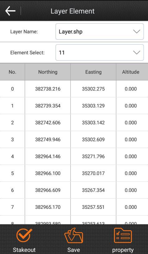
58 Figure6-15 Figure6-16
59 Chapter 7 Software introduce -- Calibrate Click Calibrate, there will pop up the interface shown as Figure 7-1. There are three submenus, including Site calibration, calibration point and calibration sensor. 7.1 Site Calibration Figure 7-1 In general, GPS receiver output data is WGS-84 latitude and longitude coordinates, the coordinates need to be converted to the construction measured coordinates, which requires coordinate conversion parameters are calculated and set the conversion parameters of software, it is the main tool to complete this work. There are three coordinates convert methods, including four parameter + elev _correction, seven parameter + four parameter + elev_correction and seven parameter. The users need to consider which method should be used based on the known point.
60 Four parameter: At least two coordinates of control point should be known, which are in arbitrary coordinate system. It is the parameter that is used to perform a plane conversion between different coordinate systems within the same ellipsoid. Parameters include: four values (translate northing, translate easting, rotation and scale), the scale should be infinitely close to 1. Seven parameter: At least three coordinates of control point should be known, which are in arbitrary coordinate system. It is the parameter that is used to perform Space rectangular coordinate transformation within different ellipsoids. Parameters include: seven values ( Δ X, ΔY, ΔZ,Δα, Δβ,Δγ,scale). In general, the control point distribution directly determines the level of high and low and four parameters to control. Using four parameters for RTK measurement method can be in a small range (20-30 square kilometers), make the measurement point in plane coordinate and cooperate between the precision of elevation control net with known very well, as long as the coordinate point collection of two or more than two places, but in a wide range of measure (for example, dozens of hundreds of square kilometers), transformation parameters often can't play for increasing accuracy of plane and elevation in part of the scope, seven parameter method should be used at this moment. You first need to make measurements and leveling control, in the area known control point coordinates do static control, and then the network adjustment prior to the survey area is selected a control point A as static net adjustment WGS84 reference station. Use A static Device at A fixed point measure single point positioning of more than 24 hours (this step in the test zone is relatively small, relatively low accuracy of cases can be omitted), and then imported into the software in single point positioning point at which total recorded, the average as A point of WGS84 coordinate, as A result of long time observation, the absolute accuracy should be within 2 meters, and then to three dimensional control network adjustment, you need take point A WGS84 coordinate as known coordinate, to calculate other points of 3 d coordinates, but at least more than three group, after the input to calculate the seven parameters.
61 The four parameter is used to plane conversion, it also needs to horizontal adjustment. When using horizontal adjustment, if there are less than three points elevations used to calculate, the parameter of horizontal adjustment is weighted average. If there are 4-6 points elevations used to calculate, the parameter of horizontal adjustment is plane fitting. If there are more than 7 points elevations used to calculate, the parameter of horizontal adjustment is surface fitting. How to calculate the convert parameter? In general, assuming that we use the three known points A, B, C to calculate the conversion parameters, then first we should know the GPS original record WGS-84 coordinates and local coordinates of A, B, C three points. There are two methods to get the GPS original record WGS- 84 coordinates of A, B, C points. First method, set up static control network, then get the WGS 84 coordinates from the GPD recording of the post-processing software. Second method, GPS rover records the GPS original WGS-84 coordinates in a fixed solution when no correction parameters are active. Click calibrate ->site calibrate, there will be the interface shown as Figure 7-2. You can do eight operations in this interface, including add, edit, delete, options, calculate, import, export and close.

62 Figure7-2 Figure7-3 Click add, there will pop-up the interface shown as Figure 7-3. There are two methods to set the know point coordinates: first method, click to get the coordinates from the points library; second method, input the name, northing, easting and elevation directly. Then set the WGS84 geodetic coordinates, and click OK to add the first group of coordinates. The remaining coordinates can be added in this way, until you have added all the coordinates which are participated in the parameter calculation. Select a coordinate in Site calibration and click edit, you can edit the parameters of this point, including known coordinates, WGS84 geodetic coordinates and options. Then click OK to save the changes. Select a coordinate in Site calibration and click delete, then all the data about this point could be deleted from site calibration. Click Options, there will pop up the site calibration settings shown as Figure 7-4. There are three coordinates convert methods, including four parameter + elev_correction, seven


63 parameter + four parameter + elev_correction and seven parameter. The four parameter model concludes horizontal adjustment and four parameter. Vertical control concludes weighted average, plane fitting, Surface fitting. The horizontal accuracy limit and vertical accuracy limit could be changed according to actual needs. Click Import, you can import the *.COT file, which convenient coordinate input. Click export, you can export and save the coordinates in site calibration to *.COT file. When you need to use these coordinates next time, you can import and don t need to re-input. After all the coordinates are entered, please click calculate, there will pop up the GPS parameter report shown as Figure 7-5. Click return, it will return to the site calibration interface, and when you click Close, there will pop up the prompt are you sure to apply calculated parameter model to the current project? shown as Figure 7-6. If you want to apply this parameter, please click OK. If you don t like to apply this parameter, please click cancel. After you apply the parameter, the original WGS-84 coordinates in the current project points library will be converted to the same coordinate system coordinates as the known points according to the parameters. Whether the calculation results are accurate or reliable, it can be checked by going to another known point.


64 7.2 Calibrate Point Figure7-4 Figure7-5 Figure7-6 Click calibrate-> calibrate point, there will pop up the interface as shown in Figure 7-7. SurvX has two kinds of calibrate point methods. Base point calibration, using the base coordinates before conversion and the current base coordinates to calibrate. Marker point calibration, using the coordinates of the points before conversion and the coordinates of the point after conversion to calculate. Base point calibration steps: 1. Click base point calibration to enter the interface shown as Figure Please input the known point coordinates (the base coordinates before conversion). There are two methods to input the coordinates: Click to get the coordinate from the points library. Or input the northing, easting and elevation directly. Click current base coordinates to set the antenna parameters, please refer to Figure 7-9. Figure7-7 Figure7-8 Figure Input the measured height, and select the measurement type.


65 4. Click Calculate to pop up the result as shown in Figure Then click Ok to return to the calibrate point interface. Note: The base point calibration should be used in a fixed solution. Marker point calibration steps: 1. Click marker point calibration to enter the calibration point interface shown as Figure Then input the known point coordinates, and click to get the current WGS84 coordinates. 2. Click OK to pop up the result. Then click OK to return to the calibrate point interface. Click view local offsets to view the local offsets, please refer to Figure Figure7-10 Figure7-11 Figure7-12 Calibrate point should be done on the basis of the already open transformation parameters. Local offsets are commonly used in the transformation parameters switch machine operations have been carried out and the base, or a work area of transformation parameters, can be directly input and local offsets parameters is, in fact, the use of a common point calculation of two different coordinates "three parameters", referred to as the local offsets in software. The following is the case where the calibrate point is used.

66 1. In the startup mode parameters of base, the use current coordinates is selected, and the base have been restarted or the position has been moved, the rover should calibrate point. 2. When the user knows the conversion parameter of the work area, the base could be set up at any place. Please input the conversion parameter, and the rover should calibrate point. 3. In the startup mode parameters of base, the input base coordinates is selected, and the base has been moved, the rover should calibrate point. 4. In the startup mode parameters of base, the input base coordinates is selected. If the base hasn t been moved, it just be restarted, the rover doesn t need to calibrate point. Chapter 8 Software introduction -- Tools Click Tools as shown in Figure8-1. It includes 6 submenus, namely Points Library, Coordinates Converter, Angle Converter, Perimeter and area, COGO Calculation, Calculator. Figure Points Library Click Tools - Points Library as shown in Figure8-2.
67 Figure8-2 Figure8-3 Figure8-4 Points library is for unified management on all kinds of coordinates. It adds point coordinates used in operation, helping invoke them in point setting-out. It supports quick search on coordinate points through entering point name or point No. in the Search box. Points Library consists of 8 contents, namely Add, Edit, Details, Delete, OK, Import, Options and Close. Click Add as shown in Figure8-3. Coordinates type includes Local Coordinate and Geodetic Coordinate. Property type includes Assistant point, Control point, Input point and Stakeout point. Input point name, plane coordinates (x, y, h) or latitude/longitude coordinates and Code after setting up Coordinate type and Property type to accomplish parameter set up of new coordinates. Choose any points in the Points Library. And click Edit to edit the Point name, plane coordinates (x, y, h) or latitude/longitude coordinates and Code, which applies to all points but Survey points. Click Details to check the Point name, Code, latitude/longitude coordinates, plane coordinates (x, y, h) and Type. Click Delete to delete the chosen point from the Points Library. Click Import and choose file format to import coordinates file, helping search and invoke coordinates in point setting-out. It supports Measurement data file(*.pd) and Custom format file(*.csv, *.dat and *.txt).

68 Click Option as shown in Figure8-4. Tick the point types to present as needed so as to filter other unwanted point types. It includes 7 options, namely Auxiliary Point, Survey Point, Control Point, Input Point, Calculate Point, Stake Point and Screen Point. 8.2 Coordinate Converter Click Tools - Coordinate Converter as shown in Figure8-5. Choose Conversion Mode, input coordinates, and click Calculate to accomplish coordinate conversion and check result as shown in Figure8-6. If it needs to save the converted coordinates, click OK and input the point name to save it to the coordinate library. There are two Conversion Modes: From WGS84 coordinates to current local coordinates, and From current local coordinates to WGS84 coordinates. There are two ways to set up the converting coordinates: one is directly inputting the Latitude, Longitude and Altitude or plane coordinates (x, y, h); the other is extracting points from Points Library. Figure8-5 Figure Angle Converter Click Tools - Angle Converter as shown in Figure8-7. It includes 6 angle formats, namely dd.mmssss, dd:mm:ss, dd mm'ss, dd(decimal), SS and Radian.
, and the result is as shown as in Figure8-8.")
69 The conversion goes in the following sequences:1. choose input angle format; 2. input angle; 3. choose angle converted format; 4. angle conversion accomplished, converted result presented in the angle box. For instance, input angle 23.25, convert it into dd(decimal), and the result is as shown as in Figure8-8. Figure8-7 Figure Perimeter and area Click Tools - Perimeter and area as shown in Figure8-9. Click Add to set up at least 3 coordinates and click Calculate to check the result, i.e., the Area and Perimeter of the graph composed by the set up points as shown in Figure8-10. Points can be chosen to edit and delete. Click Import to choose import coordinates file(*.dat and *.txt) and enter into the Coordinate list selection as shown in Figure8-11. The imported data can be filtered (through PointName or Code), searched and selected to determine the points used for Perimeter and Area calculation.

70 Figure8-9 Figure8-10 Figure COGO Calculation Click Tools - COGO Calculation as shown in Figure8-12. According to the known coordinates, it can Figure out position relations between point and point as well as between point and line. It includes Azimuth and Range, Angle offset, Vector, Two Lines Angle, Four known points, Two Points Two Lines, Two Points Two Angles, Two Points Lines Angles and One Point Line Angle Azimuth and Range Click Tools - COGO Calculation - Azimuth and Range as shown in Figure8-13. Set Start Point and End Point and click Calculate to check the result of Plane distance, Azimuth, Elevation difference, Ratio of slope and Vector, as shown in Figure8-14. There are three ways to set points: 1. extract coordinates from Points Library; 2. acquire current GPS coordinates; 3. directly input values of Northing, Easting and Elevation.


71 Figure8-12 Figure8-13 Figure Angle offset Click Tools - COGO Calculation - Angle offset as shown in Figure8-15. Set Start Point, End Point and Offset Point, and then click Calculate to check the result of Start distance, End distance, Start Vertical Distance, End Vertical Distance, Offset Distance and Offset Angle as shown in Figure8-16.


72 Figure8-15 Figure Vector Click Tools - COGO Calculation - Vector as shown in Figure8-17. Set Start Point and End Point, and then click Calculate to check the result as shown in Figure8-18. Figure8-17 Figure8-18


73 8.5.4 Two Lines Angle Click Tools - COGO Calculation - Two Lines Angle as shown in Figure8-19. Set Start Point A, End Point B, Start Point C and End Point D, and then click Calculate to check the result as shown in Figure8-20. Figure8-19 Figure Four Known Points Click Tools - COGO Calculation - Four Known Points as shown in Figure8-21. Set Point A, Point B, Point C and Point D, and then click Calculate to obtain the point coordinates in chart as shown in Figure8-22. If it needs to save the calculated point, click OK to save it to the coordinate library.


74 Figure8-21 Figure Two Points Two Lines Click Tools - COGO Calculation - Two Points Two Lines as shown in Figure8-23. Set Line L1, L2, Point A and Point B, and then click Calculate to obtain the point coordinates in chart as shown in Figure8-24. If it needs to save the calculated point, click OK to save it to the coordinate library.

75 Figure8-23 Figure Two Points Two Angles Click Tools - COGO Calculation - Two Points Two Angles as shown in Figure8-25. Set Angle α, β, Point A and Point B, and then click Calculate to obtain the point coordinates in chart as shown in Figure8-26. If it needs to save the calculated point, click OK to save it to the coordinate library. Figure8-25 Figure Two Points Lines Angles Click Tools - COGO Calculation - Two Points Lines Angles as shown in Figure8-27. Set Line L1, Angle α, Point A and Point B, and then click Calculate to obtain the point coordinates in chart as shown in Figure8-28. If it needs to save the calculated point, click OK to save it to the coordinate library.


76 Figure8-27 Figure One Point Line Angle Click Tools - COGO Calculation - One Point Line Angles as shown in Figure8-29. Set Line L1, Angle α and Point A, and then click Calculate to obtain the point coordinates in chart as shown in Figure8-30. If it needs to save the calculated point, click OK to save it to the coordinate library. Figure8-29 Figure8-30
Cube-a Field Software User Manual 4.0 SUITE.
 Cube-a Field Software User Manual 4.0 SUITE www.stonexpositioning.com Contents Software Introduction... 3 1. Cube-a installation and uninstallation... 4 Cube-a Installation... 4 1.1 Cube-a First Run...
Setup a VSN Survey Style Using Trimble Access (MiFi Card)
") Setup a VSN Survey Style Using Trimble Access (MiFi Card) California Surveying & Drafting Supply Technical Support Services Notes: This tutorial is designed for users with a MiFi Card/VSN Setup. In order
Setup a VSN Survey Style Using Trimble Access (MiFi Card) California Surveying & Drafting Supply Technical Support Services Notes: This tutorial is designed for users with a MiFi Card/VSN Setup. In order
Lecture ID: WT
 GNSS Online Lecture # 1 Lecture ID: WT-103-401 Lecture Topic: GNSS Data Processing in RTKLIB Dinesh Manandhar Center for Spatial Information Science The University of Tokyo Contact Information: dinesh@iis.u-tokyo.ac.jp
Configuring Esri s Collector 10.4 on Android with your Arrow receiver
 Configuring Esri s Collector 10.4 on Android with your Arrow receiver Before the first step, make sure that you have initially paired your Arrow with your Android device. If not, we suggest you to download
User s guide December 2011
 User s guide User s guide December 2011 WARNINGS In writing this manual every care has been taken to offer the most updated, correct and clear information possible; however unwanted errors are always
QUICK START GUIDE. SOLO Forest
 QUICK START GUIDE SOLO Forest Software Installation 1. For PC installation, run the.msi file. 2. For Mobile device installation, copy the.cab file onto the device 3. Run the.cab file Starting the Program
Hi-Survey Software User Manual Manual Revision File number Revision Revision Date Level Description I
 Hi-Survey Software User Manual Hi-Target Surveying Instrument Co., Ltd. All Rights Reserved Hi-Survey Software User Manual Manual Revision File number Revision Revision Date Level Description I Hi-Survey
FOIF_Survey User Manual
 FOIF_Survey User Manual Bluetooth connection Version2.3 Suzhou FOIF Co.,Ltd. 2 Contents 1. START RTK WORKING MODE...5 1.1 FOIF SURVEY CONTROLLER SOFTWARE INTRODUCTION...5 1.2 CREATE A NEW JOB...7 1.3 CONNECT
DPS900 SOFTWARE QUICK REFERENCE CARD FOR PILING OPERATORS
 DPS900 SOFTWARE QUICK REFERENCE CARD FOR PILING OPERATORS This document contains information for piling operators on how to use the Trimble DPS900 software. For information for supervisors, please refer
User Manual For TX204B/TX204G/TX306 Receivers
 User Manual Version V1.0-20171124 User Manual For TX204B/TX204G/TX306 Receivers 2017 Tersus GNSS Inc. All rights reserved. Sales & Technical Support: sales@tersus-gnss.com & support@tersus-gnss.com More
TRIMBLE ACCESS TRIMBLE ACCESS PROJECTS AND JOBS GUIDE
 TRIMBLE ACCESS TRIMBLE ACCESS PROJECTS AND JOBS GUIDE Version 2018.10 Revision A August 2018 Contents Projects & jobs 3 Managing projects 6 To create a local project 7 File transfer 7 Trimble data folders
APS-3 with FieldGenius Configuration Manual
 APS-3 with FieldGenius Configuration Manual Version 1.3 Table of contents 1 Getting Started... 2 1.1 Hardware requirements... 2 1.2 Installing FIELDGenius... 2 2 Septentrio FIELDGenius Startup... 3 2.1
TRIMBLE ACCESS TRIMBLE ACCESS PROJECTS AND JOBS GUIDE
 TRIMBLE ACCESS TRIMBLE ACCESS PROJECTS AND JOBS GUIDE Version 2018.00 Revision A June 2018 Contents Projects & jobs 3 Managing projects 6 To create a local project 7 File transfer 8 Trimble data folders
Setup a VSN Survey Style Using Trimble Access (Bluetooth Phone)
") Setup a VSN Survey Style Using Trimble Access (Bluetooth Phone) California Surveying & Drafting Supply Technical Support Services Notes: This tutorial is designed as a tutorial for users with a cell phone/vsn
Setup a VSN Survey Style Using Trimble Access (Bluetooth Phone) California Surveying & Drafting Supply Technical Support Services Notes: This tutorial is designed as a tutorial for users with a cell phone/vsn
Evidence Recorder Release Notes
 Evidence Recorder 7.1.0 Release Notes Released on: August 20, 2010 Important Notes We will be dropping support for several older builds of Evidence Recorder including: Allegro CE, Toughbook, Recon.Net,
User manual. TopoL Mobile 3.0. TopoL Software, s.r.o.
 User manual TopoL Mobile 3.0 TopoL Software, s.r.o. 2005-2012 TopoL Software, s.r.o. All rights reserved. TopoL is registered trade mark of TopoL Software, s.r.o. Obsah Content BASICS... 5 INSTALLATION...
Table of Contents 1 PURPOSE SCOPE DEFINITIONS PROCEDURE... 5
 Table of Contents 1 PURPOSE... 3 2 SCOPE... 3 3 DEFINITIONS... 4 4 PROCEDURE... 5 4.1 Overview - Performing a Site Calibration... 5 4.1.1 Upload Mine Grid Control... 6 4.1.2 Obtain SSM Data... 7 4.1.3
FieldGenius 2005 Ver 1.2 MicroSurvey Software, Inc. 2005
 New Functionality GPS Measurements Two new options in Program Settings that will speed up the measurement process when using an RTK receiver. Auto GPS Stats If this is turned on, during a measurement if
Release 4.1. Description
 Leica MobileMatriX Release 4.1 Products - Options Packages - Hardware Description Leica MobileMatriX 4.1 Leica Geosystems, 2004-2010 1 PRODUCTS Three different Editions are available: Standard Edition
Scepter / Scepter II Getting Configured for Real Time Networks with an Internet Hot Spot
 a. Turn Your Mi-Fi, Cell Phone or other Internet Hot Spot On b. Turn Your Scepter Data Collector On 1 c. In the center of the data collector tap Wi-Fi a. Tap Menu in the bottom Right Corner and then Wi-Fi
CHC Geomatics Office 2.0 User Guide
 CHC Geomatics Office 2.0 User Guide Revision 1.0 July 19, 2018 Table of Contents Table of Contents Table of Contents... 2 Preface... 11 Introduction... 11 Experience Requirements... 11 Technology and Service...
Box Calibration: Here I entered points 3 and 4 which are the only control points given to us in the plans.
 Box Calibration: Trimble machine control does not like files that are derived from State Plane Coordinates or files that contain a Geoid. Trimble representatives want everyone to do a site calibration
User s guide. November LSE S.r.l. All rights reserved
 User s guide November 2016 2016 LSE S.r.l. All rights reserved WARNING In writing this manual every care has been taken to offer the most updated, correct and clear information possible; however unwanted
TcpGPS. User Manual. Installation. The steps below must be followed:
 TcpGPS User Manual Installation The steps below must be followed: 1. Decompress the file TcpGPSSetup.zip. 2. Execute the file vcredist_x86_vs2008.exe. This application will install the libraries required
APS-3 with Seismic Surveyor
 APS-3 with Seismic Surveyor Configuration Manual Revision 1.01 Page 1 APS-3 with Seismic Surveyor, Configuration Manual 2011 ALTUS Positioning Systems Inc. All rights reserved. ALTUS, the ALTUS logo, and
User s guide. November LSE S.r.l. All rights reserved
 User s guide November 2015 2015 LSE S.r.l. All rights reserved WARNING In writing this manual every care has been taken to offer the most updated, correct and clear information possible; however unwanted
Support. TerraSync. Advanced Data Collection Techniques MGIS. Summary. Advanced Data Collection Options
 TerraSync MGIS Advanced Data Collection Techniques Support Summary Advanced data collection methods offer time-saving techniques for efficient field work. Step-bystep instructions are provided for: Advanced
BRx6 Sensor Calibration Using SurvCE/SurvPC
 OVERVIEW BRx6 Sensor Calibration Using SurvCE/SurvPC The BRx6 internal sensors (tilt, accelerometer and compass) must be calibrated in order to use the electronic bubble and tilted pole corrections in
Topcon GRS-1 1 Receiver Field Preparation
 Topcon GRS-1 1 Receiver Field Preparation What do you need to know to get started with your Topcon GRS-1? Topcon GRS-1 Receiver - Field Preparation Some Common Questions Which TopSURV modules do I buy?
General GPS TPS ROB X POLE VOL RDN RPL Jobs management System settings (units, precision, parameters, etc.)
") XPAD Survey Modules XPAD Survey GPS TPS XPOLE General GPS TPS ROB XPOLE VOL RDN RPL Jobs management System settings (units, precision, parameters, etc.) Instruments GPS GPS TPS ROB XPOLE VOL RDN RPL Instrument
XPAD Survey Modules XPAD Survey GPS TPS XPOLE General GPS TPS ROB XPOLE VOL RDN RPL Jobs management System settings (units, precision, parameters, etc.) Instruments GPS GPS TPS ROB XPOLE VOL RDN RPL Instrument
FieldGenius 2010 Release Notes
 FieldGenius 2010 Release Notes This document contains the release notes for all FieldGenius 2010 releases. The latest release notes can be found at the end of the document. FieldGenius 2010 4.2.0 (Released
THALES NAVIGATION. FAST Survey. Field Guide.
 THALES NAVIGATION FAST Survey Field Guide www.thalesnavigation.com Printed in France. Part Number: 630887-01, Revision A. No part of this publication or the computer programs described in it may be reproduced,
USER S MANUAL v.2. Settop CellXtrem
 USER S MANUAL v.2 Settop CellXtrem Rev. January 2016 USER S MANUAL 2 Index Index... 2 Settop CellXtrem... 3 Become familiar with the Settop CellXtrem... 4 Battery... 4 Coverage Level... 4 Client LED (Rover)...
MaCORS Quick Guide. Rover Configuration for Topcon GR 3 using Carlson SurvCE 2.x & Internal CDMA Modem
 MaCORS Quick Guide Rover Configuration for Topcon GR 3 using Carlson SurvCE 2.x & Internal CDMA Modem This Quick Guide outlines configuring the Topcon GR 3 with Carlson SurvCE & Internal CDMA modem to
Leica Captivate. Software Release Notes. Field Controllers: CS20, CS35 Total Stations: TS16, TS60, MS60, TS13 GNSS Sensors: GS18 T
 Leica Captivate v4.10 Software Release Notes Product Leica Captivate Field Controllers: CS20, CS35 Total Stations: TS16, TS60, MS60, TS13 GNSS Sensors: GS18 T Release date 10 th December 2018 Maintenance
Introduction to Solo Forest
 Introduction to Solo Forest Project Settings Collecting Data Office Procedures - Exporting Shapefiles - Syncing with the PC - Transferring files Opening Solo Forest To open Solo Forest, select Start >
DAT38MK2 Version 1.12
 COMPUTER PROGRAM MANUAL (SURVEY DATA REDUCTION MANUAL) DAT38MK2 Version 1.12 June, 2011 Geonics Limited 1745 Meyerside Drive, Mississauga, Ontario, Canada L5T 1C6 Tel: (905) 670 9580 Fax: (905) 670 9204
Getting started guide
 GEOGIS Getting started guide Version 14.097 Revision C October 2015 STONEX Srl Via Cimabue 39 20851 -Lissone (MB) Italy Phone +390392783008 ; +390392785575 Fax+390392789576 www.stonexpositioning.com Contents
USER GUIDE. Trimble SCS900 software
 USER GUIDE Trimble SCS900 software Version 3.5.1 Revision A April 2016 1 Corporate Office Trimble Navigation Limited 935 Stewart Drive Sunnyvale, CA 94085 USA www.trimble.com Heavy Civil Construction Division
Product Leica Infinity. Date Nov 30 th, From Kevin Hanson
 Product Leica Infinity Date Nov 30 th, 2017 From Kevin Hanson Leica Geosystems AG Heinrich-Wild-Strasse CH-9435 Heerbrugg Switzerland www.leica-geosystems.com Table of Contents 1 About this Release...
GPS SOFTWARE & MISSION PLANNING
 GPS SOFTWARE & MISSION PLANNING GPS & GIS Fall 2017 Mission Planning Online Mission Planning http://www.gnssplanningonline.com Settings Tab Satellite Library Elevation Number of Satellites Visibility Skyplot
This document contains a list of all changes, new features, bug fixed introduced in this last version of X PAD Survey.
 News X PAD Survey - January 2014 X PAD Survey 2.5.5 This document contains a list of all changes, new features, bug fixed introduced in this last version of X PAD Survey. GPS X-Y RSM: X and Y RMS accuracy
Evidence Recorder Release Notes
 Evidence Recorder 6.0.0 Release Notes Released on: October 5, 2009 Licensing Changes This release has had one big change and that is a new licensing system that gives us more flexibility to add different
ESRI ArcPad 7.1 Quick Reference
 ESRI ArcPad 7.1 GPS POSITION WINDOW SATELLITE SKYPLOT Shows the almanac of which satellites should be available. Black: Available and used for calculating the GPS position Blue: Available but not used
Please read this manual carefully before you use the unit and save it for future reference.
 ANDROID STEREO RECEIVER Please read this manual carefully before you use the unit and save it for future reference. Installation Precaution: 1. This unit is designed for using a 12V negative ground system
DASHBOARD OPERATION MANUAL. Machine Control, Inc.
 DASHBOARD OPERATION MANUAL Machine Control, Inc. INTEGRATE YOUR DATA With highly accurate topographic data describing your job site, its easy to envision and design a multiphase system to address your
DIRT OPERATION MANUAL. Machine Control, Inc.
 DIRT OPERATION MANUAL Machine Control, Inc. WELCOME TO DIRT Where precision land moving and shaping operations matter, you need Dirt machine control software. This program can import most design files,
TECHNICAL NOTES SURVEY PRO WITH TSX
 SURVEY PRO WITH TSX TECHNICAL NOTES Survey Pro software from TDS is the data collection solution of choice for most North American surveyors 1. And with the addition of the Trimble TSX (Trimble Systems
X PAD Construction 2.5.5
 News X PAD Construction January 2014 X PAD Construction 2.5.5 This document contains a list of all changes, new features, bug fixed introduced in this last version of X PAD Construction. GPS RTCM3.1: RTCM3.1
Topcon Link Quick Reference Guide
 Topcon Link Quick Reference Guide Part Number 7040-0027 Rev B Copyright Topcon Positioning Systems, Inc. May, 2003 All contents in this manual are copyrighted by Topcon Positioning Systems, Inc. All rights
Menu Updates The main menus have been revised and updated to provide a more consistent user experience. [F3079, F3085, F3098]
![Menu Updates The main menus have been revised and updated to provide a more consistent user experience. [F3079, F3085, F3098]](/thumbs/72/67082656.jpg "Menu Updates The main menus have been revised and updated to provide a more consistent user experience. [F3079, F3085, F3098]") NEW FEATURES Menu Updates The main menus have been revised and updated to provide a more consistent user experience. [F3079, F3085, F3098] Project Manager The Project Manager was modified to allow quicker
NEW FEATURES Menu Updates The main menus have been revised and updated to provide a more consistent user experience. [F3079, F3085, F3098] Project Manager The Project Manager was modified to allow quicker
GLONASS SHIELD USER MANUAL
 GLONASS SHIELD USER MANUAL 11 MARCH, 2013 THANK YOU FOR BUYING OUR PRODUCT! Congratulations! You have purchased our GLONASS/GPS Shield expansion board used to determine geographical coordinates and time
REFERENCE. Section 6. Field Use Tutorial 2-1
 REFERENCE Section 6 Field Use Tutorial 2-1 REFERENCE 2-2 Field Use Overview RTK GPS support is an additional feature in Sitework 4D, which must be purchased separately. In addition to creating takeoffs
SCS900 SITE CONTROLLER SOFTWARE USER GUIDE
 SCS900 SITE CONTROLLER SOFTWARE USER GUIDE Version 3.61 Revision A July 2017 Corporate Office Trimble Inc. 935 Stewart Drive Sunnyvale, CA 94085 USA www.trimble.com Product Limited Warranty Information
NS3Kview Quick-Start Guide
 NS3Kview Quick-Start Guide Issue: P00 Bulletin NS51-QSG Revision P00 Date 1 June 2011 TABLE OF CONTENTS 1. DISCLAIMER... 3 2. DISTRIBUTION... 3 3. INSTALLING NS3KVIEW... 3 4. INTRODUCTION... 4 5. GETTING
Version 2.0 English. Leica GPS900 Technical Reference Manual
 Version 2.0 English Leica GPS900 Technical Reference Manual Introduction Purchase Product identification Congratulations on the purchase of a GPS900 Series instrument. To use the product in a permitted
NAV31. User s Manual GEOMAR SOFTWARE INC. Tel: Fax:
 TrackMaker NAV31 Version 1.34 for Windows CE.NET and Allegro CX Field Computer data acquisition & navigation software for the Geonics EM31 and GPS receiver User s Manual GEOMAR SOFTWARE INC. Tel: 905.306.9215
Using the Leica Rover. A guide to locating And capturing locations Using the Leica GPS1200 Rover. Cleveland Utilities
 Using the Leica Rover A guide to locating And capturing locations Using the Leica GPS1200 Rover Cleveland Utilities Last Updated: Nov 23, 2004 Table of Contents Title Page Microstation to Field...1 4 Field
Release Notes SPECTRA PRECISION SURVEY OFFICE. Version
 Release Notes SPECTRA PRECISION SURVEY OFFICE Version 3.90.1 Corporate office: Spectra Precision 10368 Westmoor Drive Westminster, CO 80021 USA www.spectraprecision.com Copyright and trademarks: 2005-2017,
MobileMapper CE FAQ. 8 September Thales MobileMapper CE FAQ Page 1
 MobileMapper CE FAQ 8 September 2005 What is MobileMapper CE? MobileMapper CE is the next generation handheld GIS mobile mapping device from Thales. MobileMapper CE offers integrated Bluetooth wireless
version 1.03 GPS Information User Manual
 version 1.03 GPS Information User Manual page 2 GPS Information Installation Procedure You can use the "GPSinfo.exe" program to verify that the your GPS device is correctly confi gured and under a proper
Doc #: IDI06-11F Rev: 1.3 Issued: 22/02/18. Well Seeker PRO How To Guide Rev 1.3. Page 1 of 26
 Well Seeker PRO How To Guide Rev 1.3 Page 1 of 26 Contents 1.0 - Getting Started... 4 1.1 - Display... 4 2.0 - Creating a new Well... 5 2.1 - Unit Selection... 5 2.2 - New Instant Plan / Survey... 6 2.3
SXblue Premier GNSS Network RTK Receiver. User Manual
 SXblue Premier GNSS Network RTK Receiver User Manual 1 Directory Table des matières Chapter Ⅰ Brief Introduction... 4 1.1. Introduction... 4 1.2. Main Features... 4 1.2.1. Smart platform... 4 1.2.2. WiFi
TECHNICAL NOTES TRIMBLE SURVEY CONTROLLER SOFTWARE
 TRIMBLE SURVEY CONTROLLER SOFTWARE TECHNICAL NOTES The Trimble Survey Controller software is the data collection solution that will make your survey work faster, easier, and more productive than ever before.
3. Map Overlay and Digitizing
 3. Map Overlay and Digitizing 3.1 Opening Map Files NavviewW/SprayView supports digital map files in ShapeFile format from ArcView, DXF format from AutoCAD, MRK format from AG-NAV, Bitmap and JPEG formats
Leica Captivate. Software Release Notes. Field Controllers: CS20, CS35 Total Stations: TS16, TS60, MS60. Release date 5 th March 2018
 Leica Captivate v3.20 Software Release Notes Product Leica Captivate Field Controllers: CS20, CS35 Total Stations: TS16, TS60, MS60 Release date 5 th March 2018 Maintenance date 5 th March 2018 Available
This firmware is protected and can only be loaded onto instruments with valid firmware (software) Maintenance date.
 Maintenance date.") Products TPS1200, GPS1200, RX1250 From System 1200 Product Management Date 17 th July, 2008 DVD ROM Leica SmartWorx DVD (Art. No. 755806) Version SmartWorx v6.00 Download http://downloads.leica-geosystems.com/downloads/index.htm
Products TPS1200, GPS1200, RX1250 From System 1200 Product Management Date 17 th July, 2008 DVD ROM Leica SmartWorx DVD (Art. No. 755806) Version SmartWorx v6.00 Download http://downloads.leica-geosystems.com/downloads/index.htm
Panasonic VRF Software. New features of VRF software
 Panasonic VRF Software New features of VRF software April 2013 1 Contents: Mounting scheme... 5 1. Import building scheme into software... 5 1.1. Export building scheme as DXF from AutoCAD... 5 1.2. Export
Roadway Alignments and Profiles
 NOTES Module 15 Roadway Alignments and Profiles In this module, you learn how to create horizontal alignments, surface profiles, layout (design) profiles, and profile views in AutoCAD Civil 3D. This module
3.1 Units. Angle Unit. Direction Reference
 Various settings allow the user to configure the software to function to his/her preference. It is important to review all the settings prior to using the software to ensure they are set to produce the
GPS receiver Trimble Juno 3B
 STARTUP & CONFIGURATION Press the power button for a few seconds Open the windows menu (by selecting on screen or pushing the windows button) Select TerraSync > Professional Edition. The upper pull down
Manual Revision Situation
 HGO Data Post Processing Software Package Manual Manual Revision Situation Revision Date Revision Level 2012-07-27 1 Description HGO Data Post Processing Software Package Manual I HGO Data Post Processing
GNSS/GPS Overview for the DEP Status and Trend Networks
 GNSS/GPS Overview for the DEP Status and Trend Networks Florida Department of Environmental Protection Tom Biernacki Video of this presentation is posted at https://fldeploc.dep.state.fl.us/appdata/status/sol
CC888 EZcarsharing Control System & T-Box Communication Protocol-V3.5
 CC888 EZcarsharing Control System & T-Box Communication Protocol-V3.5 This Protocol is used for communication between car sharing control system and the platform server, command & message from server to
Using ArcPad and GPS Correct 3.31
 Using ArcPad 10.02 and GPS Correct 3.31 Class objectives: Understanding GPS Configuring ArcPad for data collection Field data capture with ArcPad Data collection Navigation Offsets Editing Creating New
Post-Processing with MobileMapper Office and NGS CORS data
 Post-Processing with MobileMapper Office and NGS CORS data 23 January 2007 1. Just below the MobileMapper Office (MMO) Map Display Area, you will see the Differential Correction window. Click the Show
OPERATING INSTRUCTIONS. EM34xp Version June, 2007
 OPERATING INSTRUCTIONS EM34-3 DATA LOGGING SYSTEM FOR WINDOWS XP BASED FIELD COMPUTER EM34xp Version 1.02 June, 2007 Geonics Limited 1745 Meyerside Drive, Mississauga, Ontario, Canada L5T 1C6 Tel: (905)
Leica Captivate. Software Release Notes. Field Controllers: CS20, CS35 Total Stations: TS16, TS60, MS60. Release date 1 st December 2017
 Leica Captivate v3.00 Software Release Notes Product Leica Captivate Field Controllers: CS20, CS35 Total Stations: TS16, TS60, MS60 Release date 1 st December 2017 Maintenance date 1 st December 2017 Available
Software Update Release Notes: GSG StudioView Scenario Builder Software GSG StudioView Version 4.5 Release Notes
 Software Update Release Notes: GSG StudioView Scenario Builder Software GSG StudioView Version 4.5 Release Notes Spectracom Corp., Rochester NY, USA December 21, 2015 GSG StudioView offers an easy way
Tracking Platform Operation
 Tracking Platform Operation This platform is designed for CCTR-8XX series GPS Tracker, Language can be selected from the login page : www.999gps.net, every tracker have a unique user name and password,
Trimble Survey Controller. Release Notes
 Trimble Survey Controller Release Notes Version 10.5 Revision A September 2002 Corporate Office Trimble Navigation Limited Engineering and Construction Division 5475 Kellenburger Road Dayton, Ohio 45424-1099
Quick Guide for egps
 Quick Guide for egps Effective 08/23/11 Page 1 of 13 Legal Information Address: Freiheitstraße 124 126, 15745 Wildau Germany Telephone: +49 3375 527366 E-Mail: support@eentwicklung.net All contents in
GSR Reference Station Software
 GNSS Reference Station GSR Reference Station Software Reference Manual GNSS Reference Station Tplljb GSR Reference Station Software Version 7.2.1 Preliminary For Internal Use Only Reference Manual Preliminary
ATNS. USING Google EARTH. Version 1
 ATNS USING Google EARTH Version 1 ATNS/HO/Using Google Earth Page 1 25/04/2013 CONTENTS 1. BASIC SETUP 2. NAVIGATING IN GOOGLE EARTH 3. ADDING OBJECTS TO GOOGLE EARTH 4. USER HELP REFERENCES ATNS/HO/Using
3DMC / 3DXi Create a network equipment configuration. 2. Enter IP address & NTRIP information.
 3DMC / 3DXi 6.11.03 1. Added Network & Modem Support Added support for Wavecom and SmallTouch modems. Added RTCM 3.0 support Improvements made connecting to GPS networks. Network setup example: 1. Create
OPERATING INSTRUCTIONS. EM38xp Version November, 2006
 OPERATING INSTRUCTIONS EM38 DATA LOGGING SYSTEM FOR WINDOWS XP BASED FIELD COMPUTER EM38xp Version 1.01 November, 2006 Geonics Limited 1745 Meyerside Drive, Mississauga, Ontario, Canada L5T 1C6 Tel: (905)
DragNet (Fixed WiMAX) d Manual version 1.1
 d Manual version 1.1") DragNet (Fixed WiMAX) 802.16d Manual version 1.1 Projector User Manual Installation...... 2 Quick Start... 2 Create a Projection...... 3 Getting a Quick Projection........ 6 Procedure for Creating a BVS
DragNet (Fixed WiMAX) 802.16d Manual version 1.1 Projector User Manual Installation...... 2 Quick Start... 2 Create a Projection...... 3 Getting a Quick Projection........ 6 Procedure for Creating a BVS
LT500 SERIES GETTING STARTED GUIDE GNSS HANDHELD RECEIVER
 il LT500 SERIES GETTING STARTED GUIDE GNSS HANDHELD RECEIVER Copyright Copyright 2014-2015 CHC Shanghai HuaCe Navigation Technology Ltd. All rights reserved. The CHC are trademark of Shanghai Huace Navigation
OPERATING INSTRUCTIONS. ICE31 Version August, 2005
 OPERATING INSTRUCTIONS ICE31 DATA LOGGING SYSTEM FOR FIELD COMPUTER Allegro CX Field PC ICE31 Version 1.01 August, 2005 Geonics Limited 1745 Meyerside Drive, Mississauga, Ontario, Canada L5T 1C6 Tel: (905)
Pocket-3D Reference Guide
 P O S I T I O N I N G S Y S T E M S Pocket-3D Reference Guide Part Number 7010-0628 Rev G Copyright Topcon Positioning Systems, Inc. June, 2010 All contents in this manual are copyrighted by Topcon. All
ZENDA Manager User Guide. Applicable Model: ZD-VT1
 ZENDA Manager User Guide Applicable Model: ZD-VT1 Change History File Name ZENDA Manager User Guide Created By Owen Cheng Project ZD-VT1 Creation Date 2016-01-18 Update Date 2016-02-02 Subproject User
MobileMapper 6 Frequently Asked Questions
 MobileMapper 6 Frequently Asked Questions 1. What is MobileMapper 6? MobileMapper 6 is an entry-level mapping device from Magellan. It is an affordable and easy-to-use, yet professional GPS/GIS receiver
William E. Dietrich Professor 313 McCone Phone Fax (fax)
") February 13, 2007. Contact information William E. Dietrich Professor 313 McCone Phone 510-642-2633 Fax 510-643-9980 (fax) bill@eps.berkeley.edu Project location: Northwest of the Golden Gate Bridge, San
February 13, 2007. Contact information William E. Dietrich Professor 313 McCone Phone 510-642-2633 Fax 510-643-9980 (fax) bill@eps.berkeley.edu Project location: Northwest of the Golden Gate Bridge, San
3DMC Reference Guide
 P O S I T I O N I N G S Y S T E M S 3DMC Reference Guide Part Number 7010-0911 Rev. B Copyright Topcon Positioning Systems, Inc. April, 2010 All contents in this manual are copyrighted by Topcon. All rights
Trimble s RoadLink Utility Tutorials
 Trimble s RoadLink utility is an interface between third-party road definitions and Trimble survey devices. It lets you import or key in road definitions, view them graphically, edit them if required,
Soil and Water Conservation Laboratory Standard Operating Procedure
 Soil and Water Conservation Laboratory Standard Operating Procedure Sherman 230, Soil and Water Conservation Laboratory, UH Mānoa Collecting GPS data with the Trimble handheld through ArcGIS & related
X90 GPS X90GPS RTK. 1 -
 X90GPS RTK : : 1 - www.nprco.com 3 3 3 4 4 4 4 4 5 5 5 10 11 12 12 14 14 15 16 16 18 19 19 19 20 20 21 22 22 25 28 31 31 32 36 36 36 36 37 39 41 44.1 1 1.2.2 2.1 2.1.1 2.1.2 2.1.3 2.2.3 3.1 3.2 3.2.1 3.2.2
Perpendicular Offsets - point picker is a check-box type button and will now remain in effect until switched off.
 New Functionality Raw File Viewer This now has a View button that allows the user to see the map in a split view. Tapping on certain records will show up as icons in the view. For example tapping an OC
K-Mobile User Manual for Smartphones
 K-Mobile User Manual for Smartphones Issue: 1 Rev A 8/17/2017 Legal Notices K-MATIC Blundellsands House, 34-44 Mersey View, Brighton le Sands, Liverpool, L22 6QB, UK www.k-matic.com Copyright and trademarks
Vector Compact-S (NMEA 0183) Vector Compact-N (NMEA 2000) Quick Installation Guide
 Vector Compact-N (NMEA 2000) Quick Installation Guide") Vector Compact-S (NMEA 0183) Vector Compact-N (NMEA 2000) Quick Installation Guide Seapilot VECTOR COMPACT-S NMEA 0183 (Serial) Kit Housing Screw Caps and O-ring Housing M6 Screws Mounting Base Front View
Vector Compact-S (NMEA 0183) Vector Compact-N (NMEA 2000) Quick Installation Guide Seapilot VECTOR COMPACT-S NMEA 0183 (Serial) Kit Housing Screw Caps and O-ring Housing M6 Screws Mounting Base Front View