6 Series Mill Controller Operation Manual
|
|
|
- Clare Jacobs
- 5 years ago
- Views:
Transcription

1 6 Series Mill Controller Operation Manual Date: 2015/11/13 Version: 1.3
2 2
3 Contents 1 Function Key and System Configuration Main Screen Sections CNC System Configuration Coordinate Explanation of Function Switch Coordinate Half Coordinate Clear Rel. Coord Clear All Rel. Coord Program Execute Delete Line Search/Replace File Manager Simulation Can Cycle Block Copy Teach Offset/Setting Workpiece Cord Tool Set Tool Tip Measurement User Parameter Setting Monitor Monitor Area of Machining Information Open File to Edit Simulation Switch MDI Input Parameter Set Tool Wear Set Start MPG Coordinate Work Record Clear Acum Cycle Time Graph Adjust Maintain Alarm
4 1.7.2 Network Setting Fast Diagnostic PLC Param Setting System Setting Backup System About Machine Operation Panel Operation Panel Text Key Description How to Operate 6 Series Controller System Status Not Ready Ready Busy Pause B-stop Machine Preparation Manual Function Machining Process Workpiece Preparation Workpiece Cord set Middle Func Tool Prepare Program Preparation and Execute Machining Specifying Machining Program Simu. Setting Machining Test Machining Monitor Alarm Processing Network Setting PC Setting File Transfer File Import File Export Appendix Release Note
5 4.2 Contact Window
6 1 Function Key and System Configuration 1.1 Main Screen Sections Meanings for Sections on the Display: 1. Present coordinate system 2. Working file name and machining command line 3. Title of interface (Current interface) 4. Date 5. Time 6. Data input 7. Display(Hint) 8. Status 9. Mode 10. Alarm 4
7 11. Function Key 1.2 CNC System Configuration 5

8 1.3 Coordinate Command F1 Coordinate Function Switch current coordinate system on the screen. Display the frequently use machining information. Use the function key POS, can switch to the current page quickly. PS: By pressing POS Key, you may jump from other page to this page interface. 6
9 1.3.1 Explanation of Function Coordinate Display Current screen can display 4 kind of coordinate system. Whenever users press F1 Switch Coordinate function key, the coordinate on the screen will switch between four different kinds of coordinates F (Feedrate) User input Feedrate (mm/min). Actual Feedrate of cutting tool (mm/min). Percentages of Feedrate S(Rotating Speed of Spindle ) User input Spindle speed (RPM). Actual speed of spindle (mm/min). Percentages of Spindle speed Run Time Machining Duration Part counter Number of parts that had been finished T (Tool No.) Current Tool no. and Tool compensation no. 7
10 1.3.2 Switch Coordinate Command F1 Coordinate F1 switch coordinate Function When users press F1 Switch Coordinate function key, the coordinate display on the screen will switch between four different kinds of coordinates Half Coordinate Command F1 Coordinate F2 Half Coordinate Function Relative coordinate divided by 2. Combined with Clear Rel. Coord. function, this function will calculate the middle point of the object. Operation Method Key in the axis that you want to calculate and then press Half Coordinate. Example Current Rel. Coord. of X axis is Key in X,and then press half coordinate. Current Rel. Coord. of X axis Will become
11 1.3.4 Clear Rel. Coord. Command F1 Coordinate F3 Clear Rel. Coord. Function Set the Relative Coordinate to zero. Operation Method Key in the axis that you want to calculate and then press Clear Rel. Coord. Example Current Rel.Coord.of X axis is Press X,and then press Clear Rel. Coord.. Current Rel. Coord. of X axis Will be set to Clear All Rel. Coord. Command F1 Coordinate F4 Clear All Rel. Coord. Function Clear all Relative Coordinate. Example Current X axis of relative coordinate is , Y axis is Press Clear All Rel. Coord. function key. Relative Coordinate of X and Y will be set to

12 1.4 Program Command F2 Program Function This function provides users program management and editing functions. Operation Method Users can use on the key pad to move the cursor to anywhere on the screen for editing purpose. With Page Up Page Down to switch the pages. With Home End can let the cursor jump between the top and end of the line. With the function key Prog/File can quickly switch between Program and File Manager 10
13 11
14 1.4.1 Execute Command F2 Program F1 Execute Function Execute current program and also change the screen to Monitor page. Note This function will be disabled during machining Delete Line Command F2 Program F2 Delete Line Function Delete a line where the cursor is located. 12

15 1.4.3 Search/Replace Command F2 Program F3 Search/Replace Function Quick search for every occurrence of a specific word or phrase and automatically replace text. Operation Method Press Search/Replace function key, then Replace box will appear, just enter the text that you want to search and replace for. 13
16 Find Next Command F2 Program F3 Search/Replace F1 Find Next Function Find Next Replace Command F2 Program F3 Search/Replace F2 Replace Function Replace with input text Operation Method Press F2 Replace to replace highlight string with new string. If you want to skip the current highlighted string, press F1 Find Next. 14
17 Replace All Command F2 Program F3 Search/Replace F3 Replace All Function Replace all search text with input text Modify Setting Command F2 Program F3 Search/Replace F4 Modify Setting Function Reset Search/Replace input. Operation Method Press F4 Modify Setting to reset the Search/Replace content. 15

18 1.4.4 File Manager Command F2 Program F4 File Manager Function This function key can manage all of the NC files within the data storage device. The device can be setting with Pr3213. Operation Method Use on the key pad to move the cursor to anywhere on the screen for editing purpose. With Page Up Page Down to switch the cursor between pages. Press ENTER on the key pad, to assign the current cursor file as the execute file, screen will show up with the program content and can enable to edit the program. 16
19 New File Command F2 Program F4 File Manager F1 New File Function Open a new file, that file will be the current edit file. Operation Method Press New File function key, a dialog box will appear, enter the new file name and press ENTER. Note Default file name has no file extension. If user want to create a new file with file extension such as *.NC, just enter the extension (*.NC) as well. The length of file name cannot be longer than 32 characters(include file extension) Copy File Command F2 Program F4 File Manager F2 Copy File Function Copy the file that remarked by cursor. Operation Method Use to move the cursor to the file that want to copy. Press Copy File function key. A dialog box will appear, enter the new file name. 17
20 Note Default file name has no file extension. If user want to create a new file with file extension such as *.NC, just enter the extension (*.NC) as well. The length of file name cannot be longer than 32 characters(include file extension) Delete File Command F2 Program F4 File Manager F3 Delete File Function Delete file that remarked by cursor. Operation Method Press F3 Delete File, checkbox will show up in front of the NC file within the File Manager monitor page. Use to select the delete file. Sub-function Key Select: Select file, can select more than one file and also can cancel the selection of one file. Select All: Select all files. Cancel Select: Deselect all files. Delete File: Delete all of the selected files. Delete All: Delete all file within the data storage device. Note Current Programming and machining file cannot be deleted. 18
21 File Transfer Command F2 Program F4 File Manager F4 File Transfer Function Transmit data between controller and outer device. 19
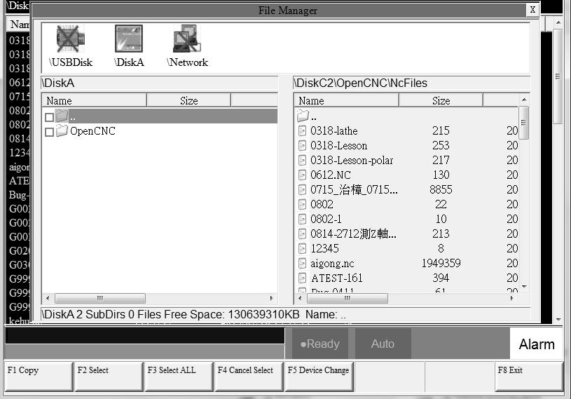
22 File Import Command F2 Program F4 File Manager F4 File Transfer F1 File Function Import Import outer file into controller Function Page Explanation The upper block shows the outer devices selection with the following choice. USBDisk DiskA Network USBDisk2 Left column shows data structure of the outer device. Right column shows data structure of the inner storage of the controller. Sub-function Explanation Copy: Copy the remarked file from the outer device to the controller. Select: Select or deselect each file. (Not available for folder) Select All: Select all files. Cancel Select: Deselect all files. Device Change: Change outer device selection. Operation Method Press F1 File Import, a dialog box will appear. Default outer device is USBDisk. 20
23 If you want to change the outer device, press F5 Device Change,switch the cursor to the desire device and press Enter, then the left column will change and show the data structure of selected device. Use to select file. Move the cursor to the import file and press F2 Select or Space to remark file. After remarked all of the import file, press F1 Copy then all of the remarked file will import into controller. 21
24 File Export Command F2 Program F4 File Manager F4 File Transfer F2 File Function Export Export files within controller to outer device. Function Page Explanation The upper block shows the outer devices selection with the following choice. USBDisk DiskA Network USBDisk2 Left column shows data structure of the outer device. Right column shows data structure of the inner storage of the controller. Sub-function Explanation Copy: Copy the remarked file from the outer device to the controller. Select: Select or deselect each file. (Not available for folder) Select All: Select all files. Cancel Select: Deselect all files. Device Change: Change outer device selection. Operation Method Press File Export, a dialog box will appear. Default outer device is USBDisk. 22
25 If you want to change the destination device, press F5 Device Change, switch the cursor to the desire device and press Enter, then the left column will change and show the data structure of selected device. Use to select file. Move the cursor to the export file and press F2 Select or Space to remark file. After remarked all of the export file, press F1 Copy then all of the remarked file will export from controller to outer device Execute Command F2 Program F4 File Manager F5 Execute Function Execute current program. and also change the screen to the monitor page. Operation Method Use to select file, and then press Execute the selected file will be the executive file. Note This function is invalid when machining. 23

26 1.4.5 Simulation Command F2 Program F5 Simulation Function Program simulation for the actual machining route. Capability of debug. Default display range will be the span of the full program. Simulation setting can be modified by F5 simulate Setting. 24
27 Step Command F2 Program F5 Simulation F1 Step Function Simulate the program block by block. Monitor the variation of the coordinate for single block Continue Command F2 Program F5 Simulation F2 Continue Function System will scan all of the programs and then do the simulation Zoom Command F2 Program F5 Simulation F3 Zoom Function Zoom in/out the simulation window. Operation Method Press F3 Zoom,there will be a block show up. Use to move the window up, down, left and right. Use Page Up Page Down to change the zooming area. Press ENTER to check the result. 25
. 2. Path Color Simulation path color. 26")
28 Graph Reset Command F2 Program F5 Simulation F4 Graph Reset Function Reset the simulation result to default Simu. Setting Command F2 Program F5 Simulation F5 Simu. Setting Function Setting the relative simulation item. Simulation Parameter 1. Color Provide 16 different colors(setting 0~15). 2. Path Color Simulation path color. 26
29 Provide 16 different colors(setting 0~15). 3. Cursor Color Color of cursor point Provide 16 different colors(setting 0~15). 4. RGB Value Except the 16 default color, user can define the color themself. 5. Draw Mode User can define the profile simulate plane. Plane can define are as below. XYZ XY YZ ZX YX ZY XZ 6. Setting quadrant User can define the quadrant of simulate plane. Quadrant can define are as below. First Second Third Fourth 27
30 7. Simulate Mode Setting profile simulate method. Simulation When user go to the Monitor page, simulation will show up automatically. System will scan the whole program and detect the simulation boundary, and then simulation will execute. No need to define the simulate boundary. Direct Draw When user go to the Monitor page, cursor will show up but simulation will not execute automatically. User need to define the simulation boundary first. When the machining starts, cursor will follow up as well. Not Simulation Close the simulation function. 8. View Angle Setting Under XYZ draw mode, by setting this parameter, simulation will show up with 3D. View angle can define are as below. Vertical Horizontal 28
31 9. Scope Scope can define are as below. Minimum X-Axis Y-Axis Z-Axis Maximum X-Axis Y-Axis Z-Axis 29

32 1.4.6 Can Cycle Command F2 Program Next F1 Can Cycle Function Because Syntec system provides many G codes and different G code has each function. When editing the program, this function can help user to edit G code easily. 30
33 Insert Cycle Command F2 Program Next F1 Can Cycle F1 Insert Cycle Function Insert the required G code. Operation Method Under the program edit mode, move the cursor to the desired location and press Insert Cycle. Follow the instruction and press OK, the desired G code will insert into the next line of current cursor Edit Cycle Command F2 Program Next F1 Can Cycle F2 Edit Cycle Function Edit the current cycle. Operation Method Move the cursor to the cycle and press Edit Cycle,a modify page will show up. Modify the contents and press OK, the contents of the current cycle will change. 31

34 1.4.7 Block Copy Command F2 Program Next F2 Block Copy Function Select, cut, copy and paste more than one line of programs. 32
35 Start Line Command F2 Program Next F2 Block Copy F1 Start Line Function Define the start line of block End Line Command F2 Program Next F2 Block Copy F2 End Line Function Define the end line of block Block Cut Command F2 Program Next F2 Block Copy F3 Block Cut Function Cut the block that had been selected Block Copy Command F2 Program Next F2 Block Copy F4 Block Copy Function Copy the block that had been selected Block Paste Command F2 Program Next F2 Block Copy F5 Block Paste Function 33
36 Paste the block that had been Block Cut and Block Copy. 34
37 Operation Method Move the cursor to the desire line and press Start Line and function key End Line enable. Press Page Up Page Down to select desired area. Press End Line,block between Start Line and End Line will be selected. 1. Function key End Line disable. 2. Function key Block Copy enable. 3. Function key Block Cut enable. 4. If Block Cut being use, the whole block that had been highlight will be cut off. 5. Function key Block Copy / Block Cut disable. 6. Function key Block Paste enable. Move the cursor to the desire location and press Block Paste, the content that had been cut or copied will paste at the cursor location. If Block Copy is used, the block that had been selected will not disappear. Note 35

38 If Block Cut is use, and do not paste the content immediately, the cut program will disappear. The contents of Block Cut can be pasted for only one time but the contents of Block Copy can be pasted for many times Teach Command F2 Program F6 Teach Function Move the machine table with MPG / JOG / INJOG to the destination and use Teach function, input the current absolute coordinate value to NC program. Omit the manual input problem. 36
39 Rapid Teach Command F2 Program F6 Teach F1 Rapid Teach Function Add the current absolute coordinate as the value of G00 Rapid Traverse function in current program Line Cut Teach Command F2 Program F6 Teach F2 Line Cut Teach Function Add the current absolute coordinate as the input value of G01 Linear Cutting function in current program Arc Cut Teach Command F2 Program F6 Teach F3 Arc Cut Teach Function Add current absolute coordinate as the input value of G02/G03 Circular Cutting function in current program. Operation Method Move the worktable to the arc center and press Arc Cut Teach, current absolute coordinate will be define as the arc center. Move the worktable to the ending of the arc and press Arc Cut Teach, current absolute coordinate will be define as 37
40 the ending of the arc. Controller will automatically calculate the relation between middle and end point and determine whether to use G02 or G03. The calculation result will be regarded as the input value of G02/G03 Circular Cutting function Cancel Arc Middle Command F2 Program Next F3 Teach F4 Cancel Arc Middle Function Clear the arc middle that had been set. If the arc middle are not being set, this function will not enable. 38
41 Point Teach Command F2 Program Next F3 Teach F5 Point Teach Function Move the worktable to the arc center and press Point Teach, current absolute coordinate will be input into the cursor location. 39

42 1.5 Offset/Setting Command F3 Offset/Setting 40
43 Function User can set up the coordinate system and tool offsets with this function. With the function key Offset/Setting can switch the page quickly to the Offset/Setting page. 41
44 1.5.1 Workpiece Cord. Command F3 Offset/Setting F1 Workpiece Cord. Function For workpiece coordinate setting purpose. System default will be G54 if there are no specific declaration with G54~G59.10 in the NC code. The External Shift will include into all the workpiece coordinate. Operation Method: Move the cursor with. Use PageUp PageDown to switch the pages. Note After setting the workpiece coordinate, user need to check the tool length again. 42
45 43
46 Mach. Coord. teach Command F3 Offset/Setting F1 Work Piece Cord. F1 Mach. Coord. Teach Function Set current mechanical coordinate value into work piece coordinate. Operation Method Move the worktable to the target location. Move the cursor to the relate work piece coordinate and press Mach. Coord. Teach Original value of workpiece coordinate will be replaced by the corresponding mechanical coordinate. Example Current mechanical coordinate of X axis is Current value of X axis of G54 is Move the cursor to G54 X axis. Press Mach. Coord. Teach, the value of X axis of G54 becomes
47 Rel. Coord. Teach Command F3 Offset/Setting F1 Work Piece Cord. F2 Rel. Coord. Teach Function Set current relative coordinate value into work piece coordinate. Operation Method Move the worktable to the target location. Move the cursor to the related work piece coordinate and press Rel. Coord. Teach Original value of workpiece coordinate will be replaced by the corresponding relative coordinate. Example Current relative coordinate of X axis is Current value of X axis of G54 is Move the cursor to G54 X axis. Press Rel. Coord. Teach, the value of X axis of G54 become
48 Aux. Coord. Teach Command F3 Offset/Setting F1 Work Piece Cord. F3 Aux. Coord. Teach Function Set the current cursor located work piece coordinate value as the aux. coordinate value. Aux. value appears after using middle function. Operation Method Using middle function to calculate the aux. coordinate value. Move the cursor to the desired work piece coordinate and press Aux. Coord. Teach Original value of workpiece coordinate will be replaced by the corresponding Aux. coordinate. Example Current mechanical coordinate of X axis is Current value of X axis of G54 is Move the cursor to G54 X axis. Press Aux. Coord. Teach, the value of X axis of G54 become Inc. Input Command F3 Offset/Setting F1 Work Piece Cord. F4 Inc. Input Function 46
49 Add the work piece coordinate value with the manual input value and restore into work piece coordinate again. Operation Method Move worktable to the target location. Input increment value. Move the cursor to the work piece coordinate and press Inc. Input Work piece coordinate will be replaced by the cursor located coordinate +input value. Example Current mechanical coordinate of X axis is Move cursor to the workpiece coordinate G54 of X axis Key in Press Inc. Input The coordinate of G54 X axis become

50 Middle Func. Command F3 Offset/Setting F1 Work Piece Cord. F5 Middle Func. Function Calibrate the middle point of the work piece before machining. Operation method Input the Middle Func calculated result into G54~G59 work piece coordinate. There are two kind of operation method for the Middle Func, one is manual and another is automatic. 48
51 Manual Function Mode of Middle Func. is 0. Move the tool with MPG to the edge of the workpiece XY axis. Record the machine coordinate and system will calculate the center point of the workpiece automatically. Operation method Move the measurement tool with MPG to Px1 point according to the figure and then press PX1 set. The system will input the current machine Coord. into PX1. Measure PX2 with the same method. Combine with PX2, system will compute the center point of PX1 and PX2 and set the result into Pxm and Aux. X Coord. Move the measurement tool with MPG to PY1 point according to the figure and then press PY1 set. The system will input the current machine Coord. into PY1. Measure PY2 with the same method. Combine with PX2, system will compute the middle point of PY1 and PY2 and set the result into Pym and Aux. Y Coord. The values of Pxm and Pym are the center point of the workpiece. In the WorkPiece Cord setting page, move the cursor to the relative coord, press F3 Aux. Coord. Teach then system will set the Aux Coord value into relate work piece coordinate. 49
52 Auto Function Mode of Middle Func. is 1. Auto middle func. is different from Manual func. User only needs to enter the dimension of the workpiece and enter the boundary coordinate. Move the tool to the start point, system will find out the center point of work piece automatically. Parameter Description Length I: length of Workpiece in X dimension Width J: width of Workpiece in Y dimension Safe Distance H: The distance between start point P2 and workpiece, in X or Y direction. Feedrate F: Auto detection speed. Safe altitude of Z Coordinate: safety distance for tool when moving as the P1 on the figure. Operation Method Move the tool to the safe altitude, as P1 point on the figure, press Z Coordinate Set, then system will record the present Z coordinate value as the safe distance. Move the tool down to P2 point, that point will be the starting point of Auto Center. Press Auto Center Start, system will move the tool to touch the work piece according to the setting data and show the coordinate on the screen. It will also calculate the X Y center point of workpiece. 50
53 Go back to WorkPiece Cord. setting page, move the cursor to the workpiece coordinate, press F3 Aux. Coord. Teach then the system will set the coordinate with relate Aux.Coord value Mach. Coord Inc. Teach Command F3 Offset/Setting F1 Work Piece Cord. Next F1 Mach. Coord Inc. Teach Function By the Mach. Coord Inc. Teach, set the current cursor located work piece coordinate value as the new start coordinate value. Operation Method Move the worktable to the destination. Move the cursor to the relate work piece coordinate and press Mach. Coord Inc. Teach Current cursor located work piece coordinate will be replaced by the cursor coordinate+input number. Example Current mechanical coordinate of X axis is Current workpiece coordinate G54 of X axis Key in 10,000 Press Mach. Coord Inc. Teach the coordinate of G54 X axis become

54 1.5.2 Tool Set Command F3 Offset/Setting F2 Tool Set Function Switch to compensate setting page. Actual G41/G42 compensation value = Geometry + Wear diameter Actual G43/G44 compensation value = Geometry + Wear length Function of Parameter Geometry: G41/G42 tool radius Dn compensation setting(not diameter) Wear of geometry: Tiny geometry modification of tool. Length: G43/G44 tool lengths Hn compensation. Length wear: Tiny length modification of tool. Operation method 52
55 With key to move the cursor. PageUp PageDown to switch the page. Key in method: Absolute, Increment, Measure method Absolute method: Press A and press Enter The value where the cursor is will be set as the input value. Increment method Press I and then press Enter. The value where the cursor is will be set as input value + cursor value. Measure method Press Z and then press Enter. The value where the cursor is will be set as current Z coord relative coord value. Note When the tool length had been set, related tool wear will become zero. This Setting is disabled during machining condition Clean Z relative coordinate Command F3 Offset/Setting F2 Tool Set. F1 Clear Z Coord Function Clean the relative value of Z coord. 53
56 Tool No Command F3 Offset/Setting F2 Tool Set F4 Tool No. Function Refer the chapter Tool Life Manag. Command F3 Offset/Setting F2 Tool Set F5 Tool Life Manag. Function Refer the chapter Tool Tip Measurement Command F3 Offset/Setting F3 Tool Tip Measurement Function User can key in different tool No. tip position into workpiece coordinate for the tool length offset setting, with tool alignment equipment. Detail Description please refer the chapter User Parameter Setting Command F3 Offset/Setting F4 User Parameter Setting Function Syntec controller provided user to set the related machining parameter by them self. Function of parameter 54

57 Detail explanation please reference Mill Parameter Manual. 1.6 Monitor Command: F4 Monitor Function This page monitors key machining information during machining process. 55
58 1.6.1 Monitor Area of Machining Information Machine Status Monitor Machine Information Absolute coordinate Distance to go Feed rate Spindle Program Monitor Block This block will display current machining program Yellow bar indicate to the current running block Machining Information Function It is overlap with Process Setting. Press Parameter Set can switch display information. 56
59 Description 1. G Code It will show the G code under machining 2. Run Time Accum Time accumulated for current single workpiece 3. Run Time Total accumulated machining time 4. Percentage ratio G00 percentage G01 percentage Spindle speed percentage 5. Total Acum Par Total work pieces that had been finished. System won t do any initialized action automatically. If you want to do the initialization by manual, press Parameter Set switch to Part count, set the Total Acum Par as Part Count Count no. will begin from zero when the program is running. Total work pieces number machined by CNC 7. Start Block We can set the start block of machining process. n: Set the start line number as n. (Ex. 20) L+n: Set the start line number as n. (Ex.L20) N+n: Search N+n located line number and then assign that line as the start line (Ex. N3). T+n: Search T+n located line number and assign it as the start line (Ex. T01). If line number is out of max line number, then it will assign to the last line. 57
60 Please refer to break point initialization about start block go back. 58
61 8. Tool data T 4 numbers The first two code are the tool no.. The last two code are the tool compensate no Display Area of Machining Setting Description This area is overlap with Machining Information, press F4 Parameter Set to change the displays. Explanation of Display: 1. Interrupt Line No. Display the last interrupted serial number (N) 2. Interrupt Colum No. Display the last interrupted line number (L) 3. Spindle speed Speed of spindle. It is allow to setting when system is busy. Moreover, it will Feedrate be enabled immediately Set the speed of the feed rate. It is allow to setting when system is busy, but the value will be updated after completely executing processing block. Total AcumPar Total work pieces number machined by CNC Part count System cannot automatically reset this value to zero Setting current work pieces no. 59
62 Count no. will begin from zero when the running program is change. When CNC executes M code defined by parameter 3804, part count would be added 1 and run time will be reset to 0. When required part number is reached, system will change to halt status. Required part Set the upper limit of part count number. Once part count number is reached, an alarm will be pop up and system will change to halt status Simulation Area Description Display the tool trajectory of current program. Related setting, please see F2-program F5-simulaiton F5- Simu. Setting. Use F2 Simulation Switch to change the display content Open File to Edit Command: F4 Monitor F1 Open File to Edit Description Load and edit the current machining program, also switch to F2-program interface. Note: Once system is on running state, edit function will be disabled. 60
63 1.6.3 Simulation Switch Command: F4 Monitor F2 Simulation Switch Description Display or hide simulation display Graph Adjust will enable under Simulation Switch conditions MDI Input Command: F4 Monitor F3 MDI Input Description Manual Data Input. Using for simple NC program or testing purpose. Operation: Select MDI mode MDI function is enabled after finishing HOME search action. Press F3 MDI, edit the program. Press F1 (OK) to confirm the input command. The command line will show up on the right upper corner of screen. Press CYCLE START to execute the command. Note: This function is enables under MDI mode. 61
64 1.6.5 Parameter Set Command: F4 Monitor F4 Parameter set Description Switch the screen between Machining Setting and machining information. 62
65 1.6.6 Tool Wear Set Command: F4 Monitor F5 Tool Wear Set Description Display the tool wear setting interface, user can setting tool wear here. Actual Tool length= Tool length +Tool wear Parameter Setting Tool Wear Set: Tiny tool length modification. Note If the tool length is setting by measure method tool wear setting will become 0 after the tool length is set Start MPG Coordinate Command: F4 Monitor Next F1 Start MPG Coordinate Description Detail descriptions please refer to
66 1.6.8 Work Record Command: F4 Monitor Next F2 Work Record Description Check current machining record and export to external storage device Clear Acum Cycle Time Command: F4 Monitor Next F3 Clear Acum Cycle Time Description Clear the accumulative time Graph Adjust Command: F4 Monitor Next F4 Graph Adjust Description Zoom in/out simulation graph, this function will enable under Simulation Switch is open. Operation Please refer to simulation. 64
67 1.7 Maintain Command: F5 Maintain Description Screen displays alarm, network setting, fast diagnostic, PLC param setting, system setting 65

68 1.7.1 Alarm Command: F5 Maintain F1 Alarm Description Display alarm messages on the screen. 66
69 Pending alarm Command: F5 Maintain F1 Alarm F1 Pending Alarm Description Display current system alarm History alarm Command: F5 Maintain F1 Alarm F2 History Alarm Description Show all the alarm history of the system. Note: Some alarm were not displayed here, ex: MACRO alarm Save Alarm Command: F5 Maintain F1 Alarm F3 Save alarm Description Save Alarm History to external device according to the current display content. Export file name are default : Actual alarm: actalm.txt. History: histalm.txt. 67
 is used. For jumper (without HUB), select use the following IP address and enter IP address(the last IP no.")
70 1.7.2 Network Setting Command: F5 Maintain F2 Network setting Description System network setting Related information IP address setting Select Obtain an IP address automatically when network cable(with HUB) is used. For jumper (without HUB), select use the following IP address and enter IP address(the last IP no. must different from controller setting) and Subnet mask(same with controller setting) IP Address Enter IP address that can be used. 68
71 Sunet Mask Enter the IP address for subnet mask (the same with PC setting). PC name Enter the same full computer name of PC. Dir name Enter the sharing folder name (same with PC sharing folder) User name and password If the shared folder is not setting the user and password name, user do not need to enter user name, if yes, please enter the same user name and password. 69

72 Set Kernel Server Command: F5 Maintain F2 Network Setting F5 Set Kernel Server Description Setting related function to kernel server Related infor. Start server and kernel or not when power on. Timeout(ms) Set the acceptable time out when connecting to Kernel server unsuccessfully. 70
73 Start Server Command: F5 Maintain F2 Network setting F5 Set Kernel Server Description F1 Start Server Start server immediately 71
74 1.7.3 Fast Diagnostic Command: F5 Maintain F3 Fast diagnostic Description Display simple diagnostic information of system and axes 72

75 System Data Command: F5 Maintain F3 Fast Diagnostic F1 System Data Description Display simple diagnostic information of system 73

76 Axes Data Command: F5 Maintain F3 Fast Diagnostic F2 Axes Data Description Display simple diagnostic information of Axes 74

77 1.7.4 PLC Param Setting Command: F5 Maintain F4 PLC param setting Description SYNTEC s controller provides R81 ~ R100, totally 20 sets of registers for machine manufacture use, each register have 16 Bits. Machine manufacture can use those 20 sets of registers provide user to control the flag of PLC specific functions. Operation Press to move cursor and PageUp PageDown go to next/previous page Users are able to input [0] or [1] and also add comment for every bits. 75

78 Corresponding file name for comment: ParamExt_RBit_(L).xml (L)=COM/CHT/CHS/language System Setting Command: F5 Maintain F5 System setting Description This page is used to set system environment Operation Press to move cursor and PageUp PageDown go to next/previous page 76
79 Operator Mode Setting Setting system unit 0:mm (Metric unit) 1:Inch (British unit) Note: reboot to enable setting System Time Setting Date: input format YYYY/MM/DD YYYY: year MM: month DD: day Time: input format HH/MM/SS HH: hours MM: minute SS: second Program File Font Size Setting Setting display of font size in program Note: reboot to enable setting 77

80 1.7.6 Backup System Command: F5 Maintain Next F1 Backup System Description Compress backup system data and save it into external device About Command: F5 Maintain Next F5 About Description Provide controller software version 78
81 2 Machine Operation Panel 2.1 Operation Panel POWER ON Turn on controller s power POWER OFF Turn off controller s power Emergency Stop For safety reason of user and machine in case of unusual phenomenon, after this button is pressed, CNC would stop all motion, and all main power. Therefore safety of people and machine will be guaranteed. Home Mode When CNC power is on, please implement home search JOG Mode (Rapid JOG) Operators can use JOG to control axis movement with X+/X-/Y+/Y-/Z+/Z- on panel. Incremental JOG (IN JOG) Operators can use JOG to control axis movement. MPG Mode 79

82 User can use MPG (Manual Pulse Generator) mode to control axis movement. AUTO Mode Users use this function to execute machining NC file MDI Mode Users use this function to execute a block without NC file MPG Simulation Enable this function under AUTO and MDI Mode, the percentage of moving speed is depend on the MPG turning speed. This function used to check NC file. Single Block Enable this function under AUTO and MDI Mode, after finished one block action hold on the B-STOP mode. To continue, users need to do the Cycle start action again. This function used to check NC file. Optional Stop Users can use this function to decide whether CNC is stop or not when encounter with M01 within NC (Numerical Control) program, while executing NC program. Optional Skip 80
83 Users can use this function to decide whether program skips or not when program is encountered with / sign in NC file. 81
84 Auto Tool Change in clock wise direction Auto Tool Change ATC in counter clock wise direction Spindle Control Spindle CW rotation Spindle stop Spindle CCW rotation Spindle rate deceleration: Spindle speed will decelerate 10%. Spindle rate 100%: Spindle will rotate with 100%. Working LED Spindle rate acceleration: Spindle speed will accelerate 10%. Turn ON/OFF working LED G01 Rank 82
85 rate100% Decrease G01 rate 10% Increase G01rate10% G01 G00 Rank G00 rate x1 G00 rate x10 G00 rate x100 G00 rate x1000 Those function key can be regard as G00, MPG or INJOG rank. Blowing ON/OFF blowing air. Cutting coolant system Turn ON/OFF working liquid. Auto cutting coolant system This function will be enable, when encounter with relate coolant on/off M code in NC program. Chip conveyor machine move in clockwise direction Chip conveyor machine move in counter clockwise direction Augment key(user define) 83
86 Machine builder augment key, combine with PLC ladder. 84
87 Direction of linear Axes &Rotation Axes & fast travel key Move the axes with fast travel speed key when press the axes and fast travel key at the same time. 2.2 Text Key Description ~ ~ : : Place key : total 26 English character keys Numerical keys : Delete key : Insert /replace key : Switch keyboard to use subscript key on keyboard : : Space key While working with text, use this key to delete characters to the left of the insertion point. 85
88 : RESET CNC status, only use this key if necessary : To input current data to input box : show Help function/message on screen : For optional skip of program : End of block : : : : Decimal fraction Change to program edit page. Change to monitor page. Change to customize teach page. (Disable function key with no customize action) : Insert word when edit program. : : : Delete word when edit program. PAGE UP PAGE DOWN 86
89 (, ), [, ],,!, &, $, #, <, >, =, *, :,,, +, - All above symbols are used for Program Edit mode. Page Up / Page Down key Directional of cursor key 87
90 3 How to Operate 6 Series Controller 3.1 System Status Not Ready On Not Ready status, system cannot implement any operations Conditions: Emergency stop button is pressed Serious alarm appears System is switched to Not Ready status and stop all operations to ensure safety of machine and human SYNTEC s controller will display different status corresponding to different conditions as below: Ready On Ready status, system can implement all operations Conditions: Emergency stop button is released and no alarm exists, system is switched Not Ready to Ready status. On Busy / Pause / B-stop status, if user presses Reset key; System is switched to Ready status Busy System is operating program Conditions: On Busy / Pause / B-stop status, if if system executes process; System will switched to Busy status Pause In operational process, system pause the axis movement Conditions: Once Feed hold button is pressed when system is on Busy status, System will be switched from Busy to Pause status Note: On Pause status, Spindle still rotates 88
91 3.1.5 B-stop Conditions: Machine program runs to M0 single block when system is on Busy status. Single block function is triggered when system is on Busy status. Note: On B-Stop status, Spindle still rotates 3.2 Machine Preparation Manual Function SYNTEC controller provides 4 functions used to control axis movement including JOG, INC JOG, MPG and Rapid JOG JOG Function: Control the axis movement X, Y, Z according to selected direction Can control more than one axis at the same time Condition: System is on Ready status JOG mode is selected Operation: Press axis direction key (X+,X-,Y+,Y-,Z+ ) Hold the axis direction key to keep the axis moving uninterrupted JOG speed can be adjusted by G01% Rapid JOG Function: 89
92 Control axis movement X, Y, Z according to selected direction with G00 speed Can control more than one axis at the same time Condition: System is on Ready status JOG mode is selected Operation: Press axis direction key (X+,X-,Y+,Y-,Z+ ) and rapid key at the same time,machine will move with G00- rapid speed Hold the axis direction key to keep the axis moving uninterrupted Rapid JOG speed can be adjusted by G00% Note: Rapid JOG is usually much faster than JOG, so when operating, please confirm the axis position to ensure human and machine safety. 90
93 1. INC JOG (incremental JOG) Function: Condition: Operation: Control axis movement X, Y, Z according to selected direction with fixed distance(incremental distance) System is on Ready status INC JOG mode is selected Press axis direction key (X+, X-,Y+,Y-,Z+ ) Cannot be constantly triggered like JOG or rapid JOG mode, INC JOG mode only moves once with a fixed distance when axis direction key is pressed once. The fixed distance in INC JOG mode can be selected by percentage movements as below: X1 :Distance 0.001mm X10 :Distance 0.010mm X100:Distance 0.100mm Those percentage movements is shared with MPG mode 91
94 2. MPG Function: Condition: Operation: Control axis movement X, Y, Z according to selected direction System is on Ready status MPG mode is selected Press axis direction key (X+, X-,Y+,Y-,Z+ ) Cannot be constantly triggered like JOG or rapid JOG mode, INC JOG mode only moves once with a fixed distance when axis direction key is pressed once. The moving distance when turning one track in MPG mode can be selected by percentage movements as below: X1 :Distance 0.001mm X10 :Distance 0.010mm X100:Distance 0.100mm Machining Process AUTO Condition: Operation: System is on Ready status AUTO mode is selected Press CYCLE START button 92
95 System will machine the current machining program System status will be switched from Ready to busy and backs to Ready when machining is finished Single Block Function: Excute each single block in program Condition: System is on Ready status Single block mode is selected Operation: Press CYCLE START button System will excute process the current single block in program System status will be switched from Ready to busy and backs to Ready when machining is finished Home Because tool and workpiece coordinate setting is based on Machine zero point, it is necessary to make sure where is machine zero (HOME). Therefore, when CNC restarts, return to reference point (search HOME) is very important. Otherwise, SYNTEC CNC controller will not be allowed to execute AUTO NC files. Operation: Release emergency stop button, CNC status will change NOT READY to READY Select HOME mode 93
96 Press axis direction key(x+,x-,y+,y-,z+ ),each axis would start HOMING Home direction is defaulted in the CNC parameter Home function can run 3 axes at the same time After HOMING, all machine coordinates will be zero. After HOMING, software stroke limit of each axis just is enable, so before HOMING, please do not run machine too fast 94

97 3.3 Workpiece Preparation Workpiece Cord set Command: F3 Offset/Setting F1 Workpiece Cord Set Switch the cursor to the position wants to set by using page up/down keys and arrow keys Use and move the cursor to the coord you want to key in Can use the Mach. Coord. Teach to insert the value. Can use the Rel. Coord. Teach to insert the value. Can use the Aux. Coord. Teach to insert the value 95

98 3.3.2 Middle Func. Function: Middle function is used for finding middle point of the workpiece. Use the middle point as the start point. As a result, we need to touch the edge of the workpiece by too or detector. After controller gets the coordinate, it will calculate the middle point itself. We only need to set this point as the machining start point. Please confirm that your maching has automatic alignment tool and then you can use this function. Operation: In the 5 buttons system, user can use this function by press F3 Offset/Setting F1 Workpeice Cord. F5 Middle Func Manual 4Pts Center Function Set the Middle Func. as 0 User controls the machine by MPG, and then moves the tip of 3D machine to the X&Y end point of the 96
99 workpiece. This system will calculate the center point of the workpiece automatically. Operation method Move the maching by MPG, touching Px1 point in this figure and then press PX1 Set. The system will record the current machnical coord. to Px1. It will also compute the middle point of Px1 and Px2 and puts the result on Pxm and Aux. X position. Move the maching by MPG, touching Px2 point in this figure and then press PX2 Set. The system will record the current machnical coord. to Px2. It will also compute the middle point of Px1 and Px2 and puts the result on Pxm and Aux. X position. Move the maching by MPG, touching Py1 point in this figure and then press PY1 Set. The system will record the current machnical coord. to Py1. It will also compute the middle point of Py1 and Py2 and puts the result on Pym and Aux. Y position. Move the maching by MPG, touching Py2 point in this figure and then press PY2 Set. The system will record the current machnical coord. to Py2. It will also compute the middle point of Py1 and Py2 and puts the result on Pym and Aux. Y position. Now, the values of Pxm and Pym are the middle point of the workpiece. 97
![In the WorklPiece Cord. Screen, move the cursor to the coord you want to set, press F3 [Aux. Coord. Teach] insert the Aux. Coord value then this system will set the value accordind to the Aux Coord.](/docs-images/95/123495669/images/100-0.jpg "3.3.2.2 Manual 3Pts Center Operation: Set the Middle func. as 0, the left upper side will show Manual Center Set the second line, the middle method, as 1. You can see the screen as this figure.")
100 In the WorklPiece Cord. Screen, move the cursor to the coord you want to set, press F3 [Aux. Coord. Teach] insert the Aux. Coord value then this system will set the value accordind to the Aux Coord Manual 3Pts Center Operation: Set the Middle func. as 0, the left upper side will show Manual Center Set the second line, the middle method, as 1. You can see the screen as this figure. Move the tool or detector to the round workpiece edge. Press P1 set, system will record the current X and Y coordinates to Px1 and Py1. Move to another edge point, press P2 set. System will record the current X and Y coordinates to Px2 and Py2. 98
101 Move to another edge point, press P3 set. System will record the current X and Y coordinates to Px3 and Py3. After setting these, press Calculate the Center. System will calculate the center point Pxm, Pym and R. The Aux. Coordinate will become Pxm and Pym. If you set the same point or this three point is inline, it will have a warning window pop out. Now you can press go back to previous page to reset the coordinate. In the WorklPiece Cord. Screen, move the cursor to the coord you want to set, press F3 [Aux. Coord. Teach] insert the Aux. Coord value then this system will set the value accordind to the Aux Coord. 99

102 OUTAutoCenter Operation: Set the Middle func. as 1, the left upper side will show Manual Center. Set the second line, the middle method, as 0. You can see the screen as this figure. Key in Length I and Width J for workpiece real length and width. Set Z coordinate, this value is for the the automatical measurement that tool can touch the workpiece edge plane Set Safe Distance H, this distance is that the tool will not hit with workpiece. Set Feedrate F, this Feedrate is the measuring tool velocity during auto center process. 100
103 Press Auto center start, system will move the tool according to the setting data to contact with workpiece and show the coordinate on the screen. It will also calculate the X Y center point of the workpiece The center point will be saved at Pxm and Pym. After setting these, press Calculate the Center. System will calculate the center point Pxm, Pym and R. The Aux. Coordinate will become Pxm and Pym. Now you can press go back to previous page to set the coordinate. In the WorkPiece Cord. Screen, move the cursor to the coord you want to set, press F3 [Aux. Coord. Teach] insert the Aux. Coord value then this system will set the value according to the Aux Coord. 101

104 INAutoCenter Operation: Set the Middle func. as 1, the left upper side will show Manual Center. Set the second line, the middle method, as 1. You can see the screen as this figure. Key in Length I and Width J for workpiece real length and width. Set Z coordinate, this value is for the auto measurement that tool can touch the workpiece edge plane Set Safe Distance H, this distance is that the tool will not hit with workpiece. Set feed rate F, this feed rate is the measuring tool velocity during auto center process. Press Auto center start 102
105 3.3.3 Tool Prepare Tool Set Purpose We can set the length and the diameter geometry and wear Operation condition Can be used at Manual or Auto mode Wear value increment upper limit is 1.0, warning will appear if exceed 1.0. Operation method Use direction key move the cursor. Use PageUp PageDown switch the page. Key in method: Absolute, Increment, Measure method. Absolute: for radius and length compensate. Increment: for radius wear and length wear. Radius compensate + radius wear = real G41/G42 compensate. Length compensate +length wear = real G43/G44 compensate Manual Measurement of Tool Length Purpose Describe how to use manual measurement to set tool length and work piece coordinate in order to set the machining tool. 103
106 Function We usually set the tool length and offset in the External Shift if we only use one tool in this machine. If we have more than one tool, we need to set every tool length we can use relative length or absolute length. Operation condition Manual mode. Manual Operation method -Relative method. Use manual function moving the reference tool to the Z-coordinate code 0 position of the workpiece (Ex. surface), set the value at G54. Clean all the relative coordinate value. Install the measured tool, move the tool to the same position as before (reference surface). The tool length is the different between measured tool and reference tool. Key in this number to the corresponding tool No. If tool break during machining and replace a new tool, we need to change to a new tool. If the Z-cord 0 position already disappear, we can use the standard tool to touch anywhere of the machine and then use new tool to touch the same position. The relative cord. is tool length. -Absolute method 104
107 Use manual function moving the measuring tool to a reference point (Ex. Work piece table). Measure every tool repeatedly. Move the machining tool to the reference position, clean all the relative coordinate. Move the tool to the Z-coord code zero position, set it to G54. If tool break during machining so we need change a new tool, we must touch the reference position first, and then the Z coordinate value is tool length Tool Tip Measure Function Measuring different tool No. tip position. Because the trigger position of tool alignment equipment is fixed, user can use different tool tip position key in the workpiece coordinate system for the reference of tool length offset. You must check this machine has tool alignment equipment. Operation Method Offset/Setting Tool Tip Measure 105
108 106

109 Auto Tool Function Function Z coord. Auto Tool Function is to measure different tool No. by tool alignment equipment. Because the trigger position of the tool alignment equipment is almost the same. User can key in different tool No. tip position into workpiece coordinate for the tool length offset setting, please this machine is equipped with tool alignment equipment. Operation description Offset/Setting Tool Tip Measure One Tool One Workpiece Set the Auto Tool number as 1(left-upper corner). Set the WorkPiece No. P as the workpiece coordinate. Table X- Coordinate table Workpiece coord No. P Workpiece coord Workpiece coord No. P 0 Aux. Coord 1 G54 2 G55 3 G Workpiece coord
110 4 G57 5 G58 Table X- Coordinate table Set the Feedrate F for the first time alignment and pull back everytime. Please skip to next step setting XY Ref. Coord. Teach if tool alignment equipment already has fixed mechanical coordinate. If current position is the same with tool alignment equipment, please set Use Reference as 0. While setting the XY Ref. Coord. Teach, you will need code 520, enter it and choose yes. These vaules will be entered in to Ref coord.x and Ref coord.y. Move the cursor to Start Coord. Z, setting the start point for the auto alignment. Press F10 and then press Z Mach. Coord. Teach, you can insert the current Z coord. value into Start Coord. Z. Move the cursor to the Min. Z Mach. H, setting the minimum height for the alignment. System will pop out warning masseage and stop if the tool is lower than it. Please switch to auto mode after setting these and then press Start. After finishing alignment, this tool height value will be saved into Aux. Coord. and External Shift. Move the tool tip (Manual) to the surface of workpiece, press Z Delta Set, the distance between alignment tool 108
111 and workpiece surface will be calculate and set into this workpiece Z coordinate. One Tool One Workpiece is finished 109

112 One Tool Many Workpieces Set the Auto Tool number as 2.(left-upper corner) Set the feed rate F for the first time alignment and pull back every time. Please skip to next step setting XY Ref. Coord. Teach if tool alignment equipment already has fixed mechanical coordinate. If current position is the same with tool alignment equipment, please set Use Reference as 0. While setting the XY Ref. Coord. Teach, you will need code 520, enter it and choose yes. These values will be entered in to Ref coord.x and Ref coord.y. Move the cursor to Start Coord. Z, setting the start point for the auto alignment. Press F10 and then press Z 110
113 Mach. Coord. Teach, you can insert the current Z coord. value into Start Coord. Z. Move the cursor to the Min. Z Mach. H, setting the minimum height for the alignment. System will pop out warning message and stop if the tool is lower than it. Please switch to auto mode after setting these and then press Start. After finishing alignment, this tool height value will be saved into Aux. Coord. and External Shift. Move the tool tip (Manual) to the surface of workpiece, press Z Delta Set, the distance between alignment tool and workpiece surface will be calculate and set into this workpiece Z coordinate. Move the tool tip (Manual) to the surface of next Workpiece coord No. P workpiece, press Z Delta Set, the distance between alignment tool and workpiece surface will be calculate and set into this workpiece Z coordinate. Workpiece coord Workpiece coord No. P 1 G54 2 G55 3 G56 4 G57 5 G58 Z Delta set table If you have another workpieces need to set do the previous step again. Workpiece coord 111

114 Many Tool Many Workpieces Set the Auto Tool number as 3.(left-upper corner) Set the Tool No. T for the tool you want to align. Set the feed rate F for the first time alignment and pull back every time. Please skip to next step setting XY Ref. Coord. Teach if tool alignment equipment already has fixed mechanical coordinate. If current position is the same with tool alignment equipment, please set Use Reference as 0. While setting the XY Ref. Coord. Teach, you will need code 520, enter it and choose yes. These values will be entered in to Ref coord.x and Ref coord.y. Move the cursor to Start Coord. Z, setting the start point for the auto alignment. Press F10 and then press Z 112
115 Mach. Coord. Teach, you can insert the current Z coord. values into Start Coord. Z. Move the cursor to the Min. Z Mach. H, setting the minimum height for the alignment. System will pop out warning message and stop if the tool is lower than it. Please switch to auto mode after setting these and then press Start. After finishing alignment, this tool height value will be saved into Aux. Coord. and External Shift. Move the tool tip (Manual) to the surface of workpiece, press Z Delta Set, the distance between alignment tool and workpiece surface will be calculate and set into this workpiece Z coordinate. Move the tool tip (Manual) to the surface of next workpiece, press Z Delta Set, the distance between alignment tool and workpiece surface will be calculate and set into this workpiece Z coordinate. If you have another workpieces and tools need to set do the previous step again. Finish alignment Tool No. Setting This Chapter will describe how to set the tool No. Purpose: We need to confirm the relation between Tool No. and real tool in order to change tool correctly. Condition: 113
116 Both Auto mode or Manual mode are OK.. Operation Method Tool Set Tool No. You will see the table about Tool No. and Tool MG. MG5 T = 7 means we install tool No.7 at Tool case No.5 This table will renew during change a new tool. Time to Modify First initialized when it is made from factory. Need to confirm the MG No. and T No. Manually when it is disordered. 114

117 Tool Life Manager Function Purpose: Record the status of all cutting tool on machine, make users know whether cutting tool reached to Max. Life, avoid machining in case cutting tool is broken. This function needs a related PLC setting. In case, customer need to use this function, please contact to machine maker. Condition Both auto and manual can be used. Operation Pr.3228 is the on/off control of Tool management Description Turret Current tool case no. that tool located. Group 115
118 Same kind of tool within in one group, if the first tool of that group is on lock state or Tool life is end, whenever user use T code to change the tool, system will skip the first tool and use the second one, when the second one is lock or Tool life is end, will use the third one, and so on. Tool information (Status) L Lock / U Unlock If the status of tool is lock, that tool cann t be use and when T code is use to change the tool, system will skip that tool. B Large diameter Tool/ N Normal Diameter Tool Adjacent side of large diameter tool set is empty(for display) T working time T / C Number of working times Decide the current life time, the maximum life time, life time prediction, unit of timing and number of time. R effective value / - non effective value. Current tool are using tool management or not. Current Life time Current Tool Using Condition Maximum Life Time Maximum lifetime of tool. Lifetime prediction When lifetime of tool is greater than lifetime prediction, alarm will be show up. 116
119 Current Status of Tool (0)Without management: Set values are not effective. (1) Without use: Lifetime of tool is zero. (2) Usable:0< Tool Life Time <lifetime prediction (3) End prediction: Lifetime prediction < Tool Lifetime < Maximum Lifetime (4) End of Life: Maximum Lifetime < Tool Lifetime (5)ware of tool 3.4 Program Preparation and Execute Machining Specifying Machining Program Condition Except single block mode Operation Specify current edit program as machining program Switch to edit page Select F1-Excute, and the program will be designated as the machining program Specify machining program in file manager. Switch to the "File Management" page Move the cursor to the expected program and press Enter Select F1-Excute, and the program will be designated as the machining program Confirmation: 117
120 There are two ways to confirm whether machining program is specified successfully. The screen displays the correct machining program name The content of machining program is displayed when pressing F4-Monitor 118
121 3.4.2 Simu. Setting SYNTEC s controller provides simulation program, after editing machining program, users can easily simulate the path machining process, this feature also contains checking features that help users to quickly verify the syntax error in machining program or unreasonable actions, we suggest users should use this function to check machining program. Condition Except single block mode Operation In the File Management page, select the program you want to edit after completing edit program, press F7-Simulation Screen will switch to the graphic simulation page and scan the contents of the program Detail description -Simulation screen The solid line represents the cutting path The dashed line represents the moving path In the scanning process, if there is any syntax or content error, they will be displayed on the screen with corresponding error line number. F1-step: To simulate tool path corresponding to single block in NC files. It is used for coordinate checking purpose. F2-Continue: System scans the whole program first before executing simulation. 119
122 F3-zoom: To zoom in/out the workpiece graph. Users can use the arrow key,,, to move the frame to the determined area, use PageUp PageDn to zoom in/out this area. After selecting zoom scales, press enter to finish. F5- simu. Setting: To set simulation parameter Machining Test MPG Simulation Condition Only for single block and auto mode Operation Select Auto mode Press MPG simulation button on operation panel Turn MPG to execute machining If MPG is turned in CW direction, Program will be run from current NC line down to below NC line If MPG is turned in CCW direction, Program will be run from current NC line up to above NC line Confirm We can confirm MPG simulation successful or not by these two method. Not machining, execute MPG function, and then in the monitor page try to rotate the MPG. If you can see G01 is zero before you rotate and has value after you rotate MPG. 120
123 While machining, execute MPG function, and then machine will stop to 0 immediately, until you rotate MPG or cancel MPG function Single Block Condition Only for single block and auto mode Operation Select Auto mode Press single block button on operation panel After programming and decelerating to 0, system status changes to B-stop Press CYCLE START again After completing next single block in NC file, system will be on B-stop status again Start MPG Coordinate This section will introduce how to execute the function of part count and work record Condition MDI or Auto mode Operation Method F4 Monitor F6 Start MPG Coordinate You will see the MPG coordinate system window. Switch to the MPG mode. Rotate the MPG, you can see the value at this window. Confirmation 121
124 Switch to workpiece coordinate page, confirm the value in MPG Shift is correct. Relative parameter.pr 3201 Set the Lathe Rule, you must set 0 if you want to use Start MPG Coordinate function Note R606 must be 1 Only accept MPG command, JOG&INJOG are invalid. It is still work while Machine Lock Time to disable -Keep the MPG coordinate while starting the machine. -Don t clear the value while G54/G55 is changed. -Don t clear the value while change the machining code. -Don t clear the value after go back to Home. -Don t clear the value after go back to referent point by G28/G29/G30. Limit Use the Start MPG Coordinate function under MPG simulation mode. Command will send to MPG coordinate while rotate the MPG until you finish the MPG coordinate function, the command will go to MPG simulation. 122
125 Break Point This section will introduce how to execute the function of part count and work record Condition Under Auto mode Operation Method Move cursor to the Start Block No. Enter the line number you want return Line number can be refer to break point line number. System will pop out confirm window. Press enter, wait the cursor move to the line number you choose. Execute Machining Monitor This section will introduce how to use Break Point Return function Part Count Manager Description 1. Total accum part The total accumulative part machined by CNC 2. Required part count Once machining program specifies the needed workpiece number, and CNC continues machining when it meets M99, if the demand workpiece number is reached, machining process will be paused and notification message will be displayed. 123
126 3. Part count Once CNC continues machining when it meets M99, this number will be accumulated until reset Part count reset (clear to 0) condition Required part count is reached Change machining files Modify the required part count, and the required part count is smaller than part count Work Record Function Description Once CNC continues machining when it meets M99, work record function will automatically record status Work record condition Required part count is reached Change machining files Modify the required part count, and the required part count is smaller than part count. 124
127 3.4.5 Alarm Processing In order to avoid wrong operation effects on safety of human and machine, the system and PLC have many kinds of protection. When these protection conditions are triggered, the system will issue warning or alarm to users. This section will describe how to view and troubleshooting alarm Emergency Stop Machine failure or unexpected movements may cause un-safety for human and machine. Pressing emergency stop button, you can immediately stop the machine Alarm Display Alarm is basically divided into the pending alarm and history alarm Pending Alarm The current status of system alarm Once an alarm occurs, the controller will issue alarm and display the current alarm content on screen Press ESC to jump that window If the alarm is still not remove, press reset button, alarm window will be not displayed. Press F8-Maintain to display pending alarm contents History Alarm Accessing into this page enables user to see all system alarms which have occurred, so users may find out the alarm reason. Command: F8- maintain F1-Alarm F2 History alarm Display history alarm The smaller No. alarm is, the sooner alarm occurres 125
128 Save Alarm In case users need support from machinery manufactory to repair once alarm appears, users can export the alarm contents to an external storage device, and send it to machinery manufactory. By that way, they could clarify and find out the possible reasons. Operation Insert the external storage device into controller, or set the corresponding network folder Switch to Alarm page(f8-maintain F1-alarm) To export the pending alarm, press F1-pending alarm F3-save alarm To export the history alarm, press F2-history alarm F3-save alarm External storage device will be displayed on screen, select the destination folder to save Select OK to complete export alarm content File Name Actual alarm:actalm.txt History alarm:histalm.txt 126

129 3.4.6 Network Setting 1. On the interface screen, press down F5 Maintain => F2 Network Setting to access IP address setting. 2. IP Address Setting: select Specify an IP Address when the PC connects with controller directly. And select Obtain an IP Address via DHCP if using network connection via Dynamic Host Configuration Protocol 3. IP Address: if you select Specify an IP Address, enter the free IP address 4. Subnet Mask: Enter the IP address for subnet mask (the same with PC subnet mask). 5. PC Name: Enter the full computer name of your PC. 127


130 6. Dir Name: Enter the sharing folder name (the same name with PC sharing folder ) 7. User Name: Enter GUEST 8. Press F1 OK, and then reboot controller to finish installation PC Setting XP OS 1. Guest account setting Log in as an Administrator and select start control panel user account Guest 2. Sharing resource setting Right click the folder you want to share and select Sharing and security Click on If you understand security risks but want to share files without running the wizard, click here 128


131 3. Click OK to confirm sharing setting; Select Share this folder on the network, and Allow network users to change my files. 129


![on Properties, and select Internet Protocol [TCP/IP] Jumper cable](/docs-images/95/123495669/images/132-2.jpg "(without HUB), select use the following IP address and enter IP")
 Network cable (with HUB),")
132 4. Setting PC name and workgroup Start control panel System change to set Computer Name and Workgroup, and remember these setting contents to use later on when setting controller. 5. TCP/IP setting Start => Setting => Network connections and right click on Properties, and select Internet Protocol [TCP/IP] Jumper cable (without HUB), select use the following IP address and enter IP address (the forth number is different from controller setting) and Subnet mask (same with controller setting) Network cable (with HUB), select Obtain an IP address automatically 130
133 131
134 VISTA OS 1. Guest account setting Log in as Administrator and select Start Control Panel User Account Guest 132

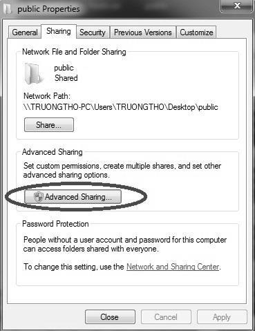
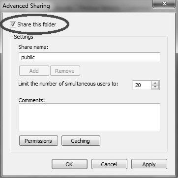
135 2. Sharing Resource Setting Create a sharing folder, and change this folder s setting to offer controller to use, as the below figure. A. Click on advanced sharing B. Click on share this folder C. Click on permission D. Click on add E. Enter GUEST as the new group name, click OK to complete setting 133


136 3. Security setting Right click on folder to share properties security Edit add Guest as a new group, then open group permissions to maximum. 134

137 4. Setting PC name and workgroup Start control panel System change to set Computer Name and Workgroup, and remember these setting contents to use later on when setting controller. 135


138 5. TCP/IP Setting a. Start control panel Network and Internet Network and Sharing Center Properties 136
, select use the following IP address and enter IP address (the forth")
 Network cable (with HUB), select Obtain an IP address")
139 b. Select internet protocol(tcp/ip) as shown below: Jumper cable (without HUB), select use the following IP address and enter IP address (the forth number is different from controller setting) and Subnet mask (same with controller setting) Network cable (with HUB), select Obtain an IP address automatically 137


140 Win 7 OS 1. Sharing resource setting Right-click on folder wants to share, select share with and specific people Share this folder to everyone, and then click Share as follows. Set permission as write/read Left-click on advanced sharing and select share this folder to everyone. 138
141 139

142 Select permission and select full control only read and change 140


143 Open Network and sharing center, select turn off password protected sharing and Open sharing.. 141

144 2. Setting PC name and workgroup Start control panel system and security System "change " to set "Computer Name" and "Workgroup", remember these setting contents to use later on when setting controller. 142
, select use the following IP address and enter IP address(the")
 Network cable(with HUB), select Obtain an IP address")
145 3. TCP/IP Setting Double click Internet Protocol Version 4 (TCP/IPv4) Jumper cable(without HUB), select use the following IP address and enter IP address(the forth number is different from controller setting) and Subnet mask(same with controller setting) Network cable(with HUB), select Obtain an IP address automatically 143
146 3.5 File Transfer This section will show how to transfer files, files transfer is divided into import and export files, allowing controller share files to external devices, such as USB, CF card or users on the network File Import Operation Path: F2-program F8-file manager F4 File import Other interface will appear on screen, press F5- device change to move cursor to desired external device on the status bar Press [Enter] key to access to inside device, if the device icon has red cross, which means that there is no connection to this device, Select the file wants to import and press [Copy] to complete import file Press F4 cancel select to cancel the selected file After complete file transfer, press [Left] or [ESC] to leave this screen 144
147 145

148 3.5.2 File Export Operation Path: F2-program F8-file manager F5 File export Other interface will appear on screen, press F5-device change to move cursor to desired external device on the status bar Press [Enter] key to access to inside device, if the device icon has red cross, which means that there is no connection to this device, Select the file wants to export and press [Copy] to complete export file Press F4 cancel select to cancel the selected file After complete file transfer, press [left] or [ESC] to leave this screen Note: if destination of export file does not exist, below alarm will appear 146
6 Series Mill Controller Operation Manual
 6 Series Mill Controller Operation Manual Date: 2013/10/25 Version: 1.1 Contents 1 Function Key and System Configuration... 4 1.1 Main Screen Sections... 4 1.2 CNC System Configuration... 5 1.3 Coordinate...
IEEM 215. Manufacturing Processes I Introduction to the ARIX CNC milling machine
 IEEM 215. Manufacturing Processes I Introduction to the ARIX CNC milling machine The image below is our ARIX Milling machine. The machine is controlled by the controller. The control panel has several
COPYCAT NEW FANGLED SOLUTIONS 2/6/2009
 1.0 INTRODUCTION 1.1 CopyCat is a unique wizard used with MACH3. It is not a stand alone program. This wizard will allow you to jog a machine around and create a Gcode file from the movement. 2.0 REQUIREMENTS
Conversational Programming for 6000i CNC
 Conversational Programming for 6000i CNC www.anilam.com P/N 634 755-22 - Contents Section 1 - Introduction Section 2 - Conversational Mode Programming Hot Keys Programming Hot Keys... 2-1 Editing Keys...
Lesson 4 Introduction To Programming Words
 Lesson 4 Introduction To Programming Words All CNC words include a letter address and a numerical value. The letter address identifies the word type. The numerical value (number) specifies the value of
Century Star Turning CNC System. Programming Guide
 Century Star Turning CNC System Programming Guide V3.5 April, 2015 Wuhan Huazhong Numerical Control Co., Ltd 2015 Wuhan Huazhong Numerical Control Co., Ltd Preface Preface Organization of documentation
Conversational Programming for 6000M, 5000M CNC
 Conversational Programming for 6000M, 5000M CNC www.anilam.com P/N 70000486F - Contents Section 1 - Introduction Section 2 - Conversational Mode Programming Hot Keys Programming Hot Keys... 2-1 Editing
GSK218M Milling Machine CNC System
 GSK218M Milling Machine CNC System GSK218M is widespread CNC system (matched with machining center and general milling machine) employed with 32-bit high performance CPU and super-large-scale programmable
FAGOR AUTOMATION MC TRAINING MANUAL
 FAGOR AUTOMATION MC TRAINING MANUAL ACER MC TRAINING MANUAL 8 holes 1/2" depth grid pattern R0.125 1.5 6 unit: inch R0.25 4 1.25 2 2.675 1/2" depth rectangular pocket 1/2" depth circular pocket R0.75 8
SYNTEC. Mill Controller Manual (For EZ Series) By: SYNTEC Date: 2010/9/14 Version: 1.0
 By: SYNTEC Date: 2010/9/14 Version: 1.0") SYNTEC Mill Controller Manual (For EZ Series) By: SYNTEC Date: 2010/9/14 Version: 1.0 Contents 1 CNC MILLING CONTROLLER INTERFACE... 1 1.1 CNC System Configuration... 1 1.2 Screen Sections... 2 1.3 Main
SYNTEC Mill Controller Manual (For EZ Series) By: SYNTEC Date: 2010/9/14 Version: 1.0 Contents 1 CNC MILLING CONTROLLER INTERFACE... 1 1.1 CNC System Configuration... 1 1.2 Screen Sections... 2 1.3 Main
CHAPTER 12. CNC Program Codes. Miscellaneous CNC Program Symbols. D - Tool Diameter Offset Number. E - Select Work Coordinate System.
 General CHAPTER 12 CNC Program Codes The next three chapters contain a description of the CNC program codes and parameters supported by the M-Series Control. The M-Series Control has some G codes and parameters
ADVANCED TECHNIQUES APPENDIX A
 A P CONTENTS þ Anilam þ Bridgeport þ Fanuc þ Yasnac þ Haas þ Fadal þ Okuma P E N D I X A ADVANCED TECHNIQUES APPENDIX A - 1 APPENDIX A - 2 ADVANCED TECHNIQUES ANILAM CODES The following is a list of Machinist
Operation Manual (B) KVR-2418 (24L) Fanuc OiMD CNC. KENT INDUSTRIAL (USA) INC Edinger Ave., Tustin, CA 92780
 KVR-2418 (24L) Fanuc OiMD CNC. KENT INDUSTRIAL (USA) INC Edinger Ave., Tustin, CA 92780") Operation Manual (B) KVR-2418 (24L) Fanuc OiMD CNC KENT INDUSTRIAL (USA) INC. 1231 Edinger Ave., Tustin, CA 92780 Tel: (714) 258-8526 Fax: (714) 258-8530 Internet: WWW.KENTUSA.COM KENT USA THE WAY TO AFFORDABLE
Operation Manual (B) KVR-2418 (24L) Fanuc OiMD CNC KENT INDUSTRIAL (USA) INC. 1231 Edinger Ave., Tustin, CA 92780 Tel: (714) 258-8526 Fax: (714) 258-8530 Internet: WWW.KENTUSA.COM KENT USA THE WAY TO AFFORDABLE
Mach4 CNC Controller Mill Programming Guide Version 1.0
 Mach4 CNC Controller Mill Programming Guide Version 1.0 1 Copyright 2014 Newfangled Solutions, Artsoft USA, All Rights Reserved The following are registered trademarks of Microsoft Corporation: Microsoft,
Turning ISO Dialect T
 SINUMERIK 802D Short Guide 09.2001 Edition Turning ISO Dialect T User Documentation SINUMERIK 802D Turning ISO Dialect T Short Guide 09.2001 Edition Valid for Control Software Version SINUMERIK 802D 1
Operation Manual. V3.3 December, Wuhan Huazhong Numerical Control Co., Ltd
 Century Star Milling CNC System Operation Manual V3.3 December, 2007 Wuhan Huazhong Numerical Control Co., Ltd 2007 Wuhan Huazhong Numerical Control Co., Ltd Preface Preface Organization of documentation
Mach4 CNC Controller Mill Programming Guide Version 1.1 Build 3775
 Mach4 CNC Controller Mill Programming Guide Version 1.1 Build 3775 Copyright 2014 Newfangled Solutions, Artsoft USA, All Rights Reserved The following are registered trademarks of Microsoft Corporation:
Operation Manual. 3.1 Absolute coordinate Relative coordinate Mechanical coordinate
 DELTA_NC300_O_EN_20140428 Operation Manual NC300 Table of content Chapter 1: Table of group menu 1.1 Table of system group menu... 1-1 1.2 Primary control panel function keys... 1-9 1.3 Secondary control
G & M Code REFERENCE MANUAL. Specializing in CNC Automation and Motion Control
 REFERENCE MANUAL Specializing in CNC Automation and Motion Control 2 P a g e 11/8/16 R0163 This manual covers definition and use of G & M codes. Formatting Overview: Menus, options, icons, fields, and
MELDAS, MELDASMAGIC, and MELSEC are registered trademarks of Mitsubishi Electric Corporation. The other company names and product names are
 MELDAS, MELDASMAGIC, and MELSEC are registered trademarks of Mitsubishi Electric Corporation. The other company names and product names are trademarks or registered trademarks of the respective companies.
300S READOUTS REFERENCE MANUAL
 300S READOUTS REFERENCE MANUAL 300S Key Layout 1 Display Area 2 Soft keys 3 Power Indicator light 4 Arrow Keys: Use the UP/DOWN keys to adjust the screen contrast. 5 Axis Keys 6 Numeric Keypad 7 ENTER
CIRCULAR INTERPOLATION COMMANDS
 PROGRAMMING JANUARY 2005 CIRCULAR INTERPOLATION COMMANDS G02 CW CIRCULAR INTERPOLATION MOTION & G03 CCW CIRCULAR INTERPOLATION MOTION *X Circular end point X-axis motion *Y Circular end point Y-axis motion
This document shows you how to set the parameters for the ModuleWorks Material Removal Simulation.
 Table of Contents Introduction:... 3 Select Profile:... 4 Tool Table - Create Tool(s)... 5 Tool properties:... 5 Tool Color R/G/B:... 6 Simulation Configurations - create stock... 7 What if plugin is greyed
Polar coordinate interpolation function G12.1
 Polar coordinate interpolation function G12.1 On a Turning Center that is equipped with a rotary axis (C-axis), interpolation between the linear axis X and the rotary axis C is possible by use of the G12.1-function.
Xbox gamepad CNC pendant user manual
 Patrik Tegelberg 2017-09-04 Xbox gamepad CNC pendant user manual Computer controlled manufacturing machines are awesome, and not designed for manual cutting. This controller, for LinuxCNC, maintains the
3000M CNC Programming and Operations Manual for Two-Axis Systems
 3000M CNC Programming and Operations Manual for Two-Axis Systems www.anilam.com P/N 70000496G - Contents Section 1 - CNC Programming Concepts Programs... 1-1 Axis Descriptions... 1-1 X Axis... 1-2 Y Axis...
Software designed to work seamlessly with your CNC Masters machine. Made to work with Windows PC. Works with standard USB
 Software designed to work seamlessly with your CNC Masters machine Made to work with Windows PC Works with standard USB Clutter free interface. The software is engineered for the machine so you don t have
Ultimate Screen Reference Guide
 MACHMOTION Ultimate Screen Reference Guide 8/11/2011 Everything you need to know to use and setup the MachMotion Ultimate Screen. MachMotion Version 1.0.2 2 P a g e Copyright 2011, MachMotion.com All rights
ADT-CNC4940 CNC4940 Milling Machine Control System. Programming Manual
 ADT-CNC4940 CNC4940 Milling Machine Control System Programming Manual Adtech (Shenzhen) Technology Co., Ltd. Add: F/5, Bldg/27-29, Tianxia IC Industrial Park, Yiyuan Rd, Nanshan District, Shenzhen Postal
Mach4 CNC Controller Lathe Programming Guide Version 1.0
 Mach4 CNC Controller Lathe Programming Guide Version 1.0 1 Copyright 2014 Newfangled Solutions, Artsoft USA, All Rights Reserved The following are registered trademarks of Microsoft Corporation: Microsoft,
GE Fanuc Automation. Series 16i / 18i / 21i Model TA Manual Guide. Computer Numerical Control Products. Operator's Manual
 GE Fanuc Automation Computer Numerical Control Products Series 16i / 18i / 21i Model TA Manual Guide Operator's Manual B-63344EN/01 July 1998 Warnings, Cautions, and Notes as Used in this Publication GFL-001
Warranty. Student Workbook for Three-Axis Systems
 www.anilam.com P/N 70000505 - Warranty Warranty ANILAM warrants its products to be free from defects in material and workmanship for one (1) year from date of installation. At our option, we will repair
Our thanks go to: Puppy Linux, RTAI, EMC, axis, all the kernel developers and big mama thornton.
 CoolCNC Linux First Steps This manual is a step by step introduction for the installation of the CoolCNC Linux Live CD. Its intent is to lead to a better understanding of the current processes. This document
PC-BASED NUMERIC CONTROLLER
 Ncstudio PC-BASED NUMERIC CONTROLLER PROGRAMMING MANUAL there is WEIHONG Where there is motion control Thank you for choosing our products! This manual will help you acquaint with our products and learn
Wheel repair and refurbishment application manual
 refurbishment application manual Contents 1. GENERAL DESCRIPTION... 1 2. DIGITIZING... 2 Purpose... 2 Using method... 2 Digitizing operation... 4 Protection or limitations:... 8 Digitizing result checking...
Operation Manual. 3.1 Absolute coordinate Relative coordinate Mechanical coordinate
 DELTA_NC300_O_EN_20130624 Operation Manual Table of content NC300 Chapter 1: Table of group menu 1.1 Table of system group menu... 1-1 1.2 Primary control panel function keys... 1-9 1.3 Secondary control
HAAS AUTOMATION, INC.
 PROGRAMMING WORKBOOK HAAS AUTOMATION, INC. 2800 Sturgis Rd. Oxnard, CA 93030 JUNE 1, 2000 JUNE 2000 PROGRAMMING CONTENTS INTRODUCTION... 1 THE COORDINATE SYSTEM... 2 MACHINE HOME... 5 ABSOLUTE AND INCREMENTAL
Manufacturing Processes with the Aid of CAD/CAM Systems AMEM 405
 AMEM 405 slide 1 Manufacturing Processes with the Aid of CAD/CAM Systems AMEM 405 Dr. Sotiris Omirou AMEM 405 slide 2 CONTENTS 1. CAD/CAM definition 2. Review of Milling Process 3. Know The CNC Machine
CNC Programming Simplified. EZ-Turn Tutorial.
 CNC Programming Simplified EZ-Turn Tutorial www.ezcam.com Copyright Notice This manual describes software that contains published and unpublished works of authorship proprietary to EZCAM Solutions, Inc.
MELDASMAGIC MMI OPERATION MANUAL (FOR L/G) BNP-B2194 (ENG)
 BNP-B2194 (ENG)") MELDASMAGIC MMI OPERATION MANUAL (FOR L/G) BNP-B2194 (ENG) MELDASMAGIC is a registered trademark of Mitsubishi Electric Corporation. Microsoft and Windows are registered trademarks of Microsoft Corporation.
MELDASMAGIC MMI OPERATION MANUAL (FOR L/G) BNP-B2194 (ENG) MELDASMAGIC is a registered trademark of Mitsubishi Electric Corporation. Microsoft and Windows are registered trademarks of Microsoft Corporation.
Lesson 6 The Key Operation Procedures
 Lesson 6 The Key Operation Procedures Step-by-step procedures can keep you from having to memorize every function that you must perform on your CNC machining center. You will soon memorize procedures for
FANUC OPEN CNC OPERATOR S MANUAL BASIC OPERATION PACKAGE 2 B-63924EN/01
 FANUC OPEN CNC BASIC OPERATION PACKAGE 2 OPERATOR S MANUAL B-63924EN/01 No part of this manual may be reproduced in any form. All specifications and designs are subject to change without notice. The export
DIFFERENCES FROM SERIES 0i-C
 B DIFFERENCES FROM SERIES 0i-C Appendix B, "Differences from Series 0i-C", consists of the following sections: B.1 SETTING UNIT...247 B.2 AUTOMATIC TOOL OFFSET...247 B.3 CIRCULAR INTERPOLATION...249 B.4
CNC Knee Type Milling Machines with USA CENTROID M-400S CNC control
 CNC Knee Type Milling Machines with USA CENTROID M-400S CNC control GMM-949-CNC, 9 x49 table, R8, vari-speed, 3 axis CNC... GMM-949F-CNC, 9 x49 table, R8, inverter drive, 5,000 rpm, 3 axis CNC.. Note:
Software Manual. Version: H BENCHTOP ROBOT SOFTWARE USER GUIDE Version H
 Software Manual Version: H6.1.1.292 BENCHTOP ROBOT SOFTWARE USER GUIDE Version H6.1.1.293 Software Manual Table of Contents SECTION 1: INTRODUCTION... 5 1.1 Introduction...6 1.2 Safety...6 1.3 New Features...6
NC CODE REFERENCE MANUAL
 NC CODE REFERENCE MANUAL Thank you very much for purchasing this product. To ensure correct and safe usage with a full understanding of this product's performance, please be sure to read through this manual
ADT-CNC46208 CNC LATHE SYSTEM Maintenance Manual
 ADT-CNC46208 CNC LATHE SYSTEM Maintenance Manual http//www.salecnc.com Email sales@salecnc.com . Contents Contents 1. Foreword... - 3-2. System technical characteristics... - 3-2.1 System structure...-
Conversational Programming for 6000i CNC
 Conversational Programming for 6000i CNC January 2008 Ve 01 634755-21 1/2008 VPS Printed in USA Subject to change without notice www.anilam.com P/N 634755-21 - Warranty Warranty ANILAM warrants its products
3300M/MK CNC Programming and Operations Manual
 3300M/MK CNC Programming and Operations Manual www.anilam.com P/N 70000381C - Contents Section 1 - CNC Programming Concepts Programs... 1-1 Axis Descriptions... 1-1 X Axis... 1-2 Y Axis... 1-2 Z Axis...
EZ-Mill EXPRESS TUTORIAL 2. Release 13.0
 E-Mill EPRESS TUTORIAL 2 Release 13.0 Copyright Notice This manual describes software that contains published and unpublished works of authorship proprietary to ECAM Solutions, Inc. It is made available
CNC MILLING MACHINE NER VC180)
") CNC MILLING MACHINE (SPINNER NER VC180) PREPARED BY: RAFIZAH BINTI ABDUL RASHID NOR ZAIAZMIN BIN YAHAYA PREPARED FOR: ADVANCED MANUFACTURING TECHNOLOGY (EPT 311) Page 1 of 12 TURNING ON THE CNC MILLING
CNC MILLING MACHINE (SPINNER NER VC180) PREPARED BY: RAFIZAH BINTI ABDUL RASHID NOR ZAIAZMIN BIN YAHAYA PREPARED FOR: ADVANCED MANUFACTURING TECHNOLOGY (EPT 311) Page 1 of 12 TURNING ON THE CNC MILLING
SINUMERIK 828D / 840D sl quick reference chart
 SINUMERIK 828D / 840D sl quick reference chart Jog functions 1. Power up with reference procedure (machine-dependent) Initial power up switch the main disconnect switch to on wait for the entire system
Conversational Programming for 6000M, 5000M CNC
 Conversational Programming for 6000M, 5000M CNC www.anilam.com P/N 70000486E - Warranty Warranty ANILAM warrants its products to be free from defects in material and workmanship for one (1) year from date
COMPUTER NUMERICAL CONTROL OF MACHINE TOOLS
 COMPUTER NUMERICAL CONTROL OF MACHINE TOOLS Department of Mechanical Engineering and Aeronautics University of Patras, Greece Dr. Dimitris Mourtzis Associate professor Patras, 2017 1/52 Chapter 8: Two
Section 20: Graphics
 Section 20: Graphics CNC 88HS Graphics Graphics Menu The graphics menu of the page editor has been designed to allow the user to view the part path of the current program in memory. The graphics can be
Microsoft(R) and Windows(R) are either registered trademarks or trademarks of Microsoft Corporation in the United States and/or other countries.
 and Windows(R) are either registered trademarks or trademarks of Microsoft Corporation in the United States and/or other countries.") Microsoft(R) and Windows(R) are either registered trademarks or trademarks of Microsoft Corporation in the United States and/or other countries. MELDAS is a registered trademark of Mitsubishi Electric
Microsoft(R) and Windows(R) are either registered trademarks or trademarks of Microsoft Corporation in the United States and/or other countries. MELDAS is a registered trademark of Mitsubishi Electric
CENTROID. M-SERIES Operator's Manual. Version 8.22 Rev U.S. Patent # Centroid Corp. Howard, PA 16841
 CENTROID M-SERIES Operator's Manual Version 8.22 Rev. 030826 U.S. Patent #6490500 2004 Centroid Corp. Howard, PA 16841 CNC Control Information Sheet Fill out the following and fax back to Centroid Tech
List of Macro Variables
 APPENDIX C List of Macro Variables Variable Purpose Page #0 Null variable 22 #1 #33 Local variables 28 #34 #99 Not available 28 #100 #199 Common variables 28 #200 #499 Not available 28 #500 #999 Permanent
CNC C6/C64/C64T DDB INTERFACE MANUAL
 CNC C6/C64/C64T DDB INTERFACE MANUAL BNP-B2312A(ENG) MELDAS and MELSEC are registered trademarks of Mitsubishi Electric Corporation. The other company names and product names are trademarks or registered
This manual describes the various matters concerning the. operations of this CNC system as much as possible. However, it is
 This manual describes the various matters concerning the operations of this CNC system as much as possible. However, it is impossible to give detailed descriptions to all the unnecessary or unallowable
CNC Programming Simplified. EZ-Turn / TurnMill Tutorial.
 CNC Programming Simplified EZ-Turn / TurnMill Tutorial www.ezcam.com Copyright Notice This manual describes software that contains published and unpublished works of authorship proprietary to EZCAM Solutions,
200D BENCHTOP ROBOT OPERATION MANUAL
 Operation Manual 200D BENCHTOP ROBOT OPERATION MANUAL Table of Contents SECTION 1: INTRODUCTION...5 1. SAFETY PRECAUTIONS...6 2. PACKAGE CONTENTS...7 3. CONNECTOR AND SWITCH LOCATIONS...8 3.1 200D...8
HDS Series Quick Start Guide.
 Techno-Osai Start Up Sequence HDS Series Quick Turn the Main power switch to the ON Position. 220 volts should have been attached to this switch by an electrician. Power On Button. Computer power ON. The
Mach4 Lathe G-Code and M-Code Reference
 Mach4 Lathe G-Code and M-Code Reference Chapter 1: Introduction G-Code is a special programming language that is interpreted by Computer Numerical Control (CNC) machines to create motion and other tasks.
MELDAS is a registered trademark of Mitsubishi Electric Corporation. Other company and product names that appear in this manual are trademarks or
 MELDAS is a registered trademark of Mitsubishi Electric Corporation. Other company and product names that appear in this manual are trademarks or registered trademarks of the respective companies. Introduction
CNC 8055 MC EXAMPLES MANUAL REF Ref. 0601
 EXAMPLES MANUAL Ref. 0601 All rights reserved. No part of this documentation may be copied, transcribed, stored in a data backup system or translated into any language without Fagor Automation's explicit
Ballbar QC20-W - Analysis
 Haas Technical Documentation Ballbar QC20-W - Analysis Applies to machines built from: January, 2016 Scan code to get the latest version of this document Translation Available Ballbar QC20-W - Analysis
SSII SUV MANUAL. LAGUNA TOOLS 2072 Alton Parkway Irvine, California Ph:
 SSII SUV MANUAL LAGUNA TOOLS 2072 Alton Parkway Irvine, California 92606 Ph: 800.234.1976 www.lagunatools.com 2018, Laguna Tools, Inc. LAGUNA and the LAGUNA Logo are the registered trademarks of Laguna
NcStudio Programming Manual
 NcStudio Programming Manual 6th Edition Weihong Electronic Technology Co., Ltd. The copyright of this manual belongs to Weihong Electronic Technology Co., Ltd. (hereinafter referred to as Weihong Company).
GE FANUC 21 CONCEPT 55 MILL ATC TEACHER GUIDE
 GE FANUC 21 CONCEPT 55 MILL ATC TEACHER GUIDE 11/1/07 Version 2 Made by EMCO Authored by Chad Hawk Training Index Control Keyboard Pg 1 Fanuc 21 Control Machine Control Fanuc 21 Screen. Pg 2 Fanuc 21 Keys.
MELDAS is a registered trademark of Mitsubishi Electric Corporation. Other company and product names that appear in this manual are trademarks or
 MELDAS is a registered trademark of Mitsubishi Electric Corporation. Other company and product names that appear in this manual are trademarks or registered trademarks of the respective companies. Introduction
MANUFACTURING PROCESSES
 MANUFACTURING PROCESSES - AMEM 201 Lecture 7: CNC MACHINE TOOLS 1 CNC MACHINE TOOLS TERMINOLOGY NC Numerical Control CNC Computer Numerical Control CAD Computer Aided Design CAM Computer Aided Manufacturing
Welcome to. the workshop on the CNC 8055 MC
 Welcome to the workshop on the CNC 8055 MC Sales Dpt-Training: 2009-sept-25 FAGOR CNC 8055MC seminar 1 Sales Dpt-Training: 2009-sept-25 FAGOR CNC 8055MC seminar 2 This manual is part of the course for
VERTICAL MACHINING CENTER OPERATION MANUAL I-SERIES-CAM
 VERTICAL MACHINING CENTER OPERATION MANUAL I-SERIES-CAM 07.10,2010 FANUC 18M,0I,18I,21I 1. PREFACE... 1-1 2. INSTALLATION AND POWER ON... 2-1 2.1 INPUT POWER ON... 2-2 2.2 SPECIFICATIONS OF ELECTRICAL
Configuring Logosol CNC page 2. Setting up the machine limits and user units page 3. Setting up the Motion parameters page 4. I/O mapping page 7
 Configuring Logosol CNC page 2 Setting up the machine limits and user units page 3 Setting up the Motion parameters page 4 I/O mapping page 7 I/O setup page 9 Tools control page 11 Tool Life management
CNC PART PROGRAMMING
 CNC PART PROGRAMMING (1) Programming fundamentals Machining involves an important aspect of relative movement between cutting tool and workpiece. In machine tools this is accomplished by either moving
Series 0ί -MD Mate CNC STANDARD FEATURES
 STANDARD FEATURES Axis Control Digital Servo Function 1 Controlled Path Simultaneously controlled axes: Up to maximum of 3 Serial Encoder Interface Axis Name Selected from X,Y,Z and U,V,W,A,B,C Spindle
Preface. GSK983Ma User Manual divides into three parts, that is, Programming, Operation and Appendix.
 This user manual describes all proceedings concerning the operations of this CNC system in detail as much as possible. However, it is impractical to give particular descriptions for all unnecessary or
MELDAS is a registered trademark of Mitsubishi Electric Corporation. Other company and product names that appear in this manual are trademarks or
 MELDAS is a registered trademark of Mitsubishi Electric Corporation. Other company and product names that appear in this manual are trademarks or registered trademarks of the respective companies. Introduction
G47 Text Engraving (Group 00) - Mill. Troubleshooting. How it Works. Haas Technical Documentation. Setting 85 is Too High for Shallow Text Engraving
 - Mill. Troubleshooting. How it Works. Haas Technical Documentation. Setting 85 is Too High for Shallow Text Engraving") Haas Technical Documentation G47 Text Engraving (Group 00) - Mill Scan code to get the latest version of this document Translation Available Troubleshooting Setting 85 is Too High for Shallow Text Engraving
Haas Technical Documentation G47 Text Engraving (Group 00) - Mill Scan code to get the latest version of this document Translation Available Troubleshooting Setting 85 is Too High for Shallow Text Engraving
6000i CNC User s Manual
 6000i CNC User s Manual January 2008 Ve 02 627785-21 1/2008 VPS Printed in USA Subject to change without notice www.anilam.com P/N 627785-21 - Warranty Warranty ANILAM warrants its products to be free
OKUMA MACHINING CENTER OPERATORS GUIDE OSP P200M THiNC
 OKUMA MACHINING CENTER OPERATORS GUIDE OSP P200M THiNC OSP P200 Mill Training Rev1 1 OKUMA MACHINING CENTER OPERATORS GUIDE Scope 4 Section 1 Guide to Controls on Operation Panels 5 Section 2 Manual Tool
Chapter 2: Machine Control Panel
 2. MACHINE CNTRL PANEL Chapter 2: Machine Control Panel The most important aspect of correct machine operation is an understanding of the control panel. The following figure shows the layout. [ PWER [~ri
Craftsman CNC. LinuxCNC. Custom developed for Craftsman CNC Routers
 Craftsman CNC LinuxCNC Custom developed for Craftsman CNC Routers Menu File Load gcode Load a gcode program Recent gcode Shows the 10 most recently opened gcode programs Close gcode Closes the current
How to Make a Sign. Eagle Plasma LLC. Accessing the included step by step.dxf files
 Eagle Plasma LLC How to Make a Sign Accessing the included step by step.dxf files The following tutorial is designed to teach beginners, screen by screen, to create a simple sign project. In this lesson
Linear Interpolation and Dwell Cycle. Dr. Belal Gharaibeh
 Linear Interpolation and Dwell Cycle Dr. Belal Gharaibeh 1 Linear Interpolation Linear interpolation is used in part programming to make a straight cutting motion from the start position of the cut to
Introduction. The following documents are available as documents related to the contents of this manual. Refer to these as required.
 Introduction This manual describes the DDB (Direct Data Bus) function used to realize data input/output with a CNC while running a program developed with a EZMotion-NC E60/E68 user PLC (ladder language).
CNC Milling System Operation Manual
 HNC-08M CNC SYSTEM CNC Milling System Operation Manual V1.22 2011/01 WuHan HuaZhong Numerical Control Co., Ltd Table of Contents 1 SUMMARIZE...1 1.1 CNC SOFTWARE SYSTEM INTRODUCTION...1 1.1.1 CNC System
Tutorial 1 Engraved Brass Plate R
 Getting Started With Tutorial 1 Engraved Brass Plate R4-090123 Table of Contents What is V-Carving?... 2 What the software allows you to do... 3 What file formats can be used?... 3 Getting Help... 3 Overview
3000M CNC Programming and Operations Manual for Three- and Four-Axis Systems
 3000M CNC Programming and Operations Manual for Three- and Four-Axis Systems www.anilam.com 70000504H - Warranty Warranty ANILAM warrants its products to be free from defects in material and workmanship
User s Manual V MillPlus IT. NC Software
 User s Manual V600-02 MillPlus IT NC Software 538 952-02 538 953-02 538 954-02 538 955-02 538 956-02 English (en) 6/2008 Controls on the visual display unit Select window User keys Manual operation Axis-direction
Calibration and setup of a tool probe
 Calibration and setup of a tool probe Fundamentals Tool-setting is the process of determining geometric information length, radius and / or diameter of a cutting tool using a tool-setting device. Some
Introduction. Prerequisites. Ballbar - QC20-W - Analysis LAST UPDATED: 12/01/2018
 Ballbar - QC20-W - Analysis LAST UPDATED: 12/01/2018 Ballbar - QC20-W - Analysis Introduction This procedure tells you how to do a Renishaw QC20-W ballbar analysis. The QC20-W BallBar uses a Bluetooth
Content. Content Ⅰ. Introduction of wiring of CNC router...2. Ⅱ.Install control software...2. Ⅲ. Introduction of Software...
 Content Content... 1 Ⅰ. Introduction of wiring of CNC router....2 Ⅱ.Install control software.....2 Ⅲ. Introduction of Software....5 Ⅳ. Description of software menus... 17 Ⅴ. Operation procedures...22 Ⅵ.Attachment:
ACR-MotionMax Programmer's Reference Manual
 ACR-MotionMax Programmer's Reference Manual Programmer's Reference Manual Programming Information - 1 User Information ACR Series products are used to control electrical and mechanical components of motion
Exercise Guide. Published: August MecSoft Corpotation
 VisualCAD Exercise Guide Published: August 2018 MecSoft Corpotation Copyright 1998-2018 VisualCAD 2018 Exercise Guide by Mecsoft Corporation User Notes: Contents 2 Table of Contents About this Guide 4
MASTERCAM DYNAMIC MILLING TUTORIAL. June 2018
 MASTERCAM DYNAMIC MILLING TUTORIAL June 2018 MASTERCAM DYNAMIC MILLING TUTORIAL June 2018 2018 CNC Software, Inc. All rights reserved. Software: Mastercam 2019 Terms of Use Use of this document is subject
StickFont v2.12 User Manual. Copyright 2012 NCPlot Software LLC
 StickFont v2.12 User Manual Copyright 2012 NCPlot Software LLC StickFont Manual Table of Contents Welcome... 1 Registering StickFont... 3 Getting Started... 5 Getting Started... 5 Adding text to your
GE FANUC 21 CONCEPT 55 TURN TEACHER GUIDE
 GE FANUC 21 CONCEPT 55 TURN TEACHER GUIDE 2/13/08 Version 2 Made by EMCO Authored by Chad Hawk Training Index Control Keyboard Pg 1 Fanuc 21 Control Machine Control Fanuc 21 Screen Pg 2 Fanuc 21 Keys Pg
5000M CNC Programming and Operations Manual
 5000M CNC Programming and Operations Manual www.anilam.com P/N 70000508G - Warranty Warranty ANILAM warrants its products to be free from defects in material and workmanship for one (1) year from date