Getting Started Guide RS-EDP & XC167 CPU Module. Version 2 10th June 2010
|
|
|
- Brenda Ford
- 5 years ago
- Views:
Transcription

1 Getting Started Guide RS-EDP & XC167 CPU Module Version 2 10th June 2010 Electrocomponents plc Page 1
2 Contents 1. Introduction 3 2. Development Tool Support FTDI Based USB to JTAG Converter Keil uvision Hitex HiTOP Quick Start Keil uvision Debugging Users Hitex HiTOP for RS-EDP XC Code Size Restrictions Keil uvision and the Keil C Compiler HiTOP for RS-EDP-XC Electrocomponents plc Page 2
3 1. Introduction To get the most out of the RS-EDP platform it s important to understand the concept of the RS-EDP system correctly. This is detailed in the user manuals for the Base Boards. The manual is called RS EDP-BB-SystemBaseBoard User Manual Vx.docx. The base boards come in both 2 position format and 4 position format and share a common user manual. Please read this manual to get an understanding of the system. Each of the CPU Modules (CM or Command module) and Application Modules (AM) has its own user manual, so again these documents must be read to get an understanding on how to use the modules. Each of the boards comes with a selection of software to fully exercise the RS-EDP Application Modules and the peripherals available on the MCU device. In an RS-EDP system there is usually one Command Module (CM) and one or more Applications Modules (AM) plugged in to the Base Board (BB). The XC167 module has been designed as the CPU or Command Module for the system. The Command Module (also referred to as a CPU Module) in a system, dictates whether the whole system is a 3.3V one or a 5.0V one. This CPU module uses a 5.0V microprocessor and so the board is configured as such. If the user is unsure he can check the Vcc_CM signal on the break out connector on the Base Board to determine what voltage the system is. There are 144 pins on the MCU and these are connected via various link options to the Base Board. The Base Board (BB) then provides these signals to the Application Modules thereby allowing the CPU Modules to communicate with the Application Modules. As many of the CPU pins have more than one function it can make the mapping of the connections rather complex so there are additional support documents available to help you with this. The first is the Pin Allocation Spread Sheet. One spread sheet is available for each of the CPU Modules. The one for the NXP family of CPU Modules is called... Pin Allocation pin XC167 Command Module RevXX.xlsx The contents of this spreadsheet are also detailed in the user manual for the XC167 CPU Module. This spreadsheet detailed which pins are mapped to the Base Board backplane and the various link options which need to be configured to connect them accordingly. To get an appreciation of how the Application Modules are mapped to the backplane and how the CPU Module can connect to them, a Mapping Aid exists. The one for the XC167 module is called... Mapping Aid RS-EDP - Complete XC167 Rev.XX.pptx This mapping aid is also present in the User Manual for the CPU Module and at a glance you can see what resources are required to get the best out of each Application Module. The other useful documents you will need are the circuit diagram for the modules you want to connect with each other. These may be contained in the back of the user manual or available to download separately off the EDP web site. So before you start to use the RS-EDP system make sure you have to hand the following documents. The Circuit Diagram of the modules you intend to use (in the user manual) The Base Board User Manual The XC167 CPU Module User Manual The Application Module User Manual The Pin Allocation Spreadsheet The Mapping Aid Electrocomponents plc Page 3
4 In this getting started guide we will go through the process of getting the CPU Module up and running. 2. Development Tool Support 2.1 FTDI Based USB to JTAG Converter On the XC167 CPU Modules is an FTDI chip which has flashed into it a USB to JTAG firmware set. The software allows a host PC to control the XC167 easily, and effectively removes the need for the user to have his own USB debugger. The USB end of this interface is bought down onto the Base Board and onto a mini USB connector. This miniusb effectively allows the user to connect to a host PC and to run a debug session, including programming of the flash, without any additional debugger hardware tools. This means a software suite such as Keil uvision or Hitex HiTOP is all that is required to program and debug code. The pre-programmed FTDI chip is present on all XC167 modules and allows the user to program and enter a debug session via HiTOP IDE. The version of HiTOP required is specifically designed for the RS- EDP platform. It is HiTOP53 for EDP XC167 and is available to download from the RS-EDP website. This software has a code size restriction on it, which allows the user to debug and program files up to this size. Larger files can be programmed but the debug information is lost. HiTOP accesses the XC167 module via the miniusb present on the Base Board. The base board routes the USB D+ and D- signals onto the XC167 CPU Module where the FTDI chip handles the interface to the JTAG connections. When the mini USB lead is present the FTDI chip is active and the XC167 device is under the control of the debugger. When the cable is unplugged, the FTDI chip is disconnected and the XC167 device runs in standalone mode. The FTDI chip also has a spare RS232 virtual communications port on board, in additional to the USB to JTAG interface software. It is therefore possible to route some TTL level RS232 data via this chip therefore eliminating the requirement for a Communications Module, whilst debugging. Refer to the user manual for more information on these. 2.2 Keil uvision The Keil C Compiler for the XC167 is usually bundled together with the Keil uvision IDE. The user would write his code with this tool chain and then download and debug his code via a JTAG interface. Within Keil uvision the user can select a variety of interfaces, which include the standard ULINK Driver for XC167 and Infineon DAS Client for XC167. The first one requires the use of a dongle (ULINK, ULINK2 or ULINK-ME) which interfaces between the Keil uvision IDE and the XC167 CPU module. As the XC167 CPU Module does not come with a ULINK debugger it is suggested to use the second option as detailed below. The standard ULINK tools are bought out onto a 16 way, double row, 0.1 inch pitch connector. This connector will need a reducing socket to interface to the XC167 daughter board. This connector is not provided and the user will need to make his own solution to utilise this interface with an existing ULINK tool. The second solution, Infineon DAS Client for XC167 is designed to interface to the FTDI chip directly. As the board has been designed with the FTDI chip integrated into it, this means Keil uvision can directly connect to the XC167 module. This is done via the mini USB connector on the base board which is routed through the connectors to the XC167 CPU Module.. The settings are shown in the following pictures... Electrocomponents plc Page 4
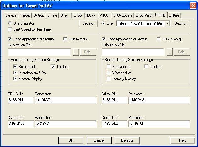

5 Electrocomponents plc Page 5

6 2.3 Hitex HiTOP Hitex s own debugger and IDE combination is called HiTOP. There is a version of this specifically for the XC167 and the RS-EDP system. This is called HiTOP53 for RS-EDP-XC167. This version of HiTOP uses the FTDI chip built into the XC167 CPU module. HiTOP is used extensively as a debugger but not necessarily as a tool to author software. This is because the debug capabilities of the HiTOP system are very good and many customers prefer HiTOP to do the actual debugging on a target device. Also HiTOP has historically supported the larger classical bond out emulation systems that was prevalent to the advent of JTAG debugging. With this in mind, there are lots of existing XC167 customers who have used HiTOP and have familiarity with it. It is possible to author with Keil uvision and to generate a debug file which can then be bought in to HiTOP for debugging. This is done by creating a blank project within HiTOP and pointing to the relevant debug file. To use HiTOP with the RS-EDP system you will need to connect a USB lead from the miniusb connection on the base board to the host PC. The FTDI chip on the base board will handle the JTAG interface to the chip and communication to the host PC. Base board showing mini USB connection Electrocomponents plc Page 6
7 3. Quick Start For the purposes of this quick start guide we will assume a 2 slot Base Board, a DC Motor Drive MC1 Module and an XC167 CPU Module. We will assume the user has downloaded and installed Keil uvision 4.00 or later and has downloaded and installed HiTOP53 for EDP-XC Insert the Motor Drive Module into one of the vacant slots on the base board 2. Insert the CPU Module into the remaining slot on the base board 3. Connect the motor to the Motor Drive module. See user manual for MC1 Module. 4. Connect a 12V DC power supply to the Base Board. Use either the screw in type power terminals or use a wall cube PSU with centre positive and the power in jack. 5. Open Keil uvision and load in the project PID_V3_Noweb for the Xc167 CPU Module. 6. Compile and build the project. The resulting output files should now be available to flash into the MCU and a debugging session can be started. See below. 3.1 Keil uvision Debugging Users 1. Connect the miniusb lead to the base board. 2. Click on the debug icon. The Chip should be erased by the Keil Tool, followed by the flashing of the software and then the loading of the debug file into the debugger. Simply click on run to start the program execution. 3. If all has gone correctly, the program execution should have started. You can then stop the code and single step through it etc. 4. The project you have loaded in will automatically have the options selected for the JTAG over USB. If they are not refer to the section above on Keil for correct settings. 3.2 Hitex HiTOP for RS-EDP XC Connect the miniusb lead to the base board. 2. Start HiTOP for RS-EDP-XC Click on Open Existing Project 4. Open the HiTOP project pid.htp. This is a prebuilt HiTOP project which has some basic scripts included within it. 5. Click on the I want to continue evaluation option. 6. When the download application dialogue box appears, do the following. Make sure the project XC167 tick box is checked; Make sure the enable FLASH programming tick box is checked. Then click on OK. 7. The HiTOP IDE will then program the XC167 device via the FTDI USB to JTAG converter. 8. Once the FLASH has been programmed, click on the Run icon on the tool bar. 9. The debugger will then execute the startup code and break on the first line of the main application. 10. Click the green traffic light go icon to execute the program. 11. If all has gone correctly, you should be able to stop the code and single step through t etc. If you are creating a new HiTOP project from scratch and importing a debug file from Keil uvision, follow the following procedure. 1. Connect the miniusb lead to the base board. 2. Start HiTOP53 for RSEDP-XC Click Create a New Project and then next. 4. Click on the radio button Create an empty project and then next. 5. Enter a project name such as HiTOP_MotorDrivePrj 6. Click on the Browse locate a directory into which you want to locate the HiTOP project. Select the same root directory where the Keil uvision project is located. 7. Click on save and then click Next. 8. In the Tool Selection dialogue, click on RS-EDP-CM-XC167 Electrocomponents plc Page 7

8 9. In the controller selection, click on Infineon and XC167 respectively. 10. In the port selection dialogue ensure the USB interface radio button is selected. Do not enter anything in the serial number box. 11. Leave the start up script blank and press next 12. The project setting box should now appear automatically. 13. In the applications box we need to enter the name of the xc167 file we want to import. There is no visible extension on this file name. This contains all the debug information and symbol names etc that will be used by HiTOP for the debugging session. Click the Applications box and then the new entry box and then use the file browser which pops up to locate the xc167 file. This file is normally located in the root directory where the project is located. 14. Once this has been located, the path and file name should be automatically filled in by HiTOP 15. Uncheck the radio icon Load Applications automatically at start up and tick the Enable automatic detection of modified applications tick box. 16. From the Xc167 tab, select the directories tab and enter the location where the source files are kept. An example is shown below. Electrocomponents plc Page 8
9 17. Now we need to tell HiTOP about the type of FLASH the XC167 MCU has. Within the Project Setting, highlight the flash programming option tab, and a new set of dialogue will appear. Click on Add FLASH icon. 18. In the Add FLASH device dialogue box select, Infineon and the XC 256k Generic option. Fill in the base address of 0x The FLASH programming memory areas should now be visible in the Installed FLASH Devices window. 20. In the RAM Start Address window type in 0xe In the RAM Size window type in 0x Save the HiTOP project before attempting to download the code. This will ensure the project is saved as HiTOP may crash if the settings are not correct. 23. Click on the Debug tab and then select Download. 24. The Download Applications dialogue box will then appear. Ensure the Enable FLASH Download tick box is checked. Click on OK. 25. Click on OK. HiTOP will now automatically load the debug file and flash the MCU with the new code. Whilst you will be able to view the source files in this IDE you will not be able to modify them. To modify the source file you will need to go back to uvision. By changing the source files and then recompiling, HiTOP will now automatically detect a change in the debug image and will ask you to reload it. 26. To RESET the device click on the TR icon button, as this is the target RESET. 27. You can then run and application or single step through the code in the normal debug fashion. 28. HiTOP can be used to write code also, using the GNU Tool Chain, or the Tasking Tool Chain. No examples of this are given here. 4. Code Size Restrictions 4.1 Keil uvision and the Keil C Compiler The Keil tool chain allows you to compile and link code up to 8k bytes. Any more than this and uvision will complain. You can of course upgrade to a full license and several licensing models are available including educational licenses for universities and colleges. Floating licenses and Node locked licenses are available and time limited 12 month licenses also. 4.2 HiTOP for RS-EDP-XC167 The HiTOP debugger is code size restricted to 8k. HiTOP is upgradable from Hitex UK LTD to a full license. For customers that wish to use a Tasking Tool Chain with the RS-EDP it makes sense to upgrade HiTOP to the full version. This is significantly less costly than upgrading Keil uvision. If you have a larger image from Keil uvision than you have the HiTOP licence for, then the image is still loadable into FLASH but the debug information is not available. Most customer will use either Tasking or Keil uvision to author and compile the code, and then use HiTOP to do the actual debugging. Using a blank project and importing the debug files into this is the most popular method of using HiTOP. It is possible to completely author the whole application in HiTOP including editing and compiling but in practice most customers prefer to use their own editor. Electrocomponents plc Page 9
Embedded Development Platform Getting Started Guide for XC167 Command Module
 Embedded Development Platform Getting Started Guide for XC167 Command Module EDP CM XC167 Version 3.11 February 2011 Contents 1. Introduction 3 2. Prepare to run the Hello World Program 4 2.1 Software
Embedded Development Platform
 Embedded Development Platform Getting Started Guide for the ARM mbed Carrier Module EDP-CM-mbed Version 3.11 February 2011 Contents 1. Introduction 3 2. Prepare to run the Hello World Program 4 2.1 Software
Embedded Development Platform Getting Started Guide for Microchip PIM Carrier Module
 Embedded Development Platform Getting Started Guide for Microchip PIM Carrier Module EDP-CM-PIM Version 3.11 February 2011 Contents 1. Introduction 3 2. Prepare to run the Hello World Program 4 2.1 Software
mbed Command Module Adapter Board RS EDP CM mbed User Manual Version 1.02 Electrocomponents plc Page 1
 mbed Command Module Adapter Board RS EDP CM mbed User Manual Version 1.0 Electrocomponents plc Page 1 Contents 1. Introduction. Pin Mapping.1 MCU Pin Allocation.... Backplane Resources Used by the MCU...
XC866 Getting Started on EasyKit & Toolkits
 March 2005 XC866 on EasyKit & Toolkits Page 1 N e v e r s t o p t h i n k i n g. Overview DAvE! This will get you started in using the XC866. KEIL HiTOP XC800_ FLOAD! You will be introduced to the following
Keil TM MDK-ARM Quick Start for. Holtek s HT32 Series Microcontrollers
 Keil TM MDK-ARM Quick Start for Holtek s Microcontrollers Revision: V1.10 Date: August 25, 2011 Table of Contents 1 Introduction... 5 About the Quick Start Guide... 5 About the Keil MDK-ARM... 6 2 System
HandsOn Technology -- HT-MC-02 MODEL: HT-MC-02
 HandsOn Technology 8051 μcontroller Starter Kits FLASH μcontroller PROGRAMMER/DEVELOPMENT SYSTEM MODEL: HT-MC-02 8051 is one of the most popular 8-bit µcontroller architectures in use today, learn it the
Quick Start Guide for the Turbo upsd DK3300-ELCD Development Kit- RIDE
 Contents: Circuit Board upsd DK3300-ELCD Development Board with a upsd3334d-40u6 MCU with Enhanced Graphic LCD RLINK-ST, a USB-based JTAG adapter from Raisonance for debugging with Raisonance Integrate
EDP AM DIO54 Digital IO Module User Manual Version v4.0, 29/03/2010
 EDP AM DIO54 Digital IO Module User Manual Version v4.0, 9/0/00 This document contains information on the DIO54 digital IO module for the RS EDP system. Contents. Digital IO Module. Digital Outputs....
type : Title : 1 / Page : Version : Date : User s guide MNTload TECHNICAL DEPARTMENT User s guide MNTload
 1 / 22 GA v.doc 2 / 22 Updates table ISSUE DATE REVISION DETAILS PREPARED BY 1.0 2005.June.06 Creation L.Hurand/I.lemblin 1.1 2005.June.22 Adding i6280 loading state L.Hurand/I.lemblin 1.2 2007.April.06
LAB #1: The CSM12C32 Module and PBMCUSLK Project Board
 CS/EE 5780/6780 Handout #1 Spring 2007 Myers LAB #1: The CSM12C32 Module and PBMCUSLK Project Board Lab writeup is due to your TA at the beginning of your next scheduled lab. Don t put this off to the
Figure 1. JTAGAVRU1 application The JTAGAVRU1 is supported by AVR Studio. Updated versions of AVR Studio is found on
 JTAG AVR Emulator through USB Main Features AVR Studio Compatible Supports AVR Devices with JTAG Interface Emulates Digital and Analog On-Chip Functions Data and Program Memory Breakpoints Supports Assembler
P89V51RD2 Development Board May 2010
 P89V51RD2 Development Board May 2010 NEX Robotics Pvt. Ltd. 1 P89V51RD2 Development Board Introduction: P89V51RD2 Development Board P89V51RD2 Development Board is a low cost development board which have
Quick-Start Guide. BNS Solutions. QSK62P Plus
 BNS Solutions Quick-Start Guide QSK62P Plus RS-232 Port Link LED 8-character x 2-line LCD Expansion Port (2) Reset Switch Power LED Thermistor I/O Ring (4) M16C MCU Analog Adjust Pot MCU Crystal Expansion
Old Company Name in Catalogs and Other Documents
 To our customers, Old Company Name in Catalogs and Other Documents On April 1 st, 2010, NEC Electronics Corporation merged with Renesas Technology Corporation, and Renesas Electronics Corporation took
Old Company Name in Catalogs and Other Documents
 To our customers, Old Company Name in Catalogs and Other Documents On April 1 st, 2010, NEC Electronics Corporation merged with Renesas Technology Corporation, and Renesas Electronics Corporation took
Evaluation board for NXP LPC2103. User Guide. Preliminary Version updated 27 th Aug TechToys Company All Rights Reserved
 Evaluation board for NXP LPC2103 User Guide 1 SOFTWARE Download from KEIL web site at http://www.keil.com/demo/ for ARM evaluation software. Limitations to this evaluation copy have been summarized on
FIRMWARE UPGRADE GUIDE
 P a g e 1 FIRMWARE UPGRADE GUIDE This guide contains information on how to upgrade, troubleshoot or recover a Nanocom Evolution MK1 and MK2. Before running an upgrade please be aware of the following:
Figure 1. Proper Method of Holding the ToolStick. Figure 2. Improper Method of Holding the ToolStick
 TOOLSTICK UNIVERSITY DAUGHTER CARD USER S GUIDE 1. Handling Recommendations To enable development, the ToolStick Base Adapter and daughter cards are distributed without any protective plastics. To prevent
Tools Basics. Getting Started with Renesas Development Tools R8C/3LX Family
 Getting Started with Renesas Development Tools R8C/3LX Family Description: The purpose of this lab is to allow a user new to the Renesas development environment to quickly come up to speed on the basic
Getting Started with Keil µvision 3 and C51
 Getting Started with Keil µvision 3 and C51 1. Create a Project: Start uvision3. Go to Project->New µvision Project on the µvision3 window. Then enter the name of your project and select a location. Click
Old Company Name in Catalogs and Other Documents
 To our customers, Old Company Name in Catalogs and Other Documents On April 1 st, 2010, NEC Electronics Corporation merged with Renesas Technology Corporation, and Renesas Electronics Corporation took
Getting Started in C Programming with Keil MDK-ARM Version 5
 Getting Started in C Programming with Keil MDK-ARM Version 5 Reason for Revision This document was revised for Keil MDK-ARM v5.14 on February 18, 2015. This document was revised for MSP432 LaunchPad on
CEIBO FE-5111 Development System
 CEIBO FE-5111 Development System Development System for Atmel W&M T89C5111 Microcontrollers FEATURES Emulates Atmel W&M T89C5111 4K Code Memory Real-Time Emulation and Trace Frequency up to 33MHz/5V ISP
Getting Started in C Programming with Keil MDK-ARM Version 5
 Getting Started in C Programming with Keil MDK-ARM Version 5 Reason for Revision This document was revised for Keil MDK-ARM v5.14 on February 18, 2015. This document was revised for MSP432 LaunchPad on
IAR EWARM Quick Start for. Holtek s HT32 Series Microcontrollers
 IAR EWARM Quick Start for Holtek s Microcontrollers Revision: V1.10 Date: August 25, 2011 Table of Contents 1 Introduction... 5 About the Quick Start Guide... 5 About the IAR EWARM... 6 2 System Requirements...
SKP16C26 Tutorial 1 Software Development Process using HEW. Renesas Technology America Inc.
 SKP16C26 Tutorial 1 Software Development Process using HEW Renesas Technology America Inc. 1 Overview The following tutorial is a brief introduction on how to develop and debug programs using HEW (Highperformance
HAND HELD PROGRAMMER QUICK START GUIDE
 HAND HELD PROGRAMMER QUICK START GUIDE IMPORTANT INFORMATION 1) Do not leave the programmer connected to the PC adapter or a target system, as this will drain the battery. Installing Software 1) Run the
Note that FLIP is an Atmel program supplied by Crossware with Atmel s permission.
 INTRODUCTION This manual will guide you through the first steps of getting the SE-8051ICD running with the Crossware 8051 Development Suite and the Atmel Flexible In-System Programming system (FLIP). The
Use of ISP1507-AL Evaluation Boards
 Use of ISP1507-AL Evaluation Boards Application Note AN181103 Introduction Scope This document gives details on hardware and software for using and testing Insight SiP Bluetooth Low Energy module ISP1507-AL,
EB-51 Low-Cost Emulator
 EB-51 Low-Cost Emulator Development Tool for 80C51 Microcontrollers FEATURES Emulates 80C51 Microcontrollers and Derivatives Real-Time Operation up to 40 MHz 3.3V or 5V Voltage Operation Source-Level Debugger
M16C/62P QSK QSK62P Plus Tutorial 1. Software Development Process using HEW4
 M16C/62P QSK QSK62P Plus Tutorial 1 Software Development Process using HEW4 Overview The following tutorial is a brief introduction on how to develop and debug programs using HEW4 (Highperformance Embedded
Megawin 8051 OCD ICE
 Megawin User Manual This document information is the intellectual property of Megawin Technology Co., Ltd. 1 Contents 1 Introduction... 3 Features... 3 Description... 3 2 Hardware Setup... 4 3 Software
Figure 1. Proper Method of Holding the ToolStick. Figure 2. Improper Method of Holding the ToolStick
 TOOLSTICK C8051F560 DAUGHTER CARD USER S GUIDE 1. Handling Recommendations To enable development, the ToolStick Base Adapter and daughter cards are distributed without any protective plastics. To prevent
User Manual. LPC-StickView V3.0. for LPC-Stick (LPC2468) LPC2478-Stick LPC3250-Stick. Contents
 LPC2478-Stick LPC3250-Stick. Contents") User Manual LPC-StickView V3.0 for LPC-Stick (LPC2468) LPC2478-Stick LPC3250-Stick Contents 1 What is the LPC-Stick? 2 2 System Components 2 3 Installation 3 4 Updates 3 5 Starting the LPC-Stick View Software
User Manual LPC-StickView V3.0 for LPC-Stick (LPC2468) LPC2478-Stick LPC3250-Stick Contents 1 What is the LPC-Stick? 2 2 System Components 2 3 Installation 3 4 Updates 3 5 Starting the LPC-Stick View Software
Figure 1-1 ISPAVRU1 application
 ISP AVR Programmer through USB Main Features AVR Studio Interface (AVR Studio 4.12 or later) Supports all AVR Device with ISP interface, refer to AVR Studio Programs both Flash and EEPROM Supports Fuse
Figure 1. Proper Method of Holding the ToolStick. Figure 2. Improper Method of Holding the ToolStick
 TOOLSTICK LIN DAUGHTER CARD USER S GUIDE 1. Handling Recommendations To enable development, the ToolStick Base Adapter and daughter cards are distributed without any protective plastics. To prevent damage
Evaluation Board Getting Started. Toolchain Setup for: TLE9869_EVALKIT TLE986x_EVALB_JLINK TLE9879_EVALKIT TLE987x_EVALB_JLINK
 Evaluation Board Getting Started Toolchain Setup for: TLE9869_EVALKIT TLE986x_EVALB_JLINK TLE9879_EVALKIT TLE987x_EVALB_JLINK Content 1 2 3 4 Evaluation Kit Overview Product Information links Toolchain
NetComm NTC-5000 CallDirect Series HSPA Cellular Routers Quick Start Guide
 NetComm NTC-5000 CallDirect Series HSPA Cellular Routers Quick Start Guide Quick Start Guide Thank you for choosing an industrial HSPA Cellular Router of NetComm s NTC-5000 CallDirect Series. This guide
PSIM Tutorial. How to Use SimCoder with TI F28335 Target Powersim Inc.
 PSIM Tutorial How to Use SimCoder with TI F28335 Target - 1 - Powersim Inc. With the SimCoder Module, PSIM can automatically generate generic code from the control schematic. With SimCoder and the TI F28335
Yun Shield User Manual VERSION: 1.0. Yun Shield User Manual 1 / Version Description Date. 0.1 Initiate 2014-Jun-21
 Yun Shield User Manual VERSION: 1.0 Version Description Date 0.1 Initiate 2014-Jun-21 1.0 Release 2014-Jul-08 Yun Shield User Manual 1 / 22 Index: 1 Introduction... 3 1.1 What is Yun Shield... 3 1.2 Specifications...
EKK-LM3S811 QUICKSTART
 Stellaris LM3S811 Evaluation Kit The Stellaris LM3S811 Evaluation Kit provides a low-cost way to start designing with Stellaris microcontrollers. The LM3S811 Evaluation Board (EVB) can function as either
Contents. Cortex M On-Chip Emulation. Technical Notes V
 _ Technical Notes V9.12.225 Cortex M On-Chip Emulation Contents Contents 1 1 Introduction 2 2 Access Breakpoints 3 3 Trace 5 4 NXP LPC 5 4.1 Boot and Memory Remapping 5 4.2 LPC17xx Startup 5 4.1 LPC11A02/04
USB Debug Adapter. Power USB DEBUG ADAPTER. Silicon Laboratories. Stop. Run. Figure 1. Hardware Setup using a USB Debug Adapter
 C8051F38X DEVELOPMENT KIT USER S GUIDE 1. Kit Contents The C8051F38x Development Kit contains the following items: C8051F380 Target Board C8051Fxxx Development Kit Quick-start Guide Silicon Laboratories
EDP-BB-4A Technical Notes Embedded Development Platform EDP Baseboard EDP-BB-4A User Manual
 Embedded Development Platform EDP Baseboard EDP-BB-4A User Manual Electrocomponents plc Vsn 1.1 Page 1 Contents 1. The EDP System 3 1.1 Introduction... 3 1.1.1 EDP Baseboard... 3 1.1.2 Reusable Components...
Configuring PC Lint for uvision & STM32
 Configuring PC Lint for uvision & STM32 David Giles 2007-11-19 Contents Overview Installing PC Lint Exploring the PC Lint Directory Starting uvision Configuring PC Lint for your project within uvision
78M6613 PSU Firmware Quick Start Guide
 AVAILABLE 78M6613 PSU Firmware Quick Start Guide May 4, 2012 Rev. 0 UG_6613_113 78M6613 PSU Firmware Quick Start Guide UG_6612_113 Maxim cannot assume responsibility for use of any circuitry other than
Data Sheet. LPC-LCD-Board. Contents
 Data Sheet LPC-LCD-Board Contents 1 Scope 2 2 Connections and Controls 3 3 Interfaces 5 4 Jumpers 6 5 Connecting the Board to the LPC-Stick 7 6 Technical Data 8 Rev. 05/2009 003 Windows, Windows XP and
Keil uvision development story (Adapted from (Valvano, 2014a))
)") Introduction uvision has powerful tools for debugging and developing C and Assembly code. For debugging a code, one can either simulate it on the IDE s simulator or execute the code directly on ta Keil
Introduction uvision has powerful tools for debugging and developing C and Assembly code. For debugging a code, one can either simulate it on the IDE s simulator or execute the code directly on ta Keil
ICD Module (P/N ) Instruction Manual
 Instruction Manual") ICD Module (P/N 905501) Instruction Manual 283 Indian River Road Orange, CT 06477 USA Tel 203-799-7875 Fax 203-799-7892 www.diversifiedengineering.net Table of Contents Section Description Page 1 Overview
ICD Module (P/N 905501) Instruction Manual 283 Indian River Road Orange, CT 06477 USA Tel 203-799-7875 Fax 203-799-7892 www.diversifiedengineering.net Table of Contents Section Description Page 1 Overview
Cortex -M3 Hands-On LAB featuring Serial Wire Viewer
 Cortex -M3 Hands-On LAB featuring Serial Wire Viewer RealView MDK Microcontroller Development Kit featuring Keil µvision 3 Luminary Evaluation Board with ULINK2 USB to JTAG Adapter with the Luminary LM3S1968
CoLinkEx_LPC11C14 EVB Kit User Guide
 CoLinkEx_LPC11C14 EVB Kit User Guide Rev. 1.0 Release: 2012-05-07 Website: http://www.coocox.org Forum: http://www.coocox.org/forum/forum.php?id=1 Techinal: master@coocox.com Market: market@coocox.com
TLL5000 Electronic System Design Base Module
 TLL5000 Electronic System Design Base Module The Learning Labs, Inc. Copyright 2007 Manual Revision 2007.12.28 1 Copyright 2007 The Learning Labs, Inc. Copyright Notice The Learning Labs, Inc. ( TLL )
Heterogeneous multi-processing with Linux and the CMSIS-DSP library
 Heterogeneous multi-processing with Linux and the CMSIS-DSP library DS-MDK Tutorial AN290, September 2016, V 1.1 Abstract This Application note shows how to use DS-MDK to debug a typical application running
3-slot Backplane For RC2014 User Guide
 3-slot Backplane For RC204 User Guide For module: SC6 version.0 Design and Documentation by Stephen C Cousins Edition.0.0, 208-0-7 CONTENTS OVERVIEW...2 PRINTED CIRCUIT BOARD... 4 SCHEMATIC... 6 WHAT YOU
DC Motor Drive Module EDP AM MC2 EDP AM MC2 User Manual Version 1.04
 DC Motor Drive Module EDP AM MC2 EDP AM MC2 User Manual Version 1.04 Electrocomponents plc Page 1 Contents 1.0 Introduction 2.0 Command/Slave module EDP AM MC2 As A Command module EDP AM MC2 As A Slave
Windows QuickStart Guide Page 1 of Ambiq Micro, Inc All rights reserved.
 1. Introduction... 2 2. Installing and Using the Ambiq Control Center... 2 2.1 Run the Installer... 3 2.2 A Word about the Apollo EVK Board Stack and It s Integrated Debugger Interface... 7 2.3 Using the
Locktronics PICmicro getting started guide
 Page 2 getting started guide What you need to follow this course 2 Using the built-in programs 3 Create your own programs 4 Using Flowcode - your first program 5 A second program 7 A third program 8 Other
Lab 1 Introduction to Microcontroller
 Lab 1 Introduction to Microcontroller Feb. 2016 1 Objective 1. To be familiar with microcontrollers. 2. Introducing LPC2138 microcontroller. 3. To be familiar with Keil and Proteus software tools. Introduction
Figure 1. Proper Method of Holding the ToolStick. Figure 2. Improper Method of Holding the ToolStick
 TOOLSTICK C8051F330 DAUGHTER CARD USER S GUIDE 1. Handling Recommendations To enable development, the ToolStick Base Adapter and daughter cards are distributed without any protective plastics. To prevent
Instruction Sheet Updating SmartPAC 2 Firmware
 Instruction Sheet Updating SmartPAC 2 Firmware This document shows you how to update SmartPAC 2 firmware, using a USB disk, and load SmartPAC 2 firmware installed on a replacement Compact Flash (CF) card.
Installing LE History Record Reader program software.
 INSTALLATION & OPERATING INSTRUCTIONS FOR THE LE HISTORY RECORD READER These Instructions will inform you on how to install software to use the RS-232/USB Isolator- Adapter and your LE History Record Reader
To install the software please insert the supplied disk or CDROM in your computer and perform the following steps:
 Appendix A Software Installation Instructions Windows 95 To install the software please insert the supplied disk or CDROM in your computer and perform the following steps: Click on your Start button. Select
3 x 25 Watt with E14 socket. Power Class 1 (~100 meters ) Philips LPC2106 ARM7 60 MHz 47 x 23 x 12 cm. About Factorycode
 Philips LPC2106 ARM7 60 MHz 47 x 23 x 12 cm. About Factorycode") Traffic Light Manual Version 1.0 Introduction The traffic light has three separate lights that can be remotely controlled over a serial connection. The serial connection is tunneled through a Bluetooth
Traffic Light Manual Version 1.0 Introduction The traffic light has three separate lights that can be remotely controlled over a serial connection. The serial connection is tunneled through a Bluetooth
HAND HELD PROGRAMMER QUICK START GUIDE
 HAND HELD PROGRAMMER QUICK START GUIDE IMPORTANT INFORMATION 1) Do not leave the programmer connected to the PC adapter or a target system, as this will drain the battery. Installing Software 1) Run the
NetComm Commercial. NetComm NTC-6000 CallDirect Series HSPA Cellular Routers Quick Start Guide
 NetComm Commercial NetComm NTC-6000 CallDirect Series HSPA Cellular Routers Quick Start Guide NetComm Commercial Quick Start Guide Thank you for choosing an industrial HSPA Cellular Router of NetComm s
Getting Started in C Programming with Keil MDK-ARM Version 5
 Getting Started in C Programming with Keil MDK-ARM Version 5 Reason for Revision This document was revised for Keil MDK-ARM v5.14 on February 18, 2015. This document was revised for MSP432 LaunchPad on
NEC 78K0- Family On-Chip Emulation
 _ Technical Notes V9.9.86 NEC 78K0- Family On-Chip Emulation Contents Contents... 1 1 Introduction... 2 2 Emulation options... 3 2.1 Hardware Options... 3 3 CPU Setup... 6 3.1 General Options... 6 3.2
LPCXpresso IDE Power Measurement Guide. Rev June, 2016 User guide
 LPCXpresso IDE Power Measurement Guide User guide 3 June, 2016 Copyright 2013-2016 NXP Semiconductors All rights reserved. ii 1. Power Measurement Overview... 1 2. Quick Start... 2 3. Power Measurement
CMS-8GP32. A Motorola MC68HC908GP32 Microcontroller Board. xiom anufacturing
 CMS-8GP32 A Motorola MC68HC908GP32 Microcontroller Board xiom anufacturing 2000 717 Lingco Dr., Suite 209 Richardson, TX 75081 (972) 994-9676 FAX (972) 994-9170 email: Gary@axman.com web: http://www.axman.com
Job Aid: Replacing the Field Replaceable Units (FRUs) for the Avaya G430 Media Gateway
 for the Avaya G430 Media Gateway") Job Aid: Replacing the Field Replaceable Units (FRUs) for the Avaya G430 Media Gateway! Important: Important: Always check the Avaya Support Website for Product Support Notices at http:// support.avaya.com
Job Aid: Replacing the Field Replaceable Units (FRUs) for the Avaya G430 Media Gateway! Important: Important: Always check the Avaya Support Website for Product Support Notices at http:// support.avaya.com
MCUXpresso IDE LinkServer Power Measurement Guide. Rev November, 2017 User guide
 MCUXpresso IDE LinkServer Power Measurement Guide User guide 14 November, 2017 Copyright 2017 NXP Semiconductors All rights reserved. ii 1. Power Measurement Overview... 1 2. Quick Start... 2 3. Power
HAND HELD PROGRAMMER QUICK START GUIDE
 HAND HELD PROGRAMMER QUICK START GUIDE IMPORTANT INFORMATION 1) Do not leave the programmer connected to the PC, adapters or a target system, as this will drain the battery. Installing Software 1) Run
ZCRMZNICE01ZEMG Crimzon In-Circuit Emulator
 Quick Start Guide QS006602-0408 Introduction Zilog s ZCRMZNICE01ZEMG Crimzon (ICE), shown in Figure 1, provides Crimzon chip family emulation with a Trace and Event system for program debugging using Zilog
USB Debug Adapter. Power USB DEBUG ADAPTER. Silicon Laboratories. Stop. Run. Figure 1. Hardware Setup using a USB Debug Adapter
 C8051F2XX DEVELOPMENT KIT USER S GUIDE 1. Kit Contents The C8051F2xx Development Kits contain the following items: C8051F206 or C8051F226 Target Board C8051Fxxx Development Kit Quick-Start Guide Silicon
W7100A / W7100. Version WIZnet Co., Inc. All Rights Reserved. For more information, visit our website at
 W7100A / W7100 Debugger Guide Version 1.1 2012 WIZnet Co., Inc. All Rights Reserved. For more information, visit our website at http://www.wiznet.co.kr Copyright 2012 WIZnet Co., Inc. All rights reserved.
PSIM Tutorial. How to Use SCI for Real-Time Monitoring in F2833x Target. February Powersim Inc.
 PSIM Tutorial How to Use SCI for Real-Time Monitoring in F2833x Target February 2013-1 - With the SimCoder Module and the F2833x Hardware Target, PSIM can generate ready-to-run codes for DSP boards that
Choosing a Micro for an Embedded System Application
 Choosing a Micro for an Embedded System Application Dr. Manuel Jiménez DSP Slides: Luis Francisco UPRM - Spring 2010 Outline MCU Vs. CPU Vs. DSP Selection Factors Embedded Peripherals Sample Architectures
QuickStart Instructions. Using Keil's ULINK and the Keil ARM/µVision3 Software Development Tool Chain
 phycore -LPC3180 QuickStart Instructions Using Keil's ULINK and the Keil ARM/µVision3 Software Development Tool Chain Note: The PHYTEC Spectrum CD includes the electronic version of the English phycore-lpc3180
Evaluation Board and Kit Getting Started
 Evaluation Board and Kit Getting Started Toolchain Setup for: TLE9879_EVALKIT TLE9869_EVALKIT TLE987x_EVALB_JLINK TLE986x_EVALB_JLINK February 2019 Agenda 1 2 3 4 Evaluation Board and Kit Overview Product
Figure 26 CC Debugger Interface
 Figure 26 CC Debugger Interface Once the CC Debugger is set up with the status indicator LED showing green, you are ready to either read or write a hex file from the board, or to start debugging a project
QUICK START GUIDE TO THE JUMPSTART MICROBOX
 QUICK START GUIDE TO THE JUMPSTART MICROBOX JumpStart MicroBox Contents The JumpStart MicroBox has three hardware components: Nucleo board from ST. This board contains the Cortex M0 STM32F030 microcontroller
CEIBO FE-5131A Development System
 CEIBO FE-5131A Development System Development System for Atmel AT89C5131A Microcontrollers FEATURES Emulates AT89C5131/AT89C5131A with 6/12 Clocks/Cycle 31K Code Memory Software Trace Real-Time Emulation
Nuvoton 4T 8051-based Microcontroller NuTiny-SDK-N78E715 User Manual
 4T 8051 8-bit Microcontroller Nuvoton 4T 8051-based Microcontroller NuTiny-SDK-N78E715 User Manual The information described in this document is the exclusive intellectual property of Nuvoton Technology
NFC NUTSHELL KIT. MCU Modules USER MANUAL REVISION GMMC GmbH Keywords Abstract. Document information
 USER MANUAL REVISION 1.23 Document information Info Keywords Abstract Content User Manual GMMC This document describes how to use of the GMMC s NFC Nutshell KIT and its related tools GMMC GmbH www.gmmc-biz.com
User Manual: LPC1830-Xplorer LPC1830-Xplorer
 LPC1830-Xplorer 1 www.ngxtechnologies.com About NGX Technologies NGX Technologies is a premier supplier of development tools for the ARM7, ARM Cortex M0, M3 and M4 series of microcontrollers. NGX provides
As CCS starts up, a splash screen similar to one shown below will appear.
 APPENDIX A. CODE COMPOSER STUDIO (CCS) v5.1: A BRIEF TUTORIAL FOR THE OMAP-L138 A.1 Introduction Code Composer Studio (CCS) is Texas Instruments integrated development environment (IDE) for developing
CF3000 Dealer Diagnostic Tool Instruction Manual
 CF3000 Dealer Diagnostic Tool Instruction Manual Table of Contents: About the CF3000......3 Important Precautions......4 Components....5 Charging the CF3000......7 Licensing the CF3000.......8 Updating
Getting Started with STK200 Dragon
 Getting Started with STK200 Dragon Introduction This guide is designed to get you up and running with main software and hardware. As you work through it, there could be lots of details you do not understand,
Release Notes for ADSP-CM41x EZ-Kit Lite Board Support Package For Keil MDK
 Release Notes for ADSP-CM41x EZ-Kit Lite Board Support Package 1.0.0 For Keil MDK 2016 Analog Devices, Inc. http://www.analog.com processor.tools.support@analog.com Contents 1 Release Dependencies 4 2
Freescale Semiconductor, Inc.
 Hitex Emulator Target Interface Product Manual Manual Date HITEX Emulator Target Interface Nov 2002 Contents 3 Contents Freescale Semiconductor, Inc. Hitex Target Interface...........................5
8051 General Purpose Board
 8051 General Purpose Board CAMPUS COMPONENT Pvt. Ltd. www.campuscomponent.com 1 DISCLAIMER Information furnished is believed to be accurate and reliable at the time of publication. However, Campus Component
Red Suite 4 Getting Started. Applies to Red Suite 4.22 or greater
 Red Suite 4 Getting Started Applies to Red Suite 4.22 or greater March 26, 2012 Table of Contents 1 ABOUT THIS GUIDE... 3 1.1 WHO SHOULD USE IT... 3 2 RED SUITE 4... 4 2.1 NEW FEATURES IN RED SUITE 4...
Quick Start Guide TWR-S08PT60. 5-Volt S08P Family of 8-bit MCUs for Industrial and Appliance Applications TOWER SYSTEM
 TWR-S08PT60 5-Volt S08P Family of 8-bit MCUs for Industrial and Appliance Applications TOWER SYSTEM Get to Know the TWR-S08PT60 Primary Connector Force BDM Infrared Port Reset Switch Motor Control Daughter
APPENDIX A. CODE COMPOSER STUDIO (CCS) v5: A BRIEF TUTORIAL FOR THE DSK6713
 v5: A BRIEF TUTORIAL FOR THE DSK6713") APPENDIX A. CODE COMPOSER STUDIO (CCS) v5: A BRIEF TUTORIAL FOR THE DSK6713 A.1 Introduction Code Composer Studio (CCS) is Texas Instruments integrated development environment (IDE) for developing routines
APPENDIX A. CODE COMPOSER STUDIO (CCS) v5: A BRIEF TUTORIAL FOR THE DSK6713 A.1 Introduction Code Composer Studio (CCS) is Texas Instruments integrated development environment (IDE) for developing routines
EMUL-PPC-PC. Getting Started Guide. Version 1.0
 EMUL-PPC-PC Getting Started Guide Version 1.0 EMUL PowerPC Getting Started Guide Edition1 ICE Technology. All rights reserved worldwide. Contents Warranty Information European CE Requirements User Responsibility
indart -HC08 In-Circuit Debugger/Programmer for Freescale HC08 Family FLASH Devices User s Manual Rev. 2.0 Copyright 2006 SofTec Microsystems DC01027
 indart -HC08 In-Circuit Debugger/Programmer for Freescale HC08 Family FLASH Devices User s Manual Rev. 2.0 Copyright 2006 SofTec Microsystems DC01027 SofTec Microsystems E-mail (general information): info@softecmicro.com
)8-,768'HY.LW 2YHUYLHZ. )XMLWVX0LNURHOHNWURQLN*PE+ Am Siebenstein Dreieich-Buchschlag, Germany
8-,768'HY.LW 2YHUYLHZ. )XMLWVX0LNURHOHNWURQLN*PE+ Am Siebenstein Dreieich-Buchschlag, Germany") )8-,768'HY.LW 2YHUYLHZ )XMLWVX0LNURHOHNWURQLN*PE+ Am Siebenstein 6-10 63303 Dreieich-Buchschlag, Germany Revision: V1.0 Date: 05.08.1999 Introduction to FUJITSU Development Kit for 16LX CPU family DevKit16
)8-,768'HY.LW 2YHUYLHZ )XMLWVX0LNURHOHNWURQLN*PE+ Am Siebenstein 6-10 63303 Dreieich-Buchschlag, Germany Revision: V1.0 Date: 05.08.1999 Introduction to FUJITSU Development Kit for 16LX CPU family DevKit16
HCS12 BDM Getting Started V4.3
 HCS12 BDM Getting Started V4.3 Background The term BDM stands for Background Debug Mode. It is used for the system development and FLASH programming. A BDM firmware is implemented on the CPU silicon providing
Quick Start Guide for mbed enabling Freescale FRDM-KL25z Freedom board
 Quick Start Guide for mbed enabling Freescale FRDM-KL25z Freedom board FRDM-KL25Z Freedom board is a low-cost evaluation and development platform to demonstrate the capability of the Kinetis-L family of