rev ORGCHART 10 VISIT US ORGCHARTPRO.COM
|
|
|
- Jonas Stewart
- 6 years ago
- Views:
Transcription

1 INTRODUCTION rev ORGCHART 10 VISIT US ORGCHARTPRO.COM
2 INTRODUCTION TABLE OF CONTENTS TABLE OF CONTENTS...2 INTRODUCTION... 5 MOVING ON... 6 QUICK START GUIDE: ORGCHART OVERVIEW... 7 QUICK START GUIDE: BUILDING A CHART IN MINUTES... 8 PART 1: BUILDING A 3D CHART IN 5 MINUTES... 9 PART 2: CUSTOMIZING DATA FIELDS IN 5 MINUTES PART 3: MAKING YOUR CHART LOOK PROFESSIONAL IN 5 MINUTES CHAPTER 1: ORGCHART BASICS WELCOME SCREEN...25 Interface Overview...26 Toolbars and Menus...26 File Tab...26 Top Toolbar...28 Home Tab...28 Grouping Tab...30 Insert Tab...32 Page Layout Tab...33 Data Tab...35 Design Tab...36 View Tab...37 [Home Tab] Zoom Toolbar...37 View Tab...37 Planning Tab...38 [Home Tab] Arrange Toolbar...41 [Home Tab] Font and Alignment Toolbar...42 [Design Tab] Themes Drop Down Menu...42 [Home Tab] Arrange Subordinates Toolbar...43 Arrange Assistants toolbar...45 Outline View Control Bar...46 Docked Menus...47 Chart Design Palette...47 Position Profile (Previously Box Item) menu...48 Data Outline View...48 Moving and resizing toolbars...50 Hiding and revealing toolbars Preparing the work area Zooming in and out Screen Modes Full Screen mode Chart Normal view Master Page View Thumbnail View Data Outline View Division View Security Protecting Your Chart CHAPTER 2: CHART CREATION Arranging chart elements Working with Components Adding Components to a Chart Selecting Components Moving Components Resizing Components Deleting Components Component Cut, Copy and Paste Editing Component Data Changing components Data Fields Connecting components Collapsing Subordinates in Data Outline View Arranging Components Automatically Arranging Parent Components Arranging Subordinate Components Controlling graphics with the Image component.. 77 Divisions Divisions View Shapes Apply Scope Themes Backgrounds Borders AutoTexts Changing the Order of Data Fields ORGCHART 10 VISIT US ORGCHARTPRO.COM
3 INTRODUCTION Customizing the Appearance of Box Components and Connectors...88 Modifying the Fill Style, Border and Shape of a Box Component...88 Using Auto Adjust Size & Word Wrap on Components...92 Paint Format: the Ultimate Component Modifier.93 Box Properties interface...96 Chart Wizard Multiple Charts and Tabbed Browsing Chapter 3: Working with other formats Printing Print Preview Printing Single Page Charts Printing Multiple Page Charts Importing files Import Wizard Import Wizard Importing Excel Importing Databases the Data Link Properties Screen Data Synchronization Importing LDAP Special Considerations Publishing Charts ing a Chart Exporting Charts With the Export Wizard Reports APPENDIX A: INTERFACES Attachments File Attachment Data Menu Attaching Files Border Style Position Detail Menu Box Properties Window Calculated Field Headcount and Team Budget 170 Chart Data Set Chart Design Palette Connector Style Customize Columns (in Data Outline View) Data Link Properties Screen Data Outline View Division View Find Fill Style Font Style Gradient Image Data Menu LDAP Special Considerations Layout Print Pages Link Data Menu Multiple Shapes Calculations Preferred Styles Fast Reports Module (Platinum version only) Interactive PDF Succession Planning Replace Person Function To replace a person: Custom Rules Advanced Import Controls Format Painter / Paintbrush Silent Update Creating Charts from Multiple Files Save Division to a file Delete Division Create Division from file Microsoft Project Import and Export Work Breakdown Structure (WBS) Modeling Data Import Supports Both One and Two Column Hierarchy Methods Name Field Formatting and Recognition Hide Shape Date Fields Support International Date and Time Formats Importing Dotted Line Relationships Hierarchical Data Reports AutoAdjustSize Automatic Box Sizing Options Screen Page Setup Menu Pattern Picture Report Viewer Reports Wizards Importing Tips: ORGCHART 10 VISIT US ORGCHARTPRO.COM
4 INTRODUCTION Additional Features and Functions Setting Up Automation in OrgChart Change Total Headcount to Exclude Manager How to Create a Calculation How to set up a Summary Field Conditional Formatting How to Set up a Condition within the Format Painter Maintaining Divisions in a Chart How to Re-Calculate Divisions in a Chart How to re-create divisions in a chart Renaming and Publishing Divisions Importing Dotted Line Reporting Relationships. 276 Importing Dotted Line Manager Fields Setting Up Dotted Line Reporting in an Existing Chart Changing the Color of a Dotted Line Creating Vertical Groups Vertical Grouping and Using the Staging Area / Orphans Pane Color Coding Your Org Chart Using Markers Color Coding Your Org Chart Using Markers Change Box to Assistant Style Using Markers How to Publish a chart to PDF How to Publish a Section of the chart to PDF Publishing an Org Chart to PowerPoint Adding 9 Boxes in your Org Chart with Smart Fields MS SQL import procedure for OrgChart Professional STEP 1. INTRODUCTORY SCREEN Step 2. Choosing data source type STEP 3. SQL SERVER CONNECTION PARAMETERS. 316 STEP 4. SELECTION OF SOURCE TABLE STEP 5. HIERARCHY BUILDER STEP 6. DATAFIELDS CUSTOMIZATION STEP 7. DIVISION CREATION POLICY Step 8. Ready to go Step 9. Final screen Creating a Preferred Box Style Create a Background Template for your Org Chart Adding a Label/Field to the Boxes in the Chart How to Change Box Shape for the Entire Chart How to Concatenate (Join) Two Fields in the OrgChart How to Maintain Pagination Formatting Resize Boxes Using Format Painter Photos in OrgChart APPENDIX B: GLOSSARY Appendix C: Hot Keys APPENDIX D: CONTACTS Index ORGCHART 10 VISIT US ORGCHARTPRO.COM
5 INTRODUCTION INTRODUCTION Welcome to OrgChart Professional and OrgChart Platinum, the premiere application for all your chart creation needs. With its dynamic and powerful interface, the designing of any chart from the layout of a single department to the hierarchy of an entire corporation is just a few mouse clicks away. This is possible because OrgChart s unique workflow allows complex structures to be organized simply, quickly and efficiently. Whether you prefer dragging and dropping or simply double clicking, changes ranging from the universal to the individual are immediately applied to whatever element you choose. To further increase productivity, the work environment can be customized and rearranged to meet your personal preferences. Never use a menu? Simply hide it. Like a toolbar on the bottom instead of the top? Just re-dock it. Have what you want, when you want, where you want it. To make certain that your charts get the attention they deserve, OrgChart also provides a wide range of themes, backgrounds, borders and unique shapes to make presentations that people don t just have to look at, but ones they want to look at (see below). 5 ORGCHART 10 VISIT US ORGCHARTPRO.COM

6 MOVING ON MOVING ON The following chapters will introduce you to the OrgChart work environment, teach you to master its powerful tools, and ultimately show you how to present your final, polished vision to the world. So, let s get started and make those charts a reality! (Please visit us online at for additional tips, tutorials and the latest events in the OrgChart world.) 6 ORGCHART 10 VISIT US ORGCHARTPRO.COM

7 QUICK START GUIDE: ORGCHART OVERVIEW QUICK START GUIDE: ORGCHART OVERVIEW Let s start with a quick overview of the OrgChart application. Designed with you in mind, it is easy to use and easy to learn. OrgChart lets you quickly build simple or very complex organizational charts. OrgChart also provides a wide range of themes, backgrounds, borders and shapes to make informative, attention-getting presentations. 1. Chart Formatting. The program is organized using Tabs that make it easy to complete a function or task. 2. Chart Design. This area contains drag and drop tools to add boxes and shapes to the chart. 3. Chart Worksheet. This area is where you will build your chart. 4. Position Profile. Any box selected will show its data in this window. 7 ORGCHART 10 VISIT US ORGCHARTPRO.COM

8 QUICK START GUIDE: BUILDING A CHART IN MINUTES QUICK START GUIDE: BUILDING A CHART IN MINUTES Creating eye popping org charts is fun and easy. In this section, we will show you how to build the following chart in three 5-minute tutorials. Note: details on each step and many other incredible functions, options and resources for chart creation are covered in-depth in other parts of this manual. Okay, let s get started! 8 ORGCHART 10 VISIT US ORGCHARTPRO.COM

. 3.")
9 PART 1: BUILDING A 3D CHART IN 5 MINUTES PART 1: BUILDING A 3D CHART IN 5 MINUTES 1. Open a new OrgChart by pressing the File Tab and then the New button. Or select the quick link at the top left corner of the program. A new OrgChart will appear with a single component on screen. 2. Set the Zoom level to 100% by clicking in the View tab and using the Zoom Toolbar and either picking 100% from the drop-down menu or using your mouse scroll wheel (recommended). 3. Go to the Chart Design Palette (on the left side of the screen) and open up the Components area (by clicking on the Components title bar). 9 ORGCHART 10 VISIT US ORGCHARTPRO.COM

. 6.")
10 PART 1: BUILDING A 3D CHART IN 5 MINUTES 4. Scroll down the list of components and choose the component labeled 3 Positions. 5. Holding down the Left mouse button, drag the 3 Positions icon from the Components area and drop it directly onto the on-screen component (an icon will indicate that the component is in the correct position). 6. You will now have a parent component with 3 subordinate components. It will look like this: 10 ORGCHART 10 VISIT US ORGCHARTPRO.COM
11 PART 1: BUILDING A 3D CHART IN 5 MINUTES 7. You now have a basic chart. But plain boxes are pretty boring, so let s jazz things up by giving our components unique shapes for each level. 8. Select the bottom three components by holding down the Left mouse button and dragging an area slightly larger than the components you want to select. When you release the mouse button, the selected components will appear with dotted lines around them. (Note: sometimes they will also appear with either arrows or small boxes on each node as in these illustrations depending if you are in Move or Resize mode.) 9. Open up the Shapes area of the Chart Design Palette by clicking on Shapes. 11 ORGCHART 10 VISIT US ORGCHARTPRO.COM

12 PART 1: BUILDING A 3D CHART IN 5 MINUTES 10. Scroll down and select Folder Shape. Just as you did in Step 4, hold down the Left mouse button, drag the Folder Shape icon from the Shapes area and drop it on to any of three highlighted components. Release the icon. All the selected components will now have folder shapes. 11. Now our chart has distinct shapes for each level, but it still looks flat. We ll give the components a nice three-dimensional feel by creating Drop Shadows. 12. To create Drop Shadows, select all the components by holding down the Left mouse button and dragging an area slightly larger than all the components (see below). 12 ORGCHART 10 VISIT US ORGCHARTPRO.COM
. 15. Choose Drop Shadow. Click in an empty area of the chart to de select the components.")
13 PART 1: BUILDING A 3D CHART IN 5 MINUTES Release the mouse and they will all be selected. 13. With all the components still selected, Right mouse click in an empty area of any of the components. This will launch a pop-up menu. 14. In the pop up menu go to View > Drop Shadow (shown above). 15. Choose Drop Shadow. Click in an empty area of the chart to de select the components. Notice that the drop shadows are present, giving the components a nice three dimensional feel (see below). 13 ORGCHART 10 VISIT US ORGCHARTPRO.COM

14 PART 1: BUILDING A 3D CHART IN 5 MINUTES 16. The basic OrgChart is complete. Now let s save it. To save your chart, go to the File tab and click on Save As. 17. When the Save As menu appears, type in the words OrgChart Tutorial 1 and click ENTER. Congratulations! You have just created an OrgChart in record time! When you are ready, move on to the next 5-minute segment where you will learn how to enter information into the chart you just created. 14 ORGCHART 10 VISIT US ORGCHARTPRO.COM

15 PART 2: CUSTOMIZING DATA FIELDS IN 5 MINUTES PART 2: CUSTOMIZING DATA FIELDS IN 5 MINUTES This lesson uses the chart you created in Part 1. To load that chart, go to File tab and click on Open, choose the file named OrgChart Tutorial 1 and click Open. The chart will appear in the Main Work area. In the previous lesson, you learned how to make a 3D chart with components that were unique on the outside. Now it is time to learn how to make components that are unique on the inside. The different areas inside a component are known as data fields. Data fields can hold many types of information including text, attachments and even images. In this exercise, we are going to customize the Name and Title data fields of our components. Although there are many ways to do this, we will concentrate solely on using the Box Item menu (located by default on the lower left side of the screen, directly below the Chart Design Palette) to make our changes. Box Item pane shows data fields contained in a box record Important: the Box Item menu only becomes active when a component is selected. If no component is selected then it will appear empty with no data fields present. Now that you are familiar with the basic principles of data fields, let s move on to the step by step process of using the Box Item menu to customize the names and titles of each component. 1. Let s start by naming the Parent component. To do this, click on the Parent component (the top one). Notice that the Box Item menu is now active and is displaying the component s data fields. 15 ORGCHART 10 VISIT US ORGCHARTPRO.COM
 and type the new information into the (highlighted) area.")
16 PART 2: CUSTOMIZING DATA FIELDS IN 5 MINUTES 2. To alter a data field, simply double click the field inside the Box Item menu (to make it editable) and type the new information into the (highlighted) area. With the parent still selected, double click inside the Name field in the Box Item menu, type in the word Parent and hit the ENTER key. Box item pane with Parent in name field and Orgchart in title field Hitting ENTER applies the change to the on screen component. It also highlights the next lower data field in the Box Item menu and makes it editable (in this example, the Title field). 3. In the Title field, type in the word OrgChart (see above) and hit ENTER. The title will appear on screen. 4. Repeat Steps 2 & 3 for each subordinate component. To do this, select the subordinate component on the left side and type Child 1 into the Name field and Subordinate into the Title field. Do the same with the other components, typing Child 2 and Child 3 into each respective Name field and Subordinate into the Title fields of both. Type in both the Name and Title fields for each subordinate component BEFORE moving on to the next. Notice that OrgChart remembers the last entry entered into a field (regardless of component) and displays it making re typing the same information unnecessary. When you are done, the chart should look like this: 5. To save this chart, go to the File tab and click on Save As, type in the name OrgChart Tutorial 2 and click Save (also see Part 1, Steps 15 & 16). 16 ORGCHART 10 VISIT US ORGCHARTPRO.COM
17 PART 2: CUSTOMIZING DATA FIELDS IN 5 MINUTES Congratulations! You have now learned the basics of data fields and how to customize the names and titles for each component. The final tutorial in this section will show you how to add colors, titles, designs and more to give your chart a polished, professional look. 17 ORGCHART 10 VISIT US ORGCHARTPRO.COM


18 PART 3: MAKING YOUR CHART LOOK PROFESSIONAL IN 5 MINUTES PART 3: MAKING YOUR CHART LOOK PROFESSIONAL IN 5 MINUTES This lesson uses the chart built in Part 2. To load the chart, go to File > Open, choose the file named OrgChart Tutorial 2 and click Open. The chart will appear in the Main Work area. You now have a fully functional OrgChart. Now let s snazz it up by adding colors, a design, a title and even arranging all the elements in an eye pleasing fashion. 1. First, let s set up our work area so we can see the entire chart. To do this, go to the Zoom Toolbar on the View tab and choose Fit to Window from the drop-down menu, or click in the box and use the mouse scroll wheel. 2. Next, let s automatically resize the components so they fill the page nicely. To do this, simply click the Page Layout tab and click the Fit to Page button. The chart will now appear like this (see below): 3. Now that the basics of our components are set up, it s time to put them on a nice background. Go to the Design tab and select Background. 18 ORGCHART 10 VISIT US ORGCHARTPRO.COM

: 6. Now let s apply some colors.")
19 PART 3: MAKING YOUR CHART LOOK PROFESSIONAL IN 5 MINUTES 4. Scroll down and select Grid. 5. To apply the theme, hold down the Left mouse button, drag the Grid icon from the Backgrounds area and drop it anywhere on the chart. Notice that an attractive grid design now appears behind the components (see below): 6. Now let s apply some colors. There are many ways to add colors to a chart and its components, but the easiest is to simply use a Theme. Themes are color coordinated, professional designs that can be applied by simply dragging and dropping them on to a chart. To apply a theme, go to the Design tab and click on the Theme icon. 19 ORGCHART 10 VISIT US ORGCHARTPRO.COM

: Choosing this will force the theme to be applied to the components in")
20 PART 3: MAKING YOUR CHART LOOK PROFESSIONAL IN 5 MINUTES 7. Important: in default mode, themes do not affect the look or color of the components. To have components adopt a theme s attributes, first select all the components by holding down the Left mouse button and dragging an area slightly larger than all the components, or by clicking Ctrl+A. Once all the components are selected, Right-click over one of them and select Format and then Force Apply Theme (see below): Choosing this will force the theme to be applied to the components in addition to other chart (and workplace) elements. 8. Scroll down and select Lavender. Hold down the Left mouse button, drag the Lavender icon from the Themes. Notice that a color scheme and pattern is applied to the entire chart and all the components (see below): 20 ORGCHART 10 VISIT US ORGCHARTPRO.COM

. 10. To change the name that appears in the Chart Title AutoText element, go to the tab at the bottom of the chart.")
21 PART 3: MAKING YOUR CHART LOOK PROFESSIONAL IN 5 MINUTES Remember, backgrounds and borders can be applied using the same steps. 9. The next step will be to name our chart. To do this, go to the Chart Design Palette and click on the AutoTexts bar. Select Chart Title. To apply, hold down the Left mouse button, drag the Division Title icon from the AutoTexts area and drop it in the center of the chart below the components. (Notice that the default name of Chart 1 appears in the element). 10. To change the name that appears in the Chart Title AutoText element, go to the tab at the bottom of the chart. You can change this by double clicking on the tab and then typing the new name (i.e., OrgChart Professional) 11. Alternately you can click on the Data Outline View at the bottom of the Main Work area, then click on the Divisions View tab (see below). 21 ORGCHART 10 VISIT US ORGCHARTPRO.COM
: 13.")


. b. Click on the Font Style drop down box and choose Bold.")
22 PART 3: MAKING YOUR CHART LOOK PROFESSIONAL IN 5 MINUTES 12. Click on the word Chart 1 and Right mouse click to launch a pop up menu (see below): 13. Type in the words OrgChart Professional and hit Enter or click OK to apply the changes. The new title will appear in the on screen AutoText. 14. The text in the AutoText Chart Title element is too small, so to make it larger, click in the AutoText. A dark box will appear around the text to indicate that it is editable. With the text still selected, go to the Home tab on the Font section and do the following: a. Click on the Font Type drop down box and choose Arial (if this is not already present by default). b. Click on the Font Style drop down box and choose Bold. c. Click on the Font Size drop down box and choose the number 28 (see below). 22 ORGCHART 10 VISIT US ORGCHARTPRO.COM


 18.")
23 PART 3: MAKING YOUR CHART LOOK PROFESSIONAL IN 5 MINUTES 15. The changes will be applied automatically. Your chart will now appear very similar to the following example: 16. We re almost done! All the elements are now present; now we just have to arrange them in an attractive pattern. To do this, we will move the components to the middle of the chart and center the title. 17. Components can only be moved when you are in Move mode. To enter Move mode, go to the Home tab and click the Move mode button (located in the Tools section). (Note: the Move mode button is a toggle switch which turns on and off if selected repeatedly, so you may need to press it twice to get into Move mode.) 18. To move a group of components, click on the group s parent. Green arrows will appear on the parent s nodes to indicate which directions are available for movement. Red X s will indicate directions that are not available (see below). 23 ORGCHART 10 VISIT US ORGCHARTPRO.COM

 and holding down the Left mouse button, drag")

24 PART 3: MAKING YOUR CHART LOOK PROFESSIONAL IN 5 MINUTES 19. Grab the green down arrow on the parent component and while holding down the Left mouse button drag downward to place the entire group in the middle of the chart. 20. To center the title, simply grab the title (the words OrgChart Professional ) and holding down the Left mouse button, drag it to the center of the screen. Your final result should look like this: Congratulations! You have completed your first polished OrgChart! For more detailed information on all of the processes covered in this tutorial, please see the rest of the manual. Additional tips and resources are also available online at ORGCHART 10 VISIT US ORGCHARTPRO.COM
 WELCOME SCREEN When OrgChart Professional loads, the user is greeted with the Welcome Screen.")
25 CHAPTER 1: ORGCHART BASICS CHAPTER 1: ORGCHART BASICS This chapter will introduce you to the OrgChart environment, teach you how to customize the workspace and outline many powerful and diverse chart making tools. (Note: screens may appear slightly different on different systems.) WELCOME SCREEN When OrgChart Professional loads, the user is greeted with the Welcome Screen. This interface is active by default and contains a variety of tools to quickly and efficiently facilitate the chart making process. 25 ORGCHART 10 VISIT US ORGCHARTPRO.COM

26 CHAPTER 1: ORGCHART BASICS INTERFACE OVERVIEW OrgChart s Interface 1. Chart Formatting The program is organized using Tabs that make it easy to complete a function or task. 2. Chart Design contains drag and drop tools to add boxes and shapes to the chart. 3. Box Item any box selected will show its data in this window. 4. Chart Worksheet area where you will build your chart. 5. Data Outline View views of the data behind the org chart. NOTE: this dynamic interface can be customized to match your own creative style. It may also appear different on different hardware configurations and operating systems. Certain buttons and interfaces may also be present or absent and appear in different combinations depending upon your particular version of OrgChart. TOOLBARS AND MENUS All tools are available through the program s ribbon interface. FILE TAB The File tab contains all of the back stage options. 26 ORGCHART 10 VISIT US ORGCHARTPRO.COM

27 CHAPTER 1: ORGCHART BASICS 27 ORGCHART 10 VISIT US ORGCHARTPRO.COM
28 CHAPTER 1: ORGCHART BASICS 1. Info information about the chart properties, author, number of records. 2. New Use this command to create a new chart from a blank sheet or a template. You do not need this command if you are importing data for a chart. 3. Open Opens a chart previously created from the desktop, a network drive, SharePoint, DropBox or OneDrive. 4. Save Saves your chart file in.toc (native chart format) or.ocpt (template) formats. 5. Save As Saves chart with a different name or to other locations, such as SharePoint or Office365 OneDrive. 6. Import Launches the data import wizard. 7. Print Sends chart view to a print device. 8. Print Outline Prints the data outline portion of the chart view 9. Share Sends the native chart file by Publish Launches the publish wizard for outputs such as MS Office, interactive PDF, HTML5, Flash and more. 11. Export Launches the Export wizard, sending chart data to various output formats. 12. Close Closes the current chart file. 13. Account Contains help resources, options and program update functions. 14. Options allows setting of options for startup, checking for updates and more. 15. Exit Quits the program. TOP TOOLBAR These icons in the top left corner of the interface are convenient shortcuts for frequently used commands. The Top Toolbar commands include: 1. New Chart starts a new chart. 2. Save Chart stores the chart for later retrieval. 3. Undo Undoes the previous operation. 4. Redo Redoes the previous operation HOME TAB 28 ORGCHART 10 VISIT US ORGCHARTPRO.COM
 and applies them to another component or group of components. Fantastic for assigning unique formats to positions, divisions and professions. b.")
29 CHAPTER 1: ORGCHART BASICS 1. Clipboard Section a. Format Painter an amazingly powerful tool that takes the visual attributes of a component (size, shape, text fonts, etc.) and applies them to another component or group of components. Fantastic for assigning unique formats to positions, divisions and professions. b. Format Painter Wizard Copies properties of a box to any scope within the chart. This wizard also has an option for using a conditional format using a data value or using a pre chosen rule. c. Copy Image to Clipboard Takes a snapshot of the chart image and copies it to the clipboard for pasting into an of document. 2. Font selection and formatting 3. Alignment a. Font and Size Determines font, color and size. a. Horizontal/Vertical Determines horizontal and vertical text alignment b. Word wrap For any text field, a space in a character string may be used to wrap text and thus reduce box width. c. Show label Shows or hides the name of the field. 4. Box operations 5. Tools a. Properties Shows both the box data format and the box data contents. Box layout is used to show and hide fields. Edit Data may be used to add or change box content. b. Box formatting Enables color of box outline, connectors, shadow and more. a. Move mode allows components to be moved on the chart. It affects components only and is only active when a component is chosen (see Moving Components for details). b. Resize mode allows components to be resized on the chart. It affects components only and is only active when a component is chosen (see Resizing Components for details). 6. Arrangement Styles a. Pick a layout style for the boxes by selecting a supervisor and then one of these layouts. 29 ORGCHART 10 VISIT US ORGCHARTPRO.COM


30 CHAPTER 1: ORGCHART BASICS 7. Edit GROUPING TAB a. Shortcuts to Select and Find The Grouping tab offers ways to break down larger charts into hyperlinked Divisions (also known as sub charts). Other grouping functions let you optimize chart space, to show as many boxes as possible on a given page. 1. Divisions a. Create Division Select any manager with subiordinates. The Create Division command will create a separate hyperlinked chart page. Division boxes have a large arrow in the lower portion of the box. Clicking on this arrow displays the subordinate boxes. b. Dismiss Division Select any Division box. This command will eliminate the hyperlinked chart page, showing all of the subordinate boxes on the same page with the manager. c. Division Wizard Using this wizard you can automatically set division pagination for the entire chart file. d. Save to File Select a box that is a division. This command creates a chart file with only the detail for the selected division. 30 ORGCHART 10 VISIT US ORGCHARTPRO.COM


31 CHAPTER 1: ORGCHART BASICS e. Append File Adds boxes and associated data from another chart file. f. Show Division View Displays the list of Divisions in the lower pane of the application. g. Division Rename Wizard Any data field can be used to name the divisions appearing in the outline view. The result from this wizard shows in the division view and the Division Title autotext field. 2. Box Groups Divisions View a. Co-Managers Group Two boxes can be joined to form a manager group. Without Co-Manager Group With Co-Manager Group b. Vertical Group When looking to show many boxes on a page the vertical Group offers an efficient use of space. 31 ORGCHART 10 VISIT US ORGCHARTPRO.COM


32 CHAPTER 1: ORGCHART BASICS Without Vertical Group With Vertical Group c. Auto Summary Group You can group boxes according to a field such as title. Right-click on the supervisor box ans select Vertical Group / Group by. The field you select automatically determines the grouping of boxes. d. Show Group Counter Only: Another option is to show only the count for the number of records with the same title. INSERT TAB The Insert tab allows you to add boxes, images, text and special connectors to your chart. 32 ORGCHART 10 VISIT US ORGCHARTPRO.COM
 to your chart ba")
.")

33 CHAPTER 1: ORGCHART BASICS 1. Box 2. Images a. Insert a Position box or Team Frame. b. Insert an Assistant box. a. Insert a Picture Adds any supported image type (i.e.,.jpg,.png, gif, etc.) to your chart background. b. Insert a Legend Adds a legend graphic, either from premade Rules of by manual creation. (Note: once a legend is created it cannot be edited. Rather it must be re created from scratch). PAGE LAYOUT TAB Legend Example The Page Layout tab controls how charts are positioned and sized on each page. 1. Page a. Top Margin Sets all pages with a specified top margin. b. Pages Change pages height and width for larger charts. 33 ORGCHART 10 VISIT US ORGCHARTPRO.COM
 and AFTER (right) Fit Chart to Pages applied. b. Size and Position Chart creates an area around the entire chart which allows the chart as a whole to be moved and resized.")

34 CHAPTER 1: ORGCHART BASICS 2. Chart a. Fit chart to pages resizes the components on a chart to fill up as much of the available space as possible (see below). Same chart BEFORE (left) and AFTER (right) Fit Chart to Pages applied. b. Size and Position Chart creates an area around the entire chart which allows the chart as a whole to be moved and resized. (The moveable area appears as a gray box with nodes at the corners see below.) Same chart BEFORE (left) and AFTER (right) Free move and resize mode applied. To move the chart place the mouse cursor in the gray box, hold down the Left Mouse Button and drag to the desired location. To resize the chart place the mouse cursor over one of the nodes, hold down the Left Mouse Button and drag to the desired size. To exit Free Move and Resize mode click the button again to toggle the mode on and off. 34 ORGCHART 10 VISIT US ORGCHARTPRO.COM
35 CHAPTER 1: ORGCHART BASICS DATA TAB The Data tab provides access to the data import and export wizards, as well as the Platinum Markers features and the Compare utility. 1. Import and Configuration 2. Rules 3. Analyze a. Import Perhaps the most powerful feature of OrgChart. This command starts the Import Wizard and allows import of various file types to automatically create the chart. b. Chart Data Set Opens the chart s database. From this dialog you can add fields and calculations, or change the name of any data field. Note: Any changes made in the Chart Data Set impact the entire chart file, nor just a single box. Any field added becomes available to all boxes in the chart file. c. Automation This wizard configures a script for automating the organization chart update and publishing process. The script that is produced from this procedure includes two files; a.bat file and a.ini specifications file. Together these files can be used with Windows Task Scheduler to kick off functions such as data resync and publishing report outputs. d. Resync Data If External data has been changed this option will update the chart database. Only if data has been imported is Resync Data an option. e. Resync Properties Resync Properties are the configuration options for Resync Data. a. Markers and Rules let you color boxes based on data values present in each box. Markers set the possible box colors, and Rules set the data conditions under which the Markers are applied. Markers and Rules work together. You must define a Rule if you want to apply a color Marker to boxes. b. Conditional Formatting a box format style can be configured based upon a rule to instantly respond to a change in data. a. Reports Custom data reports can be created to show any chart data in tabular form. These reports may be printed or output to Excel for additional customization. b. Fast Reports Fast Reports is a special reporting module that creates custom reports and photo directories. 35 ORGCHART 10 VISIT US ORGCHARTPRO.COM

36 CHAPTER 1: ORGCHART BASICS 4. Export 5. Compare c. Dynamic Reports A flexible, interactive report writer that can sort, filter, group and summarize on the fly. Results of the report can be exported to Excel for additional operations or published to PDF. a. Export This command starts the Export Wizard. Any data that is imported, calculated or added manually to the chart can be exported to Excel or a database. b. Export Summary Fields Any hierarchical totals for calculations can be exported. a. Compare Tool This utility will compare any two chart files allowing you to see any and all record and field differences. b. Compare to Active Lets you compare any chart file to the one that is currently open and in view. 6. Track Changes DESIGN TAB a. Track Changes- This enables identification of any fields that change, or records added or records deleted. Results show in a separate pane titles Change Tracking. Current values, prior values and author are included in the tracking. b. PCN Report After any change the Personnel Change Notification document is generated for management approval. c. Accept Changes cumulative changes are itemized in the tracking pane. These changes can be accepted in bulk. d. Reject Changes Or changes can be rejected in bulk. The Design tab offers borders, box templates and backgrounds for your charts. 1. Chart Design a. Themes enables color schemes for your chart boxes and data. b. Backgrounds lets you set color or image backgrounds for a chart page. c. Show Background shows or hides a background previously applied. 36 ORGCHART 10 VISIT US ORGCHARTPRO.COM
37 CHAPTER 1: ORGCHART BASICS 2. Templates 3. Box VIEW TAB a. Apply a Template use a style from another chart file or template file. Note that OrgChart template files have an.ocpt file extension. These template files do not carry any data; they only have style, color and background. a. Preferred Box Styles These box styles include color and data field layouts. b. Add to Preferred Styles This command lets you add any box style you have created to the preferred style library. The View tab controls general visualization of the chart. [HOME TAB] ZOOM TOOLBAR From here, you can control the magnification of the chart area. The Zoom Toolbar commands include: 1. Zoom in increases magnification. 2. Zoom out decreases magnification. 3. Magnification drop down menu lists default magnifications. 4. Background visibility toggles Backgrounds on and off. (Note: the Background Visibility button will only become active after a Background has been applied.) VIEW TAB This tab controls the visual appearance of the work area. The Select View Toolbar commands include: 37 ORGCHART 10 VISIT US ORGCHARTPRO.COM
38 CHAPTER 1: ORGCHART BASICS 1. Views 2. Show 3. Chart 4. Zoom 5. Window PLANNING TAB a. Normal view the default chart creation view (visually simple and uncluttered). b. Print layout view optimized view for printing (with print safe borders, extra tools and the ability to show how a chart is spread across multiple pages). c. Master Page view a powerful mode which allows universal changes to be applied to every page of a multi page chart. It is extremely valuable for creating titles, logos, division names, etc. you wish to repeat on every sheet. This view only reflects universal changes so elements which change from page to page such as individual chart elements and components are hidden in this mode. They reappear once Master Page view has been deactivated. a. Reset Layout returns the program interface to its original layout. This feature is helpful in case you have closed some of the windows and panes and want to have access to them again. b. Designer Show the chart design components on the left side of the screen. c. Profile Preciously named Box Item this window shows the data details for any org chart box selected. d. Report Shows the Dynamic reporting pane for report output. e. Orphans Shows the window that can be used to identify people without supervisors. It also serves as a staging area or parking lot for holding people until you have decided where to place them. a. Levels - If multiple levels of an organization are showing the levels selector can limit the ones that appear a. Window Options Enable presentation of two charts side-by-side. The Planning tab was added to facilitate the use of OrgChart as a planning and modeling tool. As you will notice the commands appearing on this tab are taken from the Data and View tabs. In addition you will see three Open Position Management functions. 38 ORGCHART 10 VISIT US ORGCHARTPRO.COM


39 CHAPTER 1: ORGCHART BASICS Open Position Management in OrgChart enables you to move people from their positions to a staging area, leaving behind an org chart box showing OPEN as the name of the person. Click on Person fields to establish fields that will move with the person. Click on Open Position Settings to determine what is to appear in the position box after it is vacated. Right-click on the person you want to remove (move to the Staging Area). Select command as shown. 39 ORGCHART 10 VISIT US ORGCHARTPRO.COM


40 CHAPTER 1: ORGCHART BASICS Person moves to staging area and leaves behind a box that shows as OPEN. Next you can fill the open position from any person already in the staging area. As shown the new person shows in the open position along with desired fields. Also you will see that the staging area allows for the import of a new file containing candidates for filling open positions. Right-click on the Staging Area panel and select Import Positions. The wizard will guide you through the import of a separate file that can be used to add to people on the chart or fill open positions. 40 ORGCHART 10 VISIT US ORGCHARTPRO.COM
![CHAPTER 1: ORGCHART BASICS [HOME TAB] ARRANGE TOOLBAR The Arrange commands are on the Home tab in the Tools and Style groups. These control how certain Components are arranged on the chart.](/docs-images/72/68050555/images/41-2.jpg "The Arrange Toolbar commands include: 1. Move Sibling Left / Up moves equal subordinates left (or up) the same level. 2.")

41 CHAPTER 1: ORGCHART BASICS [HOME TAB] ARRANGE TOOLBAR The Arrange commands are on the Home tab in the Tools and Style groups. These control how certain Components are arranged on the chart. The Arrange Toolbar commands include: 1. Move Sibling Left / Up moves equal subordinates left (or up) the same level. 2. Move Sibling Right / Down moves equal subordinates right (or down) the same level. 3. Reset positioning this returns a subordinate component back to its previous optimal location after having been repositioned. 4. Reset subordinates positioning this returns the subordinates to their optimal location after having been manually repositioned. The subordinate s parent must be chosen for this button to become active. 5. Auto Arrange shapes this automatically arranges components in a logical order. 6. Sort Select a manager with subordinates. This command will let you sort by up to three fields. 41 ORGCHART 10 VISIT US ORGCHARTPRO.COM
42 CHAPTER 1: ORGCHART BASICS 7. Replace Person When replacing a person deep in a hierarchy this command offers a way to transfer data from one position to another. This function is best used in a position-based org chart for succession planning purposes. [HOME TAB] FONT AND ALIGNMENT TOOLBAR This toolbar controls font and text alignment attributes: The Format Toolbar provides the following font controls: 1. Font type a drop down menu with a list of available alphabets. 2. Font style a drop down menu with choices on letter orientation and weight. 3. Font size a drop down menu for choosing the size of the letters. 4. Font color this launches a palette of pre defined and custom color options. 5. Left align text text starts on the left side and expands to the right. 6. Center align text text starts in the middle spreads evenly to the sides. 7. Right align text text starts on the right and expands to the left. 8. Vertical top align places text at topmost position possible 9. Vertical center align places text at center of field 10. Vertical bottom align places box at bottom of field 11. Word Wrap allows text to wrap where a space in the character string occurs. 12. Show Title shows the field name with a colon before the text. (E.g., Headcount: 32) [DESIGN TAB] THEMES DROP DOWN MENU Clicking on the Theme icon opens up a list of Themes. (These themes can also be found in the Themes area of the Chart Design Palette.) 42 ORGCHART 10 VISIT US ORGCHARTPRO.COM
![CHAPTER 1: ORGCHART BASICS [HOME TAB] ARRANGE SUBORDINATES TOOLBAR Use this menu to automatically arrange Subordinates in a variety of patterns.](/docs-images/72/68050555/images/43-0.jpg "Important: the Parent component must be chosen for the Arrange Subordinates functions to become active. The following arrangement options are available: 1.")

43 CHAPTER 1: ORGCHART BASICS [HOME TAB] ARRANGE SUBORDINATES TOOLBAR Use this menu to automatically arrange Subordinates in a variety of patterns. Important: the Parent component must be chosen for the Arrange Subordinates functions to become active. The following arrangement options are available: 1. Horizontal center align distributes the subordinates equally on each side; creating a very balanced pattern. 2. Horizontal stagger creates a stair step pattern starting with the first subordinate higher, followed a lower component, then followed by another high one. This pattern is repeated with all the subordinates in a chain. 3. Horizontal right align places all the subordinates in a horizontal line to the lower right of the Parent. 4. Horizontal left align places all the subordinates in a horizontal line to the lower left of the Parent. 5. Horizontal Four Columns (Wide Organization) equally distributes the first four subordinates on a horizontal line beneath the Parent. Any additional subordinates will appear in a new row beneath the first, using the Parent as the center. A new row is formed every time the maximum number of four subordinates is reached. Note: this button only becomes active after four subordinates are present. With less than four, the button is grayed out. 6. Horizontal Six Columns (Wide Organization) equally distributes the first six subordinates on a horizontal line beneath the Parent. Any additional subordinates will appear in a new row beneath the first, using the Parent as the center. A new row is formed every time the maximum number of six subordinates is reached. Note: this button only becomes active after four subordinates are present. With less than four, the button is grayed out. 43 ORGCHART 10 VISIT US ORGCHARTPRO.COM

44 CHAPTER 1: ORGCHART BASICS 7. Horizontal Eight Columns (Wide Organization) equally distributes the first eight subordinates on a horizontal line beneath the Parent. 8. Vertical align right places all the subordinates in a vertical line to the lower right of the Parent. 9. Vertical align left places all the subordinates in a vertical line to the lower left of the Parent. 10. Vertical side by side stacks the subordinates side by side beneath each other (very much like stacking crates). It is similar to Align center in that it attempts to create a balanced pattern using the center for alignment. 11. Vertical staff right affects only Staff components and places all staff elements on a vertical line facing to the right of the Parent. 12. Vertical staff left affects only Staff components and places all staff elements on a vertical line facing to the left of the Parent. 13. Vertical Four Columns (Wide Organization) equally distributes the first four subordinates on a horizontal line beneath the Parent. Any additional subordinates will attach vertically to the component above it, moving from left to right, until the maximum number of four components per row is reached. After that number, the process begins again on a new row. Note: this button only becomes active after four subordinates are present. With less than four, the button is grayed out. Vertical hanging connector options You can change the spot where the subordinate connects to the supervisor box to create a more horizontally compact chart. Right-click on the Supervisor box and select Arrange Subordinates / Vertical Arrange Options. Based upon settings you choose these may be the results: 44 ORGCHART 10 VISIT US ORGCHARTPRO.COM
 1.")
45 CHAPTER 1: ORGCHART BASICS ARRANGE ASSISTANTS TOOLBAR This menu is used to automatically arrange Assistants in a variety of professional patterns. (Note: Assistant buttons only become active when more than one Assistant component is attached to the same Parent.) 1. Assistant align right Places all assistant components on a vertical line facing to the right of the Parent. 2. Assistant align left Places all assistant components on a vertical line facing to the left of the Parent. 3. Assistant side by side Stacks the assistant components side by side beneath each other (very much like stacking crates). It is identical to normal Side by side except it only works on Assistant components. 4. Align Assistants horizontal right Stacks the assistant components on the same level and side by side horizontally to the right of the Parent (very much like the links in a chain). 5. Align Assistants horizontal left Stacks the assistant components on the same level and side by side horizontally to the left of the Parent. 6. Align Assistants horizontal side by side Stacks the assistants on the same level and evenly* on either side of the Parent component. 7. Align Assistants vertical right Stacks all of the assistants on top of each other to the right of the Parent (very much like stacking crates, but only on one side). 8. Align Assistants vertical left Stacks all of the assistants on top of each other to the left of the Parent. 45 ORGCHART 10 VISIT US ORGCHARTPRO.COM

46 CHAPTER 1: ORGCHART BASICS 9. Align Assistants vertical side by side Stacks all of the assistants on top of each other evenly on either side of the Parent. Note: Assistants are only stacked evenly if there are an even number of components. If an odd number of assistants are present, then one more assistant will appear on one side of the Parent than on the other. OUTLINE VIEW CONTROL BAR The Outline View Control Bar sits atop the Outline View area and provides a convenient, central location for buttons and menus that are also found in other areas of the program (see below): The Outline View Control Bar contains the following functions (from left to right): 1. Edit Display Options Show hierarchy or not, show column icons or not. 2. Filter Options Outline data view records can be filtered for display scope. 3. Define or Edit Current Data View launches the Edit Data View (Static) menu. By modifying the currently selected data view, this interface determines what data fields appear in the Box Item and Outline View areas. It also determines the order in which these fields are displayed. 4. Print Data Outline Pane launches the standard Windows print interface. This prints the names and values of the data fields currently displayed in the Outline View area. 5. Print Preview Outline launches a preview screen showing how the data fields in the currently displayed Outline View area will appear when printed out. 6. Locate Person displays where a person s component is located. It automatically expands the division which contains the person and centers their component on the screen. 7. Copy takes information from one area and makes it available in another. 46 ORGCHART 10 VISIT US ORGCHARTPRO.COM
47 CHAPTER 1: ORGCHART BASICS 8. Export Wizard launches the Export Wizard which takes the user step-by-step through the process of exporting data fields to various formats and locations. (For more information on exporting data, please see the Export Wizard section of this manual.) 9. Data View Quick Selector this drop-down menu allows for the rapid selection of available data views. This menu performs the same function as the Current Box Layout drop down menu available in the Box Item area. 10. View Options provides a choice of the different display options available in Outline View. DOCKED MENUS Two of OrgChart s most powerful and commonly used menus are the Chart Design Palette and the Box Item menu. By default, both of these are docked on the left side of the screen. (Note: both of these menus can be un docked and dragged almost anywhere in the workspace.) CHART DESIGN PALETTE This is where most of the actual chart creation takes place. The Chart Design Palette contains the following expandable areas: 1. Components the building blocks of a chart. Components can be moved, linked, hidden and resized. By default, they display an entry s Name and Title but can show an almost infinite range of information. 2. Shapes styles that modify a component s shape. IMPORTANT: a shape can only be applied to components that are already present on the chart. 3. AutoTexts boxes which contain the titles of Chart and Division which can be automatically applied to the chart and customized. Note: Information inside an AutoText can only be changed from the Divisions View. To change an AutoText, do the following: a. Place an AutoText on the Chart. b. Open up Divisions View. c. In Division View, highlight the name of the level the AutoText is on. The level will have a default name such as Chart, Division 1, Division 2, etc. d. Press the F2 key to make the default Division name editable or right click to rename. e. Input the text you wish to appear in the AutoText. f. Hit ENTER to apply the change. To expand an area of the Chart Design Palette, click on an area s title bar (In the example below, the Components section has been expanded by clicking its title bar) 47 ORGCHART 10 VISIT US ORGCHARTPRO.COM

 DATA OUTLINE VIEW This area is located at the bottom of the work area.")

48 CHAPTER 1: ORGCHART BASICS POSITION PROFILE (PREVIOUSLY BOX ITEM) MENU Dynamic in nature, this dialog displays the Data Fields for any currently selected component. (Note: the Box Item menu will only become active after an on screen box has been selected.) DATA OUTLINE VIEW This area is located at the bottom of the work area. It allows the centralized management of component information. It can also be used to connect components, assign Supervisors, and change Data Field content. (Note: Data Outline View can only be toggled on and off through the Data View and Divisions View tabs.) Data Outline View can display information in either a list or hierarchy form. 48 ORGCHART 10 VISIT US ORGCHARTPRO.COM
. In the hierarchy view a plus sign (+) means the list can be expanded into a hierarchy.")
49 CHAPTER 1: ORGCHART BASICS Data Outline View with Hierarchy ON Data Outline View with Hierarchy OFF To toggle Hierarchy View on and off go to the View tab and select the leftmost icon. Click on Show Hierarchy. (A check mark will appear next to the title to indicate if the view is on or off). In the hierarchy view a plus sign (+) means the list can be expanded into a hierarchy. A minus sign ( ) means the hierarchy is fully expanded. Clicking inside the box a second time will toggle between views. Each level or component can have its own hierarchy which can be expanded or contracted. The Data Outline View has these additional features: 1. Edit multiple components and their data fields simultaneously Note: for multiple data fields to be edited at once, the data field being edited must be empty in ALL of the chosen components. If any of the selected components has an entry already in that field the process will not work. To edit data fields in multiple components simultaneously, do the following: a. Make certain that there is more than one component on the chart. b. Choose multiple components by holding down the Left mouse button and dragging diagonally across an area just wider than all of the components. c. Examine the Data Outline View. Notice that the data fields for all the chosen components turn blue. d. With all of the components still selected, place the mouse cursor in one of the on screen components. e. Right-click the mouse to bring up a pop up menu of options. f. Choose Properties from the pop up menu. This will launch the Data Properties interface. g. In the Data Properties menu, edit the data field of choice and hit OK (for more details on editing data fields, see the Editing component data section). h. Click OK again to close the Data Properties menu. i. Notice that your new entry appears in all of the components. (Note: the edited data field must be set to visible for each component or the change will not be noticeable on screen.) 49 ORGCHART 10 VISIT US ORGCHARTPRO.COM
50 CHAPTER 1: ORGCHART BASICS 2. Create new data fields with their own unique titles New data field titles can be created through a variety of methods. These new headings such as Name, Company, or any other topic you choose will be displayed along the horizontal title bar in the Data Outline View. For more details on creating new data fields, please see the Changing component data section. (Note: new data field headings will only appear on the Data Outline View title bar after they are set to visible in the Box Item menu. For more information on hiding and revealing data fields, please see the Displaying and hiding a component s data on the chart section.) 3. Arrange the title bar in any order Data field headings (such as Name, Company, etc.) can be arranged in any order along the horizontal title bar in Data Outline View. To change a heading s location, do the following: a. Click on the section of the title bar you want to move (i.e. Name, etc.). b. Holding down the Left Mouse Button, drag the section horizontally across the title bar to a new location. Rearranging by dragging across the title bar A translucent copy of the section being moved will indicate the field s location as it is being moved. The copy will disappear when the mouse is released. c. Release the mouse button. The section will appear in the new location. 4. Resize title bars to resize existing title bars: a. Place the mouse cursor on the divider between one title area and another. It will turn into a two sided arrow (see below): b. Holding down the Left Mouse Button, drag the arrow horizontally across the title bar, making the area either larger or smaller. Notice that the size of the data field changes accordingly. c. Release the arrow. The title bar and the data field are now the new size. MOVING AND RESIZING TOOLBARS MOVING A TOOLBAR Many of the toolbars can be moved from their original locations and placed almost anywhere on the screen. To move a toolbar: 50 ORGCHART 10 VISIT US ORGCHARTPRO.COM
51 CHAPTER 1: ORGCHART BASICS 1. Left click on either: 1) the toolbar s title or 2) the small vertical bar on the toolbar s left side. 2. Holding the Left mouse button, drag the toolbar to the desired position and release. RESIZING A TOOLBAR To change a toolbar s size: 1. Place the mouse cursor over either: 1) one of the toolbar s edges or 2) in the corner of the toolbar. 2. The mouse will change into a Duplex Arrow. 3. Hold down the Left mouse button and drag the toolbar to the desired size. (Note: only the Chart Design Palette, Box Item menu, Data Outline View and Tutorials window can be resized; the small toolbars on the upper tool deck cannot be changed.) HIDING AND REVEALING TOOLBARS Toolbars can be hidden and revealed to un clutter the workspace. In the View tab Show group, a check mark will be present or absent to indicate that the toolbar is visible or hidden. HIDING TOOLBARS To hide a visible toolbar: 1. Go to the View tab, Show group. 2. Click on the name of the toolbar you wish to affect. 3. The toolbar will disappear. REVEALING TOOLBARS To display a hidden toolbar: 1. Go to the View tab, Show group. 2. Click on the name of the toolbar you wish to affect. (Notice that there is no check mark beside the tool s name.) 3. The hidden toolbar will reappear. NOTE: Hidden toolbars will reappear in their previous locations. REVEALING AND HIDING OTHER SECTIONS The Data Outline View, Box Item, Status Bar and Tutorials window are listed on the View menu (not the Toolbars menu). To hide and reveal these areas: 1. Go to the View tab. 51 ORGCHART 10 VISIT US ORGCHARTPRO.COM
52 CHAPTER 1: ORGCHART BASICS 2. Click on Data Outline View, Box Item, or Status Bar. 3. The chosen area will toggle in and out of view accordingly. PREPARING THE WORK AREA MEASURING TOOLS AND GUIDES For precision work, OrgChart provides the following three measuring tools and guides: 6. Rules Rules can be added to the top and left of the work area. To perform this operation, go to the View tab and select Show Rules. 7. Grid To superimpose a grid over a chart, go to the View tab and select Show Grid. (Note: although visible on screen, the grid never appears in the final version of the chart.) 8. Snap to Grid This option forces items to snap to the grid lines and not to the spaces in-between. It is very good for precise alignments. To toggle this option, go to the Home tab and select Snap to Grid in the Tools group. Snap to Grid ZOOMING IN AND OUT Chart magnification can be adjusted in the following two areas: 1. Go to the View tab and select Zoom. 2. The Zoom Toolbar: By default, the work area view is set to Fit to Window. To change this setting: 1. Click the Zoom In button to increase magnification. 2. Click the Zoom Out button to decrease magnification. 3. Open up the Zoom Toolbar s drop down menu and choose from the magnification list. Manually enter a new zoom setting in the Zoom Toolbar. To do this: 4. Click in the Zoom Toolbar s drop down menu. 5. Highlight the numbers in the drop down box by either double clicking on the numbers or placing the cursor to the left or right then holding down the Left mouse button and dragging over the numbers. 6. Type in a new magnification setting. 52 ORGCHART 10 VISIT US ORGCHARTPRO.COM
53 CHAPTER 1: ORGCHART BASICS 7. Left click in the drop down box and roll the mouse scroll wheel to increase or decrease magnification. 8. Roll down to zoom in. 9. Roll up to zoom out. TIP: clicking in the Zoom Toolbar drop down box and using the mouse scroll wheel is the most convenient way to zoom in and out. (Note: to return the chart to its default view, open the Zoom Toolbar s drop down menu and choose Fit to Window.) SCREEN MODES Modes are screen configurations which have unique layouts and toolsets to streamline the chart making process. OrgChart has the following modes: 1. Full Screen 2. Chart Normal View 3. Master Pages View 4. Chart Print Layout View 5. Thumbnail View 6. Data Outline View 7. Divisions View FULL SCREEN MODE This mode maximizes the work area by hiding distracting toolbars and frame elements. ACTIVATING FULL SCREEN MODE There are two methods to activate Full Screen mode: 1. Go to the View tab and select Full Screen in the Windows group. (OR) 2. Press the F11 key to toggle Full Screen mode on and off. RETURNING TO CHART NORMAL MODE There are three ways to return to Chart Normal mode: 1. Go to the View tab and click on Full Screen. (OR) 2. Press the F11 key to toggle Full Screen mode on and off. (OR) 53 ORGCHART 10 VISIT US ORGCHARTPRO.COM
54 CHAPTER 1: ORGCHART BASICS 3. Click the floating Return To Chart Normal box in the work area. CHART NORMAL VIEW This is OrgChart s default configuration. This mode displays the maximum number of tools to optimize all stages of chart creation while simultaneously allowing access to numerous data entry and information retrieval fields. ACTIVATING CHART NORMAL MODE Go to the View tab and click on Normal. MASTER PAGE VIEW Master Page view is a powerful mode which allows universal changes to be applied to every page of a multi page chart. This is extremely valuable for creating titles, graphics, logos, information areas and anything else you wish to repeat on every sheet. In essence, Master Page view is a blank canvas which only reflects the universal changes. Therefore, elements which change from page to page such as individual chart elements and components are hidden in this mode. They reappear once Master Page view has been deactivated. ACTIVATING MASTER PAGE VIEW Two ways to activate the Master Page mode: 1. Go to the View tab and click Master Page. (OR) 2. Right-click on an empty area of the chart. When the supplemental menu appears, click on Master Page. TIPS FOR MASTERING MASTER PAGE VIEW The chart seems to disappear in Master Page view don t worry! It is still there, just hidden. It will reappear once Master Page view is deactivated. Components cannot be placed on the Master Page this occurs because the Master Page will only accept universal (repeating and non changing) elements, whereas OrgChart interprets components as dynamic. Therefore, it will not allow them to be placed in this mode. Elements applied to the Master Page cannot be removed or modified EXCEPT in Master Page view this is done on purpose. By locking these repeating elements in the background, OrgChart allows for the unhampered modification of your chart without having to worry about changing the overall format. Applying a Graphic Using Master Page 54 ORGCHART 10 VISIT US ORGCHARTPRO.COM
 5. The process is complete.")
55 CHAPTER 1: ORGCHART BASICS To apply a graphic using Master Page, do the following: 1. Star with a chart in Normal View. 2. Go to the View tab and click on the Master Page button to switch to Master Page View (notice that the chart from Step 1 is now hidden). 3. Apply a graphic to the Master Page. 4. Close the Master Page by choosing another view (Normal, Print, etc.) 5. The process is complete. Notice that the chart from Step 1 and the graphic from Step 3 are now both visible. IMPORTANT TIP: AutoTexts as well as graphics can be applied in Master Page view. Use AutoTexts for chart titles, division names, dates, or any other text you want to appear on every page of your chart. BONUS TIP: Almost any type of graphic can be applied in Master Page view including photos. If you want to apply a photo and have it appear through a component of the chart, first apply the picture in Master Page view, then return to Normal view, choose the component you want the picture to appear through and set its Transparency to 100% (Format > Fill Style > Color tab). CHART PRINT LAYOUT VIEW This mode is optimized for chart printing. When in this view: 1) dotted printer safe lines will appear in the work area and 2) several grayed out areas of the Print Toolbar will become active. From this mode, you can: 1. Add and delete print pages. 2. Change page orientation between Portrait and Landscape modes. 3. Arrange multiple pages to optimize the printing of oversized charts (charts larger than a single page). 55 ORGCHART 10 VISIT US ORGCHARTPRO.COM
56 CHAPTER 1: ORGCHART BASICS Note: the user must be in Print Layout view for certain print functions to become active. ACTIVATING PRINT LAYOUT VIEW There are two ways to activate Print Layout view: 1. Go to the View tab and click on the Print Layout icon. (OR) 2. Press the Print Layout View button on the View tab. THUMBNAIL VIEW One of the challenges posed by large charts is being able to conveniently navigate while still seeing enough detail to actually find what you are looking for. OrgChart has solved this problem by creating the Thumbnail View. In essence, the Thumbnail View acts as a reverse magnifying glass showing a small version of the entire background chart (which would otherwise be hidden because of the high zoom factor). A red selection rectangle in the thumbnail represents the enlarged area of the chart currently visible in the Main Work space (see below). Thumbnail View in front of zoomed chart in Main Work pane (the red rectangle indicates the magnified area of the chart) IMPORTANT TIP: the selection rectangle in Thumbnail View is most effective when you are zoomed in close enough to see the details of individual components. If you are zoomed out too far, the thumbnail and its selection square is indistinguishable from the zoomed out view of the chart in the main work space. Thumbnail View has two elements: 56 ORGCHART 10 VISIT US ORGCHARTPRO.COM

57 CHAPTER 1: ORGCHART BASICS 1. The Thumbnail pane this displays a small picture of the entire chart. 2. The Selection rectangle this rectangle (red in color) appears inside the thumbnail. It represents the area of the larger background chart which is currently in view. There are two ways to move the rectangle: a. With the mouse place the mouse cursor inside the selection rectangle, hold down the Left mouse button and drag the rectangle to the desired location. A zoomed view of that area will appear on the chart in the main work space. (OR) b. With the chart scroll bars In the main work area, move the vertical and/ or horizontal scroll bars (by either clicking on the bar and dragging, or using the arrow buttons at the extremes of the bar). Notice that the selection rectangle within the Thumbnail View moves as you scroll. To launch Thumbnail View go to View menu and select Show Thumbnail. To close Thumbnail View choose from one of the following options: 1) click the red X in the upper right corner of the Thumbnail View pane or 2) go to the View menu and reselect Show Thumbnail (this will toggle the view off). DATA OUTLINE VIEW Located at the bottom of the work area, the Data Outline View is an area that allows the centralized management of component information in table form. It can also be used to connect components, assign Supervisors, and change Data Field content. To access the Data Outline View (this view is on by default): 1. Go to the View tab and click on the Data Outline View checkbox to toggle the Data View on and off. 2. Choose the Data View tab at the bottom of the Data Outline View area. DIVISION VIEW Division View shares the same window as the Data Outline View but is accessed through a different tab. This view allows you to view and navigate complex charts easily. It does this by displaying the entire chart including all hidden division sub charts in an elegant and simple tree structure. 57 ORGCHART 10 VISIT US ORGCHARTPRO.COM


58 CHAPTER 1: ORGCHART BASICS To access the Divisions View: 1. Go to the View tab and click on the Data and Divisions checkbox to toggle the Data View on and off. 2. Choose the Divisions View tab at the bottom of the Data Outline View area. SECURITY PROTECTING YOUR CHART OrgChart comes with a password security feature which can be applied to individual charts (see below). After a chart s security is set, a prompt will appear requiring the correct password to be entered before the chart will open. 1. To access the Document Security screen go to the Main Menu and click on Tools > Protect Project. 2. To set the password enter an identical password in both the Enter password and Confirm password fields. 3. To access a protected chart enter the correct password when the OrgChart security prompt appears (see below): Important: DO NOT lose your password! Password protected documents cannot be accessed once the password is lost. 58 ORGCHART 10 VISIT US ORGCHARTPRO.COM
59 CHAPTER 1: ORGCHART BASICS To complete this screen, choose one of the following options: 1. OK enters the password. a. If the password is correct the chart will open. b. If the password is incorrect an Incorrect Password notification will be displayed. (Remember, passwords are case sensitive so double check that you are entering your code correctly.) 2. Cancel closes the security prompt without opening the locked chart. 59 ORGCHART 10 VISIT US ORGCHARTPRO.COM
60 CHAPTER 2: CHART CREATION CHAPTER 2: CHART CREATION In this chapter, you will learn how to use OrgChart s many tools to create compelling, informative charts. ARRANGING CHART ELEMENTS All charts are constructed by applying some (or all) of the following seven elements. They can be mixed and matched to create an almost infinite number of unique designs. 1. Themes visual motifs which affect the appearance of the chart, applied components and certain menu views. [Located on the Design tab] 2. Backgrounds patterns which appear only on the chart (but don t affect components). [Located on the Design tab] 3. Borders designs which appear only along the outer edges of the chart. [Located on the Design tab] 4. Shapes styles that modify a component s shape. IMPORTANT: a shape can only be applied to components that are already present on the chart. 5. Components the building blocks of a chart. Components can be moved, linked, hidden and resized. By default, they display an entry s Name and Title but can show an almost infinite range of information. IMPORTANT: people (components) can only be applied through the graphics interface. 6. AutoTexts boxes which contain the titles of Chart and Division which can be automatically applied to the chart and customized. (Note: most of these elements can be accessed several different ways; the most convenient is often through the Chart Design Palette.) 60 ORGCHART 10 VISIT US ORGCHARTPRO.COM
61 CHAPTER 2: CHART CREATION WORKING WITH COMPONENTS Components are the building blocks of a chart. Movable, scalable, linkable and able to contain vast amounts of information, they are the most basic and important element of any project. Components are found in the Components area of the Chart Design Palette. IMPORTANT: People (components) can only be applied through the graphics interface. You cannot add people through the Data Outline view. OPENING THE COMPONENTS AREA 1. Make certain the Chart Design Palette is visible (see Chapter 1: How to hide and reveal toolbars). 2. Place the mouse cursor over the Components bar and Left click the button. TYPES OF COMPONENTS There are ten basic components: 61 ORGCHART 10 VISIT US ORGCHARTPRO.COM
62 CHAPTER 2: CHART CREATION 1. Single element components (only one element appears when the component is dragged on the screen): a. Position the third largest default sized component. This size is the default scale for most of the other components. b. Assistant a unique component designed to be attached and arranged to a Parent. It creates its own space on the main connector and acts independently of any other subordinate components which may be attached. 2. Multiple element components (several components appear as a group when the component is dragged on the screen): a. Multiple launches the Multiple Shapes menu. From there, the number of components and their styles are chosen before being placed on the chart. b. 3 Positions places three standard sized components on the chart. If this is attached as a subordinate, then the three components will be linked when they appear. 3. Unique single components: a. Team Frame a scalable area with an editable title that can frame other components b. Staff a component with an invisible border so only its text information appears on screen. To make a staff visible either: 1) go to the Chart Design Palette, grab a Shape and drop it on the staff, or 2) Right-click the staff and on the pop up menu go to Format > Shape Style. c. Text Block a component designed for text entry. d. Dynamic Connector a configurable connector used to join other components together. e. Image a combined image browser and image editor perfect for finding, modifying and placing graphics onto a chart. It is also perfect for positioning logos (and the like) on multiple chart pages simultaneously by placing them on a chart in Master Page View. ADDING COMPONENTS TO A CHART Components can be placed on the chart in the following ways: 1. From the Components area Hold down the Left mouse button and drag a component on to the chart. 2. From the Main Menu Go to the Insert tab and click on Position 3. Use the hotkeys Alt+A. SELECTING COMPONENTS Once components have been placed on the chart they can be selected individually or in groups. 1. To select an individual component, you can do any of the following: a. Click on the component with the mouse. 62 ORGCHART 10 VISIT US ORGCHARTPRO.COM
63 CHAPTER 2: CHART CREATION b. Hold down the Left mouse button and drag diagonally across an area just wider than the component. c. Go to Data Outline View and click on the component s name. 2. To select multiple components at once: a. Hold down the Left mouse button and drag diagonally across an area just wider than all of the components. IMPORTANT: when multiple components are selected, all changes (new shapes, formatting, etc.) will be applied to all of the components. MOVING COMPONENTS To move a component, do the following: 1. Enter Move mode Important: Components can only be moved when Move mode is active. To enter Move mode: a. Go to the Home tab and click this button to toggle between the Move and Resize modes and back again. b. Left click the Move Mode button on the Home tab Tools section: 2. Select component To select a component do the following: a. Left click on the component with the mouse. b. Hold down the Left mouse button and drag diagonally across an area just wider than the component. c. Go to Data Outline View and click on the component s name. 3. Green arrows will appear on certain nodes to signify the component is ready to be moved (see below). Can move in ALL directions Can move in ONE direction Note: green arrows will only appear in the directions the component can be moved. Red X marks will appear in all directions that are not available. 4. Left mouse click on any of the available arrows (nodes) to grab it. 63 ORGCHART 10 VISIT US ORGCHARTPRO.COM
64 CHAPTER 2: CHART CREATION 5. Hold down the Left mouse button and drag the component in any of the available directions. Important: Although many components can be moved at once, only one component can be highlighted at a time for movement. To move several components at once, highlight the highest component in the hierarchy (the uppermost parent) and move it. The rest of the subordinate components will move along with the parent (as a group). RESIZING COMPONENTS To resize components, do the following: 1. Enter Resize mode Important: Components can only be resized when Resize mode is active. To enter Resize mode: a. Go to the Home tab Tools group and click on the Resize mode option. 2. Select component(s) Components can be selected individually or in groups. There are three ways to select components: a. Left click on the component with the mouse. b. Hold down the Left mouse button and drag diagonally across an area just wider than the component. This technique also works for selecting multiple components. c. Go to Data Outline View and click on the component s name. 3. Blue boxes will appear on each of the component s nodes to signify it is ready to be resized (see below). Component in Resize Mode 4. Left mouse click to grab one of the nodes. 5. Hold down the Left mouse button and drag in or out to resize the component. DELETING COMPONENTS To delete a component from the chart: 1. Highlight the component. 2. Press the Delete key. 64 ORGCHART 10 VISIT US ORGCHARTPRO.COM
. 2.")
65 CHAPTER 2: CHART CREATION COMPONENT CUT, COPY AND PASTE Components can be cut, copied and pasted. Each of these performs the following function: 1. Cut: this deletes the selected component from the screen and places it on the Windows Clipboard (in memory where it can be retrieved later and placed elsewhere). 2. Copy: the selected component remains on screen and a copy of it is placed on the Windows Clipboard. 3. Paste: this puts the (previously cut or copied) component from the Windows Clipboard on to the work area. CONNECTING COMPONENTS THROUGH CUT, COPY AND PASTE Components can be connected by cutting, copying and pasting. These commands can be accessed in as follows: 1. Go to the Home tab Clipboard group. Cut, copy and paste are all located here. 2. Make certain two (unconnected) components are on the chart. 3. Cut or copy a component (we will call this Component #1). 4. Highlight the second component (we will call this Component #2). 5. With Component #2 still highlighted, paste Component #1 from the clipboard. 6. When Component #1 appears, it will be connected to Component #2. EDITING COMPONENT DATA On screen graphics are just a small part of what components can do. Components can also contain vast amounts of information which can be entered, edited, exported and even printed out. A component s information is displayed in Data Fields. These Data Fields appear in the following areas: 1. The Position Profile (Box Item) menu. 2. The Data Outline View area. 3. The Data Properties box. DISPLAYING A COMPONENT S DATA IN THE DATA FIELDS Click on a component to display its data. (Note: the Box Item menu and the Data Outline View will remain empty until at least one component is selected.) 65 ORGCHART 10 VISIT US ORGCHARTPRO.COM

66 CHAPTER 2: CHART CREATION DISPLAYING AND HIDING A COMPONENT S DATA ON THE CHART A component can have dozens of Data Fields far too many to be displayed on the chart. To solve this, the user can control which fields are visible. By default, the Name and Title fields are active. To select which fields will be displayed: 1. Click on the desired component/box. 2. Right click and select Properties. (or you can press Alt Enter) 3. Go to the Define Layout tab in the Box Properties dialog. 4. Drag a field from the left field list to the box preview in order to display it in a chart box. ACCESSING INDIVIDUAL DATA FIELDS There are four ways to access a component s data fields: 1. Position Profile (Box Item): single click in the box next to the field s name. 2. Data Outline View: double click in the field of choice. 3. On screen Component (method 1): double click in an empty area in the component. This will launch a new Box Properties window. Once the window appears, single click in a field for data entry. 4. On screen Component (method 2): Right-click in an empty area of the component. This will launch an additional menu. Go to the bottom of the menu and choose Properties. This will launch the Box Properties interface. Click on a data field and edit as normal. DATA FIELDS INFORMATION TYPES Information fields may be of the following types: 1. Text text information can be typed directly (or cut and pasted) into these fields. 66 ORGCHART 10 VISIT US ORGCHARTPRO.COM
67 CHAPTER 2: CHART CREATION 2. Link double clicking this field launches a new interface for link creation. 3. Image stored images are linked to a component through this field (see Appendix B). 4. Attachment stored information files are linked to a component through this field (see Appendix B). 5. Numeric Numbers with or without decimals. 6. Date/Time Various date formats 7. Currency Most international currencies are available. 8. Enumeration Develops a dropdown list of specific data choices 9. Query Enables a search using predefined rules. 10. Calculated Count and Sum for headcount, span of control, budget summaries, levels and more. 11. Name 26 permutations of a name can be accommodated. 12. Smart field Sets a graphical or text indicator on a box based upon a rule. 13. Concatenation Let s you connect two data fields such as first and last names. 14. Time Span Calculates the number of days between two dates. 15. Formula Use any two numeric fields in a computation to generate a third. CHANGING COMPONENTS DATA FIELDS Data Field customization takes place in the following areas: 1. Global changes to ALL the data fields are made on the Default Fields Set menu (for more details, please see the Default Fields Set section). 2. Changes to a single component s data fields are made on the Data Properties menu (for more details, please see the Data Properties section). CONNECTING COMPONENTS Charts are created by taking independent components and linking them together in a logical order (or hierarchy). There are five ways to link components together: 1. Drag and drop one box directly on top of another. 2. Use a Dynamic Connector to link two elements together. 3. Paste a previously cut or copied component on a highlighted element. 4. In the Box Item menu, click on the Supervisor field and choose from the list. 5. In the Data Outline View, click on the name of a component and drop it over the name of another component in the table. CONNECTING BY DRAGGING AND DROPPING 67 ORGCHART 10 VISIT US ORGCHARTPRO.COM
68 CHAPTER 2: CHART CREATION Most commonly you will use this method to connect boxes in the OrgChart. 1. Select an on-screen box component by clicking on it. 2. With the original box component still highlighted, go to Chart Design palette > Components. 3. Left mouse click on a new component. 4. Still holding down the Left mouse button, drag the new component over the (still highlighted) on screen component you wish to connect to. 5. Small icon boxes will appear indicating when the new component is in the correct position to link either to the left, center or right of the original on screen component (see below). LEFT CENTER RIGHT 6. When the icon indicates the direction you wish to place the new component, release the left mouse button and drop it on the (still highlighted) on screen component. 7. Notice that the new component appears to jump off the original element and that the two are now connected. CONNECTING COMPONENTS WITH A DYNAMIC CONNECTOR A dynamic connector is unique because it does not show up in the database. It is graphical only. Use the dynamic connector when you want to show a person who reports to more than one supervisor. 1. Make certain two (unconnected) components are on the chart. 2. Go to Chart Design palette in the Components area and drag a Dynamic Connector onto the chart (between the two components). 3. Place the mouse cursor over one of the Dynamic Connector s end nodes. The cursor will turn into a pointing finger. 4. Hold down the Left mouse button and drag the Dynamic Connector s end node to a node on one of the components (a red square will appear to signify that the connector can successfully link to the node; see below): 68 ORGCHART 10 VISIT US ORGCHARTPRO.COM
69 CHAPTER 2: CHART CREATION Component & Dynamic Connector 5. Repeat steps 3 5 and attach the free end of the Dynamic Connector to a node on the second component. 6. The two components are now linked. CONNECTING COMPONENTS THROUGH CUT, COPY AND PASTE Components can be connected by cutting, copying and pasting. To do this: 1. Make certain two (unconnected) components are on the chart. 2. Cut or copy a component to the Windows Clipboard (we will call this component #1). 3. Highlight the second component (we will call this component #2). 4. With component #2 still highlighted, paste component #1 from the clipboard. 5. When component #1 appears, it will be connected to component #2. CONNECTING COMPONENTS THROUGH THE BOX ITEM MENU 1. Make certain two (unconnected) components are on the chart. 2. Click on a component. 3. Go to the Box Item menu and scroll down until the Supervisor field is visible. 4. In the Supervisor field, click None. 5. The None field will appear to turn into a box. Click on the small arrow to open up a menu that contains the names of other components on the chart (see below): 69 ORGCHART 10 VISIT US ORGCHARTPRO.COM
 components are on the chart. 2. Go to Data Outline View. The names of both components are listed. 3.")
70 CHAPTER 2: CHART CREATION 6. Select the name of a component from the list. 7. On the chart, the two components are now linked. CONNECTING COMPONENTS THROUGH DATA OUTLINE VIEW 1. Make certain two (unconnected) components are on the chart. 2. Go to Data Outline View. The names of both components are listed. 3. In the Name field, click on the first component s name and drag and drop it onto the name of the second component. 4. On the chart, the two components are now linked. 5. In the Data Outline View, the linking of the two components is signified by a line which joins their names. (In the below illustration, Box 1 is the Parent and Box 2 is the Child.) COLLAPSING SUBORDINATES IN DATA OUTLINE VIEW In Data Outline View, the hierarchical tree of linked components can be collapsed or expanded by clicking the box next to the Parent component s name (see above illustration). Rule: A plus sign (+) in the box next to a name indicates that the tree is collapsed and a minus sign ( ) indicates that the tree is expanded. ARRANGING COMPONENTS AUTOMATICALLY In addition to manual placement, components can be arranged automatically through the following: 1. Parent components use the Arrange Toolbar. 2. Subordinate (child) components use the Arrange Subordinates commands. These can be accessed in the following ways: a. Go to Home tab and select Arrange Subordinates. b. Choose the Arrange Subordinates toolbar on the main interface. 70 ORGCHART 10 VISIT US ORGCHARTPRO.COM

71 CHAPTER 2: CHART CREATION ARRANGING PARENT COMPONENTS Parent components are arranged using the Home tab Arrange Toolbar (see below). The Arrange Toolbar commands include: 1. AutoArrange shapes this automatically arranges components in a logical order. 2. Reset subordinates positioning this returns the subordinates to their optimal location after having been manually repositioned. The subordinate s Parent must be chosen for this button to become active. 3. Reset positioning this returns a component back to its previous optimal location after having been repositioned. This drop down button offers five vertical arrangements for subordinate components. 4. Move Sibling Left (up) moves equal subordinates left (or up) the same level. 5. Move Sibling Right (down) moves equal subordinates right (or down) the same level. ARRANGING SUBORDINATE COMPONENTS A subordinate component (sometimes referred to as a child) is an element which is beneath another component in a chart s hierarchy. (The higher component is often known as the parent.) Subordinate components can be arranged either manually or through the Autoarrange Shapes functions. NOTE: all automated arrangement functions require that the parent component be the only selected element. If the parent is not selected, the options will be inactive (or grayed out). The only exception to this is Move Left/Right, which only becomes active when a sibling is selected. ARRANGING A SUBORDINATE MANUALLY 1. Select an on screen subordinate by Left mouse clicking on it. 2. Holding down the Left mouse button, drag the new component over another sibling. An outline of the sibling being moved will appear (see below). 71 ORGCHART 10 VISIT US ORGCHARTPRO.COM
72 CHAPTER 2: CHART CREATION Parent Sibling 1 Sibling 2 Sibling 3 Sibling 1 being manually dragged & dropped into Sibling 3 s position 3. A small icon box (with direction arrows or a box pointing up or down) will appear (see above). 4. When the icon indicates the direction you wish to place the original sibling, release the left mouse button. 5. Notice that the original sibling has taken the position of the one it was dropped on. All the additional siblings shift place accordingly. ARRANGING SUBORDINATES AUTOMATICALLY The Autoarrange Shapes functions can be accessed in two ways: 1. Go to [Home Tab] Arrange Subordinates. 2. Click on any of the functions on the Arrange Subordinates toolbar. IMPORTANT: the Parent component must be chosen for the Arrange Subordinates functions to become active. Also, Assistant align right, Assistant align left and Assistant side by side only become active when more than one Assistant component is attached to the same Parent. The following arrangement options are available: 1. Horizontal align center distributes the subordinates equally on each side; creating a very balanced pattern. 72 ORGCHART 10 VISIT US ORGCHARTPRO.COM
73 CHAPTER 2: CHART CREATION 2. Horizontal stagger creates a stairstep pattern starting with the first subordinate higher, followed a lower component, then followed by another high one. This pattern is repeated with all the subordinates in a chain. 3. Horizontal align right places all the subordinates in a horizontal line to the lower right of the Parent. 4. Horizontal align left places all the subordinates in a horizontal line to the lower left of the Parent. 5. Horizontal Four Columns (Wide Organization) equally distributes the first four subordinates on a horizontal line beneath the Parent. Any additional subordinates will appear in a new row beneath the first, using the Parent as the center. A new row is formed every time the maximum number of four subordinates is reached. (Note: this button only becomes active after four subordinates are present, before that threshold, the button remains grayed out.) 6. Horizontal Six Columns (Wide Organization) equally distributes the first six subordinates on a horizontal line beneath the Parent. Any additional subordinates will appear in a new row beneath the first, using the Parent as the center. A new row is formed every time the maximum number of six subordinates is reached. (Note: this button only becomes active after four subordinates are present, before that, the button remains grayed out.) 7. Vertical align right places all the subordinates in a vertical line to the lower right of the Parent. 8. Vertical align left places all the subordinates in a vertical line to the lower left of the Parent. 9. Vertical side by side stacks the subordinates side by side beneath each other (very much like stacking crates). It is similar to Align center in that it attempts to create a balanced pattern using the center for alignment. 10. Vertical staff right affects only Staff components and places all staff elements on a vertical line facing to the right of the Parent. 11. Vertical staff left affects only Staff components and places all staff elements on a vertical line facing to the left of the Parent. 12. Vertical Four Columns (Wide Organization) equally distributes the first four subordinates on a horizontal line beneath the Parent. Any additional subordinates will attach vertically to the component above it, moving from left to right, until the maximum number of four components per row is reached. After that number, the process begins again on a new row. (Note: this button only becomes active after four subordinates are present, before that threshold, the button remains grayed out.) ARRANGE ASSISTANTS TOOLBAR This menu is used to automatically arrange Assistants in a variety of professional patterns. (Note: Assistant buttons only become active when more than one Assistant component is attached to the same Parent.) 73 ORGCHART 10 VISIT US ORGCHARTPRO.COM
.")
74 CHAPTER 2: CHART CREATION 1. Assistant align right Places all assistant components on a vertical line facing to the right of the Parent. 2. Assistant align left Places all assistant components on a vertical line facing to the left of the Parent. 3. Assistant side by side Stacks the assistant components side by side beneath each other (very much like stacking crates). It is identical to normal Side by side except it only works on Assistant components. 4. Align Assistants horizontal right Stacks the assistant components on the same level and side by side horizontally to the right of the Parent (very much like the links in a chain). 5. Align Assistants horizontal left Stacks the assistant components on the same level and side by side horizontally to the left of the Parent. 6. Align Assistants horizontal side by side Stacks the assistants on the same level and evenly* on either side of the Parent component. 7. Align Assistants vertical right Stacks the assistants on top of each other, to the right of the Parent (akin to stacking crates, but only on one side). 8. Align Assistants vertical left Stacks all of the assistants on top of each other to the left of the Parent. 9. Align Assistants vertical side by side Stacks all of the assistants on top of each other evenly* on either side of the Parent. (*NOTE: Assistants are only stacked evenly if there are an even number of components. If an odd number of assistants are present, then one more assistant will appear on one side of the Parent than on the other.) 74 ORGCHART 10 VISIT US ORGCHARTPRO.COM
75 CHAPTER 2: CHART CREATION ARRANGE SUBORDINATES CHART 75 ORGCHART 10 VISIT US ORGCHARTPRO.COM
76 CHAPTER 2: CHART CREATION ARRANGING SIBLINGS WITH THE MOVE LEFT AND MOVE RIGHT BUTTONS Siblings are child (or subordinate) components that are on the same hierarchical level (see below): Siblings can be rearranged on the same level by using the [Home Tab] Move Left and Move Right buttons. Important: the Move Left/Right function only becomes active when a sibling is selected. There are two ways to access the Move Left and Move Right functions: Go to Chart > Move Sibling > Move Left/Up Move Right/Down. Choose either button from the Arrange Toolbar. BEFORE Left / Right move AFTER Left / Right move 76 ORGCHART 10 VISIT US ORGCHARTPRO.COM

77 CHAPTER 2: CHART CREATION CONTROLLING GRAPHICS WITH THE IMAGE COMPONENT The Image component offers an easy way to place graphics on a chart. Unlike the other components, such as Executive or Team Frame, this item does not attach directly into a chart s hierarchy. Instead, the Image component launches a combined image browser and graphics editor. It is perfect for finding, modifying and placing graphics onto a chart. It is also ideal for positioning logos (and the like) on multiple chart pages simultaneously by placing them on a chart in Master Page View. ACTIVATING THE IMAGE COMPONENT Similar to the other components, the Image component is activated in the following two ways: 1. Double click the Image icon in the Components area. (OR) 2. Hold down the Left mouse button then drag and drop it onto the chart. Unlike the other components, however, the component will not appear on the chart. Instead, the Image Component interface will be automatically launched (see below): The Image Component interface is a combined image browser and graphics editor that can perform the following functions: 1. Navigate to an image. 2. Adjust an image s brightness, contrast, opacity, tint and tint color. 3. Adjust or maintain an image s aspect ratio (Note: these two options are only available after an image has already been placed on the chart and the Image Control interface is opened by double clicking on the image.) 77 ORGCHART 10 VISIT US ORGCHARTPRO.COM
78 CHAPTER 2: CHART CREATION USING THE IMAGE COMPONENT TO PLACE A GRAPHIC 1. Go to the Components area of the Chart Design Palette. 2. Activate the Image component by either double clicking on it, or dragging and dropping it onto the chart work area. 3. The Image Component interface will open. 4. Click the Select Image button to open up the browser. 5. Use the browser to navigate to the desired image s location. 6. Once the graphic has been located, highlight it and click the OK button. 7. The graphic will appear in the Image Component interface s Preview Pane. 8. If necessary, use the sliders to adjust the image s brightness, contrast, opacity and tint. Press the Tint Color button if you wish to access additional options regarding the graphic s tint. (Note: the Maintain Aspect Ratio While Resizing and Restore Original Size options only become available when adjusting a graphic which is already on the chart.) 9. Click the OK button. 10. The image will appear on the chart. To adjust the attributes of a graphic that is already on the chart 1. Double click on the graphic. 2. The Image Component interface will open. 3. Use the sliders to adjust the image s brightness, contrast, opacity and tint. Press the Tint Color button if you wish to access additional options regarding the graphic s tint. If necessary, check or unchecked Maintain Aspect Ratio While Resizing and Restore Original Size depending on your preferences. 4. Click the OK button and the changes will be applied to the image on the chart. DIVISIONS Divisions are groups of subordinate components which can be hidden or expanded in the main chart. Each Division can be also displayed on its own page. Divisions are ideal for organizations that want to represent business units, teams or groups. Tip: When creating charts with many people, breaking the chart up into divisions is very helpful. CREATING, EXPANDING AND HIDING DIVISIONS To create a Division: 1. Choose a component which will be the division head. We will refer to this as the division Parent. 2. Make certain a subordinate component is connected to the Parent. 78 ORGCHART 10 VISIT US ORGCHARTPRO.COM
. Click down arrow to display Division sub chart 5.")
 will appear at the top of the division s sub chart, but this time with a large up arrow (see below).")
79 CHAPTER 2: CHART CREATION 3. Select the Parent component and either: a. Select the Grouping tab, Create Division. b. Right mouse click and choose Create Division from the pop up menu. 4. A down arrow will appear in the Parent component to indicate that a Division has been successfully created (see below). Click down arrow to display Division sub chart 5. Click the large down arrow to display the Division sub chart. This chart will appear on its own page. The division s Parent (the same component which appears on the main chart with the down arrow) will appear at the top of the division s sub chart, but this time with a large up arrow (see below). Division sub chart (Click the up arrow to return to main chart) 6. To hide and expand a Division sub chart in the main chart, Right-click over the box with the arrow and select Division / Expand. When a division is displayed on the main chart, the down arrow (used to switch between the main chart and Division sub chart) appears at the bottom of the division s bounding box (see below). 79 ORGCHART 10 VISIT US ORGCHARTPRO.COM
80 CHAPTER 2: CHART CREATION DIVISIONS VIEW Same chart with Division hidden (left) and revealed (right) Divisions View allows you to view and navigate complex charts easily. It does this by displaying the entire chart including all hidden division sub charts in an elegant and simple tree structure (see below). To access Divisions View: 1. Make certain that Data Outline View is active by choosing the View tab, Data Outline View. 2. Click the Divisions View tab at the bottom of the Data Outline View window (see above). Divisions View tree conventions: 1. Main chart situated at the top of the tree in the upper left corner. 2. Highest tier Divisions these first divisions run vertically along the left of the diagram. 3. All additional (lower) divisions run in a staggered (stair step) pattern from left to right; starting from their Parent (first tier) divisions (see below). 4. Navigating in Division View simply click on the division s name and the chart for that division will appear in the Main Work Area. TIP: The easiest way to move between data fields is to highlight a field and use the keyboard arrow keys. (This works for both on screen components and data field menus such as Data Outline View, Box Item and Division View.) SHAPES 80 ORGCHART 10 VISIT US ORGCHARTPRO.COM
: (Note: a shape can only be applied to components already present on the chart.")
81 CHAPTER 2: CHART CREATION Shapes are styles that modify a component s outline. By default, OrgChart comes with the following shapes (see below): (Note: a shape can only be applied to components already present on the chart.) ACCESSING THE SHAPES MENUS Shapes can be accessed in the following ways: 1. Go to the Chart Design Palette and click on the Shapes bar (pictured above). 2. Select a box component, then drag the shape on top of it. 3. Right-click a component to launch a pop up menu. On the pop up menu click Format > Shape Style. APPLYING SHAPES TO A CHART Shapes may be applied in the following ways: 1. Drag and drop a shape icon from the Shapes menu directly on to the chart. 2. Double click a shape icon in the Shapes menu and it will appear on the chart. 3. In the floating menu launched by Shape > Format > Shape Style, either: 1) double click a shape icon or 2) select an icon and press OK. 81 ORGCHART 10 VISIT US ORGCHARTPRO.COM
. A check mark will appear on the menu to indicate that the shape is hidden. 3.")
82 CHAPTER 2: CHART CREATION BEFORE AFTER Example of a component with an applied shape HIDING AND REVEALING SHAPES 1. Right-click a component. A pop up menu will appear. 2. On the pop up menu, go Format > Hide Shape. The shape modification will disappear (although the component will still be visible on screen). A check mark will appear on the menu to indicate that the shape is hidden. 3. Repeat steps 1 and 2 to toggle the shape back into view. APPLY SCOPE Apply Scope is an intuitive interface which allows you to quickly set the range and locations of the changes in your chart. Now, with a single mouse click you can affect everything from the data in individual components to the look of the entire chart (and everything in between). There are slightly different variations of the Apply Scope interface in different parts of OrgChart, but all have versions of the same following options: 1. Selection affects only the currently selected components (this option is available in Paint Format s scope but not in Themes, Backgrounds or Borders). 2. Entire Chart affects the entire chart. 3. Current Division affects only the currently selected division. 4. Division and below affects the currently selected division and every division beneath it. To use Apply Scope: 82 ORGCHART 10 VISIT US ORGCHARTPRO.COM


83 CHAPTER 2: CHART CREATION 1. In the Chart Design tab click on a Theme, Background or Border. The Apply Scope interface will appear. (Drag and drop activation is only available in certain versions.) 2. Click the appropriate radio button to choose the scope, then click OK. 3. The changes will be applied. THEMES Themes are visual motifs which affect the appearance of the chart, most of the chart s components and certain menu views. ACCESSING THEMES To access Themes, do one of the following: 1. Go to the Design tab and click on the Themes button. 2. Right-click in an empty space in the chart to bring up the contextual menu and choose Themes. A menu similar to that shown below will appear. APPLYING THEMES TO A CHART Choose a theme from the Themes drop down menu. BACKGROUNDS Example of an applied Theme 83 ORGCHART 10 VISIT US ORGCHARTPRO.COM
: ACCESSING BACKGROUNDS To access Backgrounds, do one of the following: 1.")

84 CHAPTER 2: CHART CREATION Backgrounds are patterns which appear only on the chart but don t affect components. OrgChart comes with the following default backgrounds (see below): ACCESSING BACKGROUNDS To access Backgrounds, do one of the following: 1. Go to the Design tab and click on the Backgrounds button (pictured above). 2. Right-click in an empty area of the chart and choose Background Style from the pop up menu. APPLYING BACKGROUNDS TO A CHART Go to the Design tab and click on Background and then Style. Select a style and scope and click OK. Example of a chart with an applied background HIDING AND RE-DISPLAYING A BACKGROUND The background on a chart can be toggled from visible to hidden by: 1. Going to the Chart tab select Background and then Hide. 2. Right clicking an empty space on the chart to bring up a pop up menu and choosing Hide Background. 84 ORGCHART 10 VISIT US ORGCHARTPRO.COM
: ACCESSING BORDERS Go to the Design tab and click on the Borders button.")
85 CHAPTER 2: CHART CREATION BORDERS Borders are designs which appear only along the outer edges of a chart. They can be resized and placed on charts which already have themes and backgrounds. By default, OrgChart comes with the following borders (see below): ACCESSING BORDERS Go to the Design tab and click on the Borders button. APPLYING BORDERS TO A CHART To apply a border, do one of the following: 1. Double click a border icon in the Borders menu. It will appear on the chart. (OR) 2. Go to the Design tab and select Border, and then either: 1) double click a border icon or 2) select an icon and press OK. Example of a chart with an applied border REPLACING BORDER STYLES To change from an already applied border style to a new one: 85 ORGCHART 10 VISIT US ORGCHARTPRO.COM

86 CHAPTER 2: CHART CREATION 1. Go to the Design tab, select Border, then Style, then None. 2. To apply a new border, repeat the above process. AUTOTEXTS AutoTexts are fields containing both automatically generated and user defined information which can be applied to a chart. 1. User defined AutoTexts require manual input of information, such as a Chart s title, or the name of a division. User defined AutoTexts are: 1) Chart Title, 2) Division Title and 3) Division Number. 2. Automatically generated AutoTexts supply information directly from your computer s operating system. These AutoTexts include: 1) Creator Name, 2) Organization, 3) Current Time and 4) Current Date. NOTE: All of these fields can be edited manually by: 1) highlighting the current entry and then 2) typing in the new information ACCESSING AUTOTEXTS 1. Go to the left Chart Design pane and click on the AutoTexts bar. 2. Go to the Insert tab and select AutoText. APPLYING AUTOTEXTS TO A CHART AutoTexts can be applied in the following ways: 86 ORGCHART 10 VISIT US ORGCHARTPRO.COM
87 CHAPTER 2: CHART CREATION 1. Drag and drop an icon from the AutoTexts menu directly on to the chart. 2. Double click an icon in the AutoTexts menu and it will appear on the chart. 3. Go to the Insert tab and select AutoTexts. This will open up the Add AutoText Element menu. From here, either: 1) double click an icon or 2) select an icon and press OK. MODIFYING AUTOTEXT TEXT Important: Information inside an AutoText can only be changed from the Divisions View. To change an AutoText, do the following: 1. Place an AutoText on the Chart. 2. Open up Divisions View. 3. In Division View, highlight the name of the level the AutoText is on. The level will have a default name such as Chart, Division 1, Division 2, etc. 4. Press the F2 key (or right click) to make the default Division name editable. 5. Input the text you wish to appear in the AutoText. 6. Hit ENTER to apply the change. 87 ORGCHART 10 VISIT US ORGCHARTPRO.COM
.")
88 CHAPTER 2: CHART CREATION CHANGING THE ORDER OF DATA FIELDS To change the order of a component s data fields: 1. Select the component. Its data fields will appear in the Box Item menu. 2. Go to the Properties dialog and select the field you wish to move. 3. Click the Move arrows at the top of the Box Item menu to move the selected data field higher or lower on the list (see below). CUSTOMIZING THE APPEARANCE OF BOX COMPONENTS AND CONNECTORS Components and connectors can be customized to meet all your chart making needs. By default, components appear as rectangles which display the Name and Title fields in 10 pt Tahoma font. Connectors appear as plain black lines. These can be changed to much more interesting designs through the Home tab Connector Style icon. MODIFYING THE FILL STYLE, BORDER AND SHAPE OF A BOX COMPONENT The Shape modification menus can be accessed in two ways: 1. Go to the Home tab and select from the box icons for Fill Style, Border and Shape. For this method an on screen component must be selected or the shape modification menus will be inactive (grayed out). (OR) 2. Right-click an on screen component to launch a pop up menu. When the menu appears, go to Format and choose from the expanded list of menus. 88 ORGCHART 10 VISIT US ORGCHARTPRO.COM
: Click on a tab to display any of the Fill Style menus: 1. Color choose a standard fill color or create a custom one. 2.")
89 CHAPTER 2: CHART CREATION The following is a detailed look at the various shape modification menus and how to use them to customize your components and connectors: FILL STYLE MENU This menu is divided into the following four areas (pictured below): Click on a tab to display any of the Fill Style menus: 1. Color choose a standard fill color or create a custom one. 2. Gradient choose a gradient (gradual transition) from one color to another. 3. Pattern choose from a menu of pre loaded patterns. 4. Picture choose a picture then apply a tint color (to change its shade). FONT STYLE MENU This custom interface allows you to assign Font Family, Font Size, Font Weight, Effects, Script and Fill Style (see below). 89 ORGCHART 10 VISIT US ORGCHARTPRO.COM
.")
90 CHAPTER 2: CHART CREATION Note: text alignment cannot be done through this menu. To align text within a component, go to the Home tab and choose the Align Left, Align Center or Align Right buttons (a component s text is centered by default). BORDER STYLE MENU This menu controls the appearance of the line which defines a component s shape. You can control the following: Line Style, Line Width, Fill Style, Join Style and Transparency. CONNECTOR STYLE MENU This controls the appearance of a component s connector and of Dynamic Connectors. From here you can control: Line Style, Line Width, Join Style, Fill Style, and how a connector starts and ends (i.e. with an arrow, plain, etc.). See below: 90 ORGCHART 10 VISIT US ORGCHARTPRO.COM

91 CHAPTER 2: CHART CREATION Important: you cannot directly select the connector between two components (if you wish to edit it). Instead, you must choose one of the components and then bring up the Connector Style menu. DROP SHADOW This option creates a shadow effect; thereby giving the component a three dimensional appearance. Clicking this entry toggles the shadow on and off (a check mark will appear next to the entry accordingly). Drop Shadow OFF Drop Shadow ON 91 ORGCHART 10 VISIT US ORGCHARTPRO.COM
92 CHAPTER 2: CHART CREATION USING AUTO ADJUST SIZE & WORD WRAP ON COMPONENTS Components can hold and display an almost encyclopedic amount of text. To keep this information orderly and within each component s confines, OrgChart has Word Wrap and Auto Adjust Size. 1. Word Wrap keeps the length of the text within the width of a component. It makes the component longer to accommodate excessive text. 2. Auto Adjust Size extends the width of the component to accommodate the length of the text. This feature also adjusts all visible boxes in a chart to the same size. This feature is automatically turned off for any box whose size is manually adjusted. Note: Both of these functions are on by default: 92 ORGCHART 10 VISIT US ORGCHARTPRO.COM


93 CHAPTER 2: CHART CREATION To toggle Text Wrap and Auto Adjust Size on and off: 1. Go to the Home tab and choose either Word Wrap or Auto Adjust Size. 2. Right mouse click a component to launch a pop up menu. When the menu appears, go to View and choose either Word Wrap or Auto Adjust Size. PAINT FORMAT: THE ULTIMATE COMPONENT MODIFIER One of OrgChart s most powerful modifiers is Paint Format. This amazing tool allows you to take the visual attributes of one component such as its shape, color and font and transfer those same attributes directly to other components in your chart. The changes can be as sweeping or as precise as you need from individual components, to divisions or even to the entire chart. Paint Format even has the ability to focus on specific professions or titles. So, for example, you could create a unique format for each profession, then apply those unique changes across the entire project (such as automatically applying a gold chevron to all supervisors and a green folder to all accountants). TIP: Think of Paint Format as a clone tool that only affects a component s appearance, yet leaves all the component s unique information intact and unchanged. Paint Format has two modes: 1. Special mode or Format Painter Wizard. 2. Selection mode (this is on by default). To toggle between these two modes, click the small arrow to the right of the button (see below): BEFORE Paint Format applied Source Component Destination Component 93 ORGCHART 10 VISIT US ORGCHARTPRO.COM

 you wish to apply the changes to. (For single components, simply click on the component.")
94 CHAPTER 2: CHART CREATION Source Component Destination Component AFTER Paint Format applied Note: The Paint Format button will only become active when a single component is currently selected; otherwise it will appear grayed out. SELECTION MODE Choose this mode when you wish to manually copy format changes. To use Selection mode, do the following: 1. Select the source component which contains the format you wish to copy. 2. Click the Paint Format button. Notice that the button stays depressed. 3. Highlight the destination component(s) you wish to apply the changes to. (For single components, simply click on the component. For multiple components, hold down the Left mouse button and drag a rectangle around the group; the components will appear highlighted when the button is released.) 4. The destination component(s) will now have the same visual format as the source component. SPECIAL MODE (FORMAT PAINTER WIZARD) Select this option when you wish to apply format changes automatically. Special mode works by launching the Paste Format interface (see below): This interface is divided into two basic areas: 1) Scope and 2) Conditions. 1. Scope this area determines the range and locations in the chart that your changes are going to affect. The available ranges are: a. Selection b. Entire Chart c. Current Division 94 ORGCHART 10 VISIT US ORGCHARTPRO.COM
95 CHAPTER 2: CHART CREATION d. Division and below 2. Conditions this area is used to choose which component(s) are going to be affected based on certain parameters. In essence, from here you choose the component(s) that you want to change based on something in their data such as a name or title. This is a powerful tool because it allows you to group components based on a relationship between their data. This means that you can either locate, or assign factors for certain components and then control how every one of them appears no matter where they are located in the hierarchy. This makes Paint Format amazingly efficient at applying sweeping changes that make entire groups, positions and professions immediately recognizable based on their format (such as having all managers appear as blue ovals). The Conditions area contains the following sections: 1. Apply if meets condition this box must be checked to activate the rest of the Conditions area. 2. Find what tells Paint Format what to look for. Any data or text may be entered into this area. Click the arrow on the right to activate a drop down menu which holds a record of the criteria previously entered into this field. 3. Find where determines which data fields Paint Format is to search when matching the text or data entered into the Find what field. The default is Any Field. If you need to specify one data field in particular, click the drop down menu and a list of all the available data fields will appear. 4. Comparison click the arrow to open up a menu of additional search parameters (such as Contains (default), Equal to, etc.). 5. Match case checking this box sets Paint Format to recognize capital letters, upper and lower case, etc. (Tip: leave this box unchecked most of the time. When it is active, components may not be found or affected because of simple errors, such as someone forgetting to capitalize a name or title, etc.). 6. Options click this button to open up a menu of additional options. Using Special mode To use Special mode, do the following: 1. Select the source component which contains the format you wish to copy. 2. Click the Paint Format button if necessary, click the arrow next to the button and select Special from the drop down menu. 3. The Paint Format interface will appear. 4. To activate the Conditions area, check the Apply if meet conditions box. The Conditions section will now become active. 5. Type your criteria (position, title, etc.) into the Find what field. 6. Go to the Find where area and choose from the list of available data fields. 95 ORGCHART 10 VISIT US ORGCHARTPRO.COM
. 8.")

96 CHAPTER 2: CHART CREATION 7. If necessary, go to the Comparison section, click the arrow to open the drop down menu and choose from the available additional search parameters (the default is Contains). 8. Check the Match case box if you want Paint Format to recognize capital letters, upper and lower case, etc. 9. If necessary, specify any additional options with the Options button. 10. Go to the Scope section and click the appropriate radio button to choose the range and locations in the chart that your changes are going to affect. 11. Click OK. 12. When the interface closes, notice that your changes have been applied. BOX PROPERTIES INTERFACE On screen graphics are just a small part of what components can do. Components can also contain vast amounts of information which can be entered, edited, exported and even printed out. An important area for the manipulation of this information is the Box Properties interface. (This area has two tabs. The image below shows the Box Properties menu with the Edit Data tab selected). 96 ORGCHART 10 VISIT US ORGCHARTPRO.COM
. 3. Right-click a component to launch a pop up menu.")
97 CHAPTER 2: CHART CREATION DISPLAYING THE BOX PROPERTIES INTERFACE Once a component is selected, the Box Properties interface can be accessed in the following ways: 1. Go to the Home tab and select Properties. 2. Double click an empty area inside a box component (an area with no text or graphics, etc.). 3. Right-click a component to launch a pop up menu. In the pop up menu choose Properties. 4. Use the hotkey combination of Alt+Enter. BOX PROPERTIES: SCOPE Scope is a powerful and intuitive interface which allows you to quickly set the range and locations of the data changes in your chart. It is found in the Apply To section at the bottom of both Box Properties tabs. It has the following options: 1. Selection only applies changes to the currently selected component(s). 2. Entire Chart applies changes to every component in the chart. 3. Active Division only applies the changes to the division of the currently selected component. SPECIAL TIP: Scope is one of OrgChart s most useful features because it can be applied to any data field in any combination anywhere on the chart. This means that you can set certain fields, like the company s name or telephone number, to appear in every component in the division or chart, but leave all the other data fields unaffected. Since you can have any data (or field) appear anywhere, the possibilities and time saving features of scope are almost limitless. BOX PROPERTIES: EDIT DATA This area is used to define what data will be associated with certain component(s). To use this section: 1. Click in the right hand column of the data field you want to edit. The area will turn blue. 2. Enter the data. 97 ORGCHART 10 VISIT US ORGCHARTPRO.COM

98 CHAPTER 2: CHART CREATION 3. Press ENTER or click in another field to apply the data. 4. Set the scope of the changes by going to the Apply To area and clicking one of the available choices. 5. Click the OK button to apply the changes and close the menu. BOX PROPERTIES: DEFINE LAYOUT This area determines the visual appearance the data in the component. It determines what is visible and where (see below): This tab consists of the following areas: 1. The Data Field area displays what data fields are available (this changes depending on what field data view you have chosen). It contains the following: a. Drag the fields you want in the chart box to the layout window. 2. The Preview Pane displays a simple diagram of the component. It shows: a. Data fields that will be visible to change this, drag and drop foelds from the Data Fields area. b. Order of the data fields to change the order, highlight the desired field in the Data Fields area, then click the Move Up or Move Down buttons. Note: The Move Up and Move Down buttons will only become active if a data field with a check in the visibility box is selected. These buttons will also either activate or deactivate depending which data field is selected. c. Components text font this is selected in the Display Properties area (see below). d. Components text alignment this is selected in the Display Properties area (see below). 98 ORGCHART 10 VISIT US ORGCHARTPRO.COM
99 CHAPTER 2: CHART CREATION 3. The Display Properties area determines certain visual properties of the component. It contains the following: a. Display Column Name check this box to make the title of the data field appear in the component (for example, with the box checked a person named Mr. Sample would appear in the component as Title: Mr. Sample.) b. Text alignment buttons click any of the three buttons to determine if the text will be aligned on the left, center or right of the component. c. Font Style click this button to open the font menu (for more details, please see the Font Style section of this manual). 4. The Apply To area determines the scope of the changes which have been determined in the other areas (for more details, please see the Box Properties: Scope and Apply Scope sections of this manual). Once you have made your selections from the above sections, click the OK button to apply the changes and close the menu. ARRANGING DATA FIELDS BY USING THE MOVE UP AND MOVE DOWN BUTTONS To change the order of Data Fields (by moving them higher or lower on the list), choose the desired field in the Layout tab of the Box Item menu, then click the Move Up or Move Down button. DATA FIELDS INFORMATION TYPES 1. Text text information can be typed directly (or cut and pasted) into these fields. Single click to open. 2. Salary used for dynamic, on-the-fly calculations of budgets and expenditures. It is used in conjunction with the Headcount and Team Budget fields. 99 ORGCHART 10 VISIT US ORGCHARTPRO.COM
 will automatically be placed in the field. 3. Link this is where links are created (see Appendix B).")
100 CHAPTER 2: CHART CREATION To use this function, single click the Salary data field and type in numbers (note: this field accepts numbers only). When finished, hit the ENTER key. The input will be applied and a dollar sign ($) will automatically be placed in the field. 3. Link this is where links are created (see Appendix B). Double click in the field to open the Link Data menu (see below): 4. Image this field links stored images to a component (see Appendix B). Double click the field to open the Image Data menu (see below): 5. Attachment stored information files are linked to a component through this field (see Appendix B). Double click the field to open the File Attachment Data menu (see below): 6. Calculated field enables the automatic tallying of personnel, salaries and team budgets. The scope can be set to branches, managers and subordinates (see below): 100 ORGCHART 10 VISIT US ORGCHARTPRO.COM

101 CHAPTER 2: CHART CREATION This menu is accessed by double clicking in the following two data fields. a. Headcount default configuration for calculating number of personnel. b. Team Budget default configuration for calculating budget. To view totals for a group of components, click on the parent component to display the tallies for the parent and all its subordinates. For more information and step by step details on other options available in the Calculated Field menu, see Appendix B: Calculated Field Headcount and Team Budget. DYNAMIC CALCULATIONS WITH HEADCOUNT, SALARY AND TEAM BUDGET Headcount, Salary and Team Budget all work together to make certain calculations possible. This occurs because the Team Budget is determined from information gathered from both the Headcount and Salary fields. For step by step instructions on performing Headcounts and Team Budgets, see Appendix B: Calculated Fields Headcount and Team Budget. CHART DATA SET: MASTERING GLOBAL DATA FIELDS In addition to the default Data Fields present in the Box Properties menu, new fields can be created, modified or deleted globally through the Chart Data Set interface (see below): 101 ORGCHART 10 VISIT US ORGCHARTPRO.COM
102 CHAPTER 2: CHART CREATION IMPORTANT: The Chart Data Set stores and creates data fields that can become available to every component (globally). However, although these fields are available, they are not automatically included or visible in the final component. Only after you set the data field to be accessible and visible will it then be available for the chart building process. Accessing the Chart Data Set interface Go to the Data tab, Chart Data Set. Editing an existing data field: There are five fields which can be edited in the Chart Data Set: 1. Name to edit this field, do the following: a. Click on the Name column of the chosen data field. The area will turn blue, signifying that it is now editable. b. Enter the new information. c. Press ENTER, or click in another data field and the information will be applied. 2. Type there are nine different types of data fields: 1) text, 2) numerical, 3) currency, 4) calculated, 5) link, 6) image, 7) attachment, 8) FormTool document and 9) supervisor. To edit this field, do the following: a. Click on the Type column of the chosen data field. The field will turn blue and a small button will appear on the right side. b. Click the button to open a drop down menu displaying the nine types of fields listed above. c. Click on your choice in the drop down menu. d. The selection will now appear in the Type field. 3. Visible determines whether the data field will be visible. Check this box to toggle between visible and hidden. 4. Display Name determines whether the title of the data field (such as Name, Title, Photo, etc.) will appear in the component. (For example, in a component with a person named Mr. Sample, the name would appear as Title: Mr. Sample if Display Name was checked.) Check this box to toggle the data field title between visible and hidden. 5. Formula formulas are only available if certain types of data field were selected in the Type column (i.e. numeric, currency, calculated, etc.). To edit this field: a. Click on the Formula column of the chosen data field. The field will turn blue and a small button will appear on the right side. b. Click the button to open a drop down menu displaying the Calculated Field menu (see below): 102 ORGCHART 10 VISIT US ORGCHARTPRO.COM

103 CHAPTER 2: CHART CREATION c. Choose options from the drop down menus in the Operation, Affected Column and Affected Scope areas and click OK. d. The Calculated Field menu will close and your selection will now appear in the Formula area of the Chart Data Set. To create a new data field: 1. Click the New button. The Name column will turn blue and a new entry entitled Unnamed will appear. 2. Type in a name for your new data field, then either hit ENTER or click in another field to apply the change. 3. Choose your options, from the Type, Visible, Display Name and Formula areas. 4. When you are done editing the data sets, click OK to close the interface. 5. The Add Columns in Data Views menu will open. This interface provides the option to add your newly created data field to already existing Defined Data Views (see below): To add your new field to an existing Defined Data View: 1. Check the box next to the views you want your new field to appear in. 103 ORGCHART 10 VISIT US ORGCHARTPRO.COM

104 CHAPTER 2: CHART CREATION 2. Click OK. 3. The interface will close and you will be returned to the main work area. 4. (From this point on, whenever any of the views you checked is chosen in the Box Item: Current Box Layout or Outline View: Data View Quick Selector menus, your new data field will appear along with the other data fields.) To load a predefined data field: OrgChart comes with a library of predefined (previously designed) data fields. To load from this library: 1. Click the Add Predefined button. 2. The Add Predefined Columns menu will appear (see below): 3. Highlight the data field you wish to add and click the Add button. 4. The Add Predefined Columns interface will disappear and your selected, predefined data field will appear in the Chart Data Set area. Additional Chart Data Set buttons: 1. Delete removes a data field from the Chart Data Set area. To use, simply highlight the field you wish to remove and press Delete. 2. Set Title sets the currently chosen data field as a title. If the currently highlighted field has already been set through this option, the button will automatically switch to Remove Title. 3. Move Up moves an item higher on the list. This option is inactive if the selection is already at the top. 4. Move Down moves an item lower on the list. This option is inactive if the selection is already at the bottom. 104 ORGCHART 10 VISIT US ORGCHARTPRO.COM

105 CHAPTER 2: CHART CREATION complete the Chart Data Set process, choose from the following: To 1. OK accepts your choices and applies them universally to the data fields of every component. 2. Cancel closes the panel without making any changes. 3. Help launches the Help menu. VIEWING & CONTROLLING DATA VIEWS IN OUTLINE VIEW The Outline View Control Bar is one of the main interfaces used to work with data views. Sitting atop the Outline View, it provides a convenient, central location to access all the tools necessary to view, create and manipulate these powerful resources. Although this control bar has many options, this section will only focus on those directly related to data views. 1. Edit Current Data View launches the Edit Data View menu. By modifying the currently selected data view, this interface determines what data fields and data views will be available in the Box Item: Current Box Layout and Outline View: Data View Quick Selector drop down menus. It also determines the order in which these fields are displayed (see below): 2. Creating a new data view in Edit Data View: a. Type a new name in the Data View Name field. b. Use the Add and Remove buttons to shift data fields between the Available Data Columns and Selected Data Columns areas. Items may also be dragged and dropped across panes. 105 ORGCHART 10 VISIT US ORGCHARTPRO.COM
106 CHAPTER 2: CHART CREATION c. Once all the desired data fields are present in the Selected Data Columns pane, use the Move Up and Move Down buttons to determine how those fields will appear in your final data view. Items may also be dragged and dropped into the desired order. d. Click OK to close the interface and apply the results. e. Back in the main work area, notice that the name of your new data view appears in the Outline View: Data View Quick Selector. 3. Editing an existing data view in Edit Data View follow the above instructions but do not type a new name in the Data View Name field. 4. Define Data Views launches the Define Data Views menu. This interface is used to add new data views which will then become available in the Box Item: Current Box Layout and Outline View: Data View Quick Selector drop down menus. It can also be used to edit currently existing data views. 5. Adding a data view using the Define Data Views menu: a. Click the Add button. b. The Edit Data View menu will appear. c. In the Edit Data View menu, type a new name into the Data View Name field and choose which items you wish to populate your view (for more information on using the Edit Data View menu please see the Edit Current Data View section). d. Click OK to close the menu and return to the Define Data Views menu. e. Arrange your data views by using the Move Up and Move Down buttons. f. When you are satisfied with the entries and their arrangement, click OK to close the interface. g. To see the results of your change, open the Outline View: Data Quick View Selector. Notice that your changes have been applied and are available for immediate use. 6. Editing a data view using the Define Data View menu: 106 ORGCHART 10 VISIT US ORGCHARTPRO.COM
. d.")
107 CHAPTER 2: CHART CREATION a. Click the Edit button. b. The Edit Data View menu will appear. c. In the Edit Data View menu, choose which items you wish to populate your view (for more information on using the Edit Data View menu please see the Edit Current Data View section). d. Click OK to close the menu and return to the Define Data Views menu. e. Arrange your data views by using the Move Up and Move Down buttons. f. When you are satisfied with the entries and their arrangement, click OK to close the interface and return to the main work area. 7. Data View Quick Selector this drop down menu enables rapid selection of available data views. This menu performs the same function as the Current Box Layout drop down menu available in the Box Item area. To use, simply open the menu and select the data view. It will be immediately applied. 8. View Options provides a selection of display choices available in Outline View. By using sophisticated identification, ordering and tagging techniques these options utilize intelligent filtering thereby allowing you see exactly the information you need to see, when you need to see it. View Options can be accessed in the following ways: a. Main menu go to the View tab and check Data Outline Pane to choose the desired option. b. Outline View Control Bar click the View Options button. The following choices are available: a. All records displays all the components on the entire chart, including all divisions and subdivisions. 107 ORGCHART 10 VISIT US ORGCHARTPRO.COM

108 CHAPTER 2: CHART CREATION CHART WIZARD b. Smart displays only the selected components and their subordinates. c. Division displays only the components in the currently selected division d. Division with Subdivisions displays the current division and the subdivisions below it. e. Found Results this option works in conjunction with OrgChart s Find feature. Note: This option only becomes active after a successful search has been initiated. Found Results then displays the latest results of the search. To test this option, go to Edit > Find and run a search for an item you are certain is in the chart. After Find returns a positive result, go to View Options and select Found Results. The found component will appear in the Outline View area. f. Show Hierarchy toggles the Outline View between hierarchy and list formats (for visual examples of these styles, please see the Outline View section). The Chart Wizard is a streamlined series of five consecutive screens which guide the user step by step through the process of making customized charts and templates. LAUNCHING THE CHART WIZARD To launch the Chart Wizard: 1. Click the File tab, then New, and then the Chart Wizard icon on the right. CHART WIZARD: START AND LOAD SETTINGS SCREEN The wizard opens with the Start and Load Settings screen (see below): This screen contains the following options: 1. Load Settings from a previously saved chart (.tcw file). To Load Settings, do the following: a. Click the Load Settings button. b. Browse to the location of your.tcw file in the Select Chart Wizard Settings File box. 108 ORGCHART 10 VISIT US ORGCHARTPRO.COM

109 CHAPTER 2: CHART CREATION c. Choose the file by double clicking the file name, or by highlighting the file and clicking Open. d. A Settings loaded successfully message will appear. From here you can either: Click Finish. This will load the chart/template directly into the Main Work Area without modification. (Note: the Finish button will only become active once a file is loaded. Until then, it will remain grayed out.) Click Next. This loads the chart/template into the wizard for additional modification. The next screen will then appear. To complete this screen, select one of the following options: 2. Next start a new chart or modify a loaded template. 3. Cancel close the wizard without saving and return to the Main Work area. 4. Help launches the OrgChart Help system. 5. Finish this option is only available when a previously designed chart or template has been loaded through the Load Settings command (see Load Settings, above). Until a chart is loaded, this button remains inactive (grayed out). Once a chart is loaded, click this button to load the template into the work area and close the wizard. CHART WIZARD: CHART DESIGN SCREEN The second area of the Chart Wizard is the Chart Design screen (see below). Here you can specify the number of levels in a chart s hierarchy, how many subordinates are on each level and the appearance of each level s components. This screen contains the following: 1. Preview Window the large area in the center of the screen which displays the component design for the currently selected level (see Select Level, below). 109 ORGCHART 10 VISIT US ORGCHARTPRO.COM
110 CHAPTER 2: CHART CREATION Important: The diagram in the Preview Window does not show the entire chart. Instead, it shows only a single (representational) component of the selected level and its immediate subordinates. A more accurate diagram of the entire chart appears later in the wizard. 2. Levels this field determines the number of levels present in a chart s hierarchy. This value will create a corresponding number of levels in the Select Level area. There are two ways to set the number of levels: a. Click the small up and down arrows to increase or decrease the number. b. Place your mouse in the Levels area, highlight the number and type in a new numeric value. Select Level displays a list of levels currently present in the chart. Highlight a level to display a single (representational) component of the level and its immediate subordinates in the Preview Window. 3. Select Level displays a list of levels currently present in the chart. Highlight a level to display a single (representational) component and its immediate subordinates in the Preview Window. Parent Component ( ) Subordinate (child) Components (NOT ff d b difi SET) Example: Parent Component is from Level 1 because it is the actively selected layer 4. Subordinates this field determines the number of subordinate components present in a level s hierarchy. There are two ways to set the number of subordinates: a. Click the up and down arrows to increase or decrease the number. b. Place your mouse in the Subordinates area, highlight the number and type in a new numeric value. 5. Total boxes the total number of components (boxes) that will be present in the final chart. This counter is dynamic and instantly re-calculates every time a change is made to the chart hierarchy. 6. Shape this field contains a scrollable display of styles that can be applied to modify a component s outline. (For more details, please see the Shapes section.) To apply a shape in the wizard: a. Highlight the desired level in the Select Levels area. A representational diagram of a single component from the level and its immediate subordinates will appear. 110 ORGCHART 10 VISIT US ORGCHARTPRO.COM
111 CHAPTER 2: CHART CREATION b. Choose an aesthetically pleasing design from the scrollable Shapes area. c. Double click the chosen shape. d. The shape will be automatically applied to the component in the Preview Window. 7. Fill this button launches a multi function, tabbed menu used to customize a component s color, gradient, pattern and can even apply pictures. (For more details on controlling this powerful menu, please see the Fill Styles section.) 8. Border this button initiates the Border Style menu. This controls the appearance of the line which defines a component s shape. From here you can control the style, width, transparency and many other attributes of a component s border. (For more details, please see the Border Style section.) 9. Connector this button launches the Connector Style menu. This interface controls the appearance of the line(s) which connect one component to another. (For more details, please see the Connector Style section.) 10. Set this command automatically applies the changes made to the parent component to all its subordinates. Important: In the Chart Wizard, changes made through the Shapes, Fill, Border and Connector commands can only be applied directly to the components of the chosen level. To apply those changes to the subordinates, use the Set button. To complete this screen, choose one of the following options: 1. Back return to the previous Chart Wizard screen. 2. Next proceed to the next Chart Wizard screen. 3. Cancel close the wizard without saving and return to the Main Work area. 4. Help launch the OrgChart Help system. CHART WIZARD: DATA FIELDS DESIGN SCREEN The third area of the Chart Wizard is the Data Fields Design screen (see below). Here, you can add, remove and customize the Data Fields associated with the components on any level. 111 ORGCHART 10 VISIT US ORGCHARTPRO.COM
 component of the level in the Preview Window. 2.")

112 CHAPTER 2: CHART CREATION Note: Some buttons will be inactive (grayed out) under certain circumstances. This screen contains the following: 1. Select level displays a list of levels currently present in the chart. Highlight a level to display a single (representational) component of the level in the Preview Window. 2. Set field visibility a list of currently available Data Fields. To choose which field(s) will appear in your components, click in the box next to a field. A check mark will appear in the box and the field will appear in the component. 3. Preview the large area on the right side of the screen which displays the component and data field design for the currently selected level. 4. Modify Diagram Fields this area contains six commands. To use these functions, do the following: a. Choose a level in the Select level window. b. Highlight a field in the Diagram fields area. c. Choose from the following commands: Add launches the New Data Field box (see below): From here, you can create new data fields which will be added to the Diagram Fields 112 ORGCHART 10 VISIT US ORGCHARTPRO.COM
 Remove deletes a data field from the Diagram Fields area. Move Up moves a data field entry up the Diagram Fields list.")
113 CHAPTER 2: CHART CREATION area of the Chart Wizard and all Data Fields areas of your project. (For more details, see the New Data Field section.) Remove deletes a data field from the Diagram Fields area. Move Up moves a data field entry up the Diagram Fields list. Note: the Move Up button will be inactive (grayed out) if the data field is already at the top of the list. Move Down moves a data field entry down the Diagram Fields list. Note: the Move Down button will be inactive (grayed out) if the data field is already at the bottom of the list. Field Font launches the Font menu for setting the preferred type style. Each different field can have its own unique font settings and look (please see the Font Style section for more details). Set Value automatically inserts a User defined value (text or numeric) into a chosen data field for every component of a given level. (For example, you could place the word Manager automatically in the Title data field for every component of Level 1, or the name of your organization to appear in the Company data field for every component of Level 2, etc.). Click the Set Value button to launch the Default field value box (see below): Enter a value in the Input default value field. Choose one of the following options: OK accepts your choice and applies it to the data field. Cancel closes the panel without saving any data. Help launches the Help menu. Note: In the Chart Wizard, changes made through the above data field commands are only to be applied directly to the components of the chosen level. To apply those changes to the subordinates, use the Set button. To complete the Data Fields Design screen, choose one of the following options: 5. Back return to the previous Chart Wizard screen. 6. Next proceed to the next Chart Wizard screen. 113 ORGCHART 10 VISIT US ORGCHARTPRO.COM
.")
114 CHAPTER 2: CHART CREATION 7. Cancel close the wizard without saving and return to the Main Work area. 8. Help launch the OrgChart Help system. CHART WIZARD: CUSTOMIZING COMPONENTS FOR EACH LEVEL The fourth area of the Chart Wizard is the Chart Wizard screen (see below). From here, you can add, remove and modify components for any level, use the Arrange features to create the overall look and structure of your chart and even save your design for future use with the Save Settings command. Note: Some buttons will be inactive (grayed out) under certain circumstances. This screen contains the following: 1. Outline Structure area displays an expandable list (tree) of components currently present in the chart. Click on a selection in this view to highlight its corresponding component in the Preview Window. Important: components can only be selected in the Outline Structure area. They cannot be chosen in the Preview Window. 2. Preview Window the large area on the right side of the screen which displays the overall appearance of the chart. 3. Modification buttons to use these functions, first highlight a selection in the Outline Structure area, then choose from the following commands: a. Add adds a new subordinate component to the currently highlighted selection. b. Remove deletes the currently selected component from the chart. c. Modify opens the Data Properties menu for the selected item. d. Create Division creates a new Division (for more information, see the Divisions section). e. Arrange opens up a menu of twelve automated arrangement options. (For more information on auto arranging components, see the Arranging subordinate components section). 114 ORGCHART 10 VISIT US ORGCHARTPRO.COM

115 CHAPTER 2: CHART CREATION 4. Save Settings As this command allows you to save your chart as a template for future use. When the Save As interface opens, choose the location and name of your chart, then choose Save to save the chart as a.tcw file or Cancel to quit the menu without saving. 5. To retrieve and load your template open the Chart Wizard and choose Load Settings on the Start and Load Settings screen (please see the Chart Wizard Start and Load Settings section for details). To complete this screen, choose one of the following options: 6. Back return to the previous Chart Wizard screen. 7. Next proceed to the next Chart Wizard screen. 8. Cancel close the wizard without saving and return to the Main Work area. 9. Help launch the OrgChart Help system. CHART WIZARD: FINISH SCREEN The fifth and final section of the wizard is used to save your chart as a new document, a new chart or part of an already active chart (see below). 1. Click in the radio button to choose from the following: a. New document will save the chart as a new document. b. New chart creates a new, separate chart within the current document or active chart. c. Active chart places the data into the currently active chart (regardless if the current chart has components already present or not). To complete this screen, choose one of the following options: 2. Back return to the Chart Wizard Chart Wizard screen. 115 ORGCHART 10 VISIT US ORGCHARTPRO.COM


116 CHAPTER 2: CHART CREATION 3. Next complete the wizard and enter the Main Work area. 4. Cancel close the wizard without saving and return to the Main Work area. 5. Help launch the OrgChart Help system. MULTIPLE CHARTS AND TABBED BROWSING OrgChart allows you to work with several charts at the same time. This can be useful when scenario planning and for copying and pasting from one chart to another. A tabbed browsing interface is used to switch between the charts (see below). Important: Tabbed browsing is only available when more than one chart is open. 1. To add or open multiple charts Right-click on a chart tab and select Add. A new chart will appear in the Main Work Area and a new tab will be placed on the chart browser. A new tab will appear for each new chart that is added. 2. To browse between charts click the chart s corresponding tab. 116 ORGCHART 10 VISIT US ORGCHARTPRO.COM

. PRINT LAYOUT VIEW This mode is optimized for chart printing.")
117 CHAPTER 2: CHART CREATION 3. To remove a chart tab from the browser close the chart. CHAPTER 3: WORKING WITH OTHER FORMATS Now that you have mastered chart creation, it is time to share your vision. To do that, this chapter will teach you how to print, import, export and publish and in no time at all, you will be sharing your masterpieces with the world. PRINTING Factors to consider when preparing a chart for printing include the number of pages, position of the components, page orientation and additional considerations (depending on each individual project). PRINT LAYOUT VIEW This mode is optimized for chart printing. When in this view: 1) dotted printer safe lines will appear in the work area and 2) several grayed out areas of the Print Toolbar will become active. From this mode, you can: 1. Add and delete print pages. 2. Change page orientation between Portrait and Landscape modes. 3. Arrange multiple pages to optimize the printing of oversized charts (charts larger than a single page). ACTIVATING PRINT LAYOUT VIEW 117 ORGCHART 10 VISIT US ORGCHARTPRO.COM

118 CHAPTER 2: CHART CREATION There are two ways to activate the Print Layout view: 1. Go to the File tab and Print. 2. Go to the View tab and select Print Layout. PRINT PREVIEW The Print Preview screen displays what a chart will look like before actually printing. To access the Print Preview screen go to the File tab and select Print. To exit Print Preview click the back arrow button at the top left of the screen. PRINTING SINGLE PAGE CHARTS Press the Print button on the Print screen (see above). PRINTING MULTIPLE PAGE CHARTS OrgChart can print charts which range from a single page to mega-sized charts that fill an entire wall. To print these charts: 1. Open the Page Setup menu by choosing File tab, then click Chart Page Setup (see below). 118 ORGCHART 10 VISIT US ORGCHARTPRO.COM


119 CHAPTER 2: CHART CREATION 2. Choose the Layout Pages button to launch the Layout Print Pages box. a. For oversized charts (charts more than one page) set the number of pages to more than one in the Pages in Width and/or the Pages in Height field. 119 ORGCHART 10 VISIT US ORGCHARTPRO.COM
120 CHAPTER 2: CHART CREATION a. For single page charts leave the Pages in Width and Pages in Height fields set at To complete the process select: a. Orientation click a radio button to set the page orientation to either Portrait or Landscape. 4. Choose OK to accept the settings and close the Layout Print Pages box. 5. On the Print Setup Page choose either Print to go directly to the print interface or OK to return to the Main Work area. NOTE: The Preview window on the Page Setup screen will only show the chart in relative size to the entire work area. To see how the chart actually flows across the different pages, close the Page Setup menu, return to the Main Work area and choose Print Layout View (see below). IMPORTING FILES Importing files is a powerful way to take complex data created in other programs (such as Excel) and convert them into captivating, easy to understand charts. SUPPORTED FORMATS OrgChart can import the following formats: 1. Microsoft Excel files. 2. Microsoft Outlook contacts. 3. CSV (Comma Separated Values) files. 4. Active Directory / LDAP 5. Microsoft SQL Server 6. XML Document (OrgChart Schema) 7. Oracle 8. Tab delimited files 9. SAP XML and SAP Extract files 120 ORGCHART 10 VISIT US ORGCHARTPRO.COM
121 CHAPTER 2: CHART CREATION 10. OrgChart Now files 11. OLE DB DataSource. OrgChart supports the following OLE DB Data sources: IMPORT WIZARD a. Microsoft ISAM 1.1 OLE DB Provider. b. Jet 4.0 OLE DB Provider. c. Microsoft OLE DB Provider for Indexing Service. d. Microsoft OLE DB Provider for Internet Publishing e. Microsoft OLE DB Provider for ODBC Drivers. f. Microsoft OLE DB Provider for OLAP Services. g. Microsoft OLE DB Provider for Oracle. h. Microsoft OLE DB Provider for SQL Server. i. MS Data Shape. j. OLE DB Provider for Microsoft Directory Services. To open the Import Wizard go to the File tab and select Import. IMPORT WIZARD OVERVIEW The wizard uses the same basic system to import all six formats. Although some formats have unique screens for entering more technical settings, they all have the following in common: TIPS: 1. All formats begin the same in the wizard. They all start with: 1) the introduction screen and 2) a page to select the import format. 2. All formats finish the same in the wizard. They all end with a Finish screen. 3. All formats use the same basic navigation buttons. Most pages have Back, Next, Cancel and Help buttons at the bottom of the screen to move back and forth through the wizard. 1. The data you intend to import must have a hierarchical structure for the import to succeed. 2. Until the final (Finish) screen, you can move back and forth through the wizard to change your choices before you commit to the final import. This manual will take you step by step through the import process by importing an Excel document. IMPORT WIZARD IMPORTING EXCEL To import Microsoft Excel, launch the wizard and proceed through the following screens. IMPORT WIZARD IMPORTING EXCEL INTRODUCTION SCREEN 121 ORGCHART 10 VISIT US ORGCHARTPRO.COM

. 1. Click in a radio button to select which format to import.")
122 CHAPTER 2: CHART CREATION This screen is the first step for all publishing formats. To complete this page, choose one of the following options: 1. Check the Do not show this page again box if you do not wish the introduction screen to appear the next time the wizard is launched. 2. Next proceed to the next Import Wizard screen. 3. Cancel close the wizard without saving and return to the Main Work area. 4. Help launch the OrgChart Help system. IMPORT WIZARD IMPORTING EXCEL SELECTING IMPORT FORMAT This screen offers multiple import choices (see below). 1. Click in a radio button to select which format to import. Choose from the following: a. Microsoft Excel files. b. Comma Separated Values (CSV) files. c. Microsoft Outlook contacts. 122 ORGCHART 10 VISIT US ORGCHARTPRO.COM
123 CHAPTER 2: CHART CREATION d. OLE DB DataSource. e. Lightweight Directory Access Protocol (LDAP) DataSource. f. XML Document (OrgChart Schema). g. Microsoft SQL Server h. Oracle i. Microsoft Access j. TAB delimited text files k. SAP l. OrgChart Now files To complete this screen, choose one of the following options: 2. Back return to the previous Import Wizard screen. 3. Next proceed to the next Import Wizard screen. 4. Cancel close the wizard without saving and return to the Main Work area. 5. Help launch the OrgChart Help system. IMPORT WIZARD IMPORTING EXCEL SELECTING SOURCE FILE This screen is used to choose which file to import (see below). To select the file to import: 1. Click the Browse button. The Open menu will appear. 2. Browse to a location and select a file to import. 3. Click Open. 4. The destination path will be displayed in the Publishing Wizard. 123 ORGCHART 10 VISIT US ORGCHARTPRO.COM

124 CHAPTER 2: CHART CREATION To complete this screen, choose one of the following options: 5. Back return to the previous Import Wizard screen. 6. Next proceed to the next Import Wizard screen. 7. Cancel close the wizard without saving and return to the Main Work area. 8. Help launch the OrgChart Help system. IMPORT WIZARD IMPORTING EXCEL SELECTING DATA TABLES This screen allows you to choose from available Excel tables and view their data fields (see below). This screen contains the following: 1. Available tables field this scrollable pane displays all the available Excel tables. Highlight a table to display its attributes in the Table Overview and Data Field display areas. 2. Table Overview displays the number of Columns and Records in the selected table. 3. Data Field display area this field is used to preview the data being imported. To complete this screen, choose one of the following options: 4. Back return to the previous Import Wizard screen. 5. Next proceed to the next Import Wizard screen. 6. Cancel close the wizard without saving and return to the Main Work area. 7. Help launch the OrgChart Help system. IMPORT WIZARD IMPORTING EXCEL SETTING HIERARCHY This screen is used to set a simple hierarchy (see below). 124 ORGCHART 10 VISIT US ORGCHARTPRO.COM

125 CHAPTER 2: CHART CREATION The hierarchy can be set either manually or automatically. To automatically set the hierarchy: 1. Do nothing Leave the Define chart hierarchical structure box checked and click the Next button at the bottom of the screen to move to the next page. 2. Uncheck the Define chart hierarchical structure box (In this configuration, the Position and Report to fields will be inactive and appear grayed out). To manually set the hierarchy: 1. Make certain there is a check in the Define chart hierarchical structure box. The Position and Report to fields will become active. 2. Choose an available data field from the Position drop down menu. 3. Choose an available data field from the Reports to drop down menu. IMPORTANT: unless the First data row contains column names box was checked on the previous page, only generic database headings will be available (i.e. F1, F2, F3, etc.). A diagram of the data fields in a simple hierarchical structure is visible in the preview area on the right of the screen. To complete this screen, choose one of the following options: 1. Back return to the previous Import Wizard screen. 2. Next proceed to the next Import Wizard screen. 3. Cancel close the wizard without saving and return to the Main Work area. 4. Help launch the OrgChart Help system. 125 ORGCHART 10 VISIT US ORGCHARTPRO.COM
. 1. To modify the list of available data fields highlight a field and choose from the following: a. Add adds a data field to the list. b. Remove deletes a data field from the list.")
126 CHAPTER 2: CHART CREATION IMPORT WIZARD IMPORTING EXCEL ORGANIZING DATA FIELDS This screen is used to select which data fields will appear in the final OrgChart. It can also be used to set the data field order (see below). 1. To modify the list of available data fields highlight a field and choose from the following: a. Add adds a data field to the list. b. Remove deletes a data field from the list. c. Reset restores the default data field setup. d. Move Up moves an item higher on the list. This option is inactive if the selection is already at the top. e. Move Down moves an item lower on the list. This option is inactive if the selection is already at the bottom. 2. To complete this screen, choose one of the following options: a. Back return to the previous Import Wizard screen. b. Next proceed to the next Import Wizard screen. c. Cancel close without saving and return to the Main Work area. d. Help launch the OrgChart Help system. 126 ORGCHART 10 VISIT US ORGCHARTPRO.COM
. 1. Click in the radio button to choose from the following: a. Do not create (Division) no divisions will be created. b. At Level (Division) enter level numbers, separated by semicolons or comas to specify where the divisions will be created.")
127 CHAPTER 2: CHART CREATION IMPORT WIZARD IMPORTING EXCEL SELECTING IMPORT DESTINATION This screen is used to set divisions and save your chart as a new document, a new chart or part of an already active chart (see below). 1. Click in the radio button to choose from the following: a. Do not create (Division) no divisions will be created. b. At Level (Division) enter level numbers, separated by semicolons or comas to specify where the divisions will be created. c. Every (Division) use the drop down menu to reveal the choice of currently available options. d. Using field specifies which field you wish to use. Expand the drop down menu to reveal a list of the currently available choices. e. New Project creates a new chart based on the imported information. This option automatically closes any currently open OrgCharts, so you must save any open projects or they will be lost. f. New Chart creates a new chart in the current OrgChart session. This chart can be accessed through the tabbed browsing feature. g. Current chart places the data into the currently active chart. To complete this screen, choose one of the following options: 2. Back return to the previous Import Wizard screen. 3. Next proceed to the next Import Wizard screen. 4. Cancel close the wizard without saving and return to the Main Work area. 5. Help launch the OrgChart Help system. Also note that you can group subordinates into vertical group configurations based on a field such as a job title or a location. 127 ORGCHART 10 VISIT US ORGCHARTPRO.COM
128 CHAPTER 2: CHART CREATION IMPORT WIZARD IMPORTING EXCEL RESULTS PAGE This screen displays your intermediate importing results. This page generates its report automatically after the previous wizard screen is completed. All results, messages or errors are displayed in the Progress report area. To complete this screen, choose one of the following options: 1. Back return to the previous Import Wizard screen. 2. Next proceed to the next Import Wizard screen. 3. Cancel close the wizard without saving and return to the Main Work area. 4. Help launch the OrgChart Help system. IMPORT WIZARD IMPORTING EXCEL FINISH SCREEN This screen displays the final results of your import (see below). This page generates its report automatically after the previous wizard screen is completed. All final results, messages or errors are displayed in the Progress report area. To complete this screen, choose one of the following options: 1. Finish complete the wizard and return to the Main Work area. 2. Cancel close the wizard and return to the Main Work area. 3. Help launch the OrgChart Help system. IMPORTING DATABASES THE DATA LINK PROPERTIES SCREEN When importing OLE DB DataSource, the Data Link Properties screen is used to choose the database provider, test the connection, set access permissions and specify many other important settings (see below). 128 ORGCHART 10 VISIT US ORGCHARTPRO.COM
129 CHAPTER 2: CHART CREATION To access the Data Link Properties screen: 1. Go to File > Import to launch the Import Wizard. 2. Click Next on the Introduction screen. 3. Choose OLE DB DataSource as the import format. 4. Click Build on the connection parameters page. 5. The Data Link Properties screen will appear. 129 ORGCHART 10 VISIT US ORGCHARTPRO.COM
130 CHAPTER 2: CHART CREATION DATA SYNCHRONIZATION OrgChart provides the latest in dynamic project creation through Data Synchronization an on-the-fly method of updating a chart s information in almost real time. With this amazing tool, you can constantly and automatically update your OrgChart by linking it to a database containing your latest information. Then, by simply clicking a button, or setting OrgChart to resynchronize when launched, your chart will instantly reflect any new changes without additional effort on your part. OrgChart makes this possible because it automatically remembers the location of any database you import. It can then find that database at a later time and import any changes that have been made. OrgChart even has the ability to link into different databases. So if you decide to store your chart s information in another file, OrgChart can be instructed where to look. It can then retrieve the data and update your chart accordingly. IMPORTANT NOTE: to enable Data Synchronization, the information must first be imported from an external database file (such as Microsoft Excel). Special OrgChart Tip: if you wish to first construct a chart, and then make Data Synchronization possible, use the Export Wizard and save your project s information as an Excel file (or other supported format). Then go to the Data tab and select Resync Properties to map to the database file you just created. Data Synchronization will now be available for that chart. Data Synchronization is perfect for: 1. Adding and removing personnel. 2. Changing and assigning supervisors. 3. Changing the values in any field. 4. Adding and removing data fields to the chart. 130 ORGCHART 10 VISIT US ORGCHARTPRO.COM

131 CHAPTER 2: CHART CREATION Setting up a chart to use Data Synchronization: Note: OrgChart has the ability to import many different types of database. For detailed instructions and illustrations on importing data please see the Import Wizard section of this manual. 1. Go to the File tab and select Import to launch the Import Wizard. 2. Follow the wizard s step-by-step instruction screens to choose the import format, source file, and select the other appropriate options for your chart. Click Finish on the final screen. The chart will appear in the main work area. 3. Decorate and customize the chart to reflect the needs of your project. 4. When you change your data source information in the future, you will be able to use Data Synchronization to update your chart to reflect those changes. Using Data Synchronization: Now that you have an appropriately constructed chart, do the following to enable Data Synchronization. 131 ORGCHART 10 VISIT US ORGCHARTPRO.COM
132 CHAPTER 2: CHART CREATION 1. Open the chart you want to synchronize. 2. Open the Chart menu on the main toolbar. 3. Click on Resync Data. 4. The data in your chart will update to reflect any changes that were applied in the source database. Automatic Data Synchronization (only available in certain versions): A chart can be set to synchronize its data on load up. To do this: 1. Open the Chart menu on the main toolbar. 2. Click on Resync At Load. (Click this option again to toggle on & off.) 3. The chart will automatically synchronize its data the next time it loads. Data Synchronizing from a different database or data location: OrgChart can be set to synchronize data from different data sources or the same file in different locations. To change the Data Synchronization path: 1. Open the Chart menu on the main toolbar. 2. Click on Resync Properties. 3. The Import Wizard will launch. Work through the screens. 4. On the Selecting source file screen, select the new file or location. 5. Finish the Wizard as normal. Your new source path will be set. 132 ORGCHART 10 VISIT US ORGCHARTPRO.COM

133 CHAPTER 2: CHART CREATION IMPORTING LDAP SPECIAL CONSIDERATIONS Many of the unique settings necessary for a successful LDAP import are entered on this connection parameters screen (see below). When importing LDAP, take the following into consideration: 1. Make certain the server you are importing from is up and running. 2. Obtain the Root DN and Root Password information. This information is usually found on the server s slapd.conf configuration file. (In the file, look for the name of the root object (rootdn) and the password (rootpw). 3. Use the information gathered in Step #2 to fill in the Username and Password fields of the LDAP connection parameters box (pictured above). 4. Make certain you correctly enter the LDAP connection string before proceeding to the next page. 133 ORGCHART 10 VISIT US ORGCHARTPRO.COM
134 CHAPTER 2: CHART CREATION PUBLISHING CHARTS Publishing is a powerful process which exports certain file formats, then can immediately open up the associated program and display the results. (For example, if you publish an OrgChart to MS Word, the chart would be saved in MS Word format and then Microsoft Word would automatically load and display your chart.) In addition, OrgChart Professional now offers Flash Publishing, which harnesses the power of Macromedia Flash one of the worldwide standards for internet graphics. So now your charts can be posted on the internet and are viewable in any browser installed with Macromedia Flash Player 8 or later (available for free download at OrgChart publishes the following formats: 1. Interactive PDF 2. Microsoft PowerPoint 3. Microsoft Word 4. Microsoft Visio 5. Web Pages with HTML5 6. Crystal Report 7. Adobe PDF 8. Image File 9. Flash 134 ORGCHART 10 VISIT US ORGCHARTPRO.COM
.")
135 CHAPTER 2: CHART CREATION The Publishing Wizard incorporates the same essential workflow for all supported formats. However not all screens are used for all publishing. The following listing of wizard screens is in approximate order from start to finish, but will vary with each individual format (see below). Publishing Wizard Workflow for Each Format Note: all formats begin with the same three screens. All formats also end with the same two final screens, except for Crystal Reports which launches an additional Report Viewer. PUBLISHING WIZARD INTRODUCTION SCREEN This screen welcomes you to the Publishing Wizard (see below). 135 ORGCHART 10 VISIT US ORGCHARTPRO.COM
136 CHAPTER 2: CHART CREATION This screen is the first step for all publishing formats. To complete this page, choose one of the following options: 1. Check the Do not show this page again box if you do not wish the introduction screen to appear next time the wizard is launched. 2. Back return to the previous Import Wizard screen. 3. Next proceed to the next Import Wizard screen. 4. Cancel close the wizard without saving and return to the Main Work area. 5. Help launch the OrgChart Help system. PUBLISHING WIZARD SELECT PUBLISHING FORMAT This screen offers eight publishing options (see below) 136 ORGCHART 10 VISIT US ORGCHARTPRO.COM
137 CHAPTER 2: CHART CREATION 1. Click in a radio button to select which format you want your chart to be published in. Choose from the following: a. Interactive PDF b. Microsoft PowerPoint c. Web Pages HTML5 d. Flash e. Image File f. Microsoft Word g. Microsoft Visio To complete this screen, choose one of the following options: 2. Back return to the Publish Wizard Introduction screen. 3. Next proceed to the Select data source screen. 4. Cancel close the wizard without saving and return to the Main Work area. 5. Help launch the OrgChart Help system. Publishing Wizard Select content scope This page sets exactly what part of your chart is going to be published (see below). 137 ORGCHART 10 VISIT US ORGCHARTPRO.COM
138 CHAPTER 2: CHART CREATION 1. Choose from one of the following options: a. Active chart exports the chart and all additional (hidden) sub-charts. b. Active sheet exports only the currently displayed sheet. c. Selection only exports only components currently selected. Note: not all options will be available for all publishing formats. Unavailable selections will be inactive (grayed out). 2. Choosing Next will send each format to the following Publishing Wizard screens. For each selection, please go to the corresponding area to complete the next stage of the publishing process: a. Word, Visio, Web Pages, Adobe PDF and SVG Select data fields. b. PowerPoint Configuring PowerPoint titles, contents and index pages. c. Flash Choose destination file path. The following navigation options are also available at the bottom of the page: 3. Back return to the previous wizard screen. 4. Cancel close the wizard without saving and return to the Main Work area. 5. Help launch the OrgChart Help system. PUBLISHING WIZARD SET DATA FIELDS This screen determines which data fields will appear in your published chart. 138 ORGCHART 10 VISIT US ORGCHARTPRO.COM
 For Crystal Reports, an additional screen for choosing report templates will appear prior to this menu. (For more details, see Publishing Wizard choosing report templates.")
139 CHAPTER 2: CHART CREATION Note: 1) This menu applies to all formats except PowerPoint and Image File. 2) For Crystal Reports, an additional screen for choosing report templates will appear prior to this menu. (For more details, see Publishing Wizard choosing report templates.) Macromedia Flash Publishing Tip: For privacy purposes, choose only the fields you want to appear in the final, published version. Data fields are chosen by making selections from the Available columns pane and transferring them to the Output columns pane. To move items between panes simply highlight a selection and use the appropriate button. The following options are available: 1. Add moves a selection from the Available columns pane to the Output columns pane. 2. Add all moves all the selections from the Available columns pane to the Output columns pane. 3. Remove moves a selection from the Output columns pane to the Available columns pane. 4. Remove all moves all the selections from the Output columns pane to the Available columns pane. The following options are available in the Output columns pane only: 1. Move Up moves an item higher on the list. This option is inactive if the selection is already at the top. 2. Move Down moves an item lower on the list. This option is inactive if the selection is already at the bottom. Choosing Next will send each format to the following Publishing Wizard screens. For each selection, please go to the corresponding area to complete the next stage of the publishing process: 1. Word the Select image type interface. 2. Visio the Progress screen. 139 ORGCHART 10 VISIT US ORGCHARTPRO.COM

140 CHAPTER 2: CHART CREATION 3. Web Pages the Choosing the destination file path screen. The following navigation options are also available at the bottom of the page. 1. Back return to the Select data source screen. 2. Cancel close the wizard without saving and return to the Main Work area. 3. Help launch the OrgChart Help system. PUBLISHING WIZARD CONFIGURING POWERPOINT TITLES, CONTENTS AND INDEX PAGES This page is unique to PowerPoint and applies to no other formats. This interface is used to set the title, contents and index pages (see below). 1. Include Title Page check this box to add a title page to your PowerPoint presentation. a. Title field type your presentation s title in this field. 2. Include Contents Page check this box to add a contents page to your PowerPoint presentation. 3. Show division title check this box to have the title appear on every page. 4. Show division manager s manager check this box to have this information appear on every page. 5. Include Index Page check this box to add an index to your PowerPoint presentation. a. Index expand the drop down menu and choose a field to index. This list is composed of the default data fields present when a component is first placed on a chart. o Sort: Ascending / Descending click the appropriate radio button to specify if you wish the index to sort the selected index field in ascending or descending order. 6. Choose Next to proceed to the Selecting image properties screen. 140 ORGCHART 10 VISIT US ORGCHARTPRO.COM
141 CHAPTER 2: CHART CREATION The following navigation options are also available at the bottom of the page. 7. Back return to the previous wizard screen. 8. Cancel close the wizard without saving and return to the Main Work area. 9. Help launch the OrgChart Help system. PUBLISHING WIZARD SELECTING IMAGE PROPERTIES (POWERPOINT AND MS WORD ONLY) This screen is used to set the published data as a bitmapped image or metafile. It is only used for PowerPoint and MS Word. 1. Choose a publishing option: Bitmap image Metafile (recommended) 2. Choose Next to proceed to the Progress screen (all formats). The following navigation options are also available at the bottom of the page. 3. Back return to the previous wizard screen. 4. Cancel close the wizard without saving and return to the Main Work area. 5. Help launch the OrgChart Help system. ING A CHART OrgChart makes it easy to share your creations with friends and colleagues. Among the many forms of export available, OrgChart provides the option to your charts. 141 ORGCHART 10 VISIT US ORGCHARTPRO.COM
142 CHAPTER 2: CHART CREATION Tip: Save your chart with a unique name before ing it. Otherwise, OrgChart will assign an automatically generated name (such as OrgChart1.toc, OrgChart2.toc, etc.) to the file it attaches to the . To your chart: 1. Go to the File menu. 2. Choose Share / Send as Attachment. 3. Your default client will launch in Compose mode with your OrgChart already attached (the chart will appear as a *.toc file). 4. Address and compose your message as you normally would. 5. Send your Your message will arrive to its addressee with your chart (as a *.toc attachment) ready to download and view. EXPORTING CHARTS WITH THE EXPORT WIZARD Exporting is the process of saving OrgCharts in formats that can be opened and utilized by other programs. In OrgChart, this is done through the Export Wizard. The wizard can export to the following formats: 1. Comma Separated Values (CSV) File. 2. Microsoft Excel. 3. XML Document (OrgChart Schema). 4. OLE DB DataSource. The export process is virtually identical for all these formats. The only exception is during the path selection phase, which appears on the third screen of the Export Wizard. At that stage, Excel and OLE DB DataSource have a different selection process. To launch the Export Wizard go to [File tab] Export. EXPORT WIZARD INTRODUCTION SCREEN 142 ORGCHART 10 VISIT US ORGCHARTPRO.COM

143 CHAPTER 2: CHART CREATION To complete this screen, choose one of the following options: 1. Check the Do not show this page again box if you do not wish the introduction screen to appear next time the wizard is launched. 2. Next proceed to the next screen. 3. Cancel close the wizard without saving and return to the Main Work area. 4. Help launch the OrgChart Help system. EXPORT WIZARD SELECT EXPORT FORMAT This screen offers various export options (see below). 143 ORGCHART 10 VISIT US ORGCHARTPRO.COM
144 CHAPTER 2: CHART CREATION Click a radio button to choose the desired export format. To complete this screen, choose one of the following options: 1. Back return to the previous wizard screen. 2. Next proceed to the next screen. 3. Cancel close the wizard without saving and return to the Main Work area. 4. Help launch the OrgChart Help system. EXPORT WIZARD SELECT EXPORT PATH (CSV, EXCEL AND XML ONLY) This page appears if CSV, Excel or XML is chosen. It sets the location path to where the document will be exported (see below). The path selection process differs slightly depending on the format type: Comma Separated Values (CSV) File and XML Document (OrgChart Schema): 1. Left mouse click the Browse button. The Browse for Folder menu appears: 2. Use the Browse for Folder screen to set a destination folder and click OK. 3. The export path will be displayed in the Export Wizard. Microsoft Excel File: 1. Left mouse click the Browse button. The Save As menu will appear (see below): 144 ORGCHART 10 VISIT US ORGCHARTPRO.COM


145 CHAPTER 2: CHART CREATION 2. Browse to a location and set a file name. Click Save. 3. The export path will be displayed in the Export Wizard. To complete this screen, choose one of the following options: 1. Back return to the previous wizard screen. 2. Next proceed to the Select data source screen. 3. Cancel close the wizard without saving and return to the Main Work area. 4. Help launch the OrgChart Help system. EXPORT WIZARD DATA SOURCE SCREEN (OLE DB DATASOURCE ONLY) This screen appears when OLE DB DataSource is selected (see below). 145 ORGCHART 10 VISIT US ORGCHARTPRO.COM
. b. Choose the correct OLE DB Providers. If necessary navigate to each area by either clicking Next or selecting the appropriate tabs.")
146 CHAPTER 2: CHART CREATION Choose one of the two following methods to set the DataSource: 1. Use connection string a. Choose this radio button and click the Build button. The Data Link Properties menu will appear (see below). b. Choose the correct OLE DB Providers. If necessary navigate to each area by either clicking Next or selecting the appropriate tabs. When all the areas are completed click OK. c. The provider will appear in the Use connection string field. 2. Use Universal Data Link (UDL) File a. Click the Build button. The Open menu will appear. b. Browse to a location and set a file name. Click Open. c. The file will appear in the Use Universal Data Link (UDL) File field. To complete this screen, choose one of the following options: 3. Back return to the previous wizard screen. 4. Next proceed to the Select data source screen. 5. Cancel close the wizard without saving and return to the Main Work area. 6. Help launch the OrgChart Help system. EXPORT WIZARD SELECT DATA SOURCE SCREEN This page sets exactly what data is going to be exported (see below). 146 ORGCHART 10 VISIT US ORGCHARTPRO.COM
147 CHAPTER 2: CHART CREATION Choose from one of the following options: 1. Active chart exports the entire chart and all additional (hidden) division sub-charts. 2. Active sheet exports only the currently displayed sheet. 3. Selection only exports only the components which are currently highlighted. To complete this screen, choose one of the following options: 1. Back return to the previous wizard screen. 2. Next proceed to the Set data fields screen. 3. Cancel close the wizard without saving and return to the Main Work area. 4. Help launch the OrgChart Help system. EXPORT WIZARD SELECT DATA FIELDS This screen sets which data fields will be exported (see below). 147 ORGCHART 10 VISIT US ORGCHARTPRO.COM

148 CHAPTER 2: CHART CREATION Data fields are chosen by making selections from the Available columns pane and transferring them to the Output columns pane. To move items between panes simply highlight a selection and use the appropriate button. The following options are available: 1. Add moves a selection from the Available columns pane to the Output columns pane. 2. Add all moves all the selections from the Available columns pane to the Output columns pane. 3. Remove moves a selection from the Output columns pane to the Available columns pane. 4. Remove all moves all the selections from the Output columns pane to the Available columns pane. The following options are available in the Output columns pane only: 1. Move Up moves an item higher on the list. This option is inactive if the selection is already at the top. 2. Move Down moves an item lower on the list. This option is inactive if the selection is already at the bottom. To complete this screen, choose one of the following options: 1. Back return to the previous wizard screen. 2. Next proceed to the next wizard screen. 3. Cancel close the wizard without saving and return to the Main Work area. 4. Help launch the OrgChart Help system. EXPORT WIZARD SELECT DATA SET TITLE This page sets the data set title for your exported document (see below). 148 ORGCHART 10 VISIT US ORGCHARTPRO.COM
149 CHAPTER 2: CHART CREATION To use, simply type the title into the Data set title field. Note: a title can only contain either letters or numbers it cannot contain both. In addition, no spaces or wildcard symbols (asterisks, etc.) are allowed. To complete this screen, choose one of the following options: 1. Back return to the previous wizard screen. 2. Next proceed to the Progress indicator screen. 3. Cancel close the wizard without saving and return to the Main Work area. 4. Help launch the OrgChart Help system. EXPORT WIZARD PROGRESS SCREEN This screen activates automatically after the previous wizard screen is completed. This page reports the progress of your export (see below). 149 ORGCHART 10 VISIT US ORGCHARTPRO.COM
150 CHAPTER 2: CHART CREATION IMPORTANT: export time is dependent upon the complexity of the chart. If the chart is simple and the indicator does not update in a few seconds, or you believe that the progress indicator is stuck, simply click Next to proceed to the final screen. To complete this screen, choose one of the following options: 1. Back return to the previous wizard screen. 2. Next proceed to the Results screen. 3. Cancel close the wizard without saving and return to the Main Work area. 4. Help launch the OrgChart Help system. EXPORT WIZARD RESULTS SCREEN This screen displays the results of your export (see below). 150 ORGCHART 10 VISIT US ORGCHARTPRO.COM
151 CHAPTER 2: CHART CREATION The following areas and options are present on this page: 1. Results report displays the results of your export. 2. Errors report displays any errors that may have occurred during the export process. 3. Details click this button for any additional information which may be available regarding the export of your document. To complete this screen, choose one of the following options: 1. Finish complete the wizard and return to the Main Work area. 2. Cancel close the wizard and return to the Main Work area. 3. Help launch the OrgChart Help system. REPORTS Reports are pragmatic, graphically simple reports usually produced for in-house informational purposes. There are three options for reporting: 1. Simple tabular reports Simple, canned reports 2. Custom Fast Reports Customizable reports (fairly complicated) 3. Dynamic Reports Flexible reports that can be quickly designed Dynamic Reposts are recommended for most reporting needs. 151 ORGCHART 10 VISIT US ORGCHARTPRO.COM
. 2. On the Existing Reports page, click New. 3. The Report Name page will appear (see below).")
152 CHAPTER 2: CHART CREATION 1. SIMPLE TABULAR REPORTS To create a Report: 1. Go to the Data tab and click on Reports. The Report wizard will appear (see below). 2. On the Existing Reports page, click New. 3. The Report Name page will appear (see below). 152 ORGCHART 10 VISIT US ORGCHARTPRO.COM
 by highlighting topics and clicking the arrow symbols. Click Next. 7.")
.")
153 CHAPTER 2: CHART CREATION 4. Enter a new title in the Report Name field and click Next. 5. The Report columns page will be displayed (see below). 6. On this screen, choose which column fields you want (and don t want) by highlighting topics and clicking the arrow symbols. Click Next. 7. The Report Criteria page is displayed (see below): If you don t want any additional criteria, click Finish to return to the main wizard page. If you want to add criteria, click the Add button. This will launch the Edit report criteria box (shown below). 153 ORGCHART 10 VISIT US ORGCHARTPRO.COM

154 CHAPTER 2: CHART CREATION This is search/find function will search your chart and place the returned results into your report. Fill in the fields and click OK. 8. The Report Criteria page will reappear. Notice that your newly created report is listed in the Existing Reports window. 9. Highlight a report in the Existing Reports window (Note: the View Report button will remain inactive grayed out if a report is not highlighted). 10. Click the View Report button. 11. Your report will be generated. VIEWING, PRINTING AND EXPORTING REPORTS All Report viewing, printing and exporting commands are accessed through the Reports Report Viewer. To view Reports: 1. Highlight the report s name in the Existing Reports window and click the View Report button: 2. The report will be automatically displayed in the Reports Report Viewer (see below). To access all printing options in the Report Viewer: 154 ORGCHART 10 VISIT US ORGCHARTPRO.COM
155 CHAPTER 2: CHART CREATION 1. Left mouse click the Report button in the top left corner of the Report Viewer. A list of options will appear (see below). 2. Choose from the following printing options: a. Print launches the standard Microsoft Windows Print interface. b. Print Setup launches the standard Microsoft Windows Print Properties interface. c. Print Preview launches the OrgChart Professional Print Preview screen (for more details, please see the Print Preview section). (Note: Print, Print Setup and Print Preview follow all standard printing conventions outlined in Chapter 3: Printing.) To export a Report from the Report Viewer: 1. Left mouse click the Report button in the top left corner of the Report Viewer. A list of options will appear (see above). 2. Choose Export > Excel. 2. FAST REPORTS Fast Reports are highly customizable but getting assistance from support is highly recommended. Contact support@officeworksoftware.com Go to the Fast Reports icon on the Data tab. Start the publish wizard. 155 ORGCHART 10 VISIT US ORGCHARTPRO.COM


156 CHAPTER 2: CHART CREATION Next. Next Select the report template. Next Map fields from data source to the template. 156 ORGCHART 10 VISIT US ORGCHARTPRO.COM

157 CHAPTER 2: CHART CREATION Next Add a title to the report. Finally the report is created. 157 ORGCHART 10 VISIT US ORGCHARTPRO.COM
158 CHAPTER 2: CHART CREATION If desired the report template can be modified to you needs. The OfficeWork support group can advise you. 158 ORGCHART 10 VISIT US ORGCHARTPRO.COM
 the data fields needed for your report. Go to the sorting tab.")

159 CHAPTER 2: CHART CREATION 3. DYNAMIC REPORTS Dynamic reports give a lot of flexibility and can be configured on-the-fly. Click on Dynamic Reports, click on the Fields tab and select (Add) the data fields needed for your report. Go to the sorting tab. Sort by Gender and Title. Select the Grouping tab. Select Gender and click on Add Group. Then select Title and click on Add Group. (This will cause the report to be grouped by Gender first, and then Title within the Gender groups. 159 ORGCHART 10 VISIT US ORGCHARTPRO.COM


")
160 CHAPTER 2: CHART CREATION If you want to limit the records you are reporting use the filter tab. Otherwise proceed to the Summary tab. Click Count for each of Report, Gender and Title. Go to the Format tab. Select desired report shading and title (Header) Click on Apply. 160 ORGCHART 10 VISIT US ORGCHARTPRO.COM

161 CHAPTER 2: CHART CREATION View the report in the report pane on the right side of the screen. If this is not visible go to the View tab and click on the Report checkbox. The report should now be visible. Change the fields, filter or any criteria and re-apply the settings. The report will quickly refresh. In addition the report is sensitive to the selected scope of the org chart. By selecting a person you will see their detail and everyone in their organization. If you select the top of the hierarchy, or do not select any box, the report will include all records in the chart s database. Note that when any of the data in the chart s boxes is changed the report will also change in response. The report pane also shows options for saving settings, opening a preconfigured set of settings, printing and export to excel and PDF. 161 ORGCHART 10 VISIT US ORGCHARTPRO.COM

162 APPENDIX A: INTERFACES APPENDIX A: INTERFACES This chapter details OrgChart s interfaces, control panels and modes. ATTACHMENTS FILE ATTACHMENT DATA MENU This menu enables you to attach files to components. The File Attachment Data menu can be opened in the following ways: 1. Box Item double click File Resume, or any custom designed data field with an Attachment attribute. 2. Data Outline Pane ATTACHING FILES a. If no attachments are associated with the component double click File Resume, or any custom designed data field with an Attachment attribute. b. If attachments are already associated with the component double click the cell containing the name of the attachment. c. On-screen component double click any visible data field with an Attachment attribute. Note: if none are visible, go to the Box Item menu, choose a data field with an Attachment attribute (i.e. File Resume, etc.) and click in the visibility column (for more details, see Box Item menu). To make attachments in the File Attachment Data menu: 1. Browse to the file using the Browse button. When the Open box appears, browse to the desired file and choose it by either double clicking the file or highlighting it and clicking Open. Note: once an attachment is chosen, an icon representing the file type will appear in the lower left area of the menu (see the above illustration). 2. Name the attachment. The name appearing in the Display name field is the name that will appear in the on-screen component. Names can be created in the following ways: a. Customize the attachment name type a new name into the Display name field to replace the file s original name, then click OK or hit the Enter key. 162 ORGCHART 10 VISIT US ORGCHARTPRO.COM

163 APPENDIX A: INTERFACES b. Use the attachment s original name (no modification) a file s original name is automatically placed in the Display name field when it is chosen. To keep this name simply click OK or hit the Enter key. 3. Complete the process. Select one of the following options: BORDER STYLE a. OK accepts your choice and inserts it into the chart. b. View opens the file for viewing. Note: the View button will be inactive (grayed out) if the attachment is empty (such as a text file with no text). c. Save As allows you to save the attachment in a new location and with a new name. d. Clear data clears all fields and resets the menu defaults. e. Help launches the Help menu. f. Cancel closes the panel without saving any data. This menu enables you to control the following: Line Style, Line Width, Fill Style, Join Style and Transparency. Note: a border must be present on the chart or the Border Style menu will be inactive (grayed out). ACCESSING THE BORDER STYLE MENU 1. Select the current chart s border (see Selecting Borders for details). 2. Access a Border Style menu Right-click in the chart to launch a pop up menu. When the menu appears, go to Format > Border Style. The following options are available: a. Line Style a list of solid and dotted line styles. b. Fill Style this launches the Line Fill Style palette. c. Line Width this determines line thickness. Sizes can be chosen from the list or typed in manually. d. Join Style this drop down menu provides three corner styles. 163 ORGCHART 10 VISIT US ORGCHARTPRO.COM

164 APPENDIX A: INTERFACES e. Transparency this button toggles the line between complete opacity (0, 0) to complete transparency (255, 255). f. Preview this window allows you to see your choice before committing it to the on screen component. g. Help this launches OrgChart Help. 3. To complete the process, you must select one of the following options: a. OK applies and saves your choices then closes the panel. b. Cancel closes the panel without saving the changes. POSITION DETAIL MENU Dynamic in nature, this menu displays the Data Fields for any currently selected component. (Note: the Position Detail menu will only become active after an on screen component has been selected.) HIDING AND REVEALING POSITION DETAIL 1. Go to the View tab and click on Position Detail. 2. The Position Detail menu will toggle in and out of view accordingly. (Note: a check mark next to the item s name will indicate if it is hidden or visible.) DATA FIELDS INFORMATION TYPES FOUND WITHIN POSITION DETAIL 1. Text text information can be typed directly (or cut and pasted) into these fields. 164 ORGCHART 10 VISIT US ORGCHARTPRO.COM


165 APPENDIX A: INTERFACES 2. Salary single click this field to make dynamic, on-the-fly calculations of budgets and expenditures. It is used in conjunction with the Headcount and Team Budget fields. 3. Link double clicking this field launches a new interface for link creation. 4. Image stored images are linked to a component through this field. 5. Attachment stored information files are linked to a component through this field. POSITION DETAIL OPTIONS BUTTON Two options show on the Position Detail view. 1. Options button on the Data View tab affects primarily the Box Item work space and data. Most of the options launch either another screen, or another dialogue to help organize, print or export the data itself. Options available from this drop down menu: a. Edit Chart Data Set launches the Chart Data Set menu. The Chart Data Set interface sets global changes which can affect every component if you so choose. From this menu you can: a) create new data fields, b) load predefined fields, 3) edit fields, 4) rearrange the order in which fields appear and 5) delete existing fields. b. Edit Current Data View launches the Edit Data View menu. This interface is used to define and edit data views currently available in the Current Box Layout drop down menu directly to the right of the Options button. c. Show Column Name toggles between displaying and hiding the data field titles in the Box Item area. 165 ORGCHART 10 VISIT US ORGCHARTPRO.COM
: Note: this affects each data field independently, so one field could be set to")
166 APPENDIX A: INTERFACES 2. Options button on the Layout tab These affect only on chart components. The following is a list of options available from this drop down menu: a. Display Column Name toggles between displaying and hiding the data field titles in the onchart component (see below): Note: this affects each data field independently, so one field could be set to Display Column Name on, while another data field in the same component could be set to have this option toggled off. b. Align Left aligns the text of the on chart component to the left. c. Align Center centers the text of the on chart component. d. Align Right aligns the text of the on chart component to the right. e. Font Style launches the Font Style menu. This interface provides a range of choices on how the text inside a component will appear. DISPLAYING A PICTURE IN BOX ITEM WINDOW In addition to displaying text or numerical information, images and pictures can now be displayed in the Box Item window (see below): 166 ORGCHART 10 VISIT US ORGCHARTPRO.COM
167 APPENDIX A: INTERFACES This tool is great for browsing personnel photos or having instant access to any other visual data you may wish to have associated with a component. To display a picture in the Box Item window: 1. Click on a component in your chart to activate the Box Item window. 2. In the Box Item window, make certain the data view you have chosen contains the Photo data field. (For more information on editing and choosing data views, please see the Current Box Layout section.) 3. Click on the Photo data field. The field will turn gray and a button will appear. 4. Click the small button, this will launch the Image Data box (see below) 5. Click the Browse button and navigate to the location of the image you wish to display. 6. Select the image and click OK. 7. The image will now appear in the Preview Pane of the Image Data box. 8. Select the Display Size from the drop down menu and click OK. 9. The image will appear in the Box Item window. BOX PROPERTIES WINDOW Components can contain vast amounts of information that can be edited, exported and printed. An important area for the manipulation of this information is the Box Properties window. (This area has two tabs. The image below shows the Box Properties menu with the Edit Data tab selected). 167 ORGCHART 10 VISIT US ORGCHARTPRO.COM

168 APPENDIX A: INTERFACES DISPLAYING THE BOX PROPERTIES WINDOW 1. Go to Shape > Properties. 2. Double click an empty area inside a component (an area with no text or graphics, etc.). 3. Right-click a component to launch a pop up menu. In the pop-up menu choose Properties. 4. Use the hotkey combination of Alt+Enter. BOX PROPERTIES: SCOPE Scope is a powerful and intuitive interface which allows you to quickly set the range and locations of the data changes in your chart. It is found in the Apply To section at the bottom of both Box Properties tabs. It has the following options: 1. Selection only applies changes to the currently selected component(s). 2. Entire Chart applies changes to every component in the chart. 3. Active Division only applies the changes to the division of the currently selected component. Scope can be applied to any data field, in any combination, anywhere on the chart. This means that you can set certain fields, like the company s name or telephone number, to appear in every component in the division or chart, but leave all the other data fields unaffected. Since you can have any data (or field) appear anywhere, the possibilities and time saving features of scope are almost limitless. BOX PROPERTIES: EDIT DATA This tab is used to define what data will be associated with certain component(s). To use this section: 168 ORGCHART 10 VISIT US ORGCHARTPRO.COM

169 APPENDIX A: INTERFACES 1. Click in the right hand column of the data field you want to edit. The area will turn blue. 2. Enter the data. 3. Press Enter or click in another field to apply the data. 4. Set the scope of the changes by going to the Apply To area and clicking one of the available choices. 5. Click the OK button to apply the changes and close the menu. BOX PROPERTIES: DEFINE LAYOUT This tab determines the visual appearance the data in the component. It determines what is visible and where (see below): This tab consists of the following areas: 1. Data Fields area displays what data fields are available (this changes depending on what data view you have chosen). It contains the following: a. Data field names in the left column. b. Visibility box in the right column. Check this box to toggle the selected field between being visible and hidden. 2. Preview Pane displays a simple diagram of the component. It shows: 169 ORGCHART 10 VISIT US ORGCHARTPRO.COM
170 APPENDIX A: INTERFACES a. Data fields that will be visible to change this, check or uncheck the visibility box in the Data Fields area. b. Order of the data fields to change the order, highlight the desired field in the Data Fields area, then click the Move Up or Move Down buttons. (Note: The Move Up and Move Down buttons will only become active if a data field with a check in the visibility box is selected. These buttons will also either activate or deactivate depending upon which data field is selected.) c. Component text font this is selected in the Display Properties area (see below). d. Component text alignment this is selected in the Display Properties area (see below). 3. Display Properties area determines certain visual properties of the component. It contains the following: a. Display Column Name check this box to make the title of the data field appear in the component (for example, with the box checked a person named Mr. Sample would appear in the component as Title: Mr. Sample.) b. Text alignment buttons click any of the three buttons to determine if the text will be aligned on the left, center or right of the component. c. Font Style click this button to open the font menu (for more details, please see the Font Style section of this manual). 4. Apply To area determines the scope of the changes which have been determined in the other areas (for more details, please see the Box Properties: Scope and Apply Scope sections of this manual). Once you have made your selections from the above sections, click the OK button to apply the changes and close the menu. CALCULATED FIELD HEADCOUNT AND TEAM BUDGET This menu allows the automatic tallying of personnel, salaries and team budgets. It is applied to a parent component to track its subordinates. The scope can be set to branches, managers and subordinates (see below): ACCESSING THE CALCULATED FIELDS MENU 1. Go to Box Item. 2. Double click one of the following data fields: 170 ORGCHART 10 VISIT US ORGCHARTPRO.COM
.")
 when Count is selected in the Operations area. To make changes in the Affected Data field: a.")
171 APPENDIX A: INTERFACES a. Headcounts b. Team Budget 3. The Calculated Field menu will appear. The following screen shows a parent component with Headcount and Team Budget applied. (Salary is also present since it is integral to calculating Team Budget. For more information on using Salary, see Data Field information types Salary). PERFORMING HEADCOUNTS To perform Headcounts, chose the following settings for each corresponding field: 1. Operations field Count 2. Affected Data field Headcount Note: this field is inaccessible (grayed out) when Count is selected in the Operations area. To make changes in the Affected Data field: a. Choose Sum in the Operations area. This will make the Affected Data field active. b. Choose an option in the Affected Data field. c. Go to any other field and make any selection. 3. Affected Scope any setting may be applied. Default settings of Branch and Mgr. appear when the Headcounts field is double clicked. Under other circumstances, the settings may have to be manually selected. The following options are available in each area: 1. Operation 1) Sum and 2) Count. 2. Affected Data Field 1) Headcount, 2) Salary and 3) Team Budget. 3. Affected Scope 1) Branch and Mgr., 2) Branch Excl. Mgr., 3) Direct Subordinates and 4) Mgr., Direct Subordinates Excl. Mgr. 171 ORGCHART 10 VISIT US ORGCHARTPRO.COM
172 APPENDIX A: INTERFACES PERFORMING TEAM BUDGET Team Budget is calculated from the Headcount and Salary fields of a parent component and its subordinates. As a result, a number must be entered into at least one component s Salary field or the Team Budget will be zero. To perform a Team Budget, do the following: 1. In Box Item, double click Team Budget. 2. Make sure that Calculated Fields is set as followed: a. Operations field Sum b. Affected Data field Salary c. Affected Scope any setting may be applied (the default is Branch and Mgr.). (These settings appear when the Team Budget field is double clicked. Under other circumstances, the settings may have to be manually selected). 3. Make certain a number is entered in at least one component s Salary field. 4. Highlight the parent component. 5. The Team Budget for the parent component and all its subordinates will be displayed. To complete the Calculated Fields menu, select one of the following options: 1. OK accepts and saves your choices and closes the panel. 2. Cancel closes the panel without saving the changes. CHART DATA SET In addition to the default Data Fields in the Box Properties menu, new fields can be created, modified or deleted globally through the Chart Data Set window (see below): 172 ORGCHART 10 VISIT US ORGCHARTPRO.COM

173 APPENDIX A: INTERFACES IMPORTANT: Chart Data Set stores and creates data fields that can become available to every component (globally). However, although these fields are available, they are not automatically included or visible in the final component. After you set the data field to be accessible and visible, it will be available for the chart building process. To access the Chart Data Set interface: Go to Data tab, to Chart Data Set. Editing an existing data field: There are five fields which can be edited in the Chart Data Set: 1. Name to edit this field, do the following: a. Click on the Name column of the chosen data field. The area will turn blue, signifying that it is now editable. b. Enter the new information. c. Press Enter, or click in another data field and the information will be applied. 2. Type there are various types of data fields available to you: 173 ORGCHART 10 VISIT US ORGCHARTPRO.COM

174 APPENDIX A: INTERFACES To edit this field, do the following: a. Click on the Type column of the chosen data field. The field will turn blue and a button will appear on the right side. b. Click the button to open a drop down menu displaying the nine types of fields listed above. c. Click on your choice in the drop down menu. d. The selection will now appear in the Type field. 3. Visible determines whether the data field will be visible. Check this box to toggle between visible and hidden. 4. Display Name determines whether the title of the data field (such as Name, Title, Photo, etc.) will appear in the component. (For example, in a component with a person named Mr. Sample, the name will appear as Title: Mr. Sample if Display Name is checked.) Check this box to toggle the data field title between visible and hidden. 5. Formula formulas are only available if certain types of data field were selected in the Type column (i.e. numeric, currency, calculated, etc.). To edit this field: a. Click on the Formula column of the chosen data field. The field will turn blue and a button will appear on the right side. b. Click the button to open a drop down menu displaying the Calculated Field menu (see below): 174 ORGCHART 10 VISIT US ORGCHARTPRO.COM
175 APPENDIX A: INTERFACES c. Choose options from the drop down menus in the Operation, Affected Column and Affected Scope fields, then click OK. d. The Calculated Field menu will close and your selection will now appear in the Formula area of the Chart Data Set. To create a new data field: 1. Click the New button. The Name column will turn blue and a new entry entitled Unnamed will appear. 2. Type in a name for your new data field, then either hit Enter or click in another field to apply the change. 3. Choose your options from the Type, Visible, Display Name and Formula areas. 4. When you are done editing the data sets, click OK to close the interface. 5. The Add Columns in Data Views menu will open. This window provides the option to add your newly created data field to already existing Defined Data Views (see below): To add your new field to an existing Defined Data View: 1. Check the box next to the views you want your new field to appear in. 2. Click OK. 3. The window will close and you will be returned to the main work area. (From this point on, whenever any of the views you checked is chosen in the Box Item: Current Box Layout or Outline View: Data View Quick Selector menus, your new data field will appear with the other data fields.) 175 ORGCHART 10 VISIT US ORGCHARTPRO.COM
: 3. Highlight the data field you wish to add and click the Add button. 4.")
176 APPENDIX A: INTERFACES To load a predefined data field: OrgChart comes with a library of predefined data fields. To load fields from this library: 1. Click the Add Predefined button. 2. The Add Data Fields menu will appear (see below): 3. Highlight the data field you wish to add and click the Add button. 4. The Add Data Fields window will disappear and your selected, predefined data field will appear in the Chart Data Set area. Additional Chart Data Set buttons: 1. Delete removes a data field from the Chart Data Set area. To use, simply highlight the field you wish to remove and press Delete. 2. Set Title sets the currently chosen data field as a title. If the currently highlighted field has already been set through this option, the button will automatically switch to Remove Title. 3. Move Up moves an item higher on the list. This option is inactive if the selection is already at the top. 4. Move Down moves an item lower on the list. This option is inactive if the selection is already at the bottom. 5. To complete the Chart Data Set process, choose from the following: 176 ORGCHART 10 VISIT US ORGCHARTPRO.COM
177 APPENDIX A: INTERFACES a. OK accepts your choices and applies them universally to the data fields of every component. b. Cancel closes the panel without making any changes. c. Help launches the Help menu. 177 ORGCHART 10 VISIT US ORGCHARTPRO.COM
178 APPENDIX A: INTERFACES CHART DESIGN PALETTE The Chart Design Palette contains the following seven expandable areas: 1. Themes visual motifs which affect the appearance of the chart, applied components and certain menu views. 2. Backgrounds patterns appearing only on the chart (without affecting components). 3. Borders designs which appear only along the outer edges of the chart. 4. Shapes styles that modify a component s shape. IMPORTANT: a shape can only be applied to components that are already present on the chart. 5. Components the building blocks of a chart. Components can be moved, linked, hidden and resized. By default, they display an entry s Name and Title but can show an almost infinite range of information. 6. AutoTexts boxes which contain text and information which can be automatically applied to the chart and customized. Note: Information inside an AutoText box can only be changed from the Divisions View. 178 ORGCHART 10 VISIT US ORGCHARTPRO.COM

179 APPENDIX A: INTERFACES To change text in an AutoText box, do the following: a. Place an AutoText on the Chart. b. Open up Divisions View. c. In Division View, highlight the name of the level the AutoText is on. The level will have a default name such as Chart, Division 1, Division 2, etc. d. Press the F2 key to make the default Division name editable. e. Input the text you wish to appear in the AutoText. f. Click Enter to apply the change. 7. Clipart graphics and images designed to be inserted into charts to visually enhance your presentations. OrgChart comes with a pre installed library of images. Users may also import images from almost any source. CONNECTOR STYLE This controls the appearance of a component s connector and of Dynamic Connectors. From here you can control: Line Style, Line Width, Join Style, Fill Style, and how a connector starts and ends (i.e. with an arrow, plain, etc.). Important: 1. You cannot directly select the connector between two components (if you wish to edit it). Instead, you must select one of the components and then bring up the Connector Style menu. 2. An on screen component must be selected or the Connector Style menu will be inactive (grayed out). ACCESSING THE CONNECTOR STYLE MENU The Connector Style menu can be accessed in two ways: 179 ORGCHART 10 VISIT US ORGCHARTPRO.COM
180 APPENDIX A: INTERFACES 3. Go to Home tab, Connector Style. 4. Right-click an on screen component to launch a pop up menu. When the menu appears, go to Format and choose from the expanded list of menus. CONNECTOR STYLE MENU The following options are available for connector style manipulation: 1. Line Style a list of solid and dotted line styles. 2. Fill Style this launches the Line Fill Style palette (a four tabbed menu which is essentially identical to the Fill Style menu. For more details, see Fill Style). 3. Start with a drop down menu of styles to start the connector with. This list includes various arrows, bulges and curved edges. 4. End with a drop down menu of styles to end the connector with. This list includes various arrows, bulges and curved edges. 5. Line Width this determines how thick a line is. Sizes can be chosen from the list or typed in manually. 6. Join Style this drop down menu provides a choice of three different corner styles. 7. Transparency this button toggles the line between complete opacity (0, 0) to complete transparency (255, 255). 8. Preview this preview window allows you to see your choice before committing it to the on screen component. 9. Help this launches OrgChart Help. To complete the process, you must select one of the following options: 1. OK applies and saves your choices then closes the panel. 2. Cancel closes the panel without saving the changes. CUSTOMIZE COLUMNS (IN DATA OUTLINE VIEW) The Edit Data View panel (see below) allows you to sort, add and delete columns. 180 ORGCHART 10 VISIT US ORGCHARTPRO.COM


181 APPENDIX A: INTERFACES CUSTOMIZE COLUMNS MENU To access this menu, do one of the following: 1. Go to the View tab, click Data and Divisions. In the outline tool bar select the Define Data Views icon. 2. Right-click the title bar of any field in the Data Outline View, then choose Edit Current Data View (see below). Assigning Columns: 1. To add columns choose items from the Available Data Columns pane on the left and click the Add button. 181 ORGCHART 10 VISIT US ORGCHARTPRO.COM

182 APPENDIX A: INTERFACES 2. To remove columns choose items from the Selected Data Columns pane on the right and click the Remove button. Arranging Columns highlight an item in the Selected Data Columns pane, then click: 1. Move Up moves an item higher on the list. This option is inactive if the selection is already at the top. 2. Move Down moves an item lower on the list. This option is inactive if the selection is already at the bottom. DATA LINK PROPERTIES SCREEN When importing OLE DB DataSource, the Data Link Properties screen is used to choose the database provider, test the connection, set access permissions and specify many other important settings. To access the Data Link Properties page: 1. Go to the File tab, Import to launch the Import Wizard. 2. Click Next on the Introduction screen. 3. Choose OLE DB DataSource as the import format. 4. Click Build on the connection parameters page. 5. The Data Link Properties screen will appear (see below). DATA OUTLINE VIEW 182 ORGCHART 10 VISIT US ORGCHARTPRO.COM

183 APPENDIX A: INTERFACES Located at the bottom of the work area, the Data Outline View is an area that allows the centralized management of component information. It can also be used to change Data Field content. (Note: Data Outline View can only be toggled on and off through the View tab.) Note: The main advantage of Data Outline View over the Box Item menu is that you can manage all of the component data fields in one place. HIDING AND REVEALING DATA OUTLINE VIEW The Data Outline View is not listed on the Toolbars menu; instead, it is found on the View tab. To hide and reveal this palette: 1. Go to the View tab. 2. Click on Data and Divisions. The palette will toggle in and out of view accordingly. DATA FIELD TYPES IN DATA OUTLINE VIEW Information fields may be of the following types: 1. Text text information can be typed directly (or cut and pasted) into these fields. 2. Salary is a powerful field used for dynamic, on the fly calculations of budgets and expenditures. It is used in conjunction with the Headcount and Team Budget fields. Single click to open. 3. Link double clicking this field launches a new interface for link creation. 4. Image stored images are linked to a component through this field. 5. Attachment stored information files are linked to a component through this field. COLLAPSING SUBORDINATES IN DATA OUTLINE VIEW In this view, the hierarchical tree of linked components can be collapsed or expanded by clicking the box next to the parent component s name. (A plus sign (+) in the box indicates that the tree is collapsed and a minus sign (-) indicates that the tree is expanded.) ADDITIONAL DATA OUTLINE VIEW COMMANDS The following Data Outline View functions can be accessed by going to View on the Main Menu: 1. Customize Data Outline View columns. 2. Intelligence sort. 3. List Sort. 4. Field Hidden MANUALLY REARRANGING DATA FIELDS IN DATA OUTLINE VIEW 183 ORGCHART 10 VISIT US ORGCHARTPRO.COM

184 APPENDIX A: INTERFACES To manually rearrange the data fields: 1. Click on the data field s column header. 2. Hold down the Left mouse button and drag the header along the top of the data fields area. Release the header when you reach the desired location. For more details on resizing and rearranging the Data Outline View title bar, please see Data Outline View in the first chapter of this manual. (Note: the order of the data fields in Data Outline View does not influence how they appear in the associated on screen component.) DISPLAYING AND HIDING A COMPONENT S DATA ON THE CHART A box component can contain more Data Fields than can be displayed on the chart. To solve this, the user can control which fields are visible. By default, the Name and Title fields are active. To select which fields will be displayed you need to use the Box Properties dialog (see below): Fields are dragged from the field list on the left to the right preview area. In the above example, name and title have been selected to be visible on chart boxes. DATA FIELDS INFORMATION TYPES Information fields may of the following types: 1. Text text information can be typed directly (or cut and pasted) into these fields. Single click to open. 2. Salary is a powerful field used for dynamic, on the fly calculations of budgets and expenditures. It is used in conjunction with the Headcount and Team Budget fields. Single click to open. 3. Link this is where links are created. Double click in the field to open the Modify Link menu. 184 ORGCHART 10 VISIT US ORGCHARTPRO.COM

185 APPENDIX A: INTERFACES 4. Image stored images are linked to a component through this field. Double click in the field to open the Photo Property menu. 5. Attachment stored information files are linked to a component through this field. Double click in the field to open the Attachment menu. DIVISION VIEW Division View allows you to view and navigate complex charts easily. It does this by displaying the entire chart including all hidden division sub-charts in an elegant, simple tree structure (see below). To access Division View: 1. Make certain that Data Outline View is active by choosing View tab and then Data and Divisions. 2. Click the Division View tab at the bottom of the Data Outline View window. Divisions View tree conventions: 1. Main chart situated at the top of the tree in the upper left corner. 2. Highest tier Divisions these first divisions run vertically along the left of the diagram. 3. All additional (lower) divisions these run in a stair step pattern from left to right, starting from their Parent (first tier) divisions (see below). 185 ORGCHART 10 VISIT US ORGCHARTPRO.COM
.")
186 APPENDIX A: INTERFACES FIND 4. Navigating in Division View simply click on the division s name and the chart for that division will appear in the Main Work Area. Find allows the user to locate specific components through their data fields (such as name, address, business, title, etc.). It is pictured below: ACCESSING THE FIND MENU The Find menu can be accessed in two ways. 1. On the Home tab go to the Find command. 2. Press CTRL+F. FIND SEARCH PARAMETER FIELDS Find contains three search parameter fields. The following is a list of the filter fields and their associated options (accessed through each field s drop down menu). 1. Field Name this area allows you to conduct a search based on the chart s data fields (i.e. name, title, company, etc.). For the broadest search, choose Any Field. To narrow the search, choose a specific data field listed in the drop down menu. 2. Comparison this filter tells the search engine how to interpret the text you input into the Contents field. It tells the engine if it is looking for text that matches, or text that doesn t, etc. The following is a list of the available options: Equal to searches for a data string that is equal to the value in the Contents field. Not Equal to searches for all data that is not equal to (does not match) the value in the Contents field. Not contains this filter searches for all data that does not contain the value in the Contents field. 186 ORGCHART 10 VISIT US ORGCHARTPRO.COM
187 APPENDIX A: INTERFACES Empty searches for components that contain empty fields. 3. Contents this is where you type keywords relating to your search. A list of previously entered keywords is located in the drop down menu. 187 ORGCHART 10 VISIT US ORGCHARTPRO.COM
 from one color to another. 3. Pattern: choose from a menu of pre loaded patterns. 4.")
188 APPENDIX A: INTERFACES FILL STYLE This powerful mega-menu is divided into four areas (pictured below): FILL STYLE MENU Click on a tab to display any of the following four areas: 1. Color: choose a standard fill color or create a custom one. 2. Gradient: choose a gradient (gradual transition) from one color to another. 3. Pattern: choose from a menu of pre loaded patterns. 4. Picture: choose a picture then apply a tint color (to change its shade). ACCESSING THE FILL STYLE MENU 1. Select a component or border. 2. Do one of the following: a. Go to the Home tab, and click on the Fill Style button. 188 ORGCHART 10 VISIT US ORGCHARTPRO.COM
: ACCESSING THE FONT STYLE MENU 1.")
189 APPENDIX A: INTERFACES FONT STYLE b. Right-click in the chart to launch a pop up menu. When the menu appears, go to Format > Fill Style. c. Right-click in the chart to launch a pop up menu. When the menu appears, go to Format > Border Style. Once in the Border Style menu, click the Fill button. This menu allows you to control font attributes in every OrgChart element where text can be applied (see below): ACCESSING THE FONT STYLE MENU 1. Select the border (see Selecting Borders for details). 2. Access a Font Style menu by doing one of the following: a. Go to the Home tab and select from the color, font and size choices. b. Right-click in a box to launch a pop-up menu. When the menu appears, go to Format > Font Style. The following options are available for font manipulation: Font a list of available alphabets. Font Style a list of choices on letter orientation and weight. 189 ORGCHART 10 VISIT US ORGCHARTPRO.COM
 Underline and 2) Strikeout (a line is placed through the letters). Fill Style this button launches the Fill Style menu (see Fill Style).")
190 APPENDIX A: INTERFACES Font Size where letter size is determined. Sizes can be chosen from the list or typed in manually. Effects two effects are available: 1) Underline and 2) Strikeout (a line is placed through the letters). Fill Style this button launches the Fill Style menu (see Fill Style). Sample this preview window allows you to see your choice before committing it to the on screen component. Script this offers the following encoding options: Western, Hebrew, Arabic and Greek. Help this launches OrgChart Help. 3. To complete the process, you must select one of the following options: GRADIENT a. OK applies and saves your choices then closes the panel. b. Cancel closes the panel without saving the changes. A Gradient is a gradual transition from one color to another. The Gradient menu is located on the second tab of the Fill Style menu (see below): ACCESSING THE GRADIENT MENU 190 ORGCHART 10 VISIT US ORGCHARTPRO.COM
191 APPENDIX A: INTERFACES 1. Select a component or border. 2. Do one of the following: a. Go to the Home tab and select the Fill Style icon. b. Right-click in a box to launch a pop up menu. When the menu appears, go to Format > Fill Style. c. Right-click in the chart to launch a pop up menu. When the menu appears, go to Format > Border Style. Once in the Border Style menu, click the Fill button. 4. Choose the Gradient tab. The following options are available for gradient creation: 1. Colors this determines the gradient s start and end colors. Click the Start Color and End Color fields to launch a palette of colors to choose from. 2. Transparency these sliders determine the transparency of the colors chosen in the Start Color and End Color fields. On the slider scale, the left end equals 100% opacity and right end equals 100% transparency. 3. Shading Style select one of these radio buttons to determine the gradient s pattern. 4. Sample this preview window allows you to see your choice before committing it to the on-screen component. To complete the gradient process you must select one of the following options: 1. OK accepts and saves your choices then closes the panel. 2. Cancel closes the panel without saving the changes. 3. Apply applies and saves the changes without leaving the panel. IMAGE DATA MENU Photos and images are managed in the Image Data menu (pictured below): 191 ORGCHART 10 VISIT US ORGCHARTPRO.COM
192 APPENDIX A: INTERFACES To open this screen, double click the Photo field in the Box Item menu or Data Outline View areas. INSERTING A PICTURE INTO A CHART 1. Go to the Box Item or Data Outline View. Double click on the Photo field. 2. In the Photo Property box, click the Browse button. 3. Browse to the location that has your image. 4. Choose the image file and click Open. A preview of the picture will appear in the Photo Property preview window. 5. Select from the following options: a. Display Size determines how large the picture is displayed in the on screen component. Choices range from 32x32 to 1024x1024 pixels. (512 x 512 is recommended. b. OK accepts your choice and inserts it into the chart. c. Save As allows you to browse to a save location, assign a file name and save the image as a BMP, JPEG, GIF, TIFF or PNG. d. Clear data erases all changes and resets the panel defaults. e. Help launches the Help menu. f. Cancel closes the panel without saving any data. LDAP SPECIAL CONSIDERATIONS Many of the unique settings necessary for a successful LDAP import are entered on this connection parameters screen (see below). 192 ORGCHART 10 VISIT US ORGCHARTPRO.COM

. 4.")
193 APPENDIX A: INTERFACES When importing LDAP, take the following into consideration: 1. Make certain the server you are importing from is up and running. 2. Obtain the Root DN and Root Password information. This information is usually found on the server s slapd.conf configuration file. (In the file, look for the name of the root object (rootdn) and the password (rootpw). 3. Use the information gathered in Step #2 above to fill in the Username and Password fields of the LDAP connection parameters box (pictured above). 4. Make certain you correctly enter the LDAP connection string before proceeding to the next page. LAYOUT PRINT PAGES OrgChart can print charts which range from a single page to mega sized charts which fill an entire wall. The workhorse for this feature is the Layout Print Pages menu (see below). To access this menu: 193 ORGCHART 10 VISIT US ORGCHARTPRO.COM
194 APPENDIX A: INTERFACES 1. Go to File tab and select Print. Click on the Chart Page Setup link. 2. On the Page Setup screen, choose the Layout Pages button. The main purpose of this interface is to create charts which span as many pages as you require. To achieve this, do the following: 1. Fit Chart On area set the number of pages your chart will be printed out on: a. For oversized charts (charts more than one page) set the number of pages to more than one in the Pages in Width and/or the Pages in Height field. b. For single page charts leave the Pages in Width and Pages in Height fields set at Orientation area click a radio button to set the page orientation to either Portrait or Landscape. 3. Enlarge chart to fit all available check this box to re size the chart to spread correctly across all the pages. 4. Choose OK to accept the settings and close the Layout Print Pages screen. 5. On the Print Setup Page choose either Print to go directly to the print interface or OK to return to the Main Work area. LINK DATA MENU All links are controlled from the Link Data menu (see below): Note: the Browse button is only active when file:// is chosen. In all other instances it will be inactive and grayed out. The Link Data menu can be opened in the following ways: 1. Box Item double click office, home, or any custom designed data field with a Link attribute. 2. Data Outline Pane can launch the Link Data menu in two ways: a. If no links are associated with the component go to Box Item and click in the visibility column of e mail office, e mail home, or any custom designed data field with a link attribute. 194 ORGCHART 10 VISIT US ORGCHARTPRO.COM
195 APPENDIX A: INTERFACES The item will now appear in the Data Outline View. Once the item is present, go to Data Outline View and double click the cell which contains the name of the link. b. If links are already associated with the component double click the cell which contains the name of the link. 3. On-screen component double click any visible data field which has a link attribute. Note: if no data fields with a link attribute are visible, go to the Box Item menu, choose a data field with a link attribute (i.e. e mail, etc.) and click in the visibility column (for more details, see Box Item menu). LINK CREATION IN THE LINK DATA MENU 1. Choose the Link type. Click the down arrow to expand the Link To drop down menu. The following types of links are available: a. file:/// use by clicking the Browse button to locate a valid entry then click Open. The choice will be displayed the upper field. b. Mail to type a valid address into the upper field. c. type a valid internet address into the upper field. d. ftp:// requires a valid ftp (file transfer protocol) address to be typed into the upper field. 2. Name your link. The name that appears in the Display As field is the name that will appear in the on screen component. Names can be created in the following ways: a. Customize the link name type a new name into the Display As field, then click OK or hit the Enter key. b. Use the link s original name (no modification) leave the Display As field empty then click OK or hit the Enter key. 3. Test the link. Your link will appear, underlined in blue, in the area beneath the Display As field and above the navigation buttons (see the underlined mailto: link in the above illustration). 4. Complete the process. Select one of the following options: MULTIPLE SHAPES a. OK accepts your choice and inserts it into the chart. b. Clear data clears all changes and resets the menu defaults. c. Help launches the Help menu. d. Cancel closes the panel without saving any data. This special dialogue allows multiple shapes to be simultaneously placed on the chart (see below): 195 ORGCHART 10 VISIT US ORGCHARTPRO.COM

196 APPENDIX A: INTERFACES ACCESSING THE MULTIPLE SHAPES MENU This menu is automatically launched when the Multiple Shape component is applied to the chart. MULTIPLE SHAPE MENU The following options are available from the Multiple Shapes menu: Number of Shapes this determines how many components will be automatically placed on the chart. The number can be chosen by using the arrows or typed in manually. 1. Shape Box this scroll bar displays all available shape designs. Click on an icon to choose that style. All styles will be immediately updated in the Preview area. 2. Preview this preview window allows you to see your choice before committing to a final decision. 3. Fill Style this launches the Fill Style menu (for more details, see Fill Style). 4. Border Style this launches the Border Style menu (for more details, see Border Style). 5. Connector Style this launches the Connector Style menu (for more details, see Connector Style) 6. Font Style this launches the Font Style menu (for more details, see Font Style). 7. Font Title this also launches the Font Style menu (for more details, see Font Style). 196 ORGCHART 10 VISIT US ORGCHARTPRO.COM

 will add a new field to the chart database. If you select Add Predefined (2), there are a number of pre-set calculations such as headcount and span of control that are ready to use.")
197 APPENDIX A: INTERFACES 8. Help this launches OrgChart Help. To complete the Multiple Shapes process, you must select one of the following: 1. OK applies and saves your choices then closes the panel. 2. Cancel closes the panel without saving the changes. CALCULATIONS Use the Chart Data Set dialog under the Data tab to add and configure calculations. Keep in mind that the Chart Data Set is the chart s database and that it is comprised of the fields that were imported from external data, provided the import function was used to build the chart. Selecting New (1) will add a new field to the chart database. If you select Add Predefined (2), there are a number of pre-set calculations such as headcount and span of control that are ready to use. After adding a new calculation such as headcount, it can be edited in the Chart Data Set. The formula can be modified (3) to change the way headcount is calculated, or to introduce a condition where records are included or omitted. Standard calculations included consist of Sum and Count for: 197 ORGCHART 10 VISIT US ORGCHARTPRO.COM

198 APPENDIX A: INTERFACES 1. Headcount summarizes the number of boxes reporting to a particular manager to the lowest level of the branch. 2. Span of Control counts the number of boxes reporting to a manager. 3. Levels calculations are provided for current level, levels above and below. OrgChart introduces a calculation that specifies the current level, as shown in the boxes below. The number of levels that are above a particular box to the top is calculated as levels above. The number of levels below a box to the bottom of the hierarchy is calculates as levels below. The levels calculation may be used to filter information, perform a search, or format by hierarchy level. Additional calculations, such as total headcount at level 2 for example, are now possible with the levels calculation. 4. Calculation of Median and Average OrgChart calculates Average and Median, in addition to Sum and Count. These calculations can be applied to any numeric field. Now you can calculate average salary, median age, and more using these new functions. 5. Calculation of Average and Median Span of Control (Platinum version Only) 198 ORGCHART 10 VISIT US ORGCHARTPRO.COM

199 APPENDIX A: INTERFACES Now the OrgChart program calculates Average and Median Span of Control. If you need to calculate the Average Span for a particular management level, the Average Span can be used with a conditional scope of a specific hierarchy level. Consider that OrgChart s calculation results are integer only, so any results are rounded to the nearest whole number. 6. Conditional calculations using Level OrgChart calculations will now include a condition to include or omit records based on hierarchical level. An example would be the total number of employees at level 3, or the total salaries of those at level 2, the number of part time workers below level 5, etc. This calculation will now allow you to summarize totals for each level of the organization and display them on the top page of the chart. This works for Count, Sum, Average and Median for any numeric value. PREFERRED STYLES Example of Conditional Total Headcount by Hierarchy Level Preferred Styles are preset, custom box configurations. There are preset box styles that come with the application, and the user may configure custom Preferred Styles. Under the Design tab select Styles. 199 ORGCHART 10 VISIT US ORGCHARTPRO.COM


200 APPENDIX A: INTERFACES Choose Add to if you have configured and selected a box style you wish to add to the library or select Preferred Styles if you want to apply a style from the list to a selected box. Preferred Style showing Name, Title, Photo and Calculations Notice that the styles can be applied with any scope, or they may be applied to individual employees meeting specific rule criteria. 200 ORGCHART 10 VISIT US ORGCHARTPRO.COM


201 APPENDIX A: INTERFACES FAST REPORTS MODULE (PLATINUM VERSION ONLY) OrgChart s Fast Reports is a new report writer module. It enables user configurable reporting of all kinds. OrgChart Platinum ships with two preset report templates. Fast Reports Employee Photo Directory Custom reports can be configured with filter, sort and calculations. Reports can be saved in a variety of formats for sharing. INTERACTIVE PDF OrgChart s special Interactive PDF option lets you navigate your way up or down through a multi-level, multi-paged org chart. The way you created your Org chart in the application is the way you see it in the Interactive PDF. Publishing options allow you to specify scope be it the whole organization or just a group. 201 ORGCHART 10 VISIT US ORGCHARTPRO.COM


202 APPENDIX A: INTERFACES To create a PDF use the Publish wizard on the File Tab. Click on the Navigation Arrow in the PDF and you can drill down the organization and details about the people. The Interactive PDF gives you the ability to preview, search for people, and even add sticky notes. 202 ORGCHART 10 VISIT US ORGCHARTPRO.COM


203 APPENDIX A: INTERFACES The new PDF becomes a powerful method of communication and collaboration. Recipients who do not have the OrgChart software can still view and search the organization quickly and easily. The Interactive PDF also generates a table of contents and index that make it easy to find anyone in the chart. SUCCESSION PLANNING Identifying potential successors using rules and queries Organizations change all the time. Therefore succession plan is critical. OrgChart enables any organization to do What-if modeling and planning rapidly. OrgChart Pro s new Query function enables you to find and show potential replacements for an employee. Queries may be simple or you can develop rules that are based on different parameters such as skills or performance ratings. 203 ORGCHART 10 VISIT US ORGCHARTPRO.COM


204 APPENDIX A: INTERFACES In the Query above the rule will search for individuals with a performance rating equal to exceeds and display the results in an employee s box. The Query field in this employee s box shows a list of candidates with performance ratings equal to exceeds. A dropdown list allows you to click and inspect any of the possible replacement candidates. You can create an unlimited set of rules or search criteria, and each person s box can have a different rule, depending on the desired succession criteria. REPLACE PERSON FUNCTION Quickly assign people to new positions. OrgChart has the ability to find, replace and promote employees with desired skill sets or attributes. Moving people in any chart is a very tedious process but even more so in large multilayered organizational charts. With the new Replace function the task is made easy. When a box is moved you have complete control over exactly which data fields move with a person and which data fields are inherited from the new position. Let s walk through an example on how a promotion would be accomplished. 204 ORGCHART 10 VISIT US ORGCHARTPRO.COM

 and click OK.")
205 APPENDIX A: INTERFACES TO REPLACE A PERSON: 1. Select a person s box to replace (i.e., Dan Allen). 2. Click on the Replace Person icon. 3. Search for a person with a specific name or one meeting desired requirement (i.e., Performance Rating equal to exceeds ). 4. Select the desired person (i.e., Abbie Chen) and click OK. 205 ORGCHART 10 VISIT US ORGCHARTPRO.COM


206 APPENDIX A: INTERFACES 5. Abbie is promoted and a vacant position remains to be backfilled. It s that easy. OrgChart s Replace function has a variety of options to find, fill and replace positions within the org chart. When your succession planning exercise is complete, you can export data to Excel or publish to a sharable format such as PDF or PowerPoint. CUSTOM RULES Rules are a very powerful way to search, format and change the structure of the organization chart. Creating custom rules makes for a more efficient, repeatable and tailored planning process. OrgChart allows you to create simple and compound rules that can be defined for use with style markers, data filtering, template application and the format painter tool. With OrgChart making rules for performance rating or any special condition where the data is available is easy. For example: we want to find all individuals we have identified as a Flight Risk, who have a performance rating of exceeds and have been on the job for more than three years. You define the rule as follows: Click on the Manage Rules icon in the Data tab. 206 ORGCHART 10 VISIT US ORGCHARTPRO.COM


207 APPENDIX A: INTERFACES Rules can be used in conjunction with any query, find, format or marker application. For example as a markers, when the Flight Risk criteria is met the identified individuals box is made red. Select a search rule. 207 ORGCHART 10 VISIT US ORGCHARTPRO.COM


208 APPENDIX A: INTERFACES One individual meeting the Flight Risk rule was located. In a Find All option, the entire list of such individuals can be seen in the data view pane. ADVANCED IMPORT CONTROLS Using the Import Wizard, you can specify preset or custom box styles, plus data alignment parameters. It is easy to pick the box format style before you import data. The advanced style option shows the template library. 208 ORGCHART 10 VISIT US ORGCHARTPRO.COM


209 APPENDIX A: INTERFACES With OrgChart you select a box design template and direct how the data fields are mapped from the imported data. The benefit is that your organization will have a standard look for your company. FORMAT PAINTER / PAINTBRUSH Format Painter tool is a timesaving feature of OrgChart. Boxes can be configured to any size, color, font, or dataset, and then propagated throughout the chart based on a scope or a single data condition. Using the rules option, OrgChart s Format Painter can act on multiple data conditions. This feature is very helpful with larger, more complex organizational structures. The Apply if Meeting Condition feature is available for ad hoc formatting, but OrgChart has an Apply if Meeting Rule option. This feature allows for conditional formatting based upon custom rules that can be applied at any time. Rules may handle multiple or compound data and criteria conditions. 209 ORGCHART 10 VISIT US ORGCHARTPRO.COM

210 APPENDIX A: INTERFACES Automatic legend feature adds context to the chart. SILENT UPDATE You can now schedule automatic daily updates to the org chart using data from your HR database. The OrgChart program can be run using command line parameters. Updates may be made to a web site, PowerPoint, and more. This feature is a great help to users who receive frequent changes to their HR data and want to update the OrgChart on a daily basis. This frees their time from having to run the OrgChart program manually. With Silent Update you can schedule a job to run OrgChart with the most recently updated organization / HR data, and automatically update the common outputs such as a PowerPoint presentation or Flash web site. (Details can be found here: CREATING CHARTS FROM MULTIPLE FILES Save Division to file / Create Division from file This gives you the ability to break a larger chart into smaller, separate chart files, or create a larger chart from many smaller chart files. OrgChart has the ability to break a chart into divisions (or smaller sub charts), making it easier to arrange a presentation in the most readable format. Using the Save to file feature in the Divisions menu, you can also save a division to a separate chart file. You can also delete members of a division by deleting the division manager. Finally, a smaller chart can have multiple charts appended by using the Division / Create from file command. This feature is perfect for larger companies where one person is combining charts of different groups into one master chart. 210 ORGCHART 10 VISIT US ORGCHARTPRO.COM


211 APPENDIX A: INTERFACES SAVE DIVISION TO A FILE In this example we save Steve s division to a separate file names scs1.toc. DELETE DIVISION Delete Steve s division and all of its members. The result: Steve and all of his team have been removed. 211 ORGCHART 10 VISIT US ORGCHARTPRO.COM


212 APPENDIX A: INTERFACES CREATE DIVISION FROM FILE We will now add in Steve s division from the previously saved file. select the file Specify the top level. 212 ORGCHART 10 VISIT US ORGCHARTPRO.COM


213 APPENDIX A: INTERFACES The result: Steve s chart has been incorporated into the larger chart. It is important to note that multiple files can be appended at the same time. Also note that the columns of chart data will require mapping if not identical in both files. Audit and Compare Tool for Tracking Org Chart Changes Common situation: You have made numerous changes to a chart since last month. So, what changed? How can you know if all of the intended changes were made? The Compare Tool creates a color coded, visual presentation revealing what has changed as you continue to make chart updates. You can compare charts within one file, or compare charts in two separate files. When making changes to a chart it is recommended that you work with a copy. After making changes you can run the compare utility to illustrate exactly what has changed from the previous version of the chart. Chart Before (Red arrows indicate three positions to be removed) 213 ORGCHART 10 VISIT US ORGCHARTPRO.COM

214 APPENDIX A: INTERFACES 214 ORGCHART 10 VISIT US ORGCHARTPRO.COM


215 APPENDIX A: INTERFACES Chart After (The three positions have been removed) Compare Tool Results Reports The comparison of the two charts reveals changes with color coding. Red indicates deleted records, Green for added, and Blue for any field that has changed. All results can be published to Excel with color coding. MICROSOFT PROJECT IMPORT AND EXPORT WORK BREAKDOWN STRUCTURE (WBS) MODELING OrgChart reads MS Project Schedule (.mpp) files, presenting the project outline in a work breakdown structure (WBS) format. Now you can import an MS Project schedule and turn it into a WBS view in OrgChart. Communicate your project plan with greater clarity. Many times a different picture can help team members, management, and clients understand and plan a project. The new Work Breakdown Structure (WBS) view 215 ORGCHART 10 VISIT US ORGCHARTPRO.COM


216 APPENDIX A: INTERFACES available through OrgChart helps condense even large complex project plans into a presentation that can be easily navigated, analyzed, communicated, and understood. This project plan can also be viewed as a WBS chart: The import process takes seconds and gives you the option of working with the project in a top down, structured planning method. The MS Project chart in this example contains more activities, which also can be seen in the WBS view in OrgChart. Each of the nodes can be expanded or collapsed for optimal viewing. If you want to see the entire project on one large piece of paper, just select a larger paper size or plotter output. Below is the MS Project outline Gantt that the above chart represents: 216 ORGCHART 10 VISIT US ORGCHARTPRO.COM


: The Two columns hierarchy option shows in the import")
217 APPENDIX A: INTERFACES DATA IMPORT SUPPORTS BOTH ONE AND TWO COLUMN HIERARCHY METHODS Hierarchies are typically built on Subordinate / Supervisor reporting relationships. An Organizational Breakdown Structure (OBS) or Work Breakdown Structure (WBS) can be used to develop the chart hierarchy. For example, this is an Excel worksheet with a standard two column hierarchy method (each employee has a supervisor): The Two columns hierarchy option shows in the import process as the following: 217 ORGCHART 10 VISIT US ORGCHARTPRO.COM

 or a Work Breakdown")

218 APPENDIX A: INTERFACES But we can also import the following Excel file using the Single column (outline number) method: In the import process the Single column radio button is checked, along with the appropriate delimiter. This is all that is needed to establish the chart s hierarchy. This latter single column hierarchy method is appropriate for an Organizational Breakdown Structure (OBS) or a Work Breakdown Structure (WBS). NAME FIELD FORMATTING AND RECOGNITION You can format names to be compatible with most HR databases. Names stored as Last, First, Middle Initial can be displayed as First, Middle, Last, or 39 other common formats without making any changes to the data. These formats will be automatically recognized through the normal import process. 218 ORGCHART 10 VISIT US ORGCHARTPRO.COM

219 APPENDIX A: INTERFACES Without changing any data, this: Can easily be displayed as this: HIDE SHAPE Using the Hide Shape option will prevent the chart box from being seen, however the space that box was taking up on the chart will continue to be occupied. With the ability to hide a shape you can hide the display of a person or create new styles of arrangements. Here is an example of how the person or shape can be hidden: Here are three examples of how new chart arrangements can be made simply by hiding some boxes: 219 ORGCHART 10 VISIT US ORGCHARTPRO.COM

220 APPENDIX A: INTERFACES Different Arrangements Made Using the Hide Box Function Keep in mind that when using Hide Shape the data still exists in the hidden box and the database, but it simply is not showing on the chart. DATE FIELDS SUPPORT INTERNATIONAL DATE AND TIME FORMATS Any date stored in a chart can be presented in any International date and time format. Formatting selection is available in the Import process, and also through the Chart / Chart Data Set menu item. IMPORTING DOTTED LINE RELATIONSHIPS Import and export now handles System Columns, Assistants, Arrangements, Dotted line reporting relationships, and more. Dotted line relationships are established at the following dialog in the import process: 220 ORGCHART 10 VISIT US ORGCHARTPRO.COM


221 APPENDIX A: INTERFACES System fields are available for import at the next dialog. You now have complete control over data imported into your chart and database. HIERARCHICAL DATA REPORTS OrgChart creates a new quick tabular view and report of the organization. After your planning exercises the nested outline report shows how the organization is structured and how its people are connected. 221 ORGCHART 10 VISIT US ORGCHARTPRO.COM

222 APPENDIX A: INTERFACES AUTOADJUSTSIZE AUTOMATIC BOX SIZING AutoAdjustSize is a powerful new feature that helps you automatically create a chart with boxes of uniform size. In previous versions of OrgChart you would have boxes of different size based upon the amount of text you placed in them. If you wanted to make boxes the same size you would adjust them individually or use the Paint Formatter function. When first creating the chart all boxes automatically become same size. The AutoAdjustSize feature makes it easy to build a chart with boxes of uniform size. How AutoAdjustSize Works As you build a chart, a box s size is determined by the amount of data that is entered. In addition, as you add more boxes, their sizes will all automatically adjust to the size of the largest one. This makes creation of a chart with uniform box size easy. For example here is the first box in the chart: Next we add another person (reporting to James) with a larger name. Notice how James box expands to match the size of the new one: 222 ORGCHART 10 VISIT US ORGCHARTPRO.COM
223 APPENDIX A: INTERFACES As we add new boxes to a new level they are un-sized until filled. OrgChart s AutoAdjustSize will work to optimize the size of boxes at each level. That is why we now see the third level of boxes sizing the same as Stuart s box. Next, let s give someone a very long name, and watch the sizing that takes place. Instead, here is what I would have expected (levels 1 and 2 unchanged, but level 3 maintaining new common size.) 223 ORGCHART 10 VISIT US ORGCHARTPRO.COM

 box determines the size of the others, provided they have AutoAdjustSize turned on.")
224 APPENDIX A: INTERFACES Boxes all expand or contract to match the size of the largest box. You still have the ability to manually control the size of the box, but with AutoAdjustSize the chart automatically adjusts to give you a balanced result. AutoAdjustSize Rules 1. AutoAdjustSize is turned on by default. You can turn it off for a single box or group of boxes. Look under the local menu under View. 2. Using AutoAdjustSize, a box size is determined by the length of the longest data field. 3. The longest (widest) box determines the size of the others, provided they have AutoAdjustSize turned on. Boxes with AutoAdjustSize turned off will be skipped in the adjustment calculation. 4. Box size may be smaller if Word Wrap is turned on. To see if Word Wrap is on, look at the local menu under View. Remember that word wrap works based upon spaces in a character string. 5. Paint Formatter has options that can be viewed under special mode. If you are using Paint Formatter the default is AutoAdjustSize but you may change it to manual. OPTIONS SCREEN The Options screen is used to set certain global defaults in OrgChart. It is comprised of the General and Default Fields Set screens. To access the Options screen go to File Tab, then Options. OPTIONS SCREEN GENERAL This menu is used to set which introductory screens and messages will be displayed (see below). 224 ORGCHART 10 VISIT US ORGCHARTPRO.COM

225 APPENDIX A: INTERFACES 1. Tell OrgChart to show or hide pages by checking or un-checking boxes: a. To display a screen Check the corresponding box. b. To hide a screen Uncheck the corresponding box. The following screens can be set to be displayed or hidden: 2. Welcome Screen: a. Display on application startup. b. Unfold tips section. 3. Wizard Dialogs: 4. Find Dialog: a. Show Import Wizard intro page. b. Show Publish Wizard intro page. c. Show Export Wizard intro page. a. Show not found message. b. Show restart search message. OPTIONS SCREEN SETTING DEFAULT FIELDS The Chart Data Set screen creates global changes that determine which Data Fields will be present in every component in the project (see below). For full details on how to use this screen, please see the Modifying Datafields Default Fields Set section. PAGE SETUP MENU 225 ORGCHART 10 VISIT US ORGCHARTPRO.COM

226 APPENDIX A: INTERFACES This interface is used to set the paper attributes for your chart (see below). To access this menu, go to File tab, Print, and select Chart Page Setup. This screen contains the following: 1. Layout Pages this button launches the Layout Print Pages menu, which is used to set the physical size of the chart by setting how many pages it will be printed out on (for more information on printing multiple page charts, see Printing multiple page charts and Layout Print Pages). 2. Restore resets the page defaults. 3. Paper area contains options for: 1) Size (allows you to choose from an extensive list of paper sizes and shapes from the drop down menu and 2) Source (sets the paper source. The default is Automatically select ). 4. Margins area displays the Left, Right, Top and Bottom margins. These can be altered by manually entering new values in the fields for each margin. PATTERN OrgChart provides a suite of patterns which can be applied to components. This catalog is located on the Pattern tab of the Fill Style menu (pictured below): 226 ORGCHART 10 VISIT US ORGCHARTPRO.COM

227 APPENDIX A: INTERFACES To Access the Patterns menu: 1. Select a component or border. 2. Do one of the following: a. Go to the Home tab, Fill Style, Fill Effect. b. Right-click in the chart to launch a pop up menu. When the menu appears, go to Format > Border Style. Once in the Border Style menu, click the Fill button. 3. When the Fill Style menu appears, click the Pattern tab. The following options are available for pattern creation: 1. Pattern each button represents a different pattern which can be applied to the component. Click the button to choose a pattern. 2. Color this determines the pattern s foreground and background colors. Click the Foreground and Background fields to launch a palette of colors to choose from. 3. Transparency these sliders determine the transparency of the colors chosen in the Foreground and Background fields. On the slider scale, the left end equals 100% opacity and right end equals 100% transparency. 4. Sample this preview window allows you to see your choice before committing it to the on screen component. 227 ORGCHART 10 VISIT US ORGCHARTPRO.COM

228 APPENDIX A: INTERFACES PICTURE In addition to gradients and patterns, OrgChart allows you to place pictures on a component. Imagine not just having the name of a friend on your chart, but their photo as well! The possibilities are limitless and the Picture tab on the Fill Style menu is where you can make it happen (see below): ACCESSING THE PICTURE MENU 1. Select a component or border. 2. Do one of the following: a. Go to the Home tab, Fill Style, Fill Effect. b. Right-click in the chart to launch a pop up menu. When the menu appears, go to Format > Fill Style. c. Right-click in the chart to launch a pop up menu. When the menu appears, go to Format > Border Style. Once in the Border Style menu, click the Fill button. 3. When the Fill Style menu appears, click the Picture tab. The following options are available for picture import and manipulation: 1. Picture this preview window allows you to see your choice before committing it to the on-screen component. 2. Browse click this button to browse to your picture s location. 3. Style this drop down menu provides different choices for your picture s orientation and dimensions. They are as follows: a. Tile this takes pictures that are too small and repeats them to fill the frame. b. Flip Horizontally this flips a picture horizontally. c. Flip Vertically this flips a picture vertically. d. Flip Horizontally and Vertically this creates a mixed flip for an interesting effect. 228 ORGCHART 10 VISIT US ORGCHARTPRO.COM
229 APPENDIX A: INTERFACES e. Center this takes a picture and centers it in the frame. f. Stretch this takes a picture that is too small and stretches it to fit the frame (so it doesn t need to be tiled). g. Clear this removes the chosen picture (and simultaneously clears the preview window). h. Tint Color this area allows the imported picture to be tinted in different hues. It includes: i. Tint Color this is a tiny preview window that displays the color selected in Pick Color. j. Pick Color this opens a palette of available tinting hues. k. Intensity this is very similar to transparency, except it dictates how strongly the tint color affects the imported picture. l. Transparency these sliders determine the picture s transparency. On the slider scale, the left end equals 100% opacity and right end equals 100% transparency. REPORT VIEWER REPORTS All Report viewing, printing and exporting commands are accessed through the Reports Report Viewer. To view Reports: 1. Highlight the report s name in the Existing Reports window and click the Report button: 2. The report will be automatically displayed in the Reports Report Viewer (see below). To access all printing options in the Report Viewer: 1. Left mouse click the Report button in the top left corner of the Report Viewer. A list of options will appear (see below). 229 ORGCHART 10 VISIT US ORGCHARTPRO.COM
.")
230 APPENDIX A: INTERFACES 2. Choose from the following printing options: a. Print launches the standard Microsoft Windows Print interface. b. Print Setup launches the standard Microsoft Windows Print Properties interface. c. Print Preview launches the OrgChart Print Preview screen (for more details, please see the Print Preview section). (Note: Print, Print Setup and Print Preview follow all standard printing conventions outlined in Chapter 3: Printing.) To export a Report from the Report Viewer: 1. Left mouse click the Report button in the top left corner of the Report Viewer. A list of options will appear (see above). 2. Choose Export > Excel. 230 ORGCHART 10 VISIT US ORGCHARTPRO.COM
231 APPENDIX A: INTERFACES WIZARDS OrgChart has a variety of wizards to streamline importing, exporting, publishing and report generation. The following is a listing of the main interface for each. To launch the Export Wizard go to the File tab and select Export. EXPORT WIZARD Exporting is the process of saving OrgCharts in formats that can be opened and utilized by other programs. In OrgChart, this is done through the Export Wizard. The wizard can export to the following formats: 1. Comma Separated Values (CSV) File. 2. Microsoft Excel File. 3. XML Document (OrgChart Schema). 4. OLE DB DataSource. The export process is almost identical for all these formats. The only exception is during the path selection phase, which appears on the third screen of the Export Wizard. At that stage, Excel and OLE DB DataSource have a different selection process. Once selection is complete, the rest of the wizard process is identical for all formats. EXPORT WIZARD EXPORT SELECTION SCREEN This screen offers the following export options (see below). Click in a radio button to choose one of the following: 1. Microsoft Excel File 231 ORGCHART 10 VISIT US ORGCHARTPRO.COM
232 APPENDIX A: INTERFACES 2. Comma Separated Values (CSV) File 3. OLE DB DataSource 4. XML Document (OrgChart Schema) 5. Microsoft SQL Server 6. Oracle 7. Microsoft Access 8. Microsoft Project 9. Microsoft SharePoint Server To complete this screen, choose one of the following options: 1. Back return to the previous wizard screen. 2. Next proceed to the next screen. 3. Cancel close the wizard without saving and return to the Main Work area. 4. Help launch the OrgChart Help system. For a detailed, screen-by-screen walkthrough of the export process, please see Exporting charts with the Export Wizard. IMPORT WIZARD The Import Wizard is designed to take the user step by step through the import process. At each stage, the wizard will request information to be entered onto a page, then proceed to the next screen through the use of Next buttons. To open the Import Wizard go to the File tab, Import. IMPORT WIZARD OVERVIEW The wizard uses the same basic system to import all six formats. Although certain formats have unique screens for entering more technical settings, they all have the following in common: 1. All formats begin the wizard the same. They all start with: 1) the introduction screen and 2) a page to select the import format. 2. All formats finish the wizard the same. They all end with a Finish screen. 3. All formats use the same basic navigation buttons. Most pages have Back, Next, Cancel and Help buttons at the bottom of the screen to move back and forth through the wizard. 232 ORGCHART 10 VISIT US ORGCHARTPRO.COM
233 APPENDIX A: INTERFACES IMPORTING TIPS: The data you intend to import must have a hierarchical structure for the import to succeed. Until the final (Finish) screen, you can move back and forth through the wizard to change your choices before you commit to the final import. IMPORT WIZARD IMPORT SELECTION SCREEN This screen offers the following import options (see below): Click a radio button to select which format to import. Choose from the following: 1. Microsoft Excel files. 2. Comma Separated Values (CSV) files. 3. Microsoft Outlook contacts. 4. OLE DB DataSource. 5. Lightweight Directory Access Protocol (LDAP) DataSource. 6. XML Document (OrgChart Schema). 7. Microsoft SQL server 8. Oracle 9. Microsoft Access 10. Microsoft Project 11. Microsoft SharePoint Server 12. TAB delimited text files 233 ORGCHART 10 VISIT US ORGCHARTPRO.COM
234 APPENDIX A: INTERFACES For a detailed, screen-by-screen walkthrough of the import process, please see the Import Wizard section. PUBLISHING WIZARD Publishing is a powerful process which exports certain file formats, then can immediately open up the associated program and display the results. (For example, if you publish an OrgChart to MS Word, the chart would be saved in MS Word format and then Microsoft Word would automatically load and display your chart.) PUBLISHING WIZARD PUBLISHING SELECTION SCREEN This screen offers eight publishing options (see below). Click in a radio button to select which format you want your chart to be published in. Choose from the following: 1. Interactive PDF 2. Microsoft PowerPoint 3. Web Pages HTML5 4. Flash 5. Image File 6. Microsoft Word 7. Microsoft Visio 8. OrgChart Now Cloud Note: The Publishing Wizard incorporates the same essential workflow for all supported formats but some formats use different screens and a slightly different sequence. For a detailed, screen-by-screen walkthrough of the publishing process, please see the Publishing Wizard section. 234 ORGCHART 10 VISIT US ORGCHARTPRO.COM
235 APPENDIX A: INTERFACES REPORT WIZARD REPORTS Reports are pragmatic, graphically simple reports usually produced for in house informational purposes. To start the Wizard go to the Data tab, Reports. The Report wizard will appear (see below). To start a new report click New. To view a report, click View Report. For a detailed walkthrough of the publishing process, please see the Reports section. 235 ORGCHART 10 VISIT US ORGCHARTPRO.COM
236 APPENDIX A: INTERFACES ADDITIONAL FEATURES AND FUNCTIONS 9 BOXES IN ORGCHART SOFTWARE To add 9-boxes into the OrgChart Software, you will first need to create your OrgChart from the data source. After you have the OrgChart created you can then create a rule to display the graphic in the box. To create a rule, you will go to the data tab, click on markers and select manage rule Click on New Rule 236 ORGCHART 10 VISIT US ORGCHARTPRO.COM
237 APPENDIX A: INTERFACES Select Add Criteria and choose the criteria for the 9 box and click ok, ok again. Once the rule is set up you will need to go to your data tab and select the Chart Data Set Click on New and name the new field that shows up. You will change the type field from text to smart Field From there you will need have the display as a image smart field and select the add new 237 ORGCHART 10 VISIT US ORGCHARTPRO.COM
238 APPENDIX A: INTERFACES The indicator Item will pop up and let you select the rule you created and browse out for the data graphic. The graphic is located in the library that is installed with the software. It will come up when you click browse. 238 ORGCHART 10 VISIT US ORGCHARTPRO.COM
239 APPENDIX A: INTERFACES Once the graphic is linked to the smart field you can click ok and ok again To create different 9 box graphics to display in the boxes you will need to go through this process multiple times. You will want to create individual rules for each of the 9 box graphics you want to display. Here is a sample of what your indicator items should look like: 239 ORGCHART 10 VISIT US ORGCHARTPRO.COM
240 APPENDIX A: INTERFACES You will want to uncheck the visible option and then click ok Once you are all set with you 9 box graphics you can go to your data tab and select the conditional formatting You will select add new format 240 ORGCHART 10 VISIT US ORGCHARTPRO.COM
241 APPENDIX A: INTERFACES You will select the rule that you want to use within the conditional format. You will need to reposition the cell positioning to make room for the 9 boxes. For the column in boxes you will want to switch it to 2 then move the name, title or any other information you have displayed currently in the chart to be moved over to the right hand side using your within the cell positioning 241 ORGCHART 10 VISIT US ORGCHARTPRO.COM
242 APPENDIX A: INTERFACES You will want to merge the 9 box with the cell below and click ok You will want to check off the enable the conditional formatting and/or apply the default format if box does not meet any rule. 242 ORGCHART 10 VISIT US ORGCHARTPRO.COM
243 APPENDIX A: INTERFACES After Applying the conditional formatting your chart will look like the below: 243 ORGCHART 10 VISIT US ORGCHARTPRO.COM


244 APPENDIX A: INTERFACES SETTING UP AUTOMATION IN ORGCHART The Automation function enables charts to be updated on a scheduled basis without the user s intervention. It involves a two-step process: create the bat and ini files, and then use them in Windows Task Scheduler. The Automation function is visible on the Data tab. Keep in mind that this wizard will create three files: a.bat file, a.ini file and a configuration file. Note that after creation of the bat and ini files you need to add them to the Microsoft Windows Task Scheduler. (More description about Task Manager at the end.) Create a folder on your desktop or wherever you would like to house your automation files, go to your data tab, go to Automation click on the Automation. Go to your configuration tab. Browse out to save the log file and Bat file into a folder and name the file. 244 ORGCHART 10 VISIT US ORGCHARTPRO.COM


245 APPENDIX A: INTERFACES After the configuration tab is set up, go to the import tab, keep the mode as not active. Only change this if you intend to import from a data source through the automation. After the import tab, go to the resync tab, you will want to change this to active so the resyncing will occur. 245 ORGCHART 10 VISIT US ORGCHARTPRO.COM


246 APPENDIX A: INTERFACES After the resyncing tab, you will want to go to the publish tab, for the mode you can choose from the dropdown menu and then you will need to browse out to the folder to save your published chart. You are welcome to save it in the folder that contains the BAT and INI file. You also have the ability to choose your mode settings for the published chart. After the Publish tab, you will want to go to the export tab, here you do have the option to export your information out to excel, CSV and other data sources. If you do not want to export it please leave it as not 246 ORGCHART 10 VISIT US ORGCHARTPRO.COM

247 APPENDIX A: INTERFACES active But is you do want to export, choose the option (mode) you want to export to and then browse to the folder where the file is to be saved. After the export tab go into the summary tab. Before executing the document save this configuration within your folder as well. Once saved you can then click on the execute button. You should receive a test results. If you get a critical error message in the test results it means that the automation was not set up correctly. 247 ORGCHART 10 VISIT US ORGCHARTPRO.COM


248 APPENDIX A: INTERFACES After executing the file within the OrgChart software you will want to set up the scheduler within the Windows Scheduler. To do that you will want to go to your start menu, within your search menu you will want to type in windows scheduler and click on the windows scheduler option. Please select schedule tasks, create basic task. You will want to name your task. 248 ORGCHART 10 VISIT US ORGCHARTPRO.COM


249 APPENDIX A: INTERFACES You will want to choose the frequency of the automation and click next. You can also choose the day and time that you would like for it to execute. 249 ORGCHART 10 VISIT US ORGCHARTPRO.COM


250 APPENDIX A: INTERFACES You will want to choose start a program You will want to browse out to the BAT file and add it to the program/script 250 ORGCHART 10 VISIT US ORGCHARTPRO.COM


251 APPENDIX A: INTERFACES Please select finish once the scheduler is all set up and then the complete automation is set up on your desktop to execute on a scheduler. CHANGE TOTAL HEADCOUNT TO EXCLUDE MANAGER OrgChart can perform different calculations such as Headcount, Span of Control, Budget Totals and more. This article pertains to configuring the Headcount calculation. To change the total headcount calculation go to the data tab and into the chart data set. 251 ORGCHART 10 VISIT US ORGCHARTPRO.COM


252 APPENDIX A: INTERFACES Once in the chart data set find where it says headcount and click on the calculation symbol. It will pull up a menu where you can drop down the effected scope and select the Branch Excl. Mgr Click ok. Click ok again. 252 ORGCHART 10 VISIT US ORGCHARTPRO.COM


253 APPENDIX A: INTERFACES This will change the headcount so it does not include the manager in the headcount. Before: After: 253 ORGCHART 10 VISIT US ORGCHARTPRO.COM

254 APPENDIX A: INTERFACES USING A CONDITION TO EXCLUDE RECORDS FROM A HEADCOUNT CALCULATION Within the OrgChart software you can exclude a group of employees from headcount with a conditional calculation. To create a calculation, you will want to go to the data tab and into the chart data set. From here you can select new or use an existing headcount within the software to put a condition into the calculation. If you click on the formula you can then put a condition into the headcount. For the condition, you want to check off Include in scope if meet condition In the Find What Type in the common wording that all of the people you want to exclude. The Find Where you will want to choose the 254 ORGCHART 10 VISIT US ORGCHARTPRO.COM

255 APPENDIX A: INTERFACES field that the Common wording is found and then the comparison would be Does not contain If you are looking to exclude them from the headcount. Click ok again and one more time. Say No to apply to all the boxes if you want the headcount to show on the master page instead of the boxes. Before: After: 255 ORGCHART 10 VISIT US ORGCHARTPRO.COM

256 APPENDIX A: INTERFACES 256 ORGCHART 10 VISIT US ORGCHARTPRO.COM


257 APPENDIX A: INTERFACES HOW TO CREATE A CALCULATION With OrgChart you can create many kinds of calculations for your chart. Calculations may be used for purposes of analysis for organizational planning and budgeting. Go to the data tab and select chart data set. Then select new: Give a name to your new calculation field. Then under Type select Calculation of Formula from the dropdown list. Choose your operation to best fit your calculation as well as the scope that you would like to apply it to. 257 ORGCHART 10 VISIT US ORGCHARTPRO.COM


258 APPENDIX A: INTERFACES You are able to choose a condition to use as well if you would like to apply one to your calculation. Click ok. From there you can decide if you would like to apply this to the chart as well as show a field title. If it is yes, go ahead and check the box and click ok. 258 ORGCHART 10 VISIT US ORGCHARTPRO.COM


259 APPENDIX A: INTERFACES HOW TO SET UP A SUMMARY FIELD In this example we will create a calculation to compute a hierarchical summary of employee salaries. Go to the data tab and select chart data set. Select New and name the new field. Change the type from text to calculated and uncheck the visible option. You will want to change the operation to Sum, Affected Column to Salary and the Affected Scope to the branch and manager to include everyone in the calculation. Click ok, click ok again. It will ask you if you want to apply this to your chart. Say No 259 ORGCHART 10 VISIT US ORGCHARTPRO.COM
260 APPENDIX A: INTERFACES You can then choose to have it visible within the OrgChart or apply it to all of the boxes. If you want to have it apply to only certain boxes you can select the boxes and Right-click on one of the boxes. Go to properties and apply the new field to your box and apply it to selection. If you want to display the Summary on the Master Page, go to View tab, master page. 260 ORGCHART 10 VISIT US ORGCHARTPRO.COM


261 APPENDIX A: INTERFACES Go to Auto-text tab and drag the auto-text and choose the field you created within your chart data set and bring it through to display anywhere within the Master Page. Then go back to your normal page view within the view tab and it will be on every page within your chart as a template. 261 ORGCHART 10 VISIT US ORGCHARTPRO.COM

262 APPENDIX A: INTERFACES 262 ORGCHART 10 VISIT US ORGCHARTPRO.COM

263 APPENDIX A: INTERFACES CONDITIONAL FORMATTING Conditional formatting is a feature that causes a box to change appearance as soon as a data condition in that box changes. This feature can be very helpful when performing interactive modelling of your chart. Keep in mind that both Markers and Conditional Formatting affect box appearance; however, Markers are limited to changing only some attributes of a box s appearance, while a conditional format may change all aspects of a box s appearance. Also, it is important to note that Markers only take effect when the Apply Markers command is performed. However, the Conditional format will change as soon as the box s data condition is met. This article addresses Conditional Formats, not Markers. Conditional formatting allows you to create several conditional formats for one column within your data source. Here is a step by step guide on how to create conditional formatting within your chart. Go to the data tab > select conditional format > select Add new set of formats Enter the name of the condition> click ok 263 ORGCHART 10 VISIT US ORGCHARTPRO.COM


264 APPENDIX A: INTERFACES Select Add new format> manage rules New Rule> add criteria 264 ORGCHART 10 VISIT US ORGCHARTPRO.COM


265 APPENDIX A: INTERFACES Add the criteria that you want to base your conditional formatting off of> click ok> click ok again Another box will pop up so you can put the formatting to your field> select font style 265 ORGCHART 10 VISIT US ORGCHARTPRO.COM

266 APPENDIX A: INTERFACES Select the font style you want to apply as well as either the fill style for the letters or the background color for the field> click ok> click ok 266 ORGCHART 10 VISIT US ORGCHARTPRO.COM

267 APPENDIX A: INTERFACES Click ok to apply the formatting to the chart. 267 ORGCHART 10 VISIT US ORGCHARTPRO.COM

268 APPENDIX A: INTERFACES Conditional Formatting Apply to your chart 268 ORGCHART 10 VISIT US ORGCHARTPRO.COM

269 APPENDIX A: INTERFACES HOW TO SET UP A CONDITION WITHIN THE FORMAT PAINTER To have a headcount show up only n specific boxes you can use the format painter to apply a condition to the chart. First go to a box that you want to put the headcount in. Right click, go to properties, and drag the headcount over to the main box within the define layout. Click show field title and apply it to the selected in the lower left-hand corner. Click Ok. After applying the headcount to the box, click on the box one more time and go to the format painter wizard which is located in the home tab. 269 ORGCHART 10 VISIT US ORGCHARTPRO.COM


270 APPENDIX A: INTERFACES In the Format Painter you will check off apply if meeting this condition. Before filling out the find what. You will need to check your calculation to see how it is set up in the chart data set. This condition will then apply the headcount to the boxes that you set the condition up for. 270 ORGCHART 10 VISIT US ORGCHARTPRO.COM

271 APPENDIX A: INTERFACES MAINTAINING DIVISIONS IN A CHART To hold the divisions you create in the chart, Go to your data tab and select the resync properties. On the last page you want to select the Do not create and Apply active markers after synchronization The Do not create will hold your formatting as well as the divisions. The Apply active markers will distribute any color codes you have created to the new incoming boxes into the software. After you have selected those you can then select the resync data and it will hold your formatting and divisions. 271 ORGCHART 10 VISIT US ORGCHARTPRO.COM
272 HOW TO RE-CALCULATE DIVISIONS IN A CHART To re-create division pages in an OrgChart go to the resync properties in the data tab and on the very last page choose the using field and type Select the department field name that you uploaded from the data source from the list. This will put your charts into pages based off of departments. After that is done, please select the resync data so it will update. Afterwards you will want to go back into the properties to set the formatting by select the do not create on the last page before you resync the data again. 272 ORGCHART 10 VISIT US ORGCHARTPRO.COM


273 HOW TO RE-CREATE DIVISIONS IN A CHART To re-create pages in an OrgChart go to the resync properties in the data tab and on the very last page choose the at level and type in 2,3,4,5,6,7,8,9,10 this will put your charts onto separate pages. After that is done, please select the resync data so it will update. Afterwards you will want to go back into the properties to set the formatting by select the do not create on the last page before you resync the data again. 273 ORGCHART 10 VISIT US ORGCHARTPRO.COM


274 RENAMING AND PUBLISHING DIVISIONS One reason you would rename divisions within the software is for when you publish to PDF and want to change the table of contents. To Change the information in the table of Contents. You will want to go to the grouping tab and select the Rename Wizard Within the Division Naming you will want to select Clear to clear out what the division names are currently. 274 ORGCHART 10 VISIT US ORGCHARTPRO.COM


275 Once it is clear. Then you will want to select Add Column Select a new field that you want to name your divisions from and click ok. You will want to click ok again. 275 ORGCHART 10 VISIT US ORGCHARTPRO.COM

276 You can then publish out the chart. IMPORTING DOTTED LINE REPORTING RELATIONSHIPS Before you re-sync to bring a new field in from the data source you will want to go into the chart data set within the data tab and add the new field name into the chart data set. You can uncheck the visible option and then say no when it asks if you want to display it within the box. After you have done that you can go into the re-sync properties and make sure the field is checked and bound on the 3 rd screen within the resync properties. (It will be at the very bottom of the screen) finish out the properties. 276 ORGCHART 10 VISIT US ORGCHARTPRO.COM

277 Go back into the resync properties and map out the dotted line reporting relationship. Finish out the resync properties again. And then resync the data in the data tab. 277 ORGCHART 10 VISIT US ORGCHARTPRO.COM
278 278 ORGCHART 10 VISIT US ORGCHARTPRO.COM


279 IMPORTING DOTTED LINE MANAGER FIELDS Before you re-sync to bring a new field in from the data source you will want to go into the chart data set within the data tab and add the new field name into the chart data set. You can uncheck the visible option, click ok and then say no if it asks if you want to display it within the box. 279 ORGCHART 10 VISIT US ORGCHARTPRO.COM
 You can then finish out the properties and then re-sync the data. This will pull the additional field into the chart.")
280 After you have done that you can go into the re-sync properties and make sure the field is checked and bound on the 3rd screen within the resync properties. (It will be at the very bottom of the screen) You can then finish out the properties and then re-sync the data. This will pull the additional field into the chart. After you resync the data, you will need to go back into the resync properties and map out the 2 nd manager column within the dotted line hierarchy. 280 ORGCHART 10 VISIT US ORGCHARTPRO.COM


281 Once they are mapped out, you will need to select the resync data option again. Before Resync: After Reync: 281 ORGCHART 10 VISIT US ORGCHARTPRO.COM
282 SETTING UP DOTTED LINE REPORTING IN AN EXISTING CHART If you have the column already located in the data source you can pull the dotted line reporting relationships into the software by going to the resync properties and map out the dotted line reporting relationship. Finish out the resync properties again. And then resync the data in the data tab. 282 ORGCHART 10 VISIT US ORGCHARTPRO.COM

283 If you do not have a column in the data source for the dotted line reporting you can manually add the dotted line. To add a dotted line manually to the chart you can drag the Dynamic connector over to the chart and match the line from one box to another. 283 ORGCHART 10 VISIT US ORGCHARTPRO.COM

284 CHANGING THE COLOR OF A DOTTED LINE You can change the color of the dotted line for a dual reporting box. Right-click on the dotted line report, go to format, connector style. From there you will choose the fill style and choose another color. (This is a manual process and has to be done for each box individually) Before: After: 284 ORGCHART 10 VISIT US ORGCHARTPRO.COM


285 CREATING VERTICAL GROUPS There are two ways to create vertical groups in the OrgChart software. The first is if you are looking at putting vertical groups in an existing chart. Go to the page that you want to put vertical groups in, select the boxes you want in a vertical group, Right-click on one of those groups go to vertical group and click create new group. 285 ORGCHART 10 VISIT US ORGCHARTPRO.COM

286 The 2 nd option is when you are importing you can create vertical groups based off a field within your data source. One the last page of the import wizard you will want to choose the group subordinates option and use the drop-down menu to choose the field you want to group by: Once you click next and finish the import wizard. If there are multiple people with the same information in the field you selected while importing, they will be put into vertical groups. 286 ORGCHART 10 VISIT US ORGCHARTPRO.COM
 to perform planning and modeling.")

287 VERTICAL GROUPING AND USING THE STAGING AREA / ORPHANS PANE Once the chart has the vertical grouping set up, you can move boxes to the Staging Area (named Orphan Pane in earlier releases) to perform planning and modeling. To put boxes into vertical groups, select the boxes you want, Right-click on a box and select create new group Once they are in vertical groups, you can go to the view tab and select the Staging Area check box. Clcik on a box that you want to move and drag it over to the Staging Area pane. 287 ORGCHART 10 VISIT US ORGCHARTPRO.COM


288 Now you have the box in the orphans/parking lot pane and at this point you can go to another page in the chart and add him the manager s box as a direct report. 288 ORGCHART 10 VISIT US ORGCHARTPRO.COM
289 COLOR CODING YOUR ORG CHART USING MARKERS If you need to color code chart boxes based on a single or multiple data conditions Markers are an easy way to go. Go to your data tab >click on Markers>click on manage rules> Click new rule and title your marker> click add criteria> Fill out the find what (normally with a department or title example marketing Human Resources HR You can keep the find where as any field so that way any person that HR, marketing, etc. the program will recognize that those boxes need to be color coded. Click ok. Select attach marker > select the color you would like in the box fill> Click apply active markers now. This should color all the boxes for the criteria that you set. 289 ORGCHART 10 VISIT US ORGCHARTPRO.COM
290 290 ORGCHART 10 VISIT US ORGCHARTPRO.COM


291 COLOR CODING YOUR ORG CHART USING MARKERS If you need to color code chart boxes based on a single or multiple data conditions Markers are an easy way to go. Go to your data tab >click on Markers>click on manage rules> Click new rule and title your marker> click add criteria> Fill out the find what (normally with a department or title example marketing Human Resources HR You can keep the find where as any field so that way any person that HR, marketing, etc. the program will recognize that those boxes need to be color coded. Click ok. Select attach marker > select the color you would like in the box fill> Click apply active markers now. This should color all the boxes for the criteria that you set. 291 ORGCHART 10 VISIT US ORGCHARTPRO.COM


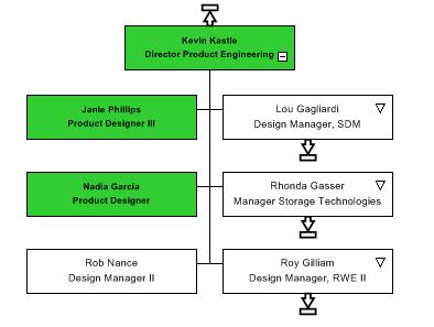
292 292 ORGCHART 10 VISIT US ORGCHARTPRO.COM


293 CHANGE BOX TO ASSISTANT STYLE USING MARKERS The easiest way to put the assistant into an assistant style is to use the markers located in the data tab. Below is screenshots on how to set up the markers for the assistants. Go to the Data tab and click on Markers and select manage rules. Select New Rule and type in what you would like to title the rule. 293 ORGCHART 10 VISIT US ORGCHARTPRO.COM

294 Select Add criteria For the criteria you will want to put yes in the find what, drop down the option for find where and select the assistant column and the comparison can be contains or you can drop down the option and select one that best fits your criteria. Click ok and ok again. Now you rule is all set up. At this point you just need to attach a marker for the assistant. Select attach Marker Check update data field value if Marker is applied. Choose the assistant option. Type in yes for data field value. Check off Update Box s arrange style and choose the assistant. Click ok. 294 ORGCHART 10 VISIT US ORGCHARTPRO.COM


295 Click Apply Active Markers Now 295 ORGCHART 10 VISIT US ORGCHARTPRO.COM
296 This will put the assistants into the assistant style. 296 ORGCHART 10 VISIT US ORGCHARTPRO.COM
297 HOW TO PUBLISH A CHART TO PDF To Publish your chart go to the file tab, publish. Choose the Interactive PDF and click next. Choose the scope of your publishing. The Current Chart is everyone within the Organization, the Active Sheet is the page that you are on and the Division and Below is the page that you are on and anyone that directly or indirectly reporting up to that person. Click next. 297 ORGCHART 10 VISIT US ORGCHARTPRO.COM
298 Please make sure the Publish individual Details Is UNCHECKED. Click next. You can include any of the below options while publishing. Click next. 298 ORGCHART 10 VISIT US ORGCHARTPRO.COM
299 Choose the High Resolution for the resolution and the Dynamic Resizable If you do NOT have any dotted line reporting relationships in the software. Static Bitmap If you DO have dotted line reporting relationships in the software. Click next. 299 ORGCHART 10 VISIT US ORGCHARTPRO.COM
300 Browse out to save the chart on your desktop or SharePoint. Click Next. Click next, Click next and Finish 300 ORGCHART 10 VISIT US ORGCHARTPRO.COM
301 HOW TO PUBLISH A SECTION OF THE CHART TO PDF To Publish your chart go to the file tab, publish. Choose the Interactive PDF and click next. Choose the scope of your publishing. The Current Chart is everyone within the Organization, the Active Sheet is the page that you are on and the Division and Below is the page that you are on and anyone that directly or indirectly reporting up to that person. Click next. Please make sure the Publish individual Details Is UNCHECKED. Click next. 301 ORGCHART 10 VISIT US ORGCHARTPRO.COM
302 You can include any of the below options while publishing. Click next. 302 ORGCHART 10 VISIT US ORGCHARTPRO.COM
303 Choose the High Resolution for the resolution and the Dynamic Resizable If you do NOT have any dotted line reporting relationships in the software. Static Bitmap If you DO have dotted line reporting relationships in the software. Click next. Browse out to save the chart on your desktop or SharePoint. Click Next. Click next, Click next and Finish The Top of the Chart: 303 ORGCHART 10 VISIT US ORGCHARTPRO.COM


304 The section of the OrgChart that I want to publish and only see that section: What you see when published out with the Division and Below Option: The VP of Marketing is now the top of the chart with the direct reports below and any one that indirectly reports up to VP of Marketing. 304 ORGCHART 10 VISIT US ORGCHARTPRO.COM
305 PUBLISHING AN ORG CHART TO POWERPOINT To publish out to PowerPoint, go to file menu and publish. Choose the PowerPoint option, click next Choose your scope that you want to publish out. The Current chart is everyone in the Organization. The active sheet is just the page that you are on. Choose if you would like to add any of the below options. 305 ORGCHART 10 VISIT US ORGCHARTPRO.COM


306 Choose the Metafile and Maximize chart area, click next Once the publishing is finished the PowerPoint will be centered on the slide for you. 306 ORGCHART 10 VISIT US ORGCHARTPRO.COM
307 ADDING 9 BOXES IN YOUR ORG CHART WITH SMART FIELDS To add 9-boxes into the OrgChart Software, you will first need to create your OrgChart from the data source. After you have the OrgChart created you can then create a rule to display the graphic in the box. To create a rule, you will go to the data tab, click on markers and select manage rule Click on New Rule 307 ORGCHART 10 VISIT US ORGCHARTPRO.COM
308 Select Add Criteria and choose the criteria for the 9 box and click ok, ok again. Once the rule is set up you will need to go to your data tab and select the Chart Data Set Click on New and name the new field that shows up. 308 ORGCHART 10 VISIT US ORGCHARTPRO.COM
309 You will change the type field from text to smart Field From there you will need have the display as a image smart field and select the add new The indicator Item will pop up and let you select the rule you created and browse out for the data graphic. The graphic is located in the library that is installed with the software. It will come up when you click browse. 309 ORGCHART 10 VISIT US ORGCHARTPRO.COM
310 Once the graphic is linked to the smart field you can click ok and ok again To create different 9 box graphics to display in the boxes you will need to go through this process multiple times. You will want to create individual rules for each of the 9 box graphics you want to display. Here is a sample of what your indicator items should look like: 310 ORGCHART 10 VISIT US ORGCHARTPRO.COM
311 You will want to uncheck the visible option and then click ok Once you are all set with you 9 box graphics you can go to your data tab and select the conditional formatting You will select add new format 311 ORGCHART 10 VISIT US ORGCHARTPRO.COM
312 You will select the rule that you want to use within the conditional format. You will need to reposition the cell positioning to make room for the 9 boxes. For the column in boxes you will want to switch it to 2 then move the name, title or any other information you have displayed currently in the chart to be moved over to the right hand side using your within the cell positioning 312 ORGCHART 10 VISIT US ORGCHARTPRO.COM
313 You will want to merge the 9 box with the cell below and click ok You will want to check off the enable the conditional formatting and/or apply the default format if box does not meet any rule. 313 ORGCHART 10 VISIT US ORGCHARTPRO.COM
314 After Applying the conditional formatting your chart will look like the below: 314 ORGCHART 10 VISIT US ORGCHARTPRO.COM


315 STEP 1. INTRODUCTORY SCREEN MS SQL IMPORT PROCEDURE FOR ORGCHART PROFESSIONAL You have to follow several simple steps, as described below, in order to import data from MS SQL server to OrgChart Professional. IMPORTANT! Please, remember to consult your DBS administrator staff or other person responsible to administer DBS server before trying to import data from MS SQL Server. STEP 1. INTRODUCTORY SCREEN (Self-explanatory step, which can be always skipped) STEP 2. CHOOSING DATA SOURCE TYPE. At this step you have to choose Microsoft SQL Server option. 315 ORGCHART 10 VISIT US ORGCHARTPRO.COM

316 STEP 3. SQL SERVER CONNECTION PARAMETERS. STEP 3. SQL SERVER CONNECTION PARAMETERS. This is the trickiest part. You have to know exact SQL Server connection parameters and access credentials. Your DBS administrator should provide you with all information necessary. DBS SERVER NAME: Exact short or fully qualified name of DBS server. It could be presented in the following forms (names are imaginary and should be replaced by correct data when used): SQL_SERVER Sql_server.domain.local Sql_server.domain.local\dbs_named_ instance INITIAL CATALOG: Most of DBS is capable of hosting several databases. You should indicate which database you wish to connect to. For instance: DBS server with name SQL_SERVER hosts 3 databases accounting, marketing_data, security_logs. You should enter accounting ( without prentices ) in Initial catalog field, if you wish to import data from accounting database. LOG ON SETTINGS: This allows you to enter specific credentials to gain access to database or use your current logon. Use your current logon option can be used if desired DBS and database are configured to accept Windows integrated security credentials. Most commonly, this option is used in Windows Domain network environment or when connecting to locally hosted DBS, which persists directly on user s computer. Specify custom username and password can be used if specific credentials are required to gain access to 316 ORGCHART 10 VISIT US ORGCHARTPRO.COM


317 STEP 4. SELECTION OF SOURCE TABLE the desired DBS and database. Username and password are provided by DBS administrator staff. STEP 4. SELECTION OF SOURCE TABLE At this step you can select desired table which will be used as data source. Procedure for this step is absolutely identical to any other strictly structural data import options, like MS Excel, MS Access, etc. STEP 5. HIERARCHY BUILDER At this step you can validate if hierarchical relation of imported data has been successfully predicted, or specify hierarchical relation rules manually. 317 ORGCHART 10 VISIT US ORGCHARTPRO.COM


318 STEP 6. DATAFIELDS CUSTOMIZATION STEP 6. DATAFIELDS CUSTOMIZATION At this step you may customize which fields should be imported, validate or manually indicate data types and set initial visibility of fields in boxes STEP 7. DIVISION CREATION POLICY At this step you may set how imported data should be split into divisions. You may choose where imported data should be inserted using Import data to options. 318 ORGCHART 10 VISIT US ORGCHARTPRO.COM

319 STEP 7. DIVISION CREATION POLICY STEP 8. READY TO GO Data gets validated and inserted into chosen destination after you press Next at this step. STEP 9. FINAL SCREEN Procedure results are displayed at the end of import. Any import errors are listed here, if there were any during the procedure. 319 ORGCHART 10 VISIT US ORGCHARTPRO.COM


320 STEP 7. DIVISION CREATION POLICY CREATING A PREFERRED BOX STYLE To add a box layout to a preferred style to use on new charts. You will first want to create a box layout by right clicking on a box, go to properties format the box the way you would like and apply to the entire chart. Once you have the box formatted click on a box and go to the design tab, click on style and select add to preferred style From there you can rename the style of box and it will be stored as a template for you to select for a new chart. 320 ORGCHART 10 VISIT US ORGCHARTPRO.COM

321 STEP 7. DIVISION CREATION POLICY Once you import a new chart and would like to apply the box style to the chart you can import the data, go to the design tab and click on the preferred styles and select the box style, apply to the entire chart and click apply format Before: After: 321 ORGCHART 10 VISIT US ORGCHARTPRO.COM

322 STEP 7. DIVISION CREATION POLICY CREATE A BACKGROUND TEMPLATE FOR YOUR ORG CHART To create a background template in the OrgChart software go to your view tab, master page. From there you can use your components tab to put legends, logos or color the background. Go to your view tab and master page Underneath Chart design within the components tab you can browse out for logos or put legends into the master page: You can also put a field name to display things like department, headcount, any field that you have brought in from your data source or that is pre-defined in the software. 322 ORGCHART 10 VISIT US ORGCHARTPRO.COM


323 STEP 7. DIVISION CREATION POLICY If you wanted to color in the background you can Right-click anywhere in the white, go to background and the fill style. 323 ORGCHART 10 VISIT US ORGCHARTPRO.COM


324 STEP 7. DIVISION CREATION POLICY After you are done setting up the master page, you can go back to the view tab and click on normal At the point you can save your template to access for new charts by going to file, save as project template. 324 ORGCHART 10 VISIT US ORGCHARTPRO.COM


325 STEP 7. DIVISION CREATION POLICY Now you can go into the design tab and browse out where the templates are saved and apply it to the charts. 325 ORGCHART 10 VISIT US ORGCHARTPRO.COM
. Assuming it does not already exist, you can add a new field to your org chart.")
 you will want to uncheck the visible option so it does not add the field into the chart yet and then click ok It will ask")
326 STEP 7. DIVISION CREATION POLICY ADDING A LABEL/FIELD TO THE BOXES IN THE CHART Do you want to add a new field to your org chart database? Fields can only be displayed on an org chart box if they are already present in the database (Chart Data Set). Assuming it does not already exist, you can add a new field to your org chart. To add a label to a box within the OrgChart you will want to start with adding a field to the Chart Data Set. The Chart Data Set is located in the Data tab. Click on new (You can name the field if you would like or keep it unnamed) you will want to uncheck the visible option so it does not add the field into the chart yet and then click ok It will ask you if you want to put the field out to the chart. You will want to say No 326 ORGCHART 10 VISIT US ORGCHARTPRO.COM


327 STEP 7. DIVISION CREATION POLICY Once the field is added you can the Right-click on the box that you would like to add the field to and go to properties. If you scroll all the way down on the left hand side you will see your unnamed field at the bottom. You can then drag the unnamed field to the main area and add it where you would like. Once in place you can add a bottom line to separate out the field as well as format the field however you would like with different fonts or bolding of the letters 327 ORGCHART 10 VISIT US ORGCHARTPRO.COM

328 STEP 7. DIVISION CREATION POLICY To fill out the information you can go into the Edit Data tab within the properties find the unnamed tab at the bottom and type in the information Then apply to the box or scope for the chart and click ok. Before: After: 328 ORGCHART 10 VISIT US ORGCHARTPRO.COM
329 STEP 7. DIVISION CREATION POLICY 329 ORGCHART 10 VISIT US ORGCHARTPRO.COM

330 STEP 7. DIVISION CREATION POLICY HOW TO CHANGE BOX SHAPE FOR THE ENTIRE CHART To change the box shape within the OrgChart Software you will want to Right-click on any box, go to Properties Once you are in the Properties, you will go to the Shape Style tab at the top, select the shape you want to apply to the chart and select Apply To: Entire Chart 330 ORGCHART 10 VISIT US ORGCHARTPRO.COM

331 STEP 7. DIVISION CREATION POLICY 331 ORGCHART 10 VISIT US ORGCHARTPRO.COM
 TWO FIELDS IN THE ORGCHART There may be times when you have two fields that you want to put together.")

332 STEP 7. DIVISION CREATION POLICY HOW TO CONCATENATE (JOIN) TWO FIELDS IN THE ORGCHART There may be times when you have two fields that you want to put together. A possible example would be separate fields for first name and last name. If you would like them joined to show a single field with both first and last name this can be done using the Concatenate function in the Chart Data Set. To concatenate fields go to the data tab and select the chart data set. Within the chart data set up will select New and type in the name of the field you would like to title it. 332 ORGCHART 10 VISIT US ORGCHARTPRO.COM


333 STEP 7. DIVISION CREATION POLICY From here you will select the type field drop down and switch it to the concatenate option and choose the fields you wish to concatenate and click ok You can select the visible field if you want to put the new field out to the existing boxes in the OrgChart. If you do not want to display the new field uncheck the viable and click ok Your new field should look the below: 333 ORGCHART 10 VISIT US ORGCHARTPRO.COM


334 STEP 7. DIVISION CREATION POLICY HOW TO MAINTAIN PAGINATION FORMATTING When you imported your data, you likely specified pagination, or how the chart was to be broken down into levels and Divisions. After import, if you made manual changes to these Divisions either by dismissing them or adding new ones you most likely do not want your manual changes being wiped out. The program s resync function will certainly recalculate your page breakdown unless you turn it off. Before resyncing you will want to make sure that you have the box formatting set within the box properties. Right-click on a box, go to properties, select the set this layout as a default for the new boxes Apply to the entire chart Click ok Then before you resync the data you will want to go through the resync properties first. This is to set your formatting and divisions within the software. The first screen will allow you to browse out to a new spreadsheet for resyncing. Best practice is to keep the spreadsheet named the same and saved over the existing spreadsheet so the link is never broken. If you happen to rename or move the spreadsheet you can come into the resync properties and browse out to link it back up. Click Next 334 ORGCHART 10 VISIT US ORGCHARTPRO.COM


335 STEP 7. DIVISION CREATION POLICY The software will load up the spreadsheet to make sure there is a live and working link between the software and the spreadsheet. Click Next You will want to verify how you created your hierarchy and click Next 335 ORGCHART 10 VISIT US ORGCHARTPRO.COM


336 STEP 7. DIVISION CREATION POLICY Any updated fields that can be checked, should be checked. Click Next The last page you will want to select the do not create and Apply active Markers after the synchronization process The do not create will hold you formatting. If you dismissed divisions, put additional fields into the boxes, changed the layout of the boxes, any type of formatting. The do not create will hold it. The apply active Markers will redistribute the color codes you may have in the software. Click Finish 336 ORGCHART 10 VISIT US ORGCHARTPRO.COM

337 STEP 7. DIVISION CREATION POLICY After you complete the resync properties you can then go resync the data. 337 ORGCHART 10 VISIT US ORGCHARTPRO.COM


338 STEP 7. DIVISION CREATION POLICY RESIZE BOXES USING FORMAT PAINTER The OrgChart software defaults to automatic box sizing. If you want to override automatic formatting and make boxes a particular size you can do this. Keep in mind that while boxes on a page may be the same size, box sizes from page to page may vary, based on the chart layout and the number of boxes being squeezed onto the page. Whether you use manual or automatic sizing this will be the case. If you want to perform manual sizing this article may help. To get all the boxes one size select a box that is the size you want for all boxes. Go to the home tab, click on the format painter Go into options and click on the manual check box for the size. Uncheck every other check box, and apply it to the entire chart on the right hand size and click ok. 338 ORGCHART 10 VISIT US ORGCHARTPRO.COM
339 STEP 7. DIVISION CREATION POLICY This will automatically adjust the box sizes for you throughout the OrgChart. 339 ORGCHART 10 VISIT US ORGCHARTPRO.COM

 Browse out to where the photos")
340 STEP 7. DIVISION CREATION POLICY PHOTOS IN ORGCHART There are two ways to upload photos into the OrgChart software. 1 ST OPTION FOR ADDING PHOTOS The first option is to have the photos set as hyperlinks within the data source. To create a hyperlink you will need to go to the photo cell of the employee you want to upload the photo to and Right-click on the cell, go to Edit Hyperlink (You can also have the photos housed in the same folder as the excel or data source and have the names listed in the photo fields instead of a hyperlink) Browse out to where the photos are located and click on it so it is hyperlinked in the data source and click ok 340 ORGCHART 10 VISIT US ORGCHARTPRO.COM


341 STEP 7. DIVISION CREATION POLICY Once all the photos are hyperlinked in the spreadsheet, you can upload your information into the OrgChart software. Once you have your information uploaded into the software you can Right-click on any box, go to properties. 341 ORGCHART 10 VISIT US ORGCHARTPRO.COM

342 STEP 7. DIVISION CREATION POLICY Within the Properties you are able to add information into the box including the photos. In the lower right hand corner is two photo layouts available for you to choose from. Once you choose the layout you want. Click Set this layout as a default for the new Boxes and then Apply to the Entire Chart 342 ORGCHART 10 VISIT US ORGCHARTPRO.COM
343 STEP 7. DIVISION CREATION POLICY 2 ND OPTION FOR ADDING PHOTOS The second option to upload your photos into the OrgChart is to do it manually. To upload your photos manually first you will need upload your data or manually create your chart. After you have the chart created you can Right-click on the box that you want to upload a photo to and go to properties. 343 ORGCHART 10 VISIT US ORGCHARTPRO.COM


344 STEP 7. DIVISION CREATION POLICY Go into the Edit Data tab and find the photo field. Click on the ( ) to bring up your browse. You can then browse to where your photos are located and link up the photo to the box. Click ok 344 ORGCHART 10 VISIT US ORGCHARTPRO.COM


345 STEP 7. DIVISION CREATION POLICY After you have the image linked to the box, you will want to go to the define layout tab and select the photo field on the lower right-hand side. You will want to click Apply to Selection 345 ORGCHART 10 VISIT US ORGCHARTPRO.COM
346 STEP 7. DIVISION CREATION POLICY You will want to repeat the manual process for the other boxes within the OrgChart until all the photos are linked to the box. 346 ORGCHART 10 VISIT US ORGCHARTPRO.COM

347 STEP 7. DIVISION CREATION POLICY RESIZING PHOTOS IN THE ORGCHART You can resize your photos that are in the OrgChart by double clicking on a photo and choosing a desired size. Change to size you like. From there you will want to go to your home tab select the format painter. Make sure all of your options are selected and apply to the entire chart. 347 ORGCHART 10 VISIT US ORGCHARTPRO.COM


348 STEP 7. DIVISION CREATION POLICY It will resize the photos all at once: 348 ORGCHART 10 VISIT US ORGCHARTPRO.COM
349 STEP 7. DIVISION CREATION POLICY SHORTCUTS IN ORGCHART BOX OPERATIONS Right mouse click With box selected this brings up the local menu. Alt-A Add a position. If a box is selected a new box appears as a subordinate. Ctrl-A Select all boxes Shift-Delete Cut Ctrl-C Copy Delete Delete a box Alt-Enter Shows properties for a selected box. Local menu shown when right clicking on a box or group of boxes. Ctrl-R Toggles between Move mode and Resize mode o Resize mode: 349 ORGCHART 10 VISIT US ORGCHARTPRO.COM

350 STEP 7. DIVISION CREATION POLICY o Move mode: Mouse hover over box Brings up the properties icon CHART SHEET NAVIGATION Shift-Left Mouse Button With mouse on chart page, this allows you to drag / pan the page in any direction. Right-click on chart page for local menu. Alt-G Show grid Ctrl-Shift-R Show Rulers Paste - Ctrl-V 350 ORGCHART 10 VISIT US ORGCHARTPRO.COM
Excel Select a template category in the Office.com Templates section. 5. Click the Download button.
 Microsoft QUICK Excel 2010 Source Getting Started The Excel Window u v w z Creating a New Blank Workbook 2. Select New in the left pane. 3. Select the Blank workbook template in the Available Templates
Getting Started with. PowerPoint 2010
 Getting Started with 13 PowerPoint 2010 You can use PowerPoint to create presentations for almost any occasion, such as a business meeting, government forum, school project or lecture, church function,
OrgPublisher 10.1 End User Help
 OrgPublisher 10.1 End User Help Table of Contents OrgPublisher 10.1 End User Help Table of Contents Making the Chart Work for You... 5 Working with a PluginX chart... 6 How to Tell if You're Working with
Introduction to Microsoft Word 2008
 1. Launch Microsoft Word icon in Applications > Microsoft Office 2008 (or on the Dock). 2. When the Project Gallery opens, view some of the available Word templates by clicking to expand the Groups, and
Word 2013 Quick Start Guide
 Getting Started File Tab: Click to access actions like Print, Save As, and Word Options. Ribbon: Logically organize actions onto Tabs, Groups, and Buttons to facilitate finding commands. Active Document
Using SymPrint to Make Overlays, Templates & More...
 Welcome to SymPrint SymPrint is an easy-to-use tool for creating communication overlays, worksheets, classroom activities and more using a modern toolbar and common-sense interface modeled after the programs
Excel 2013 for Beginners
 Excel 2013 for Beginners Class Objective: This class will familiarize you with the basics of using Microsoft Excel. Class Outline: Introduction to Microsoft Excel 2013... 1 Microsoft Excel...2-3 Getting
Microsoft Excel 2007
 Learning computers is Show ezy Microsoft Excel 2007 301 Excel screen, toolbars, views, sheets, and uses for Excel 2005-8 Steve Slisar 2005-8 COPYRIGHT: The copyright for this publication is owned by Steve
MICROSOFT OFFICE. Courseware: Exam: Sample Only EXCEL 2016 CORE. Certification Guide
 MICROSOFT OFFICE Courseware: 3263 2 Exam: 77 727 EXCEL 2016 CORE Certification Guide Microsoft Office Specialist 2016 Series Microsoft Excel 2016 Core Certification Guide Lesson 1: Introducing Excel Lesson
Sample Chapters. To learn more about this book, visit the detail page at: go.microsoft.com/fwlink/?linkid=192147
 Sample Chapters Copyright 2010 by Online Training Solutions, Inc. All rights reserved. To learn more about this book, visit the detail page at: go.microsoft.com/fwlink/?linkid=192147 Chapter at a Glance
Introducing Gupta Report Builder
 Business Reporting Chapter 1 Introducing Gupta Report Builder You can use Report Builder to design reports. This chapter describes: Our approach to building reports. Some of the reports you can build.
Productivity Tools Objectives
 Word 2003 Understand Microsoft Office Word 2003 Launch Microsoft Office Word 2003 Open Documents Understand The Working Screen Experiment With The Working Screen Navigate Documents Close Documents And
Table of Contents. Word. Using the mouse wheel 39 Moving the insertion point using the keyboard 40 Resume reading 41
 Table of Contents iii Table of Contents Word Starting Word What is word processing? 2 Starting Word 2 Exploring the Start screen 4 Creating a blank document 4 Exploring the Word document window 5 Exploring
Anleitungen für Word 2016 als Word-Dokument zum Ausdrucken und fürs Intranet
 Anleitungen für Word 2016 als Word-Dokument zum Ausdrucken und fürs Intranet 19 Text and Tabs Tabs (tab stops) help you to write a list, for example, for an order or invoice. Larger spaces should not be
Lehigh University Library & Technology Services
 Lehigh University Library & Technology Services Start Word Open a file called day2 Microsoft WORD 2003 Day 2 Click the Open button on the Standard Toolbar Go to the A: drive and highlight day2 and click
Quick Access Toolbar. You click on it to see these options: New, Open, Save, Save As, Print, Prepare, Send, Publish and Close.
 Opening Microsoft Word 2007 in the practical room UNIT-III 1 KNREDDY 1. Nyelvi beállítások az Office 2007-hez (Language settings for Office 2007 (not 2003)) English. 2. Double click on the Word 2007 icon
With ClaroIdeas you can quickly and easily create idea maps using a combination of words, symbols and pictures.
 Welcome to ClaroIdeas ClaroIdeas is a fresh tool to support the creation and editing of concept maps or idea maps using visual and audio components. It has been specifically developed to support people
Productivity Tools Objectives 1
 Productivity Tools Objectives 1 Word 2003 Understand Microsoft Office Word 2003 Launch Microsoft Office Word 2003 Open Documents Understand The Working Screen Experiment With The Working Screen Navigate
Excel 2013 Intermediate
 Excel 2013 Intermediate Quick Access Toolbar... 1 Customizing Excel... 2 Keyboard Shortcuts... 2 Navigating the Spreadsheet... 2 Status Bar... 3 Worksheets... 3 Group Column/Row Adjusments... 4 Hiding
Contents. Launching Word
 Using Microsoft Office 2007 Introduction to Word Handout INFORMATION TECHNOLOGY SERVICES California State University, Los Angeles Version 1.0 Winter 2009 Contents Launching Word 2007... 3 Working with
PowerPoint 2016 Basics for Mac
 1 PowerPoint 2016 Basics for Mac PowerPoint 2016 Basics for Mac Training Objective To learn the tools and features to get started using PowerPoint more efficiently and effectively. What you can expect
Microsoft Windows SharePoint Services
 Microsoft Windows SharePoint Services SITE ADMIN USER TRAINING 1 Introduction What is Microsoft Windows SharePoint Services? Windows SharePoint Services (referred to generically as SharePoint) is a tool
To learn more about the Milestones window choose: Help Help Topics Select the Index tab and type in the feature. For Example toolbox.
 To learn more about the Milestones window choose: Help Help Topics Select the Index tab and type in the feature. For Example toolbox. 1 of 12 CHOOSE THE DATES TAB TO: 1. Set the schedule s Date Range.
Intro to Excel. To start a new workbook, click on the Blank workbook icon in the middle of the screen.
 Excel is a spreadsheet application that allows for the storing, organizing and manipulation of data that is entered into it. Excel has variety of built in tools that allow users to perform both simple
Using Microsoft Office 2003 Intermediate Word Handout INFORMATION TECHNOLOGY SERVICES California State University, Los Angeles Version 1.
 Using Microsoft Office 2003 Intermediate Word Handout INFORMATION TECHNOLOGY SERVICES California State University, Los Angeles Version 1.2 Summer 2010 Table of Contents Intermediate Microsoft Word 2003...
POWERPOINT BASICS: MICROSOFT OFFICE 2010
 POWERPOINT BASICS: MICROSOFT OFFICE 2010 GETTING STARTED PAGE 02 Prerequisites What You Will Learn USING MICROSOFT POWERPOINT PAGE 03 Microsoft PowerPoint Components SIMPLE TASKS IN MICROSOFT POWERPOINT
Excel 2010 Level 1: The Excel Environment
 Excel 2010 Level 1: The Excel Environment Table of Contents The Excel 2010 Environment... 1 The Excel Window... 1 File Tab... 1 The Quick Access Toolbar... 4 Access the Customize the Quick Access Toolbar
Press the Plus + key to zoom in. Press the Minus - key to zoom out. Scroll the mouse wheel away from you to zoom in; towards you to zoom out.
 Navigate Around the Map Interactive maps provide many choices for displaying information, searching for more details, and moving around the map. Most navigation uses the mouse, but at times you may also
Lesson 5: Review and Deliver Presentations Microsoft PowerPoint 2016 IN THIS CHAPTER, YOU WILL LEARN HOW TO
 Lesson 5: Review and Deliver Presentations Microsoft PowerPoint 2016 IN THIS CHAPTER, YOU WILL LEARN HOW TO Set up presentations for delivery. Preview and print presentations. Prepare speaker notes and
PowerPoint 2016 Building a Presentation
 PowerPoint 2016 Building a Presentation What is PowerPoint? PowerPoint is presentation software that helps users quickly and efficiently create dynamic, professional-looking presentations through the use
PowerPoint Spring 2002
 PowerPoint 2000 Spring 2002 Table of Contents I. INTRODUCTION... 1 II. GETTING STARTED... 1 A. Opening PowerPoint... 1 B. The Mouse Pointer... 1 C. Working with Text... 2 1. Windows Control Buttons...
Computer Applications Information Processing 1
 Computer Applications Information Processing 1 Lesson 8: Organize and Arrange Content Microsoft Word 2016 IN THIS CHAPTER, YOU WILL LEARN HOW TO Reorganize document outlines. Arrange objects on the page.
Microsoft Excel Important Notice
 Microsoft Excel 2013 Important Notice All candidates who follow an ICDL/ECDL course must have an official ICDL/ECDL Registration Number (which is proof of your Profile Number with ICDL/ECDL and will track
Contents. Introduction 15. How to use this course 18. Session One: Basic Skills 21. Session Two: Doing Useful Work with Excel 65
 Contents Introduction 15 Downloading the sample files... 15 Problem resolution... 15 The Excel version and locale that were used to write this book... 15 Typographical Conventions Used in This Book...
Microsoft PowerPoint Tutorial
 Microsoft PowerPoint Tutorial Contents Starting MS PowerPoint... 1 The MS PowerPoint Window... 2 Title Bar...2 Office Button...3 Saving Your Work... 3 For the first time... 3 While you work... 3 Backing
Double-click on the PowerPoint icon on the desktop. Another way to access the program is to click on the Start button>programs>powerpoint.
 MS PowerPoint 2013 I. About PowerPoint A. What is it? Microsoft PowerPoint is a powerful tool to create professional looking presentations and slide shows. PowerPoint allows you to construct presentations
Microsoft Excel 2010 Basic
 Microsoft Excel 2010 Basic Introduction to MS Excel 2010 Microsoft Excel 2010 is a spreadsheet software in the new Microsoft 2010 Office Suite. Excel allows you to store, manipulate and analyze data in
Microsoft Word 2007 on Windows
 1 Microsoft Word 2007 on Windows Word is a very popular text formatting and editing program. It is the standard for writing papers and other documents. This tutorial and quick start guide will help you
San Pedro Junior College. WORD PROCESSING (Microsoft Word 2016) Week 4-7
 Week 4-7") WORD PROCESSING (Microsoft Word 2016) Week 4-7 Creating a New Document In Word, there are several ways to create new document, open existing documents, and save documents: Click the File menu tab and then
WORD PROCESSING (Microsoft Word 2016) Week 4-7 Creating a New Document In Word, there are several ways to create new document, open existing documents, and save documents: Click the File menu tab and then
Introduction to Microsoft Office 2016: Word
 Introduction to Microsoft Office 2016: Word Last Updated: September 2018 Cost: $2.00 Microsoft Word is a word processing software. You can use it to type letters, reports, and other documents. This class
Quick Start Guide - Contents. Opening Word Locating Big Lottery Fund Templates The Word 2013 Screen... 3
 Quick Start Guide - Contents Opening Word... 1 Locating Big Lottery Fund Templates... 2 The Word 2013 Screen... 3 Things You Might Be Looking For... 4 What s New On The Ribbon... 5 The Quick Access Toolbar...
On the Web sun.com/aboutsun/comm_invest STAROFFICE 8 DRAW
 STAROFFICE 8 DRAW Graphics They say a picture is worth a thousand words. Pictures are often used along with our words for good reason. They help communicate our thoughts. They give extra information that
Numbers Basics Website:
 Website: http://etc.usf.edu/te/ Numbers is Apple's new spreadsheet application. It is installed as part of the iwork suite, which also includes the word processing program Pages and the presentation program
PowerPoint Launching PowerPointX
 PowerPoint 2004 Launching PowerPointX 1. Start PowerPoint by clicking on the PowerPoint icon in the dock or finding it in the hard drive in the Applications folder under Microsoft Office 2004. PowerPoint
To create a notebook on desktop version 1. Open One Note 2. File > New. o FILE. Options
 OneNote Training When you open OneNote for the first time there will be notebooks already started and you can see them on the left hand side. There is an introduction section that you can go through, if
PowerPoint Instructions
 PowerPoint Instructions Exercise 1: Type and Format Text and Fix a List 1. Open the PowerPoint Practice file. To add a company name to slide 1, click the slide 1 thumbnail if it's not selected. On the
Chapter 4 Printing and Viewing a Presentation Using Proofing Tools I. Spell Check II. The Thesaurus... 23
 PowerPoint Level 1 Table of Contents Chapter 1 Getting Started... 7 Interacting with PowerPoint... 7 Slides... 7 I. Adding Slides... 8 II. Deleting Slides... 8 III. Cutting, Copying and Pasting Slides...
WEEK NO. 12 MICROSOFT EXCEL 2007
 WEEK NO. 12 MICROSOFT EXCEL 2007 LESSONS OVERVIEW: GOODBYE CALCULATORS, HELLO SPREADSHEET! 1. The Excel Environment 2. Starting A Workbook 3. Modifying Columns, Rows, & Cells 4. Working with Worksheets
Designing a Presentation
 4 Designing a Presentation LESSON SKILL MATRIX Skill Exam Objective Objective Number Formatting Presentations with Themes and Layouts Change the slide master theme or background. 1.3.1 Changing Slide Backgrounds
Introduction. Watch the video below to learn more about getting started with PowerPoint. Getting to know PowerPoint
 PowerPoint 2016 Getting Started With PowerPoint Introduction PowerPoint is a presentation program that allows you to create dynamic slide presentations. These presentations can include animation, narration,
Open. Select the database and click. Print. Set printing options using the dropdown menus, then click the
 The Original Quick Reference Guides Microsoft Access 2010 Access is a tool for creating and managing databases collections of related records structured in an easily accessible format such as a table,
Getting Started with. PowerPoint 2010
 Getting Started with 13 PowerPoint 2010 You can use PowerPoint to create presentations for almost any occasion, such as a business meeting, government forum, school project or lecture, church function,
Microsoft PowerPoint 2016 Basics Unit 9 Final Review - Student Notes Directions: Fill in the blanks.
 Directions: Fill in the blanks. 1. PowerPoint Window Layout 2. File Tab When clicked, opens - automatically opens the Info option by default Holds the following options: - Info - New - Open - Save - Save
Inserting Information into PowerPoint
 LESSON 6 6.1 Inserting Information into PowerPoint After completing this lesson, you will be able to: Change the layout of a slide. Insert a clip art image. Scale an image. Insert and format a table. Insert
CHAPTER 1 COPYRIGHTED MATERIAL. Finding Your Way in the Inventor Interface
 CHAPTER 1 Finding Your Way in the Inventor Interface COPYRIGHTED MATERIAL Understanding Inventor s interface behavior Opening existing files Creating new files Modifying the look and feel of Inventor Managing
Changing Worksheet Views
 PROCEDURES LESSON 1: TOURING EXCEL Starting Excel 1 Click the Start button 2 Click All Programs 3 Click the Microsoft Office folder icon 4 Click Microsoft Excel 2010 Naming and Saving (Ctrl+S) a Workbook
FLIR Tools+ and Report Studio
 Creating and Processing Word Templates http://www.infraredtraining.com 09-20-2017 2017, Infrared Training Center. 1 FLIR Report Studio Overview Report Studio is a Microsoft Word Reporting module that is
SPARK. User Manual Ver ITLAQ Technologies
 SPARK Forms Builder for Office 365 User Manual Ver. 3.5.50.102 0 ITLAQ Technologies www.itlaq.com Table of Contents 1 The Form Designer Workspace... 3 1.1 Form Toolbox... 3 1.1.1 Hiding/ Unhiding/ Minimizing
Interface. 2. Interface Adobe InDesign CS2 H O T
 2. Interface Adobe InDesign CS2 H O T 2 Interface The Welcome Screen Interface Overview The Toolbox Toolbox Fly-Out Menus InDesign Palettes Collapsing and Grouping Palettes Moving and Resizing Docked or
Word Tips & Tricks. Status Bar. Add item to Status Bar To add an itme to the status bar, click on the item and a checkmark will display.
 Status Bar The status bar is located on the bottom of the Microsoft Word window. The status bar displays information about the document such as the current page number, the word count in the document,
Creating Interactive PDF Forms
 Creating Interactive PDF Forms Using Adobe Acrobat X Pro for the Mac University Information Technology Services Training, Outreach, Learning Technologies and Video Production Copyright 2012 KSU Department
User Guide. Web Intelligence Rich Client. Business Objects 4.1
 User Guide Web Intelligence Rich Client Business Objects 4.1 2 P a g e Web Intelligence 4.1 User Guide Web Intelligence 4.1 User Guide Contents Getting Started in Web Intelligence 4.1... 5 Log into EDDIE...
This guide will show you how to create a basic multi-media PowerPoint presentation containing text, graphics, charts, and audio/video elements.
 This guide will show you how to create a basic multi-media PowerPoint presentation containing text, graphics, charts, and audio/video elements. Before starting the steps outlined in this guide, it is recommended
Paragraph Formatting 4
 Paragraph Formatting 4 LESSON SKILL MATRIX Skill Exam Objective Objective Number Formatting Paragraphs Set indentation. 2.2.7 Setting Line Spacing in Text and Between Paragraphs Set line spacing. Modify
OpenForms360 Validation User Guide Notable Solutions Inc.
 OpenForms360 Validation User Guide 2011 Notable Solutions Inc. 1 T A B L E O F C O N T EN T S Introduction...5 What is OpenForms360 Validation?... 5 Using OpenForms360 Validation... 5 Features at a glance...
Creating and Modifying Charts
 Creating and Modifying Charts Introduction When you re ready to share data with others, a worksheet might not be the most effective way to present the information. A page full of numbers, even if formatted
Table of Contents. Contents
 Spring 2009 R.A. Table of Contents Contents Opening PowerPoint... 2 PowerPoint 2007 Interface... 2 PowerPoint Features... 2 Creating, Opening and Saving Presentations... 3 Creating a Presentation... 3
New York City College of Technology. Microsoft Word Contact Information:
 New York City College of Technology Microsoft Word 2016 Contact Information: 718-254-8565 ITEC@citytech.cuny.edu Opening Word 2016 Begin by clicking on the bottom left corner icon on the desktop. From
Interface. 2. Interface Photoshop CS/ImageReady CS for the Web H O T
 2. Interface Photoshop CS/ImageReady CS for the Web H O T 2. Interface The Welcome Screen Interface Overview Using the Toolbox Using Palettes Using the Options Bar Creating a Tool Preset Resetting Tools
Ms excel. The Microsoft Office Button. The Quick Access Toolbar
 Ms excel MS Excel is electronic spreadsheet software. In This software we can do any type of Calculation & inserting any table, data and making chart and graphs etc. the File of excel is called workbook.
Microsoft PowerPoint 2007 Tutorial
 Microsoft PowerPoint 2007 Tutorial Prepared By:- Mohammad Murtaza Khan I. T. Expert Sindh Judicial Academy Contents Getting Started... 5 Presentations... 5 Microsoft Office Button... 5 Ribbon... 6 Quick
Status Bar: Right click on the Status Bar to add or remove features.
 Excel 2013 Quick Start Guide The Excel Window File Tab: Click to access actions like Print, Save As, etc. Also to set Excel options. Ribbon: Logically organizes actions onto Tabs, Groups, and Buttons to
ORGANIZING YOUR ARTWORK WITH LAYERS
 9 ORGANIZING YOUR ARTWORK WITH LAYERS Lesson overview In this lesson, you ll learn how to do the following: Work with the Layers panel. Create, rearrange, and lock layers and sublayers. Move objects between
Microsoft Excel 2010 Tutorial
 1 Microsoft Excel 2010 Tutorial Excel is a spreadsheet program in the Microsoft Office system. You can use Excel to create and format workbooks (a collection of spreadsheets) in order to analyze data and
MS Word 2010 An Introduction
 MS Word 2010 An Introduction Table of Contents The MS Word 2010 Environment... 1 The Word Window Frame... 1 The File Tab... 1 The Quick Access Toolbar... 4 To Customize the Quick Access Toolbar:... 4
Creating a PowerPoint Presentation
 powerpoint 1 Creating a PowerPoint Presentation Getting Started 1. Open PowerPoint from the "Start" "Programs" Microsoft Office directory. 2. When starting PowerPoint, it usually starts with a new blank
B.Sc. VI SEM (CS+BIO)
") Unit I Creating presentation using Slide master and Template in various Themes & Variants. If you want your presentation to contain more than one theme (layouts that contain backgrounds, colors, fonts,
Unit I Creating presentation using Slide master and Template in various Themes & Variants. If you want your presentation to contain more than one theme (layouts that contain backgrounds, colors, fonts,
Week 5 Creating a Calendar. About Tables. Making a Calendar From a Table Template. Week 5 Word 2010
 Week 5 Creating a Calendar About Tables Tables are a good way to organize information. They can consist of only a few cells, or many cells that cover several pages. You can arrange boxes or cells vertically
Creating Reports in Access 2007 Table of Contents GUIDE TO DESIGNING REPORTS... 3 DECIDE HOW TO LAY OUT YOUR REPORT... 3 MAKE A SKETCH OF YOUR
 Creating Reports in Access 2007 Table of Contents GUIDE TO DESIGNING REPORTS... 3 DECIDE HOW TO LAY OUT YOUR REPORT... 3 MAKE A SKETCH OF YOUR REPORT... 3 DECIDE WHICH DATA TO PUT IN EACH REPORT SECTION...
For more tips on using this workbook, press F1 and click More information about this template.
 Excel: Menu to ribbon reference To view Office 2003 menu and toolbar commands and their Office 2010 equivalents, click a worksheet tab at the bottom of the window. If you don't see the tab you want, right-click
What can Word 2013 do?
 Mary Ann Wallner What can Word 2013 do? Provide the right tool for: Every aspect of document creation Desktop publishing Web publishing 2 Windows 7: Click Start Choose Microsoft Office > Microsoft Word
Microsoft Word 2011 Tutorial
 Microsoft Word 2011 Tutorial GETTING STARTED Microsoft Word is one of the most popular word processing programs supported by both Mac and PC platforms. Microsoft Word can be used to create documents, brochures,
Microsoft Excel 2010 Part 2: Intermediate Excel
 CALIFORNIA STATE UNIVERSITY, LOS ANGELES INFORMATION TECHNOLOGY SERVICES Microsoft Excel 2010 Part 2: Intermediate Excel Spring 2014, Version 1.0 Table of Contents Introduction...3 Working with Rows and
Microsoft How to Series
 Microsoft How to Series Getting Started with EXCEL 2007 A B C D E F Tabs Introduction to the Excel 2007 Interface The Excel 2007 Interface is comprised of several elements, with four main parts: Office
Chapter 2 Using Slide Masters, Styles, and Templates
 Impress Guide Chapter 2 Using Slide Masters, Styles, and Templates OpenOffice.org Copyright This document is Copyright 2007 by its contributors as listed in the section titled Authors. You can distribute
Introduction to PowerPoint
 L E S S O N 1 Introduction to PowerPoint Lesson objectives Suggested teaching time To become familiar with PowerPoint's presentation capabilities, you will: 40-50 minutes a b c Start the program, open
Microsoft Word Part I Reference Manual
 Microsoft Word 2002 Part I Reference Manual Instructor: Angela Sanderson Computer Training Coordinator Updated by: Angela Sanderson January 11, 2003 Prepared by: Vi Johnson November 20, 2002 THE WORD SCREEN
Spreadsheets Microsoft Office Button Ribbon
 Getting started with Excel 2007 you will notice that there are many similar features to previous versions. You will also notice that there are many new features that you ll be able to utilize. There are
Contents. Introduction 13. Putting The Smart Method to Work 16. Session One: Basic Skills 23
 Contents Introduction 13 Feedback... 13 Downloading the sample files... 13 Problem resolution... 13 Typographical Conventions Used In This Book... 14 Putting The Smart Method to Work 16 Excel version and
COPYRIGHTED MATERIAL. Using Adobe Bridge. Lesson 1
 Lesson Using Adobe Bridge What you ll learn in this lesson: Navigating Adobe Bridge Using folders in Bridge Making a Favorite Creating metadata Using automated tools Adobe Bridge is the command center
Skills Exam Objective Objective Number
 Overview 1 LESSON SKILL MATRIX Skills Exam Objective Objective Number Starting Excel Create a workbook. 1.1.1 Working in the Excel Window Customize the Quick Access Toolbar. 1.4.3 Changing Workbook and
A Step-by-step guide to creating a Professional PowerPoint Presentation
 Quick introduction to Microsoft PowerPoint A Step-by-step guide to creating a Professional PowerPoint Presentation Created by Cruse Control creative services Tel +44 (0) 1923 842 295 training@crusecontrol.com
BusinessObjects Frequently Asked Questions
 BusinessObjects Frequently Asked Questions Contents Is there a quick way of printing together several reports from the same document?... 2 Is there a way of controlling the text wrap of a cell?... 2 How
Table of Contents. 1. Creating a Microsoft Excel Workbook...1 EVALUATION COPY
 Table of Contents Table of Contents 1. Creating a Microsoft Excel Workbook...1 Starting Microsoft Excel...1 Creating a Workbook...2 Saving a Workbook...3 The Status Bar...5 Adding and Deleting Worksheets...6
Policy Commander Console Guide - Published February, 2012
 Policy Commander Console Guide - Published February, 2012 This publication could include technical inaccuracies or typographical errors. Changes are periodically made to the information herein; these changes
Budget Exercise for Intermediate Excel
 Budget Exercise for Intermediate Excel Follow the directions below to create a 12 month budget exercise. Read through each individual direction before performing it, like you are following recipe instructions.
DOING MORE WITH WORD: MICROSOFT OFFICE 2007
 DOING MORE WITH WORD: MICROSOFT OFFICE 2007 GETTING STARTED PAGE 02 Prerequisites What You Will Learn USING MICROSOFT WORD PAGE 03 Viewing Toolbars Adding and Removing Buttons MORE TASKS IN MICROSOFT WORD
PowerPoint X. 1. The Project Gallery window with the PowerPoint presentation icon already selected. 2. Click on OK.
 PowerPoint X Launching PowerPointX 1. Start PowerPointX by clicking on the PowerPoint icon in the dock or finding it in the hard drive in the Applications folder under Microsoft PowerPoint. PowerPoint
Microsoft Word 2010 Tutorial
 1 Microsoft Word 2010 Tutorial Microsoft Word 2010 is a word-processing program, designed to help you create professional-quality documents. With the finest documentformatting tools, Word helps you organize
Sending image(s) to report Click Send Snapshot on any screen in Dolphin3D and choose the Send to Report option
 to report Click Send Snapshot on any screen in Dolphin3D and choose the Send to Report option") Dolphin 3D Reports Sending image(s) to report Click Send Snapshot on any screen in Dolphin3D and choose the Send to Report option Creating a report step by step 1. Generate the desired images in Dolphin3D
Dolphin 3D Reports Sending image(s) to report Click Send Snapshot on any screen in Dolphin3D and choose the Send to Report option Creating a report step by step 1. Generate the desired images in Dolphin3D