ITEM: Digilock ATS - Recess Mount, No Pull Handle, Brushed Nickel, Black for 3/4" Door BRAND: Digilock $138.3
|
|
|
- Oswin Roberts
- 5 years ago
- Views:
Transcription
: $138.")

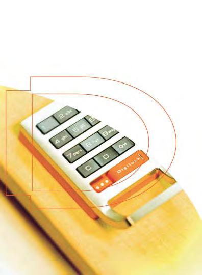
1 Specifications PRODUCT #: DLATS619013X ITEM: Digilock ATS - Recess Mount, No Pull Handle, Brushed Nickel, Black for 3/4" Door BRAND: Digilock SOURCE FOR PURCHASE: SpaEquip, Inc. 211 Wappo Ave., Calistoga, CA p: f: LIST PRICE (USD): $138.3 FEATURES: Digilock ATS - Recess Mount, No Pull Handle for 3/4" Door Comes in brushed nickel finish w/black Color Ring and/or Insert. SPECIFICATIONS: Dimensions: Electrical: Suggested Outlet: Plumbing: Notes: Warranty: Certifications: Country of Origin: Installed By: 2.8" H, 2.14" W 4 x AA batteries N/A None None 2 Year Limited Warranty None United States Client's Contractor

2 To initialize new locks: (Step 1) To initialize new locks: (Step 3) NOTE: New locks will operate only with c K until initialized. Step one will initialize one lock and register the manager bypass keys to one lock. Step three will paste the information that was copied to the programming key in step two to all locks at your facility. (This step is only required if you have more than one lock). Quick Operating & Programming Digilock Shared Usage Locks Standard & High Security ** If you have more than one lock you will complete steps one and two on one lock and step three on the remaining locks in your facility. 1) Touch the programming key (red) to the key slot for one full second. The LED will turn on. 2) Touch each manager bypass key (black) to the key slot, one at a time. A single blink of the led and a single beep after touching each manager bypass key is an indicator that the manager bypass key to be registered has been properly touched to the lock. 3) Touch the programming key (red) to the key slot for one full second. A double tone signifies successful initialization of your lock. 1) Go to any lock that requires programming. 2) Touch the programming key (red) to the key slot. A double tone signifies that the lock was successfully initialized and the manager bypass keys were successfully registered to the lock. 3) Repeat this procedure to all locks in your facility. It is recommended to test the registration of the manager bypass keys to the lock(s). To do this operate the lock(s) with the manager bypass key(s) by following the operating instructions To Operate with Manager Bypass Key. Digilock Accessory Guide To initialize new locks: (Step 2) To Add Additional Manager Bypass Keys : Programming Key (Solid Red) Registers Manager Override Keys to locks. Provides external power in case of battery failure. Each lock accepts only (1) programming key. Manager Bypass Key (Solid Black) Provides management access to locks. Provides external power in case of battery failure. Each lock accepts up to (25) manager bypass keys. ADA User Key (Solid Blue) ADA compliant user key. Allows user to lock and unlock any available lock. Step two will copy the registration of the manager bypass keys to the programming key. This step is to initialize or program more than one lock. 1) Go to the lock you initialized in step 1. 2) Press: c K 6 6 K 3) Touch the programming key (red) to the key slot for one full second. A double tone signifies that the registered manager bypass keys were successfully copied to the programming key. This step will add additional manager bypass keys to one lock and does not erase any previously registered manager bypass keys. 1) Go to one lock. 2) Press: c K 5 5 K The LED will flash. 3) Touch the programming key (red) to the key slot for one full second. The LED is solid. 4) Touch each manager bypass key (black) to the key slot, one at a time. A single blink of the led and a single beep after touching each manager bypass key is an indicator that the manager bypass key to be registered has been properly touched to the lock. 5) Touch the programming key (red) to the key slot for one full second. A double tone signifies successful Addition of manager keys. If you need to add these manager keys to additional locks: 1) Follow instructions To initialize new locks: (step 2). 2) Follow instructions To initialize new locks: (step 3).
3 To operate with a user code: To lock: 1) Find an available lock. 2) press: c ` ` ` ` K (any four-digit code) To unlock: 1) At same lock. 2) press: c ` ` ` ` K (same code used to lock) To operate with an ADA user key: To lock: 1) Find an available lock. 2) touch the ADA user key (blue) to key slot. To unlock: 1) At same lock. 2) Touch the ADA user key (blue) to key slot. For a lost programming key: For lost or stolen keys: Contact your Digilock Product Representative to order a replacement programming key. For a lost manager bypass key(s): 1) collect all remaining manager keys or order additional keys from your Digilock Product Representative. 2) At one lock press c K 5 5 K The LED will flash. 3) Touch the programming key (red) to the key slot for one full second. The LED is solid. 4) Touch the programming key (red) to the key slot for one full second. The LED will turn off and all registered manager keys will be erased on the one lock. 5) Follow instructions To add additional manager bypass keys. If you have more than one lock, continue with steps 6 and 7. 6) Follow instructions To initialize new locks: (step 2). 7) Follow instructions To initialize new locks: (step 3). Additional Product Features If you have the high security platform, this product line is capable of audit trail with use of a software programming kit. For additional information regarding this feature contact your Digilock product representative. To operate with the manager bypass keys: To lock or unlock: 1) touch a registered manager bypass key (black) to key slot. To operate with the programming key: To lock or unlock: 1) Press: c K 2) Insert programming key (red) to key slot. Troubleshooting 1) No Audible feedback when c button is pressed: A) the batteries have failed- replace batteries located in the rear unit. B) poor connection on door- remove lock from door and reinstall. C) The lock is in sleep state. Try again after one minute. 2) Lock does not unlock: A) listen for additional audible feedback for an indicator as to what is going on. B) Try operating with manager bypass key or programming key C) Contact your Digilock Product Representative or Digilock customer support. 3) Lock emits 2 sets of three beeps during operation: A) low battery indicator- replace batteries located in the rear unit. 4) lock emits 10 rapid beeps during operation: A) binding indicator- the lock is binding with the strike plate. Press firmly on the door while operating. If binding is a frequent occurrence, the strike plate and/or door hinges need to be aligned with the lock. For Additional Product and/or Product Information: Visit: support@digilock.com Contact: Digilock or your Digilock Product Representative 5341 Old Redwood Highway, Suite 200, Petaluma, CA Phone: (800) (707) Fax: (800) (707)
4 To Enable Automatic Unlock: Automatic Unlock 1 is an optional feature that will only be activated when it is programmed. It can be disabled at any time with the registered manager bypass key. Press the C Key Press the key symbol Touch a registered Manager Bypass Key to the key slot until you hear an audible feedback The LED will emit a solid red light Press the 1 through 8 for the number of hours Press the key symbol A double tone signifies successful programming For example, if 3 is pressed Digilock will automatically unlock after 3 hours of being locked. 1 Warning: Automatic Unlock is an optional feature that functions only if it is activated. Digilock is shipped with this feature disabled. Activation of this feature is not recommended as it may pose liability issues depending on your facilities operation.
5 To Disable Automatic Unlock: Automatic Unlock 1 is an optional feature that will only be activated when it is programmed. It can be disabled at any time with the registered manager bypass key. Press the C Key Press the key symbol Touch a registered Manager Bypass Key to the key slot until you hear an audible feedback The LED will emit a solid red light Press 9 to disable the Automatic Unlock Feature Press the key symbol A double tone signifies successful programming 1 Warning: Automatic Unlock is an optional feature that functions only if it is activated. Digilock is shipped with this feature disabled. Activation of this feature is not recommended as it may pose liability issues depending on your facilities operation.
6 To Enable the Flashing LED: Press the C Key Press the key symbol Touch a registered Manager Bypass Key to the key slot until you hear audible feedback The LED will emit a solid red light Press 9 to enable the Flashing LED feature Press the key symbol A double tone signifies successful programming
7 To Disable the Flashing LED: Press the C Key Press the key symbol Touch a registered Manager Bypass Key to the key slot until you hear audible feedback The LED will emit a solid red light Press 0 to disable the Flashing LED feature Press the key symbol A double tone signifies successful programming
8 Troubleshooting Guide Changing the Batteries 1) the batteries are located in the rear unit of the lock. To change the batteries, remove the rear unit cover plate: Problem: The lock operates with = ` and does not recognize any codes/keys. A) The lock has not been initialized. Refer to the operating/programming guide to initialize the lock. No Audible feedback when = button is pressed: A) The lock is in sleep state. Wait one minute and try again. B) The batteries have failed- use manager bypass key to unlock the lock and replace batteries located in the rear unit. C) Poor connection on door- remove lock from door and reinstall. Problem: Lock does not unlock: A) Listen for additional audible feedback for an indicator as to what is going on. B) Try operating with manager bypass key or programming key C) Contact your Digilock Product Representative or Digilock customer support. One beep and one red flash occurs when inserting manager bypass key, user key and/or programming key. A) the key is not recognized by the lock. Try another key or refer to lock programming instructions to register the key to the lock. Standard Security Rear 3 screws 3) replace the rear unit cover plate and test the digilock. High Security Rear 4 screws 2) remove existing batteries and replace with new batteries. Depending on lock model. Standard Security Rear 2 9 volt High Security Rear Long Body - 4 AA Short Body - 4 AAA Note: to achieve optimal battery life use premium alkaline batteries. Lock Indicators Lock emits 2 sets of three beeps during operation: A) low battery indicator i) replace batteries located in the rear unit. ii) If batteries fail in the locked position, the manager bypass key and programming key will supply bypass power to the lock. Use the manager bypass key or programming key to unlock the lock and replace batteries immediately. Lock emits 10 rapid beeps during operation: A) binding indicator i) If the lock is locked, the lock is binding with the strike plate or the items in the locker. Press firmly on the door while operating. If binding is a frequent occurrence, the strike plate and/or door hinges need to be aligned with the lock. ii) If the lock is unlocked, the screws/locking nuts may be overtightened. Loosen the screws/locking nuts and try to operate. If binding indicator is still heard, remove lock from door. Assemble lock in hands and test operation. If the lock works, reinstall on door. If the lock still gives the binding indicator, contact Digilock Customer Support. For Additional Product and/or Product Information: Visit: support@digilock.com Contact: Digilock or your Digilock Product Representative 5341 Old Redwood Highway, Suite 200 Petaluma, CA Phone: (800) (707) Fax: (800) (707) Copyright 2008 Digilock, #59-TS001-01
9 Management System Installation & Administration Guide
10 Contents Contacting Technical Support...1 Digilock Key Management System...2 The Installation and Administration Guide...2 Finding Additional Help...2 Digilock Audit Trail Kit Includes...3 Installing the Digilock Software...4 Digilock Software Overview...4 System Requirements...5 Installing the Software...6 Installing the Programming Box...7 Uninstalling the Software...9 Managing the Digilock Software...10 Digilock Software Administrator Overview...10 Launching the Digilock Software...11 Initializing the Software Programming Key...12 Login Safeguards...13 System Administration Menu Overview...13 Granting Digilock Software User Rights...14 Adding, Editing & Deleting Program Users...15 i
11 Contacting Technical Support: For Technical Support or Warranty Service, contact: Security People, Inc. Makers of Digilock Attn.: Warranty Department 3675 Enochs St. Santa Clara, CA Phone: (800) Phone: (707) Web: For Additional Products and Product Accessories, contact: Security People, Inc. Makers of Digilock 5341 Old Redwood Hwy Suite # 200 Petaluma, CA Phone: (800) Phone: (707) sales@digilock.com Web: 1
12 The Digilock Management System: The Installation and Administration Guide This guide is designed for the owner and/or the person responsible for installing and administrating the Digilock Management Software. For information on the operation and use of the Digilock Management Software see the Digilock Management System s User Guide. Finding Additional Help For information on using the Digilock Software see the Digilock Management System User Guide. For problems using the software see the Troubleshooting section of the Digilock Management Software User Guide. Additional help is also available by accessing the Help menu (or by pressing F1) in the Digilock Software. 2
13 Digilock Audit Trail Kit Includes: Digilock Management Software: A CD ROM containing the Digilock Management Software for maintaining and programming authorized management bypass keys to the lock groups. Programming Box: Provides a communication link between the Digilock H Series Locks and the Software Programming Key. Software Programming Key: Programs the H Series Locks and receives audit trail information from the H Series Locks. User Guide: Information for using the Digilock Management System. Installation and Administration Guide: Installing the Digilock Management Software and issuing Software User Rights. 3
14 Installing the Digilock Software: Digilock Software Overview Please read this entire chapter before installing the Digilock Software. This chapter demonstrates: System Requirements Installing the Digilock Software Installing the Programming Box Uninstalling the Digilock Software 4
15 System Requirements: Successful operation of the Digilock Software requires: Windows 95 or higher A 486 DX processor or higher 15 Megabytes of hard drive or more 8 Megabytes of RAM or more A CD-ROM drive 1 free USB You will need additional hard drive space to maintain the Management Software. 5
16 Installing the Software: WARNING: DO NOT INSTALL THE PROGRAMMING BOX BEFORE INSTALLING THE SOFTWARE. To install the software: 1. Close any applications that are currently running. 2. Insert the Digilock Management Software CD into the CD-ROM. The CD should automatically load. If the CD does not automatically load, double click the SETUP.EXE file on the CD-ROM. 4. Click OK to install the software. 5. At the Welcome Screen, follow The Digilock Setup Wizard and click Finish to complete the setup. NOTE: Once the software is installed, the Programming Box must be installed before launching the software. 6


17 Installing the Programming Box: Before installing the Programming Box, be sure you have installed the software. To install the programming box: 1. Close out of any open applications. 2. Insert the Programming Box USB connector to an available USB Port on your computer. 3. The Welcome to the Found New Hardware Window will appear. Select No, Not at this Time and click Next. 7


18 4. At the next prompt, select Install the Software Automatically (recommended) and click next. 5. Click Finish to close the wizard 8
19 Uninstalling the Software: To remove the Digilock Management Software: 1. From your Windows desktop, select Start-Settings- Control Panel. 2. Double-click on Add/Remove Programs. 3. From the Add/Remove Programs tab, select KMH from the program list. 4. Select Change/Remove to uninstall the Digilock Software. 5. Select Yes to completely remove KMH and all of its components. 9
20 Managing the Digilock Management Software: The System Administrator controls who has access to the software and what level of access others have when entering the Digilock Management Software. This chapter demonstrates: Launching the Digilock Software Initializing the Software Programming Key System Administration Menu Overview Granting Digilock Software User Rights Adding, editing and deleting Digilock Software Users. 10

.")
21 Launching the Digilock Management Software: The first time you login to the Digilock Management Software you will use a default User Identification (ID) and Password You will be required to change the defaults immediately. This new User ID and Password becomes the System Administrator. Please be sure to write down your new User ID and Password To launch the Digilock Management Software: 1. Double click the KMH icon on your Windows desktop. This displays the Login Window: The first time you login to the Digilock Management Software, use these defaults: (You will be prompted to change these defaults immediately). Default User ID: sa Default Password: sesame 2. Change the default fields with your information and click OK. 3. Be sure to write down your new User ID and Password. 11

 into the Programming Box until you are notified that the key has been")

22 Initializing the Software Programming Key: After changing the default User ID and Password, you will be prompted to Make the First Programming Key. Click OK to continue. Software Programming Key When the Insert Key prompt is displayed, insert the Software Programming Key (red) into the Programming Box until you are notified that the key has been registered as an authorized Programming Key. Click OK to continue. The software program will launch. Note: Once the programming key is registered, you must always use the software to maintain your locks. 12

23 Login Safeguards: The Digilock Management Software displays the following message when the User ID or Password is incorrect: Click OK to continue. The Digilock Management Software Displays this when the password is incorrect for the second time. After three consecutive incorrect log ins, the Digilock Management Software shuts down for five minutes while the following message is displayed: After this timed message clears, you can login to the Digilock Management Software again. 13
24 System Administration Menu: From the System Administration menu, you can add, edit or delete Digilock Management Software Users, or change your password. Defining User Access: Each User entered into this system will have a User ID, Password and a pre-defined user level of access. These access levels are designed as follows. -User - has access to all the Digilock Management Software features. -Administrator - has access to all Digilock Management Software features and in addition, can add, edit and delete Digilock Management Systems Users. Granting Digilock Management Software User Rights: NOTE: In order to maintain security, it is important that you give consideration to how others will access and use this software. The first User you will add into the Digilock Management Software is yourself as the System Administrator. After adding a new System Administrator, all additional Software User s will have User rights. If you wish to give a User additional rights, you must edit their user information file. (See page 17 to edit a user information file). 14


25 Adding a User Information File: 1. From the menu bar, select: System Administration-Users. 2. Click Add to display the User Information Window: -User is the default Access Level for new Users. To make this user an Administrator, you must first create the new user and then edit their file. 3. Enter the ID for this User. 5. Enter the User s First Name. 5. Enter the User s Last Name. 6. Enter and Confirm a Password for this User. 7. When you are done, click OK. 15

26 Deleting a User Information File: 1. From the menu bar, select: System Administration- Users. 2. Select the User file. 3. Click Delete. 4. This displays the Delete Confirm prompt. Click Yes to delete this User. 16
27 To Edit a User: 1. From the menu bar, select: System Administration-Users. 2. Click here to select a User ID from the drop-down list 3. Click Edit to modify the selected User Information file. NOTE: The User ID field cannot be edited. In the User Information Window you can edit: User's First Name. User's Last Name. User's Access Level User's Password When you are done, click OK. NOTE: If you have modified the Password and Confirm Password fields, this box displays, click OK to continue. 17

28 Management System User Guide
29 Contents Contacting Technical Support...1 Getting Started...2 Main Lock Tabs...3 Finding Additional Help...4 Digilock H Series Lock Overview...5 Launching the Software Program...6 Login Safeguards...7 Changing Your Password...8 Using the Programming Key...9 Initializing the Programming Key Steps to Setup Your Digilock System...11 Step 1 -Adding Keyholders...12 Step 2 -Adding Manager Bypass Keys...14 Step 3 -Assigning Manager Bypass Keys...15 Step 4 -Adding a New Lock Group...16 Step 5 -Programming a Keyholder to a Lock Group...21 Additional Features...25 Keyholders Tab...26 Editing Keyholders...27 Deleting Keyholders...28 Keys Tab...29 Identifying Manager Bypass Keys...31 Processing Lost Manager Bypass Keys...32 Returning Manager Bypass Keys to Stock...33 Printing Signature Cards for Manager Keys...12 i
30 Lock Groups Tab...35 Editing Lock Group Information...36 Removing Lock Groups...37 Retrieving an Audit Trail...38 System Data Tab...41 Update the Programming of the Locks...42 Printing a List of Locks to be Programmed...45 Backing Up /Restoring the Database...47 Backing up the Database...48 Restoring the Database...50 Updating the Time...52 Processing Reports...53 Key Report by Keyholder...54 Key Report by Location...55 Location Report by Key...56 Location Report by Keyholder...57 Last Audit Report...58 Lost and Trash Keys Report...59 Overdue Key Report...60 Lock Operating Guide...61 Digilock HTS/HTV/HTH...62 Digilock HPS/HPV/HPH...63 To Change the User Code with the Manager Bypass Key...64 To Change the User Code with the Existing User Code...65 ii
31 Troubleshooting Guide...66 Problem Descriptions and Solutions...67 Index...71 iii
32 Contacting Technical Support For Technical Support or Warranty Service, contact: Security People, Inc. Makers of Digilock Attn.: Warranty Department 3675 Enochs St. Santa Clara, CA Phone: (800) Phone: (707) Website: For Additional Products and Product Accessories, contact: Security People, Inc. Makers of Digilock 5341 Old Redwood Hwy Suite # 200 Petaluma, CA Phone: (800) Phone: (707) sales@digilock.com Website: 1
33 2 Getting Started
34 Getting Started Follow each chapter in this manual to view and operate the Digilock Management Software features, including: Main Lock Tabs The Keyholders Tab maintains a list of all persons to be issued Manager Bypass Keys. The Keys Tab maintains a list of Manager Bypass Keys issued to Keyholders The Locks Tab maintains a list of the H Series Lock Groups. The System Data Tab manages the assignment of Lock Functions and Manager Bypass Keys to the H Series Locks. 3
35 Finding Additional Help Additional information regarding software installation instructions and software user access rights can be found in the Digilock Installation and Administration Guide. A full help menu is available in the software at anytime by accessing the Help menu (or by pressing F1) in the Digilock Software. 4


36 Digilock H Series Lock Overview: Digilock H Series Locks are parts of Digilock s High Security product line providing a 1/2 deadlocking mechanism with audit trail. Digilock H Series Lock Programming Box The Programming Box provides a communication link between the Digilock Software and a Programming or Manager Bypass Key. Manager Keys are used to provide access to the locks. Red Programming Key Black Manager Bypass Key Programming Keys are used to program the H Series locks and to receive audit trail information from the locks. 5


37 Launching the Digilock Software Program Note: User ID s and Password information is reviewed in the Digilock Installation and Administration Guide. To launch the Digilock Management Software: 1. Double-click the KMH icon on your Windows desktop. 2. Enter your User ID 3. Enter your password 4. When you are done, click OK NOTE: The User ID and Password fields are case sensitive. 6


38 Login Safeguards The Digilock Management Software displays the following message when the User ID or Password is incorrect: Click OK to continue. The Digilock Management Software Displays this when the password is incorrect for the second time. After three consecutive incorrect logins, the Digilock Management Software shuts down for five minutes while the following message is displayed: After this timed message clears, you can login to the Digilock Management Software again. 7


39 Changing your Password NOTE: If you forget or lose your password, contact your system administrator, or see the Digilock Installation and Administration Guide. Only the User currently logged into the Digilock Software can access the Password Change Option on the System Administration menu. To change your password: 1. From the Digilock menu bar, select System Administration - Password Change. 2. Enter and Confirm the new Password you will use when logging into the system (up to 25 characters). 3. When you are done click OK. 8
40 Using the Programming Key One Programming Key is issued with each Digilock Key Management System. It is important to maintain the security of this key at all times. The Programming Key transfers information to and from each Digilock H Series Lock. The Programming Key is used to: Initialize each H Series Lock Program Management access information into the H Series Lock(s) Retrieve audit information from the H Series Lock(s) 9

41 Initializing the Programming Key Before a Programming Key can be used, it needs to be initialized by the Digilock Software. The first Programming Key should have been initialized during the software installation. If you need to register an additional Programming Key, or were not able to register your key during the installation process, follow these steps: 1. From the Digilock menu bar, select: Utilities-Make Programming Key. 2. When this prompt is displayed, insert the Programming Key (red) into the Programming Box. 3. When the Programming Key is registered, this message is displayed. To clear it, click OK. 10
42 5 Steps to Set-Up Your Digilock System 11
43 Adding Keyholders -Step 1 Navigate to the KEYHOLDERS TAB: 1. On the Keyholders Tab, click the Add New button to display a new user information window. 12
. 6. Click OK to enter the keyholder into the Keyholder Database. 7.")
44 2. Enter the Last and First Name of the Keyholder up to 30 characters. (Required field entry). 3. Enter the keyholders position (optional field). 4. Enter their department (optional field) 5. Enter a primary phone number, up to 15 characters (optional field). 6. Click OK to enter the keyholder into the Keyholder Database. 7. A new line is shown for this keyholder and is displayed in the keyholder database. Repeat steps 1-7 to add additional keyholders (maximum of 25 allowed). 13

45 Adding Manager Bypass Keys -Step 2 Navigate to the KEYS TAB: 1. Go to the Keys Tab and click the Add New button. 2. When this prompt is displayed, insert the Manager Bypass Key(s) (black) into the Programming Box one at a time 3. As each key is inserted, a new line is added into the Keys database. Click Finish when you are through. 14

46 Assigning Keyholders to Manager Bypass Keys -Step 3 New Manager Bypass Keys are assigned as stock in the Keys Database as they are added. 1. On the Key ID line you are assigning, select the keyholder field to display a drop down button of available keyholders. 2. Click on the drop down button to display a list of available Keyholders. 3. Click a Keyholders name to assign the Key to the Keyholder. 15

47 Adding a New H Series Lock Group -Step 4 Navigate to the LOCKS GROUP TAB Lock Groups allow management of assigned manager bypass keys to a set or system of locks. You are not limited to the number of lock groups that you create. For example: You may choose to have two lock groups, one that manages the women's lockers and one that manages the men's lockers. NOTE: If you have both shared and assigned use locks, you will need to create one lock group for each type of lock. To add a new H Series Lock Group into the Locks Database: 1. Click the Add New Button to display the lock information window. 2. Enter a Group # 3. Enter a Group Name 16
48 4. Enter a Lock Description (optional). 5. Enter a Lock Location (optional). 6. Click on the arrow and select your Lock Type For HPS/HPV/HPH locks continue to page 18 For HTS/HTV/HTH locks continue to page 19 -To identify your lock type: -HPS/HPV/HPH locks are assigned to an individual user and are unlocked with an assigned fourdigit code. The locking mechanism is a latch. -HTS/HTV/HPH locks are shared by multiple users and can be locked with any four-digit code when they are unlocked. The locking mechanism is a bolt. 17
49 Adding a New HPS/HPV/HPH Lock Group -Step 4A The following selections will need to be made for HPS/HPV/ HPH locks: Make sure LOCK TYPE is: HPS/HPV/HPH Choose an open time. (The default is 6 seconds). Click OK to add the H Series Lock into the Locks database. Lock Information: HPS/HPV/HPH 18

50 Adding a New HTS/HTV/HTH Lock Group -Step 4B The following selections will need to be made for HTS/HTV/ HTH locks: Make sure LOCK TYPE is: HTS/HTV/HTH Lock Information: HTS/HTV/HTH 19
51 If you would like the lock to auto unlock after a set number of hours, select the number of hours under the drop down menu -auto unlock (hours). If you would like the lock to automatically unlock at a set time check the corresponding box and enter the correct unlock time. Note: If you want the lock to unlock at a set period of time, you must set the unlock time for the weekdays, for Saturday and for Sunday individually. FLASH LED WHEN LOCKED: Keep this checked if you want the LED to flash when the lock is locked. (Default setting). Click OK to add the H Series Lock into the Locks database. 20

52 Programming a Keyholder to a Lock Group -Step 5 Navigate to the SYSTEM DATA TAB On this page you will see the lock groups going across the page and the keyholders going down. You must assign a check mark in the grid space to assign a key holder access to a lock group. To do this: double-click in the correct grid space for both the Keyholder and the Lock Group. (Double-click again to clear the grid space). 1. When you are ready to register your locks with the manager bypass key information, click on the Transfer to Programming Key Button on the bottom left of the system data tab. 21
53 2. If more than one lock group requires programming, choose the lock group you wish to program and click OK to continue and click OK to continue 22
54 4. When this prompt is displayed, insert the Programming Key (red) into the Programming Box. 5. When this message appears, your programming key contains the manager key registration information. Click OK to clear this message. 6. Insert the Programming Key in the key slot of each lock that belongs to the lock group in the previous step. A double tone from each lock indicates successful manager key registration. Test the lock(s) to make sure that the Manager Bypass Key(s) were successfully registered to the lock(s). Follow the Operating Instructions To Operate with a Manager Bypass Key. 23
 all of the lock groups.")
55 13. The grid space turns White when the Digilock H Series Lock is confirmed. 14. Repeat this process to register the manager bypass key(s) all of the lock groups
56 Keyholders Tab 25

57 Editing Keyholder Information After a keyholder is entered into the database, you can edit or review the Keyholder Information. To do this: 1. On the Keyholder Tab, double click in any row to view or edit the Keyholder Information record for a selected keyholder. 2. Click OK when finished. 26

58 Deleting Keyholders NOTE: If the Keyholder has been assigned a Manager Bypass Key, you will be prompted to remove it before you can delete the Keyholder. Keyholders can be easily removed from the database. To do this: 1. On the Keyholder Tab, single click on the appropriate Keyholder line to highlight their user line. 2. Click Delete to remove this keyholder and click Yes to confirm. 27
59 28 Keys Tab

60 Identifying a Manager Bypass Key The Identify button can be used to match an assigned Manager Bypass Key to a Keyholder. To do this: 1. Click the Identify button on the Keys Tab. 2. When the Insert Key prompt is displayed, insert the Manager Bypass Key (black) into the Programming Box. 29

61 The User Information window identifies the Key ID. The Key ID is displayed. 3. Click Cancel to return to the Keys tab. 30

62 Processing Lost Manager Bypass Keys When a Manager Bypass Key is lost, you will need to remove it from your database to prevent someone else from gaining access to your locks. To do this: 1. Select the appropriate key line in the database. 2. Click Lost Keys. 3. Click Yes to confirm the key as Lost. Note: You will need to update the programming of your lock groups after removing a Manager Bypass Key. 31

63 Returning Manager Bypass Keys to Stock When an assigned key is no longer used, you can return it to stock. 1. Select the appropriate key line in the database. 2. Click Return Stock. 3. Click Yes to confirm this Manager Bypass Key as Stock. 32
64 Printing Signature Cards for Manager Bypass Keys When assigning Manager Bypass Keys, you may choose to print out a Signature Card. To do this: 1. Select the appropriate key line. 2. Click Signature. 33


65 The Signature Note window is displayed. 3. Type additional notes you want to include with the Signature Card. 4. Click OK to continue and display the Signature Report. 34
66 Lock Groups Tab 35

67 Editing Lock Group Information After a lock has been added into the Locks database, to edit or review Lock information: 1. Double-click in the appropriate lock row to display the Lock Information window. 2. Change the Lock Group Information 3. When you are done, click OK. Note: Editing a lock group information may require you to update the programming of your locks. 36


68 Removing Lock Groups To remove a Lock Group from the database: 1. Single click the appropriate lock row to select the lock group to be removed 2. Click the Remove button. 3. When prompted confirm that the lock group number is the group you would like to remove and click YES. 4. Click YES to continue if you are sure you want to delete the lock group. 37
 into the Programming Box. 3.")
69 Retrieving an Audit Trail After you have registered a Manager Bypass Key to an H Series lock, an audit trail is recorded every time a code or key is introduced to the lock. To retrieve audit information from a H Series Lock: 1. On the locks tab click Initialize Audit. 2. When this prompt is displayed, insert the Programming Key (red) into the Programming Box. 3. This prompt is displayed when the Programming Key is initialized for audit. Click OK to clear it. 38

 into the Programming Box. 8.")
70 4. Insert the Programming Key into the appropriate H Series Lock. The lock flashes green while retrieving the information. Remove the key when once an audible tone is heard. 5. From the Keys tab, click Download Audit. 6. Enter a lock description to identify the lock you are auditing and click OK. 7. When this prompt is displayed, insert the Programming Key (red) into the Programming Box. 8. To delete the previous Audit Report, and view the new Audit Report click OK. 9. Audit report will be displayed in a new window for viewing, printing and/or exporting. 39
71 Sample Audit Report Audit information can be viewed, exported or printed. To view or print the previously retrieved audit information: From the Digilock menu bar, select Utilities-Audit Trail-Last Audit Report. The report will be displayed in a new window. 40
72 System Data Tab 41
73 Update the Programming of your Locks The KMH software program is utilized to register the manager bypass keys to your locks. In order to transfer this registration information to your programming key, the column on the system data tab must be pink. If you have found your manager bypass key(s) is not registered to your lock(s), follow these steps to update the manager key registration information. 1. Navigate to the System Data Tab 2. Double click on the name of the lock group that you wish to update. The lock information window will appear. 3. Click the Update Button. 42
74 4. The lock information window will disappear and the column of the lock group that requires updating will turn pink. 5. Click on the transfer to programming key button on the bottom of the system data tab. 6. If more than one lock group requires programming, select the lock group you wish to program and click OK to continue. 7. When this prompt is displayed, insert the Programming Key (red) into the Programming Box. 43
75 8. When the prompt below appears, your programming key contains the manager key registration information. Click okay to clear the message. 9. Insert the Programming Key in each lock that belongs to the lock group in the previous step. A double tone from each lock indicates successful manger key registration. Test the lock(s) to make sure that the Manager Bypass Key(s) were successfully registered to the lock(s). Follow the Operating instructions To Operate with a Manager Bypass Key. 10. The grid space for the lock group you updated will turn white. If you have additional lock groups that are pink, repeat steps 5 through

76 Printing a List of Locks to be Programmed To print a list of Lock Groups that need to be programmed. 1. Click Print Program 2. Click OK. 45

77 The print window displays a list of Digilock H Series Lock Groups that need to be programmed. Click here to Print a list of Locks Groups to be Programmed. 46
78 Backing Up and Restoring 47


79 Backing up the Digilock Database File It is a good idea to back up the Digilock database file at least once a week. To do this: 1. From the Digilock menu bar, select System Administration-Database Backup. 2. Click OK 3. Click Yes again 4. Select a drive and path to save the backup file. 48

80 5. Enter a name for the backup file. 6. When you are done, click Save. 7. When the backup file is saved, click OK to clear this prompt, and log back into the Digilock Software. 8. This prompt displays when the database file is Restored. Click OK to clear it, and log back into the Digilock Software. 49


81 Restoring the Digilock Database File If you have migrated to a new computer, or your computer crashed, you can use restore your lock database if you have a back up saved. To do this: 1. From the Digilock menu bar, select System Administration-Database Restore. 2. When prompted, enter the administrator password. 3. Click Okay to Exit the Program 4. Click Yes to confirm 50

82 5. Navigate through your computer to select the drive and path of the backup you wish to restore. 6. To restore, click OK and then click OK to re-enter the software. 8. Enter the user name and password to open the restored database. 51
 into the Programming Box. 3.")
83 Updating Time on the Programming Key Any time there is a time change, it is necessary to update your locks with the new date and time. To do this: 1. From the Digilock menu bar, select: Utilities-Update Time for Programming Key 2. When this prompt is displayed, insert the Programming Key (red) into the Programming Box. 3. When the Programming Key is registered, this message is displayed. To clear it, click OK. 4. Touch the Programming Key to each lock to update them with the new date and time. 52
84 Processing Reports 53

85 Key Report by Keyholder This report displays a list of User Keys assigned to each User. To view the Key Report by Keyholder On the Reports menu, select Key Report by Keyholder: 54

86 Key Report by Location This report displays a list of User Keys assigned by Lock Location. To view the Key Report by Location: On the Reports menu, select Key Report by Location. 55

87 Location Report by Key This report displays a list of Locks assigned by Key Location. To view the Location Report by Key: On the Reports menu, select Location Report by Key. 56

88 Location Report by Keyholder This report displays a list of Lock Locations assigned by Keyholder. To view the Location Report by Keyholder. On the Reports menu, select Location Report by Keyholder. 57
89 Last Audit Report This report displays the Last Audit Report retrieved from a H Series Lock. To view the Last Audit Report: On the Reports menu, select Last Audit Report. 58

90 Lost and Trash Keys Report This report displays a list of User Keys assigned as Lost or Trash. To view the Lost and Trash Key Report: On the Reports menu, select Lost and Trash Key Report. 59

91 Overdue Key Report This report displays a list of User Keys that have passed their assigned due date. To view the Overdue Key Report: On the Reports menu, select Overdue Key Report. 60
92 Operating Instructions 61
93 Digilock HTS/HTV/HTH Operating Instructions To Lock with a User Code: -Press c -Enter any four-digit code of your choice -Press K to lock The "LED" will flash red when locked (unless this feature has been disabled) To Unlock with a User Code: -Press c -Enter the same four-digit code used to lock the lock -Press K to unlock To Lock with a Manager Bypass Key: -Touch a registered Manager Bypass Key (black) to the key slot To Unlock with a Manager Bypass Key: -Touch a registered Manager Bypass Key (black) to the key slot To Unlock with a Programming Key: -Press c -Press the K -Touch a registered Programming Key (red) to the key slot 62
94 Digilock HPS/HPV/HPH Operating Instructions To Unlock with a User Code: -Press c -Enter your four-digit registered user code -Press the K to unlock -Pull the door open while the green LED is lit -Closing the door will automatically relock the lock To register a user code, see pages 73 and 74 To Unlock Using the Manager Bypass Key: -Touch a registered Manager Bypass Key (black) to the key slot -Pull the door open while the green LED is lit -Closing the door will automatically relock the lock To Unlock with a Programming Key: -Press c -Press the K -Touch a registered Programming Key (red) to the key slot -Pull the door open while the green LED is lit -Closing the door will automatically relock the lock 63
95 To Change a User Code Using the Manager Bypass Key: (HPS/HPV/HPH only) -Press c -Press the K -Touch a registered Manager Bypass Key to the key slot until you hear audible feedback The LED will emit a solid green light -While the light is on, enter the new 4-digit User Code -Press the K The LED will emit a solid red light -Re-enter the new 4-digit user code -Press the K to end the programming mode A double tone signifies successful programming Test the lock to make sure that the new User Code was entered properly by following the operating instructions To Unlock with a User Code. 64
96 To Change a User Code Using the Existing User Code: (HPS/HPV/HPH only) -Press c -Press the K -Enter the existing 4-digit user code -Press the K The lock will be in programming mode when the "LED" emits a solid green light -Enter the new 4-digit user code -Press the K The "LED" will emit a solid red light -Re-enter the new 4-digit user code -Press the K A double tone signifies successful programming Test the lock to make sure that the new User Code was entered properly by following the operating instructions To Unlock with a User Code. 65
97 66 Troubleshooting Guide
98 Problem Descriptions and Solutions Problem Before the Digilock Software program loads, an Overdue Keys message is displayed. Solution In the Keys database, you have assigned a due date to keys that have surpassed the due date. Cannot write Zone data to the Key. Fail to update the Programming Key You pulled the Programming Key out of the Programming Box before the key was read. 1. Clear the Transfer failed, Try again prompt. 2. Select Transfer to Programming Key, and follow the prompts reenter the Programming Key into the Programming Box. 3. When the Loaded successfully prompt is displayed, clear it and then remove the Programming Key. The lock only operates with ck The manager keys have not been registered to the lock. Refer to the 5 Steps to Setup Your Digilock System, beginning on page
99 Problem There is no audible sound when touching the keypad and the lock is unlocked. Possible Reason Low Batteries Lock is not properly installed. Solution Replace the batteries, visit com for instructions on replacing the batteries. Uninstall the lock and assemble in your hands. If the lock is functioning it is not defective. Reinstall the lock on your door. If the lock continues to have problems (it may not be adjusted for your door thickness) or if the lock does not function while uninstalled contact Digilock Customer Service. There is no audible sound when touching the keypad and the lock is locked Lock is in sleep state Low Batteries Wait one full minute and try the user code again, or unlock with a valid manager bypass key Use the manager bypass key to unlock the lock and replace the batteries. 68
100 Problem The lock locks and unlocks normally, but emits an additional double-set of three red blinks and three audible beeps When entering a valid operating code/key the LED emits a double-set of three red blinks and three audible beeps and the lock does not unlock. The lock continues to go into sleep state. Possible Reason Low Batteries Low Batteries Invalid operating code Solution Replace the batteries, visit com for instructions on replacing the batteries. Replace the batteries, visit com for instructions on replacing the batteries. Use a valid manager bypass key to unlock the lock When entering a valid operating code/key the LED emits ten red blinks and ten audible beeps and the lock does not unlock The lock is binding Press firmly in on the lock while entering a valid operating code/key. If this problem persists the strike plate may need to be adjusted. 69
101 Problem The lock is locked; the manager key does not allow access There is no audible sound when touching the keypad and all of the above have been tried. Possible Reason The lock has failed to recognize valid operating code/keys Solution Reset the lock, visit for instructions on resetting the lock. 70
102 Index A Audit Trail, 38 B Box, Programming, 5 C Changing your password, 8 D Digilock H Series Overview, 5 Overview, 5 I Initializing Audit, 38 Digilock H Series Locks, 5 Programming Key, 9, 10 L Last Audit Report, 58 Location Report by Key, 56 Report by Keyholder, 57 Lock Groups Editing, 36 Initializing, 21 Removing, 37 Login safeguards, 7 Lost and Trash Keys report, 59 M Making Programming Key, 10 Manager Bypass Keys, O Overdue Key Report, 60 K Keys Processing lost, 31 Programming, 10, 14 Returning to Stock, 32 Manager Bypass, 5, 29 Keyholder Adding, 12 Assigning, 21 Deleting, 27 71
103 P Password, changing, 8 Programming Box, 5 Key, 10, 14 R Reports Audit, 38, 58 Key by Keyholder, 54 Key by Location, 55 Location by Key, 56 Location by Keyholder, 57 Lost and Trash Keys, 59 Overdue Keys, 60 S System Data, 21, T Technical Suppor, 1t Transfer to programming, 21, 42 Troubleshooting, U Update time, Programming Key, 52 72
Lock Parts. Keys. Key Insertion. Front Unit. Rear Unit. Product Guide. Standard Keypad Bolt Mechanism. Connection Options
 Axis locks with a keypad interface are operated by a 4-digit User Code or by an ADA compliant User Key. Manager Keys provide management access and external power. Programming is accomplished via a Programming
Product Guide. Key Button. Pull Handle
 Aspire locks with a keypad interface are operated by a 4-7 digit User Code or by an ADA compliant User Key. Manager Keys provide management access and external power. Programming is accomplished via a
Product Guide. Key Button. Pull Handle
 Aspire locks with a keypad interface are operated by a 4-7 digit User Code or by an ADA compliant User Key. Manager Keys provide management access and external power. Programming is accomplished via a
Setup. Programming Instructions. Product Guide
 Cue locks with a keypad interface are operated by a -digit User Code or by an ADA compliant User Key. Manager Keys provide management access and external power. Programming is accomplished via a Programming
Lock Orientation. Keys. Key Insertion. Product Guide. Horizontal with Knob on Left
 Lock Orientation Versa locks with a keypad interface are operated by a 4-7 digit User Code or by an ADA compliant User Key. Manager Keys provide management access and external power. Programming is accomplished
Lock Parts. Keys. Key Insertion. Front Unit. Rear Unit. Product Guide. User Credential User Key. Touch RFID Latch Mechanism. Connection Options
 Axis locks with a touch RFID interface are operated by an RFID credential or by an ADA compliant User Key. Manager Keys provide management access and external power. Programming is accomplished via a Programming
Lock Orientation - Views. Keys. Key Insertion. Product Guide. Keypad Key Managed. Horizontal - Handle on Right. Vertical
 Sola locks with a keypad interface are operated by a -digit User Code or by an ADA compliant User Key. Manager Keys provide management access and external power. Programming is accomplished via a Programming
Lock Orientation - Views. Cam & Cam Stop Position. Product Guide !! READ FIRST!! Keypad Camlocks Key Managed. Vertical. Horizontal Left Handed
 Product Guide!! READ FIRST!! SOLA is shipped with the handle in the locked position. DO NOT turn the handle to the unlocked position until Lock Orientation and & Stop Position have been determined. Lock
DAK1-ATS1. Features. Accessories. Options
 Features All metal housing Keypad operation Shared use functionality Standard body with or without pull handle ½ motorized deadbolt Operates with user selected 4-digit code Tamper guard Manager bypass
Lock Orientation - Views
 Sola locks with a touch RFID interface are operated by an RFID credential or by an ADA compliant User Key. Manager Keys provide management access and external power. Programming is accomplished via a Programming
DIGILOCK DK-AT SERIES LOCK SPECIFICATION - Applies to DK-ATS, DK-ATV and DK-ATH models
 DIGILOCK DK-AT SERIES LOCK SPECIFICATION - Applies to DK-ATS, DK-ATV and DK-ATH models PART 1 GENERAL 1.1 SUMMARY Furnish Digilock electronic locks for installation on lockers, cabinets or containers as
Lock Orientation - Views
 Sola locks with a touch RFID interface are operated by an RFID credential or by an ADA compliant User Key. Manager Keys provide management access and external power. Programming is accomplished via a Programming
Digital Lock User Guide
 Digital Lock User Guide KEYPAD Keypad digital locks are operated by a 4-7 digit User Code. Manager Keys provide management access and external power. Programming is accomplished via a Programming Key unique
Keypad Lock. Operation and Service Manual. Order parts online
 Keypad Lock Order parts online www.follettice.com Operation and Service Manual 801 Church Lane Easton, PA 18040, USA Toll free (800) 523-9361 (610) 252-7301 Fax (610) 250-0696 www.follettice.com 00163345R00
Axis (09) Classic Cam (23) Sola (31) Cue (35) Mech (39) Key Management (45) Axis (47) Classic Cam (57) Sola (61) Cue (63) Mech (65)
 Classic Cam (23) Sola (31) Cue (35) Mech (39) Key Management (45) Axis (47) Classic Cam (57) Sola (61) Cue (63) Mech (65)") Product Catalog Company Information (01) NextLock by Digilock (07) Axis (09) Classic Cam (23) Sola (31) Cue (35) Mech (39) Key Management (45) Drawings and Dimensions Axis (47) Classic Cam (57) Sola (61)
Product Catalog Company Information (01) NextLock by Digilock (07) Axis (09) Classic Cam (23) Sola (31) Cue (35) Mech (39) Key Management (45) Drawings and Dimensions Axis (47) Classic Cam (57) Sola (61)
Company Information (01) NextLock by Digilock (07) Axis (09) Classic Cam (20) Sola (28) Cue (32) Mech (36) Key Management (41)
 NextLock by Digilock (07) Axis (09) Classic Cam (20) Sola (28) Cue (32) Mech (36) Key Management (41)") Product Catalog Company Information (01) NextLock by Digilock (07) Axis (09) Classic Cam (20) Sola (28) Cue (32) Mech (36) Key Management (41) Drawings and Dimensions Axis (43) Classic Cam (51) Sola (55)
Product Catalog Company Information (01) NextLock by Digilock (07) Axis (09) Classic Cam (20) Sola (28) Cue (32) Mech (36) Key Management (41) Drawings and Dimensions Axis (43) Classic Cam (51) Sola (55)
First Access Express OPERATOR GUIDE
 First Access Express OPERATOR GUIDE October 2016 Cutting edge simplicity Table of Contents Introduction... 4 PC Requirements... 5 Step 1. Software Installation... 5 Complete Installation Server and Client...
eforce 150 Keyless Entry Owner s manual & User s guide For Model 3090
 eforce 150 Keyless Entry Owner s manual & User s guide For Model 3090 This manual contains important operation, maintenance & warranty information. Save this manual for future reference TABLE OF CONTENTS
Living. Keyfree Connected Smart Lock Manual. smart. The smarter way to protect your home
 smart Living Keyfree Connected Smart Lock Manual Please read the intructions before fitting and using the Keyfree Connected lock. The functions and design of this product can be changed without prior notice
Yale Real Living Key Free Touchscreen Deadbolt Installation and Programming Instructions
 Yale Real Living Key Free Touchscreen Deadbolt Installation and Programming Instructions Optional Network Module x3 #8-32 x 5/16" Machine screws x4 #7 wood & #8-32 machine x 20mm Combination screws x2
Axis (09) Cue (17) Sola3 (25) Classic Cam (33) Mech (41) Key Management (45) Mobile App (47) Axis (49) Cue (57) Sola3 (61) Classic Cam (65) Mech (69)
 Cue (17) Sola3 (25) Classic Cam (33) Mech (41) Key Management (45) Mobile App (47) Axis (49) Cue (57) Sola3 (61) Classic Cam (65) Mech (69)") Product Catalog Company Information (01) NextLock by Digilock (07) Axis (09) Cue (17) Sola3 (25) Classic Cam (33) Mech (41) Key Management (45) Mobile App (47) Drawings and Dimensions Axis (49) Cue (57)
Product Catalog Company Information (01) NextLock by Digilock (07) Axis (09) Cue (17) Sola3 (25) Classic Cam (33) Mech (41) Key Management (45) Mobile App (47) Drawings and Dimensions Axis (49) Cue (57)
Axxis Biometrics LLC. BioAxxis L113 Fingerprint Door Lock Programming Kit
 Axxis Biometrics LLC BioAxxis L113 Fingerprint Door Lock Programming Kit Revision 0.14 Dec 2005 Table of Contents 1. Introduction... 2 Product Overview... 2 Main Features... 2 Packing Lists... 3 2. Operation
UCA, INC. ACCESS CONTROL SOLUTION ETERNITY USER GUIDE. Version 2.1
 UCA, INC. ACCESS CONTROL SOLUTION ETERNITY USER GUIDE Version 2.1 Table of Contents Eternity User Guide Chapter 1 System Information 1.1 Installation Diagram 1.2 Important Information Model Spec Manufacture
Using the NEC MobilePro
 4 Using the NEC MobilePro Powering On and Off Making Display Panel Adjustments Enabling the Suspend Switch Using Application Shortcut Keys Recording Voice Memos Using PC Cards Using CompactFlash Cards
DOWNLOAD THE BILT APP. x3 #8-32 x 5/16" Machine screws. x4 #7 wood & #8-32 machine x 20mm Combination screws. x2 M6x55mm Long through bolt
 Yale Real Living Assure Lock Key Free Touchscreen Deadbolt Installation and Programming Instructions ( YRD246/ YRD446) Optional Network Module Before you begin DOWNLOAD THE BILT APP for step-by-step installation
Operating Instructions
 The S&G 2740B Model Electromechanical Safe Lock combines and simplifies the familiar operation of a mechanical lock with the advanced security features of a sophisticated electronic device. Follow these
USER MANUAL TEMPLATE ELECTRONIC DEADBOLT LOCK
 Mark Ø1" (25.4mm) hole at center of door edge. 2" 1-3/4" 1-9/16" 1-3/8" 51 45 40 35 Fit here on door edge FOR BACKSET 70mm (2-3/4 ) FOR BACKSET 60mm (2-3/8 ) TEMPLATE Limited Warranty Statements 1. Warranty
LockState RL 4000 User Guide
 LockState RL 4000 User Guide www.resortlock.com Table of Contents Section 1: General Overview 1. Foreword... 3 2. Important Information.. 3 3. Software Installation.. 4 Section 2: Initial Lock Setup Manual
Index. Disable or Enable Code 06. Definition 02 Factory Default Settings 03 Important Notes 03 Change Master Code 03 Add Code 04
 Index Definition 02 Factory Default Settings 03 Important Notes 03 Change Master Code 03 Add Code 04 Add a User Code Add Multiple User Codes Add an Office Code Add Multiple office Codes Add a Lockdown
Terminology erl Lock Device erl Lock Device erl Remote Access Controller erl Remote Access Controller erl Lock Device ATR-11 Audit Trail Reader WHO
 Terminology erl Lock Device The erl Lock Device is the lock installed on the door of your rental property. It is a self contained, electronically controlled, battery powered, single door access control
READ ME FIRST Windows 95/98/Me/2000
 READ ME FIRST Windows 95/98/Me/2000 *DSL Equipment Installation Guide: Efficient Networks 5260 *Digital Subscriber Line Part Number: 52609X02 Version 1.2 Table of Contents Follow Steps 1 through 8 to complete
Preparing Door. P/N AYRD-120-STANDALONE-INST-FUL Rev F
 Yale Real Living Key Free Touchscreen Deadbolt Installation and Programming Instructions Before you begin DOWNLOAD THE BILT APP for step-by-step installation instructions & to register your product x3
READ ME FIRST. Windows NT. *DSL Equipment Installation Guide: Efficient Networks 5260
 READ ME FIRST Windows NT *DSL Equipment Installation Guide: Efficient Networks 5260 *Digital Subscriber Line Part Number: 5260NT02A Version 1.2-A. Table of Contents Follow Steps 1 through 8 to complete
Firmware, Database, & PC Application Update Installation Instructions
 Firmware, Database, & PC Application Update Installation Instructions IMPORTANT Please read before you begin the installation. To avoid possible errors, it is recommended to install the updates as described
PROXIMITY Encoding System
 PROXIMITY Encoding System ins-206 Date code: 251103 Contents 2 Contents Setting up the system...4 Introduction...4 What s in the box...5 Installing the system...5 Initialising the program...6 Initialising
3001D Smart Safe Manual
 3001D Smart Safe Manual For 3001D-1HL/3001D-3HL/3001D-5HL SUMMARY Thank you for using our company s smart safe. Before you use this product, please read this manual carefully, it will help you to use the
UNIVERSAL SOFTWARE. Universal Software. Data Sheet
 Universal Software Data Sheet System Requirements: The minimum requirements for using the Software are: 1). Windows XP/Vista/7 2). A minimum of 512 MB RAM 3). 1 GB of hard disk space 4). Microsoft Office
Peerless Drive System User's Manual
 Peerless Drive System User's Manual Copyright 2001 Iomega Corporation Iomega, the stylized "i" logo, Peerless, and the Peerless brand block are either registered trademarks or trademarks of Iomega Corporation
READ ME FIRST Windows 95/98/Me/2000
 READ ME FIRST Windows 95/98/Me/2000 *DSL Equipment Installation Guide: Efficient Networks 5260 *Digital Subscriber Line Part Number: 52609x02 Version 1.2-A Table of Contents Follow Steps 1 through 8 to
READ ME FIRST Windows 98/ME/2000
 READ ME FIRST Windows 98/ME/2000 *DSL Equipment Installation Guide: Alcatel Speed Touch PC *Digital Subscriber Line Part Number: AlcatelPC9x02A Version 1.2-A Table of Contents Follow Steps 1 through 7
56K USB Mini Faxmodem
 56K USB Mini Faxmodem Quick Installation Guide #R24.0647.00 rev 1.1 08/06 Contents Installation... 1 Operations...5 Troubleshooting...6 Additional Information...9 Support... 10 English English Installation
ModeChanger
 35020808-02 2015.11 ModeChanger ModeChanger is a software utility that can switch the drive between normal mode and encrypted mode. Operating in encrypted mode will help protect your data. While the drive
XPS 13 Convertible Service Manual
 XPS 13 Convertible Service Manual Computer Model: XPS 9365 Regulatory Model: P71G Regulatory Type: P71G001 Notes, cautions, and warnings NOTE: A NOTE indicates important information that helps you make
HL100 Fingerprint Lock User Manual
 HL100 Fingerprint Lock User Manual Version: 1.0 About This Manual This manual introduces the fingerprint lock interface and menu operations for the HL100. For the fingerprint lock installation, see the
XP-KIT. Programming & Operations. Programming Starter Kit for Aiphone -XP Series Proximity Reader Stations
 9800 XP-KIT Programming Starter Kit for Aiphone -XP Series Proximity Reader Stations Programming & Operations Manual KIT CONTENTS: Programming Keypad Programming Master Card Pack 0 Blank Proximity Cards
VTC. 200/300 Series. VTC elock controller. VTC elock Instructions. Network VTC elock has three components:
 200/300 Series VTC elock Instructions VTC Thank you for purchasing the VTC elock. The information contained in these instructions is intended to serve as a guide so as to allow the elock to be quickly
8/16/32-Ch Network Video Recorder NVR Series
 8/16/32-Ch Network Video Recorder NVR Series Quick Installation Guide Table of Contents Chapter 1. Introduction...3 1.1 Before Installation...3 Chapter 2. Physical Description and Installation...4 2.1
DG BA Mbps 3.5G Broadband Adapter User Manual
 DG BA3314 14.4Mbps 3.5G Broadband Adapter User Manual V1.0 2013-09-28 As our products undergo continuous development the specifications are subject to change without prior notice COPYRIGHT Copyright 2013
Smart Access Control System Software. User Manual. Version 1.0
 Smart Access Control System Software User Manual Version 1.0 Copyright MaCaPS International Ltd. 2002 This manual was produced by MaCaPS International Ltd. MaCaPS International Ltd. http://www.macaps.com.hk
Equitrac Embedded for Kyocera Mita. Setup Guide Equitrac Corporation Equitrac Corporation
 Equitrac Embedded for Kyocera Mita 1.3 Setup Guide 2012 Equitrac Corporation 2012 Equitrac Corporation Equitrac Embedded for Kyocera Mita Setup Guide Document Revision History Revision Date Revision List
DOWNLOAD KIT CYCLOCOMPUTER INTRODUCTION. Download unit & Download Software [e-train Data Ver.3] for Windows 98/ME/2000/XP
![DOWNLOAD KIT CYCLOCOMPUTER INTRODUCTION. Download unit & Download Software [e-train Data Ver.3] for Windows 98/ME/2000/XP](/thumbs/78/78392561.jpg "DOWNLOAD KIT CYCLOCOMPUTER INTRODUCTION. Download unit & Download Software [e-train Data Ver.3] for Windows 98/ME/2000/XP") CYCLOCOMPUTER Download unit & Download Software [e-train Data Ver.3] for Windows 98/ME/2000/XP 0365510 (ENG) 3 INTRODUCTION The CC-TR100 Download Kit contains the software e-train Data TM Ver. 3 and the
CYCLOCOMPUTER Download unit & Download Software [e-train Data Ver.3] for Windows 98/ME/2000/XP 0365510 (ENG) 3 INTRODUCTION The CC-TR100 Download Kit contains the software e-train Data TM Ver. 3 and the
1 / Spectrum Brands, Inc.
 1 / 11 2016 Spectrum Brands, Inc. 1 Prepare the door and check dimensions If drilling a new door, use the supplied template and the complete door drilling instructions available at www.kwikset.com/doorprep.
Yale Real Living Assure Lock Touchscreen Deadbolt Installation and Programming Instructions (YRD226)
") Yale Real Living Assure Lock Touchscreen Deadbolt Installation and Programming Instructions (YRD226) Optional Network Module x3 #8-32 x 5/16" Machine screws x4 #7 wood & #8-32 machine x 20mm Combination
Yale Real Living Assure Lock Touchscreen Deadbolt Installation and Programming Instructions (YRD226) Optional Network Module x3 #8-32 x 5/16" Machine screws x4 #7 wood & #8-32 machine x 20mm Combination
User Manual of TM-LA191 Bluetooth Lock
 User Manual of TM-LA191 Bluetooth Lock Don't lock the door until the lock is working during installation and test. Please read all the following guide carefully. Unlock Ways APP ( Bluetooth Electronic
Click Save to return to the main Setup screen.
 ON-SITE Setup Guide Thank you for purchasing the ON-SITE. This guide will assist you in the setup of the system. You can call for FREE technical support to get help anytime at 757-258-0910. Please note,
Voic Plus User Guide
 Voicemail Plus User Guide Version: 2.0_CA Revised: 25 September 2007 Notices Copyright 2007 Vonage. All rights reserved. No part of this documentation may be reproduced in any form or by any means or used
Caller ID Telephone 962
 1 USER S MANUAL Part 2 Caller ID Telephone 962 Please also read Part 1 Important Product Information AT&T and the globe symbol are registered trademarks of AT&T Corp. licensed to Advanced American Telephones.
INSTALLATION INSTRUCTIONS
 INSTALLATION INSTRUCTIONS 19 20 21 01 07 22 23 13 10 12 08 17 18 11 02 14 15 04 03 16 WELCOME PARTS LIST Thank you for purchasing this HealthPoint Technology Cabinet from Humanscale! Before you begin installing
Start Here. Remove all tape and lift display. Locate components USB
 HP Photosmart 2600/2700 series all-in-one User Guide Start Here 1 USB Important: Do not connect the USB cable until this guide instructs you to or the software may not install properly. If you have problems
CLIQ Web Manager. User Manual. The global leader in door opening solutions V 6.1
 CLIQ Web Manager User Manual V 6.1 The global leader in door opening solutions Program version: 6.1 Document number: ST-003478 Date published: 2016-03-31 Language: en-gb Table of contents 1 Overview...9
ibutton Solo Setup Instructions
 ibutton Solo Setup Instructions TimePilot Corporation, Batavia, Illinois 60510 www.crossoverlock.com TimePilot Corp., all rights reserved. Part No. 80022160 TimePilot ibutton Solo Lock Manual Introduction
Upgrading Einstein Using the Einstein 1.5 Upgrade Kit. An EAB board with Production Einstein 1.5 Software EEPROM Chips.
 TECHNICAL BULLETIN Upgrading Einstein Using the Einstein 1.5 Upgrade Kit This bulletin explains how to use the components of the CPC Upgrade Kit to upgrade a pre-1.5 version Einstein unit to the latest
Colony Counting User Manual A D I V I S I O N O F S Y N O P T I C S L T D
 ProtoCOL Colony Counting User Manual S Y N B I O S I S A D I V I S I O N O F S Y N O P T I C S L T D All possible care has been taken in the preparation of this publication, but Synoptics Limited accepts
Section 1 General Description. Section 3 How to Program Keypad. Section 2 Installation. CM-120TX Wireless Digital Keypads Installation Instructions
 CM-120TX Wireless Digital Keypads Installation Instructions Package Contents - (1) Keypad and faceplate assembly - (1) Foam gasket (CM-120W only) - (2) #6-32 x 1 S/S Phillips screws - (2) #6-32 x 1 Tamperproof
Table of Contents.
 Table of Contents http://www.bioaxxis.com 1. Items Included with the BioAxxis ThumbLock PCMU:...2 2. IMPORTANT NOTE:...2 3. Supported Operating Systems:...2 Section 1 Installing the BioAxxis ThumbLock
801 Avenida Acaso, Camarillo, Ca (805) Fax: (805)
 Fax: (805)") 801 Avenida Acaso, Camarillo, Ca. 93012 (805) 494-0622 Fax: (805) 494-8861 www.sdcsecurity.com E-mail: service@sdcsecurity.com E70PS Series PC Managed Electronic Lockset E7 Software Installation & Operations
801 Avenida Acaso, Camarillo, Ca. 93012 (805) 494-0622 Fax: (805) 494-8861 www.sdcsecurity.com E-mail: service@sdcsecurity.com E70PS Series PC Managed Electronic Lockset E7 Software Installation & Operations
Service Manual - Memory Upgrade
 Inspiron 14 3000 Series Service Manual - Memory Upgrade Regulatory Model: P53G Regulatory Type: P53G002 Contents Before working inside your computer...3 Before you begin... 3 Safety instructions... 3 Recommended
Installers & User guide Smart Mortise.
 Installers & User guide Smart Mortise. Version 0.1 As our igloohome app is frequently updated, there may be changes to this manual. Please refer to our website igloohome.co/support for the latest version
DS-101g+ Disk Station Quick Installation Guide
 DS-101g+ Disk Station Quick Installation Guide ATTENTION Please refer to Chapter 2 Get to know the Hardware in the User s Guide for the detailed button and LED description. Packing List Before you begin,
Living. Keyless Connected Smart Door Lock Manual. smart. The smarter way to protect your home
 smart Living Keyless Connected Smart Door Lock Manual Please read the intructions before fitting and using the Keyless Connected Smart Door Lock. The functions and design of this product can be changed
Firmware, Database, & PC Application Update Installation Instructions
 Firmware, Database, & PC Application Update Installation Instructions IMPORTANT Please read before you begin the installation. To avoid possible errors, it is recommended to install the updates as described
CarLink Guide for Android Users
 CarLink Guide for Android Users CarLink Guide for Android Users New Account Creation After having CarLink installed, follow the steps below to begin using your system. 1. Download the CarLink application
Trilogy DL5200 Programming Instructions OI345 10/08
 345 Bayview Avenue Amityville, New York 11701 For Sales and Repairs 1-800-ALA-LOCK For Technical Service 1-800-645-9440 ALARM LOCK 2008 CONGRATULATIONS! Trilogy DL5200 Programming Instructions OI345 10/08
KV-SS090. Operating Instructions. Instant Scanning Software. Model No.
 Operating Instructions Instant Scanning Software Model No. KV-SS090 Thank you for purchasing this Panasonic product. Please read this manual carefully before using this product and save this manual for
Telephone Switch Module. Model# TSM-1. User Guide. Santa Clara, CA (800) (972)
 (972)") Telephone Switch Module Model# TSM-1 User Guide Santa Clara, CA 95050 1(800) 879-8585 1(972)578-1699 DESCRIPTION The Telephone Switch Module (TSM-1) allows any touch-tone phone to control lights. The TSM
Telephone Switch Module Model# TSM-1 User Guide Santa Clara, CA 95050 1(800) 879-8585 1(972)578-1699 DESCRIPTION The Telephone Switch Module (TSM-1) allows any touch-tone phone to control lights. The TSM
EXPRESS. Users Guide. Version 3.5
 EXPRESS Users Guide Version 3.5 Table of Contents 1 System Overview... 3 2 System Requirements... 3 3 Contents in ECMTUNE System Box... 3 4 Installation Information... 4 5 Registration Information... 7
U-FLASH Setup Guide U-FLASH.
 U-FLASH Setup Guide Thank you for purchasing the U-FLASH. This guide will assist you in the setup of the system. You can call for FREE technical support to get help anytime at 757-258-0910. Please note,
EM398x-R1 UPS VA
 EM398x-R1 UPS 600-1000-1600VA EM398X-R1 - UPS 600-1000-1600VA 2 ENGLISH Table of contents 1.0 Introduction... 2 1.1 Functions and features... 3 1.2 Packing contents... 3 1.3 Connecting the UPS... 3 2.0
Crexendo QuickStart Guide Crexendo Cloud Communications Questions? Call
 Getting Started Logging In To log into the Crexendo Web Interface, open http://www.crexendo.net and click the Login link in the far upper right corner of the screen. The next screen you see will be the
ONYX FINGERPRINT PASSWORD LOCK MANUAL
 ONYX FINGERPRINT PASSWORD LOCK MANUAL PREFACE 1. Electronic locks are sensitive and advanced products with fragile micro-chips and hardware. Please be aware that the position and type of environment the
Fingerprint Door Lock OPERATOR S MANUAL
 Fingerprint Door Lock OPERATOR S MANUAL Notes: Please read this manual carefully before operation. 1 Contents Chapter 1: Introduction 03 1.1 Features 03 1.2 Technical Specification 03 1.3 Fingerprint recognition
User Guide. K V1 7/05 Rev A
 NAVIGATOR REPORTER User Guide K10321-1V1 7/05 Rev A Table of Contents Conventions Used in This Manual... iii SECTION 1: General Description... 1-1 About Navigator Reporter...1-1 About User Manager...1-1
EAS DIGITAL/ANALOG OVERRIDE INTERFACE Model 988 PC Software version 1.06
 Instruction Manual EAS DIGITAL/ANALOG OVERRIDE INTERFACE Model 988 PC Software version 1.06 Emergency Alert Systems CATV Switching and Control 585-765-2254 fax 585-765-9330 100 Housel Ave. Lyndonville
A-1300 Biometric Access Control System USER'S MANUAL
 A-1300 Biometric Access Control System USER'S MANUAL Table of Contents 1. General Information... 1 1.0 Notification... 2 1.1 System Overview... 2 1.2 Main Features... 2 1.3 Equipment... 3 2. Basic Concepts...
1x Battery Cover PART #KYPT-02. 2x Backup Keys PART #KYPT-03 3x Phillips Head Screws PART #KYPT-04
 Quick Start Guide In the Box 2 3 4 5 6 7 1 1 2 3 Wi-Fi activity LED Battery level LED Status indicator LED 12 4 Screw hole 11 10 9 8 5 Screw hole cover 1x ikeyp Bolt PART #KYPT 6 Main compartment door
Fingerprint Door Lock User MANUAL
 Fingerprint Door Lock User MANUAL Notes: Please read this manual carefully before operation. 0 User Manual AKME LOCK LLC Contents CHAPTER 1: INTRODUCTION... 2 1.1 FEATURES... 2 1.2 TECHNICAL SPECIFICATION...
Digital Electronic Lock OWNER S MANUAL
 CAL-ROYAL CR3000 Digital Electronic Lock OWNER S MANUAL THANK YOU for purchasing CAL-ROYAL CR 3000 Digital Lock. Your new CAL-ROYAL CR3000 Digital Lock advanced features include: 1 Master Code for entry
PROGRAMMING AND USE INSTRUCTIONS FOR THE OVATION SYSTEM
 Doc. 6001012 Rev B PROGRAMMING AND USE INSTRUCTIONS FOR THE OVATION SYSTEM ALPHA COMMUNICATIONS 42 Central Drive Farmingdale NY 11735-1202 Phone: 631-777-5500 - Fax: 631-777-5599 IMPORTANT NOTICE If the
200/300 Series. CompX cabinet elock Instructions. elock controller. Network cabinet elock has three components:
 200/300 Series CompX cabinet elock Instructions Thank you for purchasing the CompX elock. The information contained in these instructions is intended to serve as a guide so as to allow the elock to be
SP LOCKER USER MANUAL. v1.0
 SP LOCKER USER MANUAL v1.0 Table of Contents 1 Introduction to the SP Locker Security Software... 2 2 Before You Get Started... 2 3 Features... 2 4 Public and Secured Partition... 3 5 How to use SP Locker...
ATX Document Manager. User Guide
 ATX Document Manager User Guide ATX DOCUMENT MANAGER User Guide 2008 CCH Small Firm Services. All rights reserved. 6 Mathis Drive NW Rome, GA 30165 No part of this manuscript may be copied, photocopied,
Installation and Operating Instructions Audit Trail Software for 6126/6127/6128/6129 Series
 Installation and Operating Instructions Audit Trail Software for 6126/6127/6128/6129 Series General Notes These instructions are for installing S&G Audit Software (and all associated software components)
Start Here. Unpack. 1 Make sure you have these items: 2 Remove all the packing materials and tape.
 Epson Stylus Pro 3880 Start Here Unpack 1 Make sure you have these items: Printer Power cord CD-ROM User's Guide Ink cartridges Rear sheet guide Limited Warranty Warning: The printer weighs about 43 pounds
Digital Door Lock User S Guide
 Digital Door Lock User S Guide YDM4115 ISL-1591-01 The functions and design of this product can be changed without prior notice for quality improvement. INTRO CONTENTS For peace of mind, you need to secure
Installers & User guide Smart Mortise.
 Installers & User guide Smart Mortise. Version 0.2 05/18 IGM1 As our igloohome app is frequently updated, there may be changes to this manual. Please refer to our website igloohome.co/support for the latest
Table of Contents. 1.Introduction... P.2. 2.Product Tour... P Operating Instructions... P Important Notes... P.10
 Table of Contents 1.Introduction... P.2 1-1.Basic Configuration 1-2.Product Features 2.Product Tour... P.3 2-1.Front Bezel 2-2.Top Bezel 2-3.Rear and Left Side 2-4.Slot Adaptor Usage 2-5.Battery Pack Box
Security Door Controls
 Security Door Controls 3580 Willow Lane, Westlake Village, CA 91361-4921 (805) 494-0622 Fax: (805) 494-8861 www.sdcsecurity.com E-mail: service@sdcsecurity.com PROGRAMMING INSTRUCTIONS E72K-A CIVIC SERIES
READ ME FIRST. *DSL Equipment Installation Guide: Efficient Networks 5260
 READ ME FIRST *DSL Equipment Installation Guide: Efficient Networks 5260 *Digital Subscriber Line Part Number: 5260MC02 Version 1.2 Table of Contents Follow Steps 1 through 8 to complete the DSL Equipment
Using memory cards (not supplied)
") Chapter 1. Getting to know your computer Using memory cards (not supplied) Your computer supports the following types of memory cards: Secure Digital (SD) card Secure Digital High Capacity (SDHC) card
Chapter 1. Getting to know your computer Using memory cards (not supplied) Your computer supports the following types of memory cards: Secure Digital (SD) card Secure Digital High Capacity (SDHC) card
Part 1: Introducing the SuperPen 4. How to Use this Manual... 5 Conventions... 5 Package Contents... 5 Registration Part 2: Getting Started 7
 Table of Contents Part 1: Introducing the SuperPen 4 How to Use this Manual... 5 Conventions... 5 Package Contents... 5 Registration... 6 Part 2: Getting Started 7 SuperPen Components... 7 Setting Up the