TABLE OF CONTENTS PRODUCT INFORMATION... 3 SPECIFICATIONS... 4 IMPORTANT SAFETY INSTRUCTIONS... 5
|
|
|
- Claire Atkins
- 5 years ago
- Views:
Transcription


1 8670 SERIES MANUAL
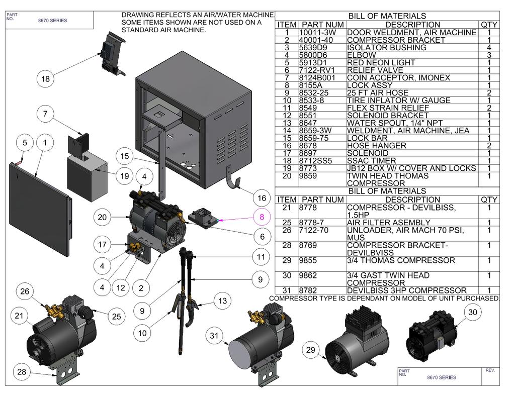
2 TABLE OF CONTENTS PRODUCT INFORMATION... 3 SPECIFICATIONS... 4 IMPORTANT SAFETY INSTRUCTIONS... 5 INSTALLATION INFORMATION GENERAL INFORMATION 5 WIRING INFO... 6 MOUNTING DIMENSIONS 6 TIMER SETUP SSAC SETUP. 7 INFITEC SETUP 8 TIMER SETTINGS CHART. 9 TYPICAL TIMER SETTINGS.. 10 MAINTENANCE PARTS BREAKDOWN AIR MACHINE & WATER.. 12 REEL BASE. 13 SCHEMATICS SERIES WITH SSAC SERIES WITH INFITEC ASCR BASIC TROUBLESHOOTING SERIES MANUAL 3/10/11 2
3 PRODUCT INFORMATION Please take a moment to fill out the information below in order to aid us with any future sales or service inquiries. Model number and serial number information can be found on the serial tag located inside the control box and/or on the lower exterior of the can. Key number can be found on the tag that comes attached to the keys. There may be more than one key number depending on unit. Please keep this information with your records. MODEL#: SERIAL#: KEY NUMBER(S): DATE PURCHASED: DISTRIBUTOR: J.E. Adams Industries rd Ave. S.W. Cedar Rapids, IA
4 SPECIFICATIONS: Unit specifications: Voltage: Amperage: 120v, 60Hz (1) 20 amp service for air/water or air only. (1)10 amp service for air/water or air only Only on units which in include the letters TT OR G in model #. (Example TTA or GA). Do not attempt to hook other models up in this fashion. Instant failure will occur. Weight: lbs with pallet attached Air specifications: Compressor: Dependant on Model # ordered Thomas 120vac@60hz, ¾ hp twin head Thomas 120vac@60hz, ¾ hp- non twin head Devilbiss 120vac@60hz, 1 ½ hp@1725rpm Devilbiss 120vac@60hz, 3hp@3450rpm Gast 120vac@60hz, ¾ hp- twin head Timer: SSAC and Infitec ASCR54 Water specifications: Solenoid: 120vac@60hz NOTE: UNIT INTENDED FOR COMMECIAL USE ONLY Duty cycle: 4 minutes run time- max 4 minutes off time 4
5 IMPORTANT SAFETY INSTRUCTIONS When using an electrical appliance, basic precautions should always be followed, including the following: READ ALL INSTRUCTIONS BEFORE USING (THIS APPLIANCE) WARNING To reduce the risk of fire, electric shock, or injury: Use only as described in manual. Use only manufactures recommended attachments. Do not allow to be used as a toy. Close attention is necessary when used by or near children. Keep hair, loose clothing, fingers, and all parts of body away from openings and moving parts. Never use air nozzle for anything other than for its intended use. Installation Instructions: SAVE THESE INSTRUCTIONS Determine location to mount unit ( DANGER THIS EQUIPMENT INCORPORATES PARTS SUCH AS SWITCHES, MOTORS, OR THE LIKE THAT TEND TO PRODUCE ARCS OR SPARKS THAT CAN CAUSE AN EXPLOSION. WHEN LOCATED IN GASOLINE-DISPENSING AND SERVICE STATIONS INSTALL AND USE AT LEAST 20 FEET (6 M) HORIZONTALLY FROM THE EXTERIOR ENCLOSURE OF ANY DISPENSING PUMP AND AT LEAST 18 INCHES (450 MM) ABOVE A DRIVEWAY OR GROUND LEVEL. Run service to that location Grounding Instructions: This appliance must be connected to a grounded metal, permanent wiring system; or an equipment-grounding conductor must be run with the circuit conductors and connected to the equipment-grounding terminal or lead on the appliance. See next page for bolt pattern. 5
6 AIR MACHINE MOUNTING DIMENSIONS 6
7 TIMER SETUP SSAC TIMERS Note: AE and AN model SSAC timers are accumulating timers. During use, timing can be extended proportionately by adding more coins. The SSAC timer has two adjustable settings: Time per coin (in minutes) and number of coins to start. Time per coin: Time per coin is the amount of time the unit will run per coin inserted and can be set from 0.1 minutes (6 seconds) to 12.7 minutes (12 minutes and 42 seconds) in increments of 6 seconds by turning on the correct switches until their values equal the desired time. Refer to Tables 2 and 3 (pages 11-12) for standard timer and coin settings. For custom settings, follow the steps below: Figure 3: SSAC timer setup Figure 3 shows an SSAC timer set for 1 coin to start and 3.8 minutes per coin for a total run time of 3.8 minutes (3 minutes and 48 seconds). 1. Figure the total time your vac will run (in minutes) and divide that number by the number of coins to start. This is your time per coin. Round up or down to the nearest tenth of a minute. 2. Subtract the largest value switch (initially 6.4) from your time per coin. a. If the resulting number is zero, move the switch to the on position and set all remaining un-set switches in the off position. Your timer is now set. b. If the resulting number is positive, move the switch into the on position. Using the resulting number as your new time per coin, repeat step 2 with the next largest switch value. c. If the resulting number is negative, set the switch in the off position and repeat step 2 using the next largest switch value. Coins to start: Coins to start is the amount of coins needed to activate the timer and can be set from one to seven coins in increments of one coin. Refer to Table 2 (page 10) for switch settings 7
8 TIMER SETUP INFITEC TIMERS The Infitec timer has two adjustable settings: Total run time (in seconds) and number of coins to start. Total run time: Total run time is the amount of time the unit will run once activated and can be set from 1 second to 1023 seconds (17 minutes and 3 seconds) in increments of 1 second by turning on the correct switches until their values equal the desired time. Refer to Tables 2 and 3 (pages 11-12) for standard timer and coin settings. For custom settings, follow the steps below: 1. Figure the total time your vac will run (in seconds). This is your total run time. Round up or down as desired. 2. Subtract the largest value switch (initially 512) from your total run time. a) If the resulting number is zero, move the switch to the on position and set all remaining un-set switches in the off position. Your timer is now set. b) If the resulting number is positive, move the switch into the on position. Using the resulting number as your new time per coin, repeat step 2 with the next largest switch value. c) If the resulting number is negative, set the switch in the off position and repeat step 2 using the next largest switch value. Coins to start: Coins to start is the amount of coins needed to activate the timer and can be set from one to 15 coins in increments of one coin. Refer to Table 2 (page 10) for switch settings. 8
9 IDX Timers: Time Per Coin (In Seconds) Infitec Timers: Total Run Time (In Seconds) (1 min) (2 min) (3 min) (4 min) (5 min) 1 x x x x x x 2 x x x x x x x x x x x x x x x x x x 4 x x x x x x x x x x x x x x x x x x x 8 x x x x x x x x x x x x x x x x x x x 16 x x x x x x x x x x x x x x x x x 32 x x x x x x x x x x x x x x x x x x 64 x x x x x x x x x x x x 128 x x x x x x x x x x x x x 256 x x x x x 512 Time Per Coin (In minutes) 0.1 (6sec) 0.2 (12 sec) 0.3 (18 sec) 0.4 (24 sec) 0.5 (30 sec) 0.6 (36 sec) 0.7 (42 sec) 0.8 (48 sec) 0.9 (54 sec) x x x x x x x x x x x x x x x x x x 0.2 x x x x x x x x x x x x x x x x x x 0.4 x x x x x x x x x x x x x x x x x 0.8 x x x x x x x x x x x x x x x x 1.6 x x x x x x x x x x x x x x 3.2 x x x x x x x 6.4 x x x x x x x x Coins to Start All Timers Coin Switches SSAC Timers Timer Switches Infitec and IDX Timers Timer Switches 1 x x x x x x x x 2 x x x x x x x x 4 x x x x x x x x 8 x x x x x x x x Table 2: Timer Settings Chart Note: X indicates a switch in the on position 9
10 IDX TIMER SETTINGS SSAC TIMER SETTINGS INFITEC TIMER SETTINGS Amount to Start Total Run Time Switches in "On" Position Amount to Start Total Run Time Switches in "On" Position Amount to Start Total Run Time Switches in "On" Position 25 2 MIN 8, 16, 32, MIN 0.4, MIN 8, 16, 32, /2 MIN 2, 4, 16, /2 MIN 0.1, 0.8, /2 MIN 2, 4, 16, MIN 4, 16, 32, MIN 0.2, 0.4, 0.8, MIN 4, 16, 32, /2 MIN 2, 16, 64, /2 MIN 0.1, 0.2, /2 MIN 2, 16, 64, MIN 16, 32, 64, MIN 0.8, MIN 16, 32, 64, /2 MIN 2, 4, 8, /2 MIN 0.1, 0.4, 0.8, /2 MIN 2, 4, 8, MIN 4, 8, 32, MIN 0.2, 1.6, MIN 4, 8, 32, /2 MIN 2, 8, 64, /2 MIN 0.1, 0.2, 0.4, 1.6, /2 MIN 2, 8, 64, MIN 4, 8, 16, MIN 0.2, MIN 8, 16, 32, /2 MIN 4, 8, /2 MIN * /2 MIN 2, 4, 16, MIN 2, 8, 16, MIN 0.1, 0.2, 0.4, MIN 4, 16, 32, /2 MIN 2, 8, 32, /2 MIN * /2 MIN 2, 16, 64, MIN 8, 16, 32, MIN 0.4, MIN 16, 32, 64, /2 MIN 8, /2 MIN * /2 MIN 2, 4, 8, MIN 2, 4, 16, MIN 0.1, 0.8, MIN 4, 8, 32, /2 MIN 2, 4, 32, /2 MIN * /2 MIN 2, 8, 64, MIN 8, MIN * 75 2 MIN 8, 16, 32, /2 MIN 2, 16, /2 MIN * /2 MIN 2, 4, 16, MIN 4, 8, 16, MIN 0.2, MIN 4, 16, 32, /2 MIN 2, 4, /2 MIN * /2 MIN 2, 16, 64, MIN 16, MIN * 75 4 MIN 16, 32, 64, /2 MIN 2, 8, 16, /2 MIN * /2 MIN 2, 4, 8, MIN 4, 32, MIN * 75 5 MIN 4, 8, 32, /2 MIN 2, 4, 8, 32, /2 MIN * /2 MIN 2, 8, 64, 256 $ MIN 2, 4, 8, 16 $ MIN 0.1, 0.4 $ MIN 8, 16, 32, 64 $ /2 MIN 2, 4, 32 $ /2 MIN * $ /2 MIN 2, 4, 16, 128 $ MIN 4, 8, 32 $ MIN * $ MIN 4, 16, 32, 128 $ /2 MIN 2, 4, 16, 32 $ /2 MIN * $ /2 MIN 2, 16, 64, 128 $ MIN 4, 8, 16, 32 $ MIN 0.2, 0.8 $ MIN 16, 32, 64, 128 $ /2 MIN 4, 64 $ /2 MIN * $ /2 MIN 2, 4, 8, 256 $ MIN 4, 8, 64 $ MIN * $ MIN 4, 8, 32, 256 $ /2 MIN 4, 16, 64 $ /2 MIN * $ /2 MIN 2, 8, 64, 256 Table 3: Typical Timer Settings Note: * denotes a configuration that is not possible with this timer. See Table 2 for the closest approximation to this time 10
11 MAINTENANCE Check air nozzle for signs of wear and abuse. Replace as needed. Clean air cabinet as needed with a non abrasive stainless steel cleaner. Examine air hose for cuts or wear and replace as needed. Every month remove filter from compressor and clean. 11
12 12
13 13
14 WATER SOLENOID BLACK TO NO TO B BLACK 8697!! IMPORTANT!! 12 GA BLACK 18GA BLACK ONLY USED WITH UNITS WITH WATER FEATURE *20AMP SERVICE IS REQUIRED FOR DEVILBISS UNITS*!! IMPORTANT!! POWER ON R GA BLACK THOMAS (BROWN) GAST (BLACK) DEVILBISS (BLACK) THOMAS (BLUE) GAST (WHITE) DEVILBISS (WHITE) TO COMPRESSOR *10AMP SERVICE IS REQUIRED FOR TWIN THOMAS & GAST UNITS* 8712SS5 18 GA BLACK ALL COMPRESSORS (GREEN) TO COMPRESSOR OPTIONAL COIN COUNTER 18 GA WHITE FACTORY WIRING FIELD WIRING H A G B F C E D 5914 BLK 120VAC, PART # OPTIONAL CYCLE COUNTER 18 GA BLUE 8124B GA BLUE SWITCH CONNECTIONS ARE THE BLUE WIRES CURRENTLY SHOWN GOING TO THE COIN ACCEPTOR. WHEN SWITCH IS USED COIN ACCEPTOR IS NOT USED. 120 VAC (NEUT) 120 VAC (HOT) 120 VAC (GROUND) 120VAC, PART #
15 8712iD TO 2 TO 3 WATER SOLENOID BLACK BLACK 8697!! IMPORTANT!! POWER ON 18GA BLACK R ONLY USED WITH UNITS WITH WATER FEATURE *20AMP SERVICE IS REQUIRED FOR DEVILBISS UNITS*!! IMPORTANT!! 18GA BLACK THOMAS (BROWN) GAST (BLACK) DEVILBISS (BLACK) THOMAS (BLUE) GAST (WHITE) DEVILBISS (WHITE) TO COMPRESSOR *10AMP SERVICE IS REQUIRED FOR TWIN THOMAS & GAST UNITS* 18 GA BLACK ALL COMPRESSORS (GREEN) TO COMPRESSOR OPTIONAL COIN COUNTER 18 GA WHITE 18 GA BLUE 18 GA BLUE FACTORY WIRING FIELD WIRING H A G B F C E D 5914 BLK 120VAC, PART # OPTIONAL CYCLE COUNTER 8124B001 SWITCH CONNECTIONS ARE THE BLUE WIRES CURRENTLY SHOWN GOING TO THE COIN ACCEPTOR. WHEN SWITCH IS USED COIN ACCEPTOR IS NOT USED. 120 VAC (NEUT) 120 VAC (HOT) 120 VAC (GROUND) 120VAC, PART #
16 TROUBLESHOOTING INFORMATION: STARTS BUT NO PRESSURE SYSTEM LEAKING CHUCK IS CLOGGED UNLOADER PARTS DAMAGED OR WORN OUT. CHECK AIR HOSE FOR LEAKS AND AIR CHUCK. ALSO CHECK FOR LEAKS AROUND COMPRESSOR. CHECK AIR CHUCK TO MAKE SURE NO DEBRIS IS AIR PATH. ALSO CHECK ORING AROUND AIR CHUCK, IS IT BLOCKING THE AIR PATH. IS IT UNLOADING ALL THE TIME? SLEEVE IN COMPRESSOR MAY BE PITTED OR SCRATCHED UP. PISTON ORING MAY BE WORN OR DAMAGED. DEBRIS IN VALVE PLATE OPENING IS NOT ALLOWING IT TO SHUT. REPAIR KIT MAY BE NEEDED. WARNING WARNING Disconnect Power before Servicing Disconnect Power before Servicing 16
Installation Instructions
 50ES, 50EZ, 50GL, 50GS, 50GX, 50JS, 50JX, 50JZ, 50SD, 50SZ, 50VL, 50VT, 50XP, 50XZ 601A, 602A, 602B, 604A, 604B, 604D, 607C, 701A, 702A, 702B, 704A, 704B, 704D, 707C PA1P, PA2P, PA3P, PH1P, PH2P, PH3P
SS91A-M GSM DOOR PHONE (ACCESS CONTROL SYSTEM)
") GAINWISE TECHNOLOGY MANUAL GSM DOOR PHONE SS91A-M GSM DOOR PHONE (ACCESS CONTROL SYSTEM) For your protection, read these instructions completely And keep them for future reference. SS91A-M GSM Door Phone
GAINWISE TECHNOLOGY MANUAL GSM DOOR PHONE SS91A-M GSM DOOR PHONE (ACCESS CONTROL SYSTEM) For your protection, read these instructions completely And keep them for future reference. SS91A-M GSM Door Phone
List of contents. 7-2 CE (ENC EN55022) declaration of conformity CE (LVD EN60950) declaration of conformity. 15 發行章
 declaration of conformity CE (LVD EN60950) declaration of conformity. 15 發行章") S150,S300 Series Pure Sine Wave Inverter User s Manual List of contents 1. IMPORTANT safety Information... 1 1-1 General Safety Precautions.. 1 1-2 Battery Precautions 1 2. Features. 2 2-1 Electrical Performance
S150,S300 Series Pure Sine Wave Inverter User s Manual List of contents 1. IMPORTANT safety Information... 1 1-1 General Safety Precautions.. 1 1-2 Battery Precautions 1 2. Features. 2 2-1 Electrical Performance
Sapling Converter Box
 Installation Manual Sapling Converter Box SCB-100-000-1 Version Number 1.2 Current as of March 15, 2015 The Sapling Company, Inc. (+1) 215.322.6063 P. (+1) 215.322.8498 F. 2-Wire Converter Box (SCB-100-000-1)
SA-150, SA-300 Series Pure Sine Wave Inverter User s Manual
 SA-150, SA-300 Series Pure Sine Wave Inverter User s Manual List of contents 1. IMPORTANT safety Information... 1 1-1 General Safety Precautions.. 1 1-2 Battery Precautions 1 2. Features. 2 2-1 Electrical
User s Manual. ACS550-PD Stock 3R Irrigation Packaged Drive Supplement to ACS550-U1 User s Manual
 User s Manual ACS550-PD Stock 3R Irrigation Packaged Drive Supplement to ACS550-U1 User s Manual 2 ACS550-PD 3R Irrigation Packaged Drive ACS550 Drive Manuals GENERAL MANUALS ACS550-U1 User s Manual (1
High Precision Quad Output DC Power Supply
 User's Guide High Precision Quad Output DC Power Supply Model 382270 Introduction Thank you for selecting the Extech Model 382270. This device is shipped fully tested and calibrated and, with proper use,
SAVE THESE INSTRUCTIONS
 READ AND FOLLOW ALL SAFETY INSTRUCTIONS! SAVE THESE INSTRUCTIONS AND DELIVER TO OWNER AFTER INSTALLATION IMPORTANT SAFEGUARDS! When using electrical equipment, basic safety precautions should always be
Manual. LC-16 system. LC-16 Inkjet Printer 1
 Manual LC-16 system LC-16 Inkjet Printer 1 Index ENVIRONMENT. 3 OPERATOR S SAFETY 3 OPERATION SAFETY 3 PART 1 INSTALLATION AND PARAMETER SETTING 4 1) Preparing 4 2) Installation 4 3) Priming 4 4) Parameter
ELECTRICAL SUPPLY TROUBLESHOOTING QUICK GUIDE SAFETY PRECAUTIONS
 ELECTRICAL SUPPLY TROUBLESHOOTING QUICK GUIDE 1. Circuit Breaker Tripping 2. Circuit Overload 3. Short Circuit 4. Ground Fault 5. Ground Fault Circuit Interrupter (GFCI) Tripping SAFETY PRECAUTIONS Basic
User s Manual. ACS550-PD 3R Irrigation Packaged Drive Supplement to ACS550-U1 User s Manual
 User s Manual ACS550-PD 3R Irrigation Packaged Drive Supplement to ACS550-U1 User s Manual 2 ACS550-PD 3R Irrigation Packaged Drive ACS550 Drive Manuals GENERAL MANUALS ACS550-U1 User s Manual (1 200 HP)
DSS Console and DSS Console for Attendant for Digital Super Hybrid Systems. Reference Guide ANSWER RELEASE
 ANSWER RELEASE PSQX1526ZA 98.8.5 7:32 PM Page 1 DSS Console and DSS Console for Attendant for Digital Super Hybrid Systems Reference Guide Model KX-T7440/KX-T7441 8 16 24 32 40 48 7 15 23 31 39 47 6 14
P216 Series Condenser Fan Speed Controller
 P216 Series Condenser Fan Speed Controller Installation Instructions P216xxx-x Part No. 24-85895-18, Rev. D Issued 27 August 2015 Applications Refer to the QuickLIT website for the most up-to-date version
Electrical Management System (EMS) EMS-HW30C & EMS-HW50C
 EMS-HW30C & EMS-HW50C") Electrical Management System (EMS) EMS-HW30C & EMS-HW50C Installation & Operating Guide for: Model EMS-HW30C Rated at 120V/30A and Model EMS-HW50C Rated at 240V/50A Surgio Says Lifetime Warranty on all
Electrical Management System (EMS) EMS-HW30C & EMS-HW50C Installation & Operating Guide for: Model EMS-HW30C Rated at 120V/30A and Model EMS-HW50C Rated at 240V/50A Surgio Says Lifetime Warranty on all
72In LED Lit Nutcracker Item # CAUTION: IMPORTANT SAFETY INSTRUCTIONS READ AND FOLLOW ALL SAFETY INSTRUCTIONS
 CAUTION: IMPORTANT SAFETY INSTRUCTIONS READ AND FOLLOW ALL SAFETY INSTRUCTIONS FOR INDOOR and OUTDOOR USE The product and its adapter are intended for indoor and outdoor use. When product is used in outdoor
MFA-0801 & MFA-1201 D-M-E Smart Series Low Voltage Temperature Control System. User s Manual. D-M-E Company
 MFA-0801 & MFA-1201 D-M-E Smart Series Low Voltage Temperature Control System User s Manual D-M-E Company D-M-E Company MFA-0801 & MFA-1201 Page 1 Copyright D-M-E Company 1995. All rights reserved. D-M-E
Model P4017 Single Channel USB Oscilloscope. Quick Start Guide
 Model P4017 Single Channel USB Oscilloscope Quick Start Guide General Warranty BNC warrants that the product will be free from defects in materials and workmanship for 3 years from the date of purchase
C-POWER AC AUTOMATIC CONTROL
 Issue 1 Print 1 C-POWER AC AUTOMATIC CONTROL INSTALLATION INSTRUCTIONS & OWNER S MANUAL Model: 93 ACMC100I A Charles Industries, Ltd. All rights reserved. Printed in the United States of America. Issue
User's Guide. Model High Precision Quad Output DC Power Supply
 User's Guide Model 382270 High Precision Quad Output DC Power Supply Introduction Congratulations on your purchase of the Extech 382270 DC Power Supply. The Model 382270 can be used for many applications
Quick Reference Guide
 DSS Console Quick Reference Guide Model No. KX-T7740 Important Information When using the KX-T7740, keep the following in mind. If there is any trouble, disconnect the DSS Console from the telephone line
Series Amp Pad Mount Quick Connect Input and Output Power Panels
 Series 300 2000-4000 Amp Pad Mount Quick Connect Input and Output Power Panels DANGER is used in this manual to warn of a hazard situation which, if not avoided, will result in death or serious injury.
Chore-Tronics IDM Board Instruction
 Chore-Tronics IDM Board Instruction Caution, Warning and Danger Decals have been placed on the equipment to warn of potentially dangerous situations. Care should be taken to keep this information intact
MAKING MODERN LIVING POSSIBLE. Installation Guide. Twin Kit 086L
 MAKING MODERN LIVING POSSIBLE Installation Guide 086L70 www.heating.danfoss.com Danfoss A/S is not liable or bound by warranty if these instructions are not adhered to during installation or service. The
Manual. Water Vend Controller Model ESDI WARNING! ELECTRICAL SHOCK HAZARD! AUTHORIZED PERSONNEL ONLY. EXPOSED 120 VAC ON CIRCUIT BOARD
 Manual Water Vend Controller Model ESDI 030400 WARNING! ELECTRICAL SHOCK HAZARD! AUTHORIZED PERSONNEL ONLY. EXPOSED 120 VAC ON CIRCUIT BOARD THE CIRCUIT BOARD HAS MANY EXPOSED AREAS THAT ARE AT 120 VAC.
Progressive Industries, Inc. EMS Electrical Management System
 Progressive Industries, Inc. EMS Electrical Management System Complete Installation Guide and Operating Instructions for: Model EMS-LCHW50 Rated at 240V/50A Manufactured by: Progressive Industries, Inc.
EMS. Electrical Management System. Progressive Industries Incorporated Morrisville, North Carolina
 Progressive Industries Warranty Progressive warrants its products are free from defects in materials and workmanship for a period of three years. This is in lieu of all other warranties, obligations, or
Wiring Diagrams UNITS WITH STARTING SERIAL NUMBER 3507Q
 AQUASNAP 30RB060-390 Air-Cooled Liquid Chillers with COMFORTLINK Controls 60 Hz Wiring Diagrams UNITS WITH STARTING SERIAL NUMBER 3507Q INDEX* POWER SCHEMATICS 30RB Unit Size Voltage Figure Number Label
Magnum Club Smoke System
 AND INSTALLATION VERSION.0 Martin Professional A/S,Olof Palmes Allé 8, DK-800,Aarhus N Phone: +45 87 40 00 00 Internet: www.martin.dk Magnum Club Smoke System Fluids Suitable for this system: CONNECTIONS
* * Agilent Power Distribution Unit (PDU) Installation Guide
 Installation Guide") Agilent Power Distribution Unit (PDU) Installation Guide For use with Agilent PDU kits and PDU installation kits for Agilent instrument racks June 2008 Edition 7 E0608 *5000-0039* 5000-0039 Notice The
Agilent Power Distribution Unit (PDU) Installation Guide For use with Agilent PDU kits and PDU installation kits for Agilent instrument racks June 2008 Edition 7 E0608 *5000-0039* 5000-0039 Notice The
Instruction Manual. Electrical Management System (EMS) EMS-HW30C & EMS-HW50C
 EMS-HW30C & EMS-HW50C") Instruction Manual Electrical Management System (EMS) EMS-HW30C & EMS-HW50C EMS-HW50C EMS-HW30C! CAUTION These instructions are intended to provide assistance with the installation of this product, and
Instruction Manual Electrical Management System (EMS) EMS-HW30C & EMS-HW50C EMS-HW50C EMS-HW30C! CAUTION These instructions are intended to provide assistance with the installation of this product, and
CAP18 CAP30 U S E R S M A N U A L CONTENTS. 2 Why use a power capacitor? 2 Features. 4 Installation precautions
 CAP8 CAP18 CAP30 8 Farad Super Power Capacitor 18 Farad Super Hybrid Power Capacitor 30 Farad Super Hybrid Power Capacitor page U S E R S M A N U A L CONTENTS 2 Why use a power capacitor? 2 Features 4
VSD-1MC MANUAL 0-10V / 4-20mA Variable Speed Module with Manual Override
 MANUAL 0-10V / 4-20mA Variable Speed Module with Manual Override Varifan 3 4 5 6 7 MANUAL 2 8 1 OFF 10 9 AUTO MANUAL SPEED Installation / User s Guide This guide will inform the electrician on proper wiring
SP6R Level Controller Operation Manual
 SP6R Level Controller Operation Manual www.sjerhombus.com SP6R LEVEL CONTROLLER INTRODUCTION SJE-Rhombus, an industry leader in water and wastewater pump controls, introduces the SP6R Level Controller.
Sidewinder Pumps Inc. AC C1D2 Timer/Controller
 Sidewinder Pumps Inc. AC C1D2 Timer/Controller Page 1 of 14 Rev 4/26/17 Table of Contents 1. Warnings --------------------------------------------------------------------------------------------------
INSTALLATION AND OPERATING INSTRUCTIONS FOR. Serial Control Board SCB-100
 INSTALLATION AND OPERATING INSTRUCTIONS FOR Serial Control Board SCB-100 Important Safety Instructions When using your video equipment, basic safety precautions should always be followed, including the
STC7D. Digital Time Clock for TRC500 & TRC800. Installation, Operation, and Maintenance Manual
 STC7D Digital Time Clock for TRC500 & TRC800 Installation, Operation, and Maintenance Manual READ AND SAVE THESE INSTRUCTIONS The purpose of this manual is to aid in the proper installation and operation
Elapsed Timer Control Panel
 Installation Manual V6.2 Elapsed Timer Control Panel Current as of August 2017 The Sapling Company, Inc. Elapsed Timer Control Panel Table of Contents Table of Contents 2 Important Safety Instructions
CHANNEL LETTER LIGHTING UNIQUE LIGHTING SOLUTIONS RETROFIT INSTALLATION GUIDE
 UNIQUE LIGHTING SOLUTIONS LIGHTING WARNING -Installation must only be performed by a licensed electrician. -To prevent death, injury or damage to property this product must be installed in accordance to
Thread length. 27 (40) mm. 27 (44) mm. 27 (40) mm. 34 (50) mm. 34 (49) mm. 39 (60) mm. 39 (54) mm. 44 (65) mm. 44 (59) mm
 mm. 27 (44) mm. 27 (40) mm. 34 (50) mm. 34 (49) mm. 39 (60) mm. 39 (54) mm. 44 (65) mm. 44 (59) mm") Long Distance Cylindrical. Extra long for increased protection and sensing performance triple proximity sensors for flush mounting requirements. designed and tested for extra long life. Ordering Information
Long Distance Cylindrical. Extra long for increased protection and sensing performance triple proximity sensors for flush mounting requirements. designed and tested for extra long life. Ordering Information
Electrical Management System (EMS) EMS-HW30C & EMS-HW50C
 EMS-HW30C & EMS-HW50C") Electrical Management System (EMS) EMS-HW30C & EMS-HW50C Installation & Operating Guide for: Model EMS-HW30C Rated at 120V/30A and Model EMS-HW50C Rated at 240V/50A Surgio Says Lifetime Warranty on all
Electrical Management System (EMS) EMS-HW30C & EMS-HW50C Installation & Operating Guide for: Model EMS-HW30C Rated at 120V/30A and Model EMS-HW50C Rated at 240V/50A Surgio Says Lifetime Warranty on all
BS 287 DUAL CHANNEL POWER SUPPLY. User Manual. January 2017 V1.0
 BS 287 DUAL CHANNEL POWER SUPPLY User Manual January 2017 V1.0 Table of contents 1.0 SAFETY INSTRUCTIONS... 3 2.0 GENERAL DESCRIPTION PS 289... 4 3.0 MECHANICAL INSTALLATION... 5 4.0 MAINS POWER & SAFETY
SS2200 Remote Controller
 SS2200 Remote Controller General Purpose, DC Voltage General The SS2200 Remote Controller is a microprocessor-based programmable controller specifically designed to control single line and dual line centralized
Configurable Output Distribution. 120V / 208V / 240V 60Hz. User Manual English
 Configurable Output Distribution 120V / 208V / 240V 60Hz User Manual English TABLE OF CONTENTS IMPORTANT SAFETY INSTRUCTIONS.......................... 1 GLOSSARY OF SYMBOLS....................................
Instruction Manual. M Pump Motor Controller. For file reference, please record the following data:
 Instruction Manual M Pump Motor Controller For file reference, please record the following data: Model No: Serial No: Installation Date: Installation Location: When ordering replacement parts for your
Installation and Operating Manual FM50 IOM 2-18 DRAFT
 Installation and Operating Manual Table of Contents 1. Safety Precautions... 3 2. Details 2.1 Part Numbers... 4 2.2 Configurations... 5 2.3 Specifications... 13 2.4 Cables and Wiring... 14 2.5 Interface,
Installation Manual. 1.Included Accessories. System Controller SC-201-6M INT. Requests to Installers *SHA8754 C*
 System Controller SC-201-6M INT Installation Manual Potential dangers from accidents during installation and use are divided into the following two categories. Closely observe these warnings, they are
Model No. ET-JPF200BE
 Operating Instructions Floor Stand Kit Commercial Use Model No. ET-JPF200BE ET-JPF200WE ENGLISH FRANÇAIS ESPAÑOL DEUTSCH ITALIANO * The above illustration is of this product mounted to an optional projector.
VC3000 Series Line Voltage Switching Relay Pack Controllers Installation Guide
 Beyond Comfort VC3000 Series Line Voltage Switching Relay Pack Controllers Installation Guide August 10 th, 2010 (For Commercial and Lodging HVAC Fan Coil Applications) 028-0296-R1-LIT-VC3000-E01 Index
Vortex Series 2-leg Desk Assembly Guide
 ELECTRIC HEIGHT-ADJUSTED SIT TO STAND DESK Vortex Series 2-leg Desk Assembly Guide For desk with underframe Model No. AL4628-XX REV-1509A Table of Contents IMPORTANT SAFETY INSTRUCTIONS... 3 CAUTION, USE
SS91A-M GSM DOOR PHONE (ACCESS CONTROL SYSTEM)
") GAINWISE TECHNOLOGY MANUAL GSM DOOR PHONE SS91A-M GSM DOOR PHONE (ACCESS CONTROL SYSTEM) For your protection, read these instructions completely And keep them for future reference. SS91A-M GSM Door Phone
GAINWISE TECHNOLOGY MANUAL GSM DOOR PHONE SS91A-M GSM DOOR PHONE (ACCESS CONTROL SYSTEM) For your protection, read these instructions completely And keep them for future reference. SS91A-M GSM Door Phone
Control Box Setup - PRSalpha
 888-680-4466 ShopBotTools.com Control Box Setup - PRSalpha Copyright 2016 ShopBot Tools, Inc. page 1 Copyright 2016 ShopBot Tools, Inc. page 2 Parts List: Hooking Up a PRSalpha Gantry Tool Powering the
MicroTech II Remote I/O Panel Installation Manual
 MicroTech II Remote I/O Panel Installation Manual Installation Manual IM 783-2 Group: Controls Part Number: IM 783 Date: November 2006 Supersedes: IM 783-1 Table of Contents Notice... 3 Reference Documents...
USER MANUAL MULTI COLOR TOUCH SCREEN PAPERLESS RECORDER MODEL : ARC2020
 USER MANUAL MULTI COLOR MODEL : ARC2020 ACCSYS ELECTRONICS 140/6B, GOLDEN INDUSTRIAL ESTATE, JAWAHARLAL NEHRU ROAD, GERUGAMBAKKAM, CHENNAI - 600122 Tel: 044 60505599 / 60505511 E-mail : sales@accsyselectronics.com
Removal and Installation8
 8 Screw Types 8-4 Top Cover Assembly 8-5 Left Hand Cover 8-6 Right Hand Cover 8-10 Front Panel Assembly 8-14 Left Rear Cover 8-15 Right Rear Cover 8-16 Extension Cover (60" Model only) 8-17 Media Lever
O P E R A T O R S M A N U A L
 O P E R A T O R S M A N U A L Safety Instructions When using your heat press, basic precautions should always be followed, including the following:.. 3. 4. 5. 6. 7. 8. 9. 0.. Read all instructions. Use
PANEL MOUNT INTERCOMS
 PANEL MOUNT INTERCOMS INSTALLATION AND SERVICE INSTRUCTIONS FOR MODELS AD-26P, AD-27P, AD-56P, and AD-57P Address all communications and shipments to: Electrical Products Division 2645 Federal Signal Drive
SAVE THESE INSTRUCTIONS
 OUTDOOR HARDWIRE INSTALLATION INSTRUCTIONS Please read and save these instructions. Read carefully before using product. Protect yourself and others by observing all safety information, warnings and cautions.
CDD4 Duct Carbon Dioxide Transmitter
 Drill or punch a 1-1/8 or 1-1/4 hole in the duct at the preferred location and insert the probe into the hole to mark the enclosure mounting holes. Remove the unit and drill the four mounting holes. Clean
FHOTON WI-FI MODULE Owner's Manual
 FHOTON WI-FI MODULE Owner's Manual BEFORE GETTING STARTED Read and follow safety instructions. Refer to product data plate(s) for additional operating instructions and specifications. ATTENTION IMPORTANT
OV1000 Part No OV1000 HEIGHT ADJUSTABLE TABLE USER GUIDE
 OV1000 Part No. 23624 OV1000 HEIGHT ADJUSTABLE TABLE USER GUIDE PRODUCT OVERVIEW User Guide: OV1000 OV1000 HEIGHT ADJUSTABLE TABLE A healthier work environment starts with the option to sit or stand throughout
Nature Power Inverters. Modified Sinewave 1000w/1500w True Sinewave 1000w/2000w. Owner s Manual
 Nature Power Inverters Modified Sinewave 1000w/1500w True Sinewave 1000w/2000w Owner s Manual Modified Sinewave Series True Sinewave Series For safe and optimum performance, the Power Inverter must be
PEREGRINE SERIES RETROFIT INSTALLATION GUIDE
 06.05.17 HanleyLED H100W-PPS524V Spec Sheet SOLUTIONS THAT MAKE SENSE PEREGRINE SERIES RETROFIT INSTALLATION GUIDE Light Up New Markets Your Local Distributor: Grimco US www.grimco.com 800.542.9941 Canada
HIGH EFFICIENCY 15 and 17 SEER TWO STAGE HEAT PUMP ENVIRONMENTALLY SOUND R 410A REFRIGERANT. Min. Circuit Ampacity
 ENVIRONMENTALLY SOUND REFRIGERANT C4H(5, 7) Product Specifications HIGH EFFICIENCY 15 and 17 TWO STAGE HEAT PUMP ENVIRONMENTALLY SOUND R 410A REFRIGERANT 2, 3, 4, and 5 TONS SPLIT SYSTEM 208 / 230 Volt,
Operation Manual WARNING. Be sure to read this Operation Manual before use. Universal Space Amusement Equipment Ltd.
 WARNING Be sure to read this Operation Manual before use. Universal Space Amusement Equipment Ltd. CONTENTS 1. The company..2 2. Specifications.. 3 3. Package Contents..5 4. Installation, Fix and Transport..6
Smart Battery Box Owner s Manual & Safety Instructions
 Smart Battery Box Owner s Manual & Safety Instructions PLEASE READ THIS MANUAL BEFORE USE (866)721-0002 www.newportvessels.com support@newportvessels.com Dear Valued Customer, Thank you for purchasing
HV-CS kv Edge Mount Triaxial Jack
 Keithley Instruments 28775 Aurora Road Cleveland, Ohio 44139 1-800-935-5595 http://www.tek.com/keithley HV-CS-1589 3 kv Edge Mount Triaxial Jack Installation Information Description The Keithley Instruments
MT-150. RENOGY 150A Peak High Precision Watt Meter and Power Analyzer E. Philadelphia St., Ontario CA Version: 1.
 MT-150 RENOGY 150A Peak High Precision Watt Meter and Power Analyzer 0 2775 E. Philadelphia St., Ontario CA 91761 1-800-330-8678 Version: 1.1 Important Safety Instructions Please save these instructions.
IMPORTANT SAFETY INSTRUCTIONS
 READ AND FOLLOW ALL SAFETY INSTRUCTIONS SAVE THESE INSTRUCTIONS AND DELIVER TO OWNER AFTER INSTALLATION IMPORTANT SAFETY INSTRUCTIONS WARNING RISK OF SEVERE INJURY OR DEATH To reduce the risk of death,
Series Pressure Sensor Instruction Sheet
 2018/05/10 Series ure Sensor Instruction Sheet Thank you very much for choosing Delta DPA series pressure sensor. Please read this instruction sheet carefully before using your DPA. Keep this instruction
Series Pressure Sensor Instruction Sheet
 Series ure Sensor Instruction Sheet Thank you very much for choosing Delta DPB series pressure sensor. Please read this instruction sheet carefully before using your DPB. Keep this instruction sheet handy
Liebert XDA Air Flow Enhancer. User Manual
 Liebert XDA Air Flow Enhancer User Manual Technical Support Site If you encounter any installation or operational issues with your product, check the pertinent section of this manual to see if the issue
OV1001 Part No OV1001 HEIGHT ADJUSTABLE TABLE USER GUIDE
 OV1001 Part No. 23620 OV1001 HEIGHT ADJUSTABLE TABLE USER GUIDE PRODUCT OVERVIEW User Guide: OV1001 OV1001 HEIGHT ADJUSTABLE TABLE A healthier work environment starts with the option to sit or stand throughout
KOBOLD PDA Series Digital Pressure Transmitter
 KOBOLD PDA Series Digital Pressure Transmitter PDA-153 Series User Instructions KOBOLD Instruments Inc. 1801 Parkway View Drive Pittsburgh, PA 15205 Phone (412) 788-2830 Fax (412)-788-4890 www.koboldusa.com
INSTALLATION INSTRUCTIONS
 INSTALLATION INSTRUCTIONS CONTENT: 1. Important safety instructions 2. Specifications and main dimensions 3. Parts included 4. Control box 5. Installation 6. Adjusting the stroke length of the lift 7.
I/O Expansion Box Installation & Operator s Instruction Manual
 I/O Expansion Box Installation & Operator s Instruction Manual May 2004 CTB Inc. Warranty I/O Expansion Box CTB Inc. Warranty CTB Inc. warrants each new Chore-Tronics product manufactured by it to be free
99 Washington Street Melrose, MA Phone Toll Free Visit us at
 99 Washington Street Melrose, MA 02176 Phone 781-665-1400 Toll Free 1-800-517-8431 Visit us at www.testequipmentdepot.com Table of Contents 1. General Safety Requirements... 1 2. Safety Terms and Symbols...
MAXIMA+ Series Rotary Level Indicator
 MAXIMA+ Series Rotary Level Indicator BinMaster: Division of Garner Industries 7201 N. 98th St., Lincoln, NE 68507 402-434-9102 email: info@binmaster.com www.binmaster.com OPERATING INSTRUCTIONS PLEASE
IntelliBrite Controller (For IntelliBrite Pool, Spa and Landscape Lighting Fixtures) Installation and User s Guide
 Installation and User s Guide") IntelliBrite Controller (For IntelliBrite Pool, Spa and Landscape Lighting Fixtures) Installation and User s Guide *619751* P/N 619751 - Rev B IMPORTANT SAFETY INSTRUCTIONS READ AND FOLLOW ALL INSTRUCTIONS
IntelliBrite Controller (For IntelliBrite Pool, Spa and Landscape Lighting Fixtures) Installation and User s Guide *619751* P/N 619751 - Rev B IMPORTANT SAFETY INSTRUCTIONS READ AND FOLLOW ALL INSTRUCTIONS
PV Rapid Shutdown device
 PV Rapid Shutdown device Installation and Operation Manual Solis-RSD-1G(1:1) Solis-RSD-1G(2:2) Manufacturer: Ginlong (Ningbo) Technologies Co.,Ltd., Ningbo, Zhejiang, P.R.China US Office: 565 Metro Pl.
PRO REMOTE 25 CAPACITANCE PROBE OPERATING INSTRUCTIONS READ THOROUGHLY BEFORE INSTALLING EQUIPMENT Jamieson Equipmen toll free 800
 PRO REMOTE 25 CAPACITANCE PROBE OPERATING INSTRUCTIONS READ THOROUGHLY BEFORE INSTALLING EQUIPMENT TABLE OF CONTENTS GENERAL SPECIFICATIONS...3 1.0 INTRODUCTION...4 2.0 APPLICATIONS...4 3.0 INSTALLATION...4
3-Phase, Dual-Input 6-Slot Power Supply System STARTUP GUIDE
 3-Phase, Dual-Input 6-Slot Power Supply System STARTUP GUIDE -ST-01 Page 1 of 10 November 2016 2016 Copyright Lite-On Technology Corporation ALL RIGHTS RESERVED. Lite-On is a trademark of Lite-On Technology
PLEASE, DON T FORGET YOUR MANUAL!
 Versa-Bale V4 By PSI Waste Equipment Services, Inc. Versa-Bale V4 SUPPORT www.versa-bale.net Phone: 352-742-4774 Fax: 407-992-9389 E-mail or Text: support@versa-pak.net Introduction The purpose of this
Revised: Page 1
 Brought To You By And Designed By: Revised: 2017-05-07 Page 1 Features Of The Universal PSU Kit: Fits all standard Apple II and /// Power Supply Enclosures. (all parts included, user supplies household
Modified Sinewave Series. Power Inverter 1000/1500 MW 1210, MW1215. True Sinewave Power Inverter 1000/2000 SW 1210, SW 1220.
 Modified Sinewave Power Inverter 1000/1500 MW 1210, MW1215 True Sinewave Power Inverter 1000/2000 SW 1210, SW 1220 Owner s Manual Modified Sinewave Series True Sinewave Series 1. INTRODUCTION Thank you
Table of Contents. 3.1 Front/Rear Panel and User Interface Front Panel Rear Panel User Interface...
 General Warranty OWON warrants that the product will be free from defects in materials and workmanship for a period of 2 years (1 year for accessories) from the date of purchase of the product by the original
Installation Instructions for Eaton Surge Protective Device XXCFXXX10-DIN and XXCFXXX10-DIN2
 Supersedes 6/2015 Surge Protective Device XXCFXXX10-DIN and XXCFXXX10-DIN2 XXCFXXX10-DIN Contents Description Page 1.0 Setup...2 1.1 Before Installation...2 1.2 Installation...3 For AC Applications...3
DirectCommand Installation RoGator Model Year Ag Leader Technology
 Note: Indented items indicate parts included in an assembly listed above Part Name/Description Part Number Quantity Direct Command Kit 4100801 1 Dual Lock 2000052-9 1 Dual Lock 2000053-9 1 Quick Reference
E2A. Ordering Information. Cylindrical Proximity Sensor. Safe Mounting with Greater Sensing Distance. E2A Cylindrical Proximity Sensor 1
 Cylindrical Proximity Sensor E2A Safe Mounting with Greater Sensing Distance Ensures a sensing distance approximately 1. to 2 times larger than that of any conventional OMRON Sensor. Problems such as the
ATV Single Row Disc Harrow OWNER S MANUAL
 ATV Single Row Disc Harrow OWNER S MANUAL WARNING: Read carefully and understand all ASSEMBLY AND OPERATION INSTRUCTIONS before operating. Failure to follow the safety rules and other basic safety precautions
SAVE THESE INSTRUCTIONS
 READ AND FOLLOW ALL SAFETY INSTRUCTIS! SAVE THESE INSTRUCTIS AND DELIVER TO OWNER AFTER INSTALLATI IMPORTANT SAFETY INSTRUCTIS WARNING To reduce the risk of death, injury or property damage from fire,
Debitek Card Revalue Station Installation Manual
 Page 1 of 5 Debitek Card Revalue Station Installation Manual General Description The Debitek Card Revalue Station family includes the Cash to Card, Cash to Card with Dispenser, Automatic Debit Machine,
FDS / FDS-R / FDS-PS
 FDS / FDS-R / FDS-PS USER MANUAL For use with 120V 60Hz input. Output is 120V 60Hz at 5amps 600W MAX. switched. ETL LISTED Conforms to UL STD 1241 3091594 79-15167-00 REV. A www.fiberstars.com Page 1 of
9040/9040UK. Users Manual. Phase Rotation Indicator
 9040/9040UK Phase Rotation Indicator Users Manual PN 2438546 April 2005 2005 Fluke Corporation. All rights reserved. Printed in China All product names are trademarks of their respective companies. LIMITED
MOBILE CONNECTOR - GEN 2 OWNER'S MANUAL
 MOBILE CONNECTOR - GEN 2 OWNER'S MANUAL UNITED STATES Contents Safety Information... 2 Save These Important Safety Instructions... 2 Warnings...2 Cautions...3 General Information... 4 Mobile Connector
MAXIMA + Series ROTARY LEVEL CONTROL
 Price $5.00 MAXIMA + Series ROTARY LEVEL CONTROL OPERATING INSTRUCTIONS PLEASE READ CAREFULLY Division of Garner Industries 7201 North 98th Street Lincoln, NE 68507-9741 (402) 434-9102 925-0268 Rev. A
Rotork Fairchild PAX1 Linear Actuator User s Manual
 Rotork Fairchild PAX1 Linear Actuator User s Manual Product Overview The PAX1 is a flexible low voltage DC powered linear actuator featuring a 5 mm maximum thrust rod stroke moving at speeds up to 0 mm/min
15 channel programmable event timer, with RPM and Pressure inputs. *With Tachometer Feature
 ELECTRIMOTION INC. 144 DALE FORD RD. DELAWARE, OH 43015 740.362.0251 15 channel programmable event timer, with RPM and Pressure inputs. *With Tachometer Feature Power Input connector: 2 pin plug (red-black)
PRO REMOTE 25 LV CAPACITANCE PROBE
 Price $5.00 PRO REMOTE 25 LV CAPACITANCE PROBE OPERATING INSTRUCTIONS READ THOROUGHLY BEFORE INSTALLING EQUIPMENT TABLE OF CONTENTS GENERAL SPECIFICATIONS...3 1.0 INTRODUCTION...4 2.0 APPLICATIONS...4
IMPULSE G2/PULSE HEIGHT ADJUSTABLE TABLE LIFTING COLUMN: DL17 CONTROL: DPF1C CONTROL BOX: CBD6S PART # CONTROL MECHANISM OVERVIEW PAGE 1 OF 6
 PART # 1608996 LIFTING COLUMN: DL17 CONTROL: DPF1C CONTROL BOX: CBD6S PAGE 1 OF 6 CONTROL BOX WIRING DIAGRAM Hook for cable relief DL17 DL17 DPF1C Mains Cable BASIC HEIGHT ADJUSTABLE FUNCTIONS RAISING
BS 181 SINGLE CHANNEL POWER SUPPLY USER MANUAL
 BS 181 SINGLE CHANNEL POWER SUPPLY USER MANUAL August 2016 This product is designed and manufactured by: ASL Intercom B.V. Zonnebaan 42 3542 EG Utrecht The Netherlands Phone: +31 (0)30 2411901 Fax: +31