JumperFree TM CUA
|
|
|
- Vincent McKenzie
- 5 years ago
- Views:
Transcription
1 JumperFree TM CUA
2 2 2000
3 3
4 4
5 5
6 6
7 7
8 8
9 9
10 10
11 11
12 3D Graphics 12


13
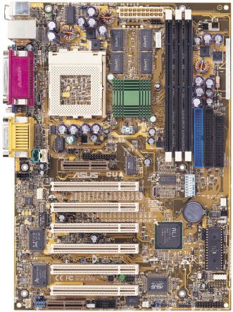
14 21.3 cm (8.38 in) PS/2KBMS VIO USB 2MB SDRAM IC_ PWR_ FAN COM2 2MB SDRAM 2MB SDRAM 2MB SDRAM CPU_ FAN JTPWR VGA Socket 370 CD1 VIDEO AUX BS133 JTCPU VMI CUA Row (DSW1) DIP Switches CHA_FAN 30.5 cm (12.0 in) SMB LANEN LANPWR Clear RTC (R242) USBPWR LED1 USBPORT SPDIFOUT AUDIOEN Audio Codec Setting WOL COM2 WOR JEN RT1 CHASSIS IR_CON IDELED PANEL 14
15 15
16 16
17 PLED2 CUA ON Standby Power OFF Powered Off CUA Onboard LED 17
18 CUA DSW1 ON CUA DIP Switches OFF 1: Frequency Selection 2: Frequency Selection 3: Frequency Selection 4: Frequency Selection 5: Frequency Multiple 6: Frequency Multiple 7: Frequency Multiple 8: Frequency Multiple DSW1 ON CUA OFF Jumper 1 2 JEN JumperFree (Default) 2 3 CUA JumperFree Mode Setting 18
19 CUA SPK ADN# AUD_EN1 AUD_EN2 SPK ADN# AUD_EN1 AUD_EN2 CUA Audio Codec Setting Enable Disable (Default) 19
20 CUA USBPWR 1 +5VSB 2 2 (Default) +5V 3 (Default) CUA USB Power Source 20
21 VIO Normal (Default) Reserved CUA CUA Input/Output Voltage Setting CUA BS Normal (Default) CUA Bus Selection 21
22 ON ON ON CPU 66MHz PCI 33MHz 68MHz 34MHz 75MHz 37.5MHz 80MHz 40MHz ON ON ON ON ON CPU 83MHz PCI 41.6MHz 100MHz 33MHz 103MHz 34.3MHz 105MHz 35MHz CUA ON CPU 110MHz PCI 36.6MHz ON MHz 37.3MHz ON MHz 38.3MHz ON MHz 40MHz CUA CPU External CPU 124MHz Clock (BUS) Frequency Selection PCI 31MHz ON ON ON MHz (JumperFree Mode) 140MHz 33MHz 35MHz ON MHz 37.5MHz 22
23 ON x(3/2) ON x2(2/1) ON x(2/1) ON x(5/2) ON x(3/1) CUA ON x(7/2) ON x(4/1) ON x(9/2) ON x(5/1) ON x(11/2) CUA CPU BUS Frequency Multiple ON x(6/1) ON x(13/2) ON x(7/1) ON x(15/2) ON x(8/1) Pentium III 933MHz 7.0x 133MHz [OFF][OFF][OFF][OFF] [ON] [OFF] [ON] [OFF] Pentium III 866MHz 6.5x 133MHz [OFF][OFF][OFF][OFF] [OFF] [ON] [ON] [OFF] Pentium III 800MHz 6.0x 133MHz [OFF][OFF][OFF][OFF] [ON] [ON] [ON] [OFF] Pentium III 733MHz 5.5x 133MHz [OFF][OFF][OFF][OFF] [OFF][OFF][OFF] [ON] Pentium III 667MHz 5.0x 133MHz [OFF][OFF][OFF][OFF] [ON] [OFF][OFF] [ON] Pentium III 600MHz 4.5x 133MHz [OFF][OFF][OFF][OFF] [OFF] [ON] [OFF] [ON] Pentium III 533MHz 4.0x 133MHz [OFF][OFF][OFF][OFF] [ON] [ON] [OFF] [ON] Pentium III 800MHz 8.0x 100MHz [OFF][OFF][OFF] [ON] [ON] [ON] [OFF][OFF] Pentium III 750MHz 7.5x 100MHz [OFF][OFF][OFF] [ON] [OFF][OFF] [ON] [OFF] Pentium III 700MHz 7.0x 100MHz [OFF][OFF][OFF] [ON] [ON] [OFF] [ON] [OFF] Pentium III 650MHz 6.5x 100MHz [OFF][OFF][OFF] [ON] [OFF] [ON] [ON] [OFF] Pentium III 600MHz 6.0x 100MHz [OFF][OFF][OFF] [ON] [ON] [ON] [ON] [OFF] Pentium III 550MHz 5.5x 100MHz [OFF][OFF][OFF] [ON] [OFF][OFF][OFF] [ON] Pentium III 500MHz 5.0x 100MHz [OFF][OFF][OFF] [ON] [ON] [OFF][OFF] [ON] Pentium III 450MHz 4.5x 100MHz [OFF][OFF][OFF] [ON] [OFF] [ON] [OFF] [ON] Celeron 533MHz 8.0x 66MHz [OFF][OFF] [ON] [ON] [ON] [ON] [OFF][OFF] Celeron 500MHz 7.5x 66MHz [OFF][OFF] [ON] [ON] [OFF][OFF] [ON] [OFF] Celeron 466MHz 7.0x 66MHz [OFF][OFF] [ON] [ON] [ON] [OFF] [ON] [OFF] Celeron 433MHz 6.5x 66MHz [OFF][OFF] [ON] [ON] [OFF] [ON] [ON] [OFF] Celeron 400MHz 6.0x 66MHz [OFF][OFF] [ON] [ON] [ON] [ON] [ON] [OFF] Celeron 366MHz 5.5x 66MHz [OFF][OFF] [ON] [ON] [OFF][OFF][OFF] [ON] Celeron 333MHz 5.0x 66MHz [OFF][OFF] [ON] [ON] [ON] [OFF][OFF] [ON] Celeron 300MHz 4.5x 66MHz [OFF][OFF] [ON] [ON] [OFF] [ON] [OFF] [ON] Celeron 266MHz 4.0x 66MHz [OFF][OFF] [ON] [ON] [ON] [ON] [OFF] [ON] 23
24 24
25 Lock 20 Pins 60 Pins CUA 88 Pins CUA 168-Pin DIMM Sockets 168-Pin DIMM Notch Key Definitions (3.3V) DRAM Key Position RFU Unbuffered Buffered Voltage Key Position 5.0V Reserved 3.3V 25
26 Socket 370 (Top) Socket 370 (Bottom) Celeron CUA Notch Pentium III CUA Socket 370 Gold Arrow 26
27 27
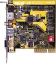
28 CUA To install the AMR card, face its components toward the serial ports. CUA Audio Modem Riser Connector 28


29 CUA CUA TV/LCD Slot 29
30 30
31 PS/2 Mouse (6-pin female) PS/2 Keyboard (6-pin female) 31
32 USB 1 Universal Serial Bus (USB) 2 Parallel (Printer) Port (25-pin female) VGA Monitor (15-pin female) 32
33 PIN COM 1 Serial Port (9-pin male) CUA 1 CUA Serial COM2 Bracket Line Out Line In Mic 1/8" Stereo Audio Connectors 33
34 Joystick/MIDI (15-pin female) CUA Secondary IDE Connector Primary IDE Connector NOTE: Orient the red markings (usually zigzag) on the IDE ribbon cable to PIN 1. CUA IDE Connectors PIN 1 34
35 FLOPPY CUA NOTE: Orient the red markings on the floppy ribbon cable to PIN 1. PIN 1 CUA Floppy Disk Drive Connector 1 13 CUA CUA Feature (VMI) Connector 35
36 1 IR Front View Back View CUA +5V IRRX GND IRTX IRTX GND IRRX +5V (NC) CUA Infrared Module Connector +3.3 Volts Volts Ground Power Supply On Ground Ground Ground -5.0 Volts +5.0 Volts +5.0 Volts CUA CUA ATX Power Connector +3.3 Volts +3.3 Volts Ground +5.0 Volts Ground +5.0 Volts Ground Power Good +5V Standby Volts 36
37 GND +12V Rotation GND +12V Rotation IC_PWR_FAN CPU_FAN CUA Rotation +12V CHA_FAN GND CUA 12-Volt Cooling Fan Power CHASSIS 1 CUA Ground Chassis Signal +5Volt (Power Supply Stand By) CUA Chassis Open Alarm Lead 37
38 CUA +3V 5V SMBDATA Ground 1 SMBCLK SMB CUA SMBus Connector CUA CUA USB Header USB Power USBP2 USBP2+ GND NC 1 5 USBPORT 6 10 USB Power USBP3 USBP3+ GND 38
39 IMPORTANT: Requires an ATX power supply with at least 720mA +5 volt standby power CUA WOL Ground CUA Wake-On-LAN Connector PME +5 Volt Standby CUA WOR 2 1 Ring# Ground A7V Wake-On-Ring Connector 39
40 CD1 CUA VIDEO (Green) (Black) AUX (White) Left Audio Channel Ground Right Audio Channel Left Audio Channel Ground Right Audio Channel CUA Internal Audio Connectors CUA TIP: If the case-mounted LED does not light, try reversing the 2-pin plug. IDELED CUA IDE Activity LED 40
41 Ground Power LED +5 V PLED Speaker Connector +5V Ground Ground Speaker CUA CUA System Panel Connectors Message LED SMI Lead +5 V TB_LED ExtSMI# Ground PWR +3VSB Reset Ground Reset SW ATX Power Switch* * Requires an ATX power supply. 41
42 42
43 43
44 44


45 45


46 46


47 47
48 48
49 49
50 <F1> or <Alt + H> <Esc> or<alt + X> or (keypad arrow) or (keypad arrows) - (minus key) + (plus key) or spacebar <Enter> <Home> or <PgUp> <End> or <PgDn> <F5> <F10> 50
51 51

52 52


53 53


54 54
55 55


56 56
57 CUA CUA Clear RTC RAM BIOS EEPROM R242 C242 R243 Short solder points to Clear CMOS 57


58 58
59 59


60 60
![[2T] [3T]](/docs-images/94/121650355/images/61-18.jpg "[7T] [6T]")


61 [2T] [3T] [7T] [6T] 61
62 62


63 63
64 64


65 65
66 66


67 67


68 68
69 69


70 70
71 71


72 72


73 73
74 74


75 75
76 76
77 77


78 78
79 79


80 80


81 81


82 82


83 83


84 84
85 85


86 86


87 87


88 88
89 89


90 90
91 91


92 92


93 93


94 94


95 95


96 96


97 97


98 98


99 TIPS! 99
100 100

 0 1 Z=0.")

101 Beetle Crazy Cup is copyright 2000 by INFORGRAMES Original idea and development by XPIRAL (Efecto Caos S.L.) 0 1 Z=0.0 E Embossment Z=1.0 Number of vertices on this Z-value 101
CUV4X. JumperFree TM PC-133 AGP/4X
 CUV4X JumperFree TM PC-133 AGP/4X 2 2000 3 4 5 6 7 8 9 10 11 12 1 2 3 4 5 6 7 25 24 23 22 21 20 19 18 17 16 15 14 13 12 11 10 9 8 13 20.9cm (8.22in) PS/2 VIO CPU_FAN Socket 370 cyrix 133 VIA VT82C694X
CUV4X-E. JumperFree TM PC-133/VC MHz FSB AGP PRO/4X Socket 370
 CUV4X-E JumperFree TM PC-133/VC133 133MHz FSB AGP PRO/4X Socket 370 2 2000 3 4 5 6 7 8 9 10 11 12 1 2 3 4 567 8 24 23 22 21 20 19 18 17 16 15 14 13 12 11 10 9 13 20.9cm (8.22in) PS/2 VIO USB COM1 LED Socket
A7PRO. Jumper TM PC133/VC MHz FSB AGP Pro/4X
 A7PRO Jumper TM PC133/VC133 200MHz FSB AGP Pro/4X 2000 2 3 4 5 6 7 8 9 10 11 / 12 1 2 3 4 5 6 7 8 25 24 23 22 21 20 19 18 17 16 15 14 13 12 11 10 9 13 24.5cm (9.64in) PS/2 JTPWR PWR_FAN VIO USB COM1 Socket
A7A266-E DDR RAM/SDRAM 266MHz FSB AGP Pro/4X Socket A
 A7A266-E DDR RAM/SDRAM 266MHz FSB AGP Pro/4X Socket A 2 2001 3 4 5 6 7 8 9 10 11 / 12 1 2 3 4 5 6 7 27 26 25 24 23 22 21 20 19 18 17 16 15 14 131211 109 8 13 24.5cm (9.64in) PS/2 CPU_FAN USB1 USB2 01 01
2 2001
 CUV266 Socket 370 2 2001 3 4 5 6 7 8 9 10 11 12 1 2 3 4 5 6 27 26 25 24 23 22 21 20 19 18 17 1615 14 13 1211109 8 7 13 24.5cm (9.64in) PS/2 USB1_PWR CUV266 USB RJ-45 COM1 JTPWR 0 1 01 3 4 01 01 5 6 VIO3
P4T533-C
 P4T533-C T1047 2002 ii iii iv v vi vii viii 1 2 2 3 Jumper Mode Jumper Free (Default) ix x xi xii 1 2 3 4 1 23 4 5 6 7 32 31 30 29 28 27 26 25 24 23 8 9 10 11 12 13 14 22 21 20 19 18 17 16 15 33 34 35
P4G8X P4G8X Deluxe P4G8X
 P4G8X P4G8X Deluxe P4G8X Motherboard T1133 2002 2 3 4 5 6 7 8 1 2 2 3 Jumper Mode Jumper Free (Default) 9 10 11 12 1-1 1-2 1-3 1-4 1-5 1-6 1 2 3 4 5 6 7 8 21 20 19 9 10 18 17 16 1514 13 12 11 22 23 24
P4B533-E. Motherboard
 P4B533-E Motherboard T986 2002 2 3 4 5 6 7 8 1 2 2 3 Jumper Mode Jumper Free (Default) 9 10 11 12 1-1 1-2 1-3 1-4 1-5 1-6 1 2 3 4 5 6 7 23 22 8 9 10 21 20 11 12 19 13 18 17 16 15 14 24 25 26 27 28 29
K1140A. December Checklist. Copyright 2002 ASUSTeK COMPUTER INC. All Rights Reserved.
 P4PE Motherboard Checklist K1140A December 2002 Copyright 2002 ASUSTeK COMPUTER INC. All Rights Reserved. ii Contents Features iii Safeguards Contents iv Contents v vi vii viii ix x P4PE xi xii P4PE Chapter
A7V8X-MX. Motherboard
 A7V8X-MX Motherboard T1397 2003 ii iii iv v vi A7V8X-MX-TAYZ 10839 11036 6 0 12XX56XX90 vii viii ix x 1-1 1-2 TM 1 2 3 4 5 6 7 8 14 13 9 10 12 11 15 16 17 18 19 20 25 24 23 22 21 1-3 1-4 1-5 24.5cm (9.6in)
6SMM7 USER'S MANUAL. Celeron TM Socket 370 Processor MAINBOARD REV. 1.1 First Edition R
 USER'S MANUAL. System power on by Keyboard: If your ATX power supply supports larger than 00 ma 5V Stand-By current (dependent on the specification of keyboards), you can power on your system by entering
1. FEATURES. 1.1 The CUW-AM
 Specifications 1. FEA TURES 1. FEATURES 1.1 The The motherboard is carefully designed for the demanding PC user who wants advanced features processed by the fastest processors. 1.1.1 Specifications Latest
CLK. Slot1 VIA ATX Mainboard. User s Manual 4
 2.1. Mainboard Layout Drawing CLK AGP 1 H14.318 Slot1 VIA693-133 ATX Mainboard ISA2 ISA1 User s Manual 4 2.2. Hardware Installation Steps 2.2.1. Installing System Memory The mainboard is equipped with
2. FEATURES. 2.1 The CUV-NT
 Specifications 2. FEA TURES 2. FEATURES 2.1 The The motherboard is carefully designed for the demanding PC user who wants advanced features processed by the fastest processors. 2.1.1 Specifications Latest
P4B533-X. Motherboard
 P4B533-X Motherboard C1458 2003 2 3 4 5 6 7 1 2 2 3 Jumper Mode Jumper Free (Default) 8 9 10 1-1 1-2 1-3 1-4 SB_PWR1 P4B533-X P4B533-X Onboard LED ON Standby Power OFF Powered Off 1-5 CPU_FAN1 ATX12V1
6BA USER'S MANUAL. For Intel Pentium II / III / Celeron Processor MAINBOARD REV. 3.0 First Edition R
 USER'S MANUAL. System power on by PS/2 Mouse: First, enable this function in CMOS Setup, then you can power on the system by double clicking the right or left button of your PS/2 Mouse. 2. System power
Chapter 2 HARDWARE INSTALLATION. 2.1 Central Processing Unit: CPU CHAPTER 2
 Chapter 2 HARDWARE INST 2.1 Central Processing Unit: CPU The mainboard operates with Intel Pentium II/Celeron TM processor. The mainboard uses a CPU Slot called Slot 1 for easy CPU installation and a jumper
1. FEATURES. 1.1 The A7V-VM Motherboard
 1. FEATURES 1.1 The Motherboard The motherboard is carefully designed for the demanding PC user who wants high-performance features in a small package. 1.1.1 Specifications AMD Athlon /Duron Processor
P4V800-X. Motherboard
 P4V800-X Motherboard C1371 2003 2 3 4 5 6 TM 1 2 2 3 Jumper Mode Jumper Free (Default) 7 8 9 10 1-1 1-2 1-3 1 2 3 4 5 6 16 8 7 15 14 13 9 10 12 17 11 18 19 20 21 22 27 26 25 24 23 1-4 1-5 1-6 1-7 19.3cm
6BMM USER'S MANUAL. 3. Support Modem Ring-On. (Include internal Modem and external modem on COM A and COM B)
") USER'S MANUAL. System power on by PS/2 Mouse: First, enable this function in CMOS Setup, then you can power on the system by double clicking the right or left button of your PS/2 Mouse. 2. System power
USER'S MANUAL. System power on by PS/2 Mouse: First, enable this function in CMOS Setup, then you can power on the system by double clicking the right or left button of your PS/2 Mouse. 2. System power
686BX USER'S MANUAL. 3. Supports 3 steps ACPI LED. 4. Modem Ring-On. (COM B) 5. Wake-Up on LAN. (on J13) 6. Supports LDCM
 5. Wake-Up on LAN. (on J13) 6. Supports LDCM") 686BX USER'S MANUAL. System power on by PS/2 Mouse: First, enable this function in CMOS Setup, then you can power on the system by double clicking the right or left button of your PS/2 Mouse. 2. System
686BX USER'S MANUAL. System power on by PS/2 Mouse: First, enable this function in CMOS Setup, then you can power on the system by double clicking the right or left button of your PS/2 Mouse. 2. System
MEL Socket 370 Motherboard USER S MANUAL
 R MEL Socket 370 Motherboard USER S MANUAL USER'S NOTICE No part of this manual, including the products and software described in it, may be reproduced, transmitted, transcribed, stored in a retrieval
P4P800-X. Motherboard
 P4P800-X Motherboard 2 C1718 3 4 5 6 1 2 2 3 Jumper Mode Jumper Free (Default) 7 8 9 10 1-1 1-2 1-3 SB_PWR P4P800-X P4P800-X Onboard LED ON Standby Power OFF Powered Off 1-4 20.8cm (8.2in) CPU_FAN ATX12V
Chapter 1 Specification
 SL-I / I-L Chapter Specifications COM LPT Chapter Specification - Mainboard Layout and Components Setup CPU Fan Analog Monitor Front Audio CD-ROM Audio LAN Controller (for I-L) ne in CD AC'97 IT872F JKB
CUW-RM Intel 810 microatx Motherboard USER S MANUAL
 CUW-RM Intel 810 microatx Motherboard USER S MANUAL USER'S NOTICE No part of this manual, including the products and software described in it, may be reproduced, transmitted, transcribed, stored in a retrieval
TABLE OF CONTENTS 1. INTRODUCTION 2. SPECIFICATION 3. HARDWARE INSTALLATION 6BA
 6BA TABLE OF CONTENTS 1. INTRODUCTION 1.1. PREFACE...1-1 1.2. KEY FEATURES...1-1 1.3. PERFORMANCE LIST...1-2 1.4. BLOCK DIAGRAM...1-3 1.5. INTRODUCE THE Pentium II / III Processor...1-4 1.6. What is AGP?...1-5
Quick Start Guide. SY-6BB V1.0 Mainboard F C. Introduction. Installation. Hardware. Quick BIOS Setup. The SOYO CD
 SY-6BB V.0 Mainboard Quick Start Guide Introduction Hardware Installation Quick BIOS Setup The SOYO CD F C Tested To Comply With FCC Standards FOR HOME OR OFFICE USE POST CONSUMER 00% RECYCLED PAPER SOYO
X533. User Manual. Version 1.0 Published April 2003 Copyright 2003 ASRock INC. All rights reserved.
 X533 User Manual Version 1.0 Published April 2003 Copyright 2003 ASRock INC. All rights reserved. 1 Copyright Notice: No part of this manual may be reproduced, transcribed, transmitted, or translated in
TABLE OF CONTENTS 1. INTRODUCTION 2. SPECIFICATION 3. HARDWARE INSTALLATION. Table of Contents 1.1. PREFACE KEY FEATHERS...
 Table of Contents TABLE OF CONTENTS 1. INTRODUCTION 1.1. PREFACE... 1-1 1.2. KEY FEATHERS... 1-1 1.3. PERFORMANCE LIST... 1-2 1.4. BLOCK DIAGRAM... 1-3 1.5. INTRODUCE THE PENTIUM II/ III PROCESSORS...
M266A. User Manual. Version 1.0 Published April 2003 Copyright 2003 ASRock INC. All rights reserved.
 M266A User Manual Version 1.0 Published April 2003 Copyright 2003 ASRock INC. All rights reserved. 1 Copyright Notice: No part of this manual may be reproduced, transcribed, transmitted, or translated
P4PE2-X. Motherboard
 P4PE2-X Motherboard C1788 2004 2 3 4 5 6 7 1 2 2 3 Jumper Mode Jumper Free (Default) 8 9 10 1-1 1-2 1-3 SB_PWR P4PE2-X P4PE2-X Onboard LED ON Standby Power OFF Powered Off 1-4 CPU_FAN ATX12V SPDIF_O COM1
TABLE OF CONTENTS 1. INTRODUCTION 2. SPECIFICATION 3. HARDWARE INSTALLATION 6BMM 1.1. PREFACE KEY FEATURES...1-1
 6BMM TABLE OF CONTENTS 1. INTRODUCTION 1.1. PREFACE...1-1 1.2. KEY FEATURES...1-1 1.3. PERFORMANCE LIST...1-2 1.4. BLOCK DIAGRAM...1-3 1.5. INTRODUCE THE Pentium II Processor & AGP...1-4 1.6. What is AGP?...1-6
TABLE OF CONTENTS 1. INTRODUCTION 2. SPECIFICATION 3. HARDWARE INSTALLATION 6LX7 / 6LX7A 1.1. PREFACE KEY FEATHERS...
 TABLE OF CONTENTS 1. INTRODUCTION 1.1. PREFACE...1-1 1.2. KEY FEATHERS...1-1 1.3. PERFORMANCE LIST...1-3 1.4. BLOCK DIAGRAM...1-4 1.5. INTRODUCE THE INTEL Celeron TM Socket 370 Processor...1-5 1.6. WHAT
TABLE OF CONTENTS 1. INTRODUCTION 2. SPECIFICATION 3. HARDWARE INSTALLATION 6VX PREFACE KEY FEATHERS
 6VX7 TABLE OF CONTENTS 1. INTRODUCTION 1.1. PREFACE... 1-1 1.2. KEY FEATHERS... 1-1 1.3. PERFORMANCE LIST... 1-2 1.4. BLOCK DIAGRAM... 1-3 1.5. INTRODUCE THE INTEL Celeron TM Socket 370 Processor... 1-4
5AMMC USER'S MANUAL. Support Intel Pentium, MMX, Cyrix/IBM 6x86MX, MII, AMD K5, K6, K6-2 & IDT C6 CPUs. Support auto detect CPU Voltage.
 5AMMC USER'S MANUAL Support Intel Pentium, MMX, Cyrix/IBM 6x86MX, MII, AMD K5, K6, K6-2 & IDT C6 s. Support auto detect Voltage. Support Parity check or Ecc Function. Support Fully.0 Specification. Support
P4S800D-X. Motherboard
 P4S800D-X Motherboard T1753 2004 2 3 4 5 P4S800D-X-TAYZ 6 10839 11036 0 11XX11XX11 6 7 8 1-1 1-2 1-3 SB_PWR1 P4S800D-X P4S800D-X Onboard LED ON Standby Power OFF Powered Off 1-4 R 24.5cm (9.6in) PWR_FAN1
TABLE OF CONTENTS 1. INTRODUCTION 2. SPECIFICATION 3. HARDWARE INSTALLATION. Table Of Contents 1.1. PREFACE KEY FEATURES...
 Table Of Contents TABLE OF CONTENTS 1. INTRODUCTION 1.1. PREFACE...1-1 1.2. KEY FEATURES...1-1 1.3. PERFORMANCE LIST...1-2 1.4. BLOCK DIAGRAM...1-3 1.5. INTRODUCE THE Pentium II Processor & AGP...1-4 1.6.
K7V Slot A Motherboard USER S MANUAL
 R K7V Slot A Motherboard USER S MANUAL USER'S NOTICE No part of this manual, including the products and software described in it, may be reproduced, transmitted, transcribed, stored in a retrieval system,
PCIE-Q670-R20 Quick Installation Guide Version 2.01
 Full-size PICMG 1.3 CPU Card supports LGA1155 Intel, Intel Core i7/i5/i3/pentium and Celeron processor CPU per Intel Q67, DDR3, VGA /DVI-D, Dual Intel PCIe GbE, SATA 6Gb/s, mini PCIe, HD Audio and RoHS
TABLE OF CONTENTS 1. INTRODUCTION 1.1. PREFACE KEY FEATURES PERFORMANCE LIST BLOCK DIAGRAM...
 TABLE OF CONTENTS 1. INTRODUCTION 1.1. PREFACE... 1-1 1.2. KEY FEATURES... 1-1 1.3. PERFORMANCE LIST... 1-3 1.4. BLOCK DIAGRAM... 1-4 1.5. INTRODUCE THE PCI - BUS... 1-5 1.6. FEATURES... 1-5 2. SPECIFICATION
CUSL-L. Intel 815 microatx Motherboard USER S MANUAL
 Intel 815 microatx Motherboard USER S MANUAL USER'S NOTICE No part of this manual, including the products and software described in it, may be reproduced, transmitted, transcribed, stored in a retrieval
PE Pro-HT. User Manual. Version 1.0 Published January 2003 Copyright 2003 ASRock INC. All rights reserved.
 PE Pro-HT User Manual Version 1.0 Published January 2003 Copyright 2003 ASRock INC. All rights reserved. 1 Copyright Notice: No part of this manual may be reproduced, transcribed, transmitted, or translated
Introduction CHAPTER 1
 CHAPTER 1 Introduction The ROBO-667 all-in-one single board computer is designed to fit a high performance Pentium-III based CPU and compatible for high-end computer system with PCI/ISA Bus architecture.
User s Manual Full-Size PICMG 1.3 SHB Version 1.0
 3308360 User s Manual Full-Size PICMG 1.3 SHB Version 1.0 Copyrights This document is copyrighted and all rights are reserved. It does not allow any non authorization in copied, photocopied, translated
Assignment 5. You can configure hardware options by setting jumper on the mainboard. See Figure 2-1 for jumper locations. Set a jumper as follows:
 CIS 170 Microcomputer Hardware Name: Assignment 5 From the lack of having enough peripherals for this course (at least at this point), we have the necessity of doing some experiments mentally rather than
6BXC USER'S MANUAL. 3. Supports 3 steps ACPI LED. 4. Modem Ring-On. (COM A, B).
.") USER'S MANUAL. System power on by PS/2 Mouse: First, enable this function in CMOS Setup, then you can power on the system by double clicking the right or left button of your PS/2 Mouse. 2. System power
USER'S MANUAL. System power on by PS/2 Mouse: First, enable this function in CMOS Setup, then you can power on the system by double clicking the right or left button of your PS/2 Mouse. 2. System power
CUW(E)-FX Intel 810 FlexATX Motherboard USER S MANUAL
-FX Intel 810 FlexATX Motherboard USER S MANUAL") CUW(E)-FX Intel 810 FlexATX Motherboard USER S MANUAL Special Features CUWE-FX Intel 810E Chipset with support for 133/100/66MHz FSB 4MB 32-bit 133MHz SDRAM display cache onboard CUW-FX Intel 810 Chipset
CUW(E)-FX Intel 810 FlexATX Motherboard USER S MANUAL Special Features CUWE-FX Intel 810E Chipset with support for 133/100/66MHz FSB 4MB 32-bit 133MHz SDRAM display cache onboard CUW-FX Intel 810 Chipset
TABLE OF CONTENTS 1. INTRODUCTION 2. SPECIFICATION 3. HARDWARE INSTALLATION 6BXDS 1.1. PREFACE KEY FEATURES...1-1
 6BXDS 1. INTRODUCTION TABLE OF CONTENTS 1.1. PREFACE...1-1 1.2. KEY FEATURES...1-1 1.3. PERFORMANCE LIST...1-2 1.4. BLOCK DIAGRAM...1-3 1.5. INTRODUCE THE Pentium II Processor...1-4 1.6. What is AGP?...1-6
IMBA-H610 Quick Installation Guide Version 1.0
 ! " #$%%& '%'(%%& ) *"+,-./+ #%&#+ IMBA-H610 Quick Installation Guide Version 1.0 Aug. 13, 2013 Package List IMBA-H610 package includes the following items: 1 x IMBA-H610 Single Board Computer 4 x SATA
TABLE OF CONTENTS 1. INTRODUCTION 2. SPECIFICATION 3. HARDWARE INSTALLATION 6EX 1.1. PREFACE KEY FEATURES PERFORMANCE LIST...
 6EX TABLE OF CONTENTS 1. INTRODUCTION 1.1. PREFACE...1-1 1.2. KEY FEATURES...1-1 1.3. PERFORMANCE LIST...1-2 1.4. BLOCK DIAGRAM...1-3 1.5. INTRODUCE THE Pentium II Processor & AGP...1-4 1.6 What is AGP?...
TABLE OF CONTENTS 1. INTRODUCTION 2. SPECIFICATION 3. HARDWARE INSTALLATION 6VMA 1.1. PREFACE KEY FEATURES...1-1
 6VMA TABLE OF CONTENTS 1. INTRODUCTION 1.1. PREFACE...1-1 1.2. KEY FEATURES...1-1 1.3. PERFORMANCE LIST...1-2 1.4. BLOCK DIAGRAM...1-3 1.5. INTRODUCE THE Pentium II / III Processor...1-4 1.6. What is AGP?...1-5
K7VM2. User Manual. Version 3.1 Published July 2003 Copyright 2003 ASRock INC. All rights reserved.
 K7VM2 User Manual Version 3. Published July 2003 Copyright 2003 ASRock INC. All rights reserved. Copyright Notice: No part of this manual may be reproduced, transcribed, transmitted, or translated in any
Chapter 1. Getting Started Getting Started
 Getting Started Chapter 1. Getting Started Getting Started 1 Thank you for purchasing the MS-6579 (v1.x) M-ATX mainboard. The MS-6579 mainboard is based on Intel Brookdale-E GMCH & ICH4 chipsets for optimal
K8N-E Deluxe. Motherboard
 K8N-E Deluxe Motherboard C1581 2004 ii iii iv v vi vii viii ix 1 2 2 3 Jumper Mode Jumper Free (Default) x xi xii 1-1 1-2 1-3 1-4 1-5 1-6 SB_PWR K8V-E K8N-E Onboard LED ON Standby Power OFF Powered
6VXE USER'S MANUAL. 3. Supports 3 steps ACPI LED. 4. Modem Ring-On. (COM A, B).
.") USER'S MANUAL. System power on by PS/2 Mouse: First, enable this function in CMOS Setup, then you can power on the system by double clicking the right or left button of your PS/2 Mouse. 2. System power
USER'S MANUAL. System power on by PS/2 Mouse: First, enable this function in CMOS Setup, then you can power on the system by double clicking the right or left button of your PS/2 Mouse. 2. System power
M2N68-LA (Narra 3) Motherboard
 Motherboard") (Narra 3) Motherboard E3503 First Edition V1 October 2007 Contents (Narra 3) specifications summary... iii 1. Motherboard layout... 1 2. Central Processing Unit (CPU)... 2 2.1 Overview... 2 2.2 Installing
(Narra 3) Motherboard E3503 First Edition V1 October 2007 Contents (Narra 3) specifications summary... iii 1. Motherboard layout... 1 2. Central Processing Unit (CPU)... 2 2.1 Overview... 2 2.2 Installing
TABLE OF CONTENTS 1. INTRODUCTION 2. SPECIFICATION 3. HARDWARE INSTALLATION. Table of Contents 1.1. PREFACE KEY FEATURES...
 Table of Contents TABLE OF CONTENTS 1. INTRODUCTION 1.1. PREFACE...1-1 1.2. KEY FEATURES...1-1 1.3. PERFORMANCE LIST...1-2 1.4. BLOCK DIAGRAM...1-3 1.5. INTRODUCE THE INTEL Celeron TM Socket 370 Processor...1-4
Motherboard Specifications, A8AE-LE (AmberineM)
") 1 of 7 6/28/2009 11:14 PM» Return to original page Motherboard Specifications, A8AE-LE (AmberineM) Motherboard specifications table Motherboard layout and photos Clearing the CMOS settings Clearing the
1 of 7 6/28/2009 11:14 PM» Return to original page Motherboard Specifications, A8AE-LE (AmberineM) Motherboard specifications table Motherboard layout and photos Clearing the CMOS settings Clearing the
Electronic Emission Notices
 Electronic Emission Notices Federal Communications Commission (FCC) Statement This equipment has been tested and found to comply with the limits for a Class B digital device, pursuant to Part 5 of FCC
Introduction CHAPTER 1
 CHAPTER 1 Introduction The ACTI-788 all-in-one single board computer is designed to fit a high performance Celeron based CPU and compatible for high-end computer system application with PCI/ISA bus architecture.
The ROBO-8710VLA package should cover the following basic items
 The ROBO-8710VLA all-in-one full size single board computer is designed to fit high performance and scalable Intel Pentium 4/Celeron processors and compatible for high-end industrial computer system with
TABLE OF CONTENTS 1. INTRODUCTION 2. SPECIFICATION 3. HARDWARE INSTALLATION. Table of Contents 1.1. PREFACE KEY FEATURES...
 Table of Contents TABLE OF CONTENTS 1. INTRODUCTION 1.1. PREFACE...1-1 1.2. KEY FEATURES...1-1 1.3. PERFORMANCE LIST...1-2 1.4. BLOCK DIAGRAM...1-3 1.5. INTRODUCE THE Pentium II/III Processor...1-4 1.6.
FAN3 Connector AUX-IN Connector. CD-IN Connector FAN2 Connector. Intel /100 LAN Controller CPU2 FAN Connector AGP Pro Slot USB Connector
 PS/2 Mouse Connector SPP/EPP/ECP Parallel Port RJ45 0/00 LAN Jack (Optional) Speaker Out FAN3 Connector AUX-IN Connector PS/2 Keyboard Connector USB Port Port 2 Port Line-In MIC-In CD-IN Connector FAN2
Mainboard User s Manual
 This publication, including all photographs, illustrations and software, is protected under international copyright laws, with all rights reserved. Neither this manual, nor any of the material contained
EMB-867 USER S MANUAL
 EMB-867 PN133T 5.25-inch SBC USER S MANUAL Version 1.0B Acknowledgments Award is a registered trademark of Award Software International, Inc. PS/2 is a trademark of International Business Machines Corporation.
TABLE OF CONTENTS 1. INTRODUCTION 2. SPECIFICATION 3. HARDWARE INSTALLATION 6EM 1.1. PREFACE KEY FEATURES PERFORMANCE LIST...
 6EM TABLE OF CONTENTS 1. INTRODUCTION 1.1. PREFACE...1-1 1.2. KEY FEATURES...1-1 1.3. PERFORMANCE LIST...1-2 1.4. BLOCK DIAGRAM...1-3 1.5. INTRODUCE THE Pentium II Processor & AGP...1-4 1.6 What is AGP?...1-6
MES-VM Socket 370 microatx Motherboard USER S MANUAL
 R MES-VM Socket 370 microatx Motherboard USER S MANUAL USER'S NOTICE No part of this manual, including the products and software described in it, may be reproduced, transmitted, transcribed, stored in
GA - 686LX USER'S MANUAL. Pentium II Processor MAINBOARD. REV. 1 First Edition
 GA - 686LX USER'S MANUAL Pentium II Processor MAINBOARD REV. 1 First Edition GA-686LX The author assumes no responsibility for any errors or omissions which may appear in this document nor does it make
TUWE-M Intel 810E2 MicroATX Motherboard USER S MANUAL
 TUWE-M Intel 810E2 MicroATX Motherboard USER S MANUAL USER'S NOTICE No part of this manual, including the products and software described in it, may be reproduced, transmitted, transcribed, stored in a
SY-7IZB+ Motherboard
 Motherboard **************************************************** Socket 370 for Intel Celeron TM Processor Intel 440 ZX AGP/PCI Motherboard 66 &100MHz Front Side Bus supported Baby AT Form Factor ****************************************************
P3B-F Pentium III / II / Celeron TM Motherboard USER S MANUAL
 P3B-F Pentium III / II / Celeron TM Motherboard USER S MANUAL Product Name: ASUS P3B-F Manual Revision: 1.04 E467 Release Date: October 1999 USER'S NOTICE No part of this manual, including the products
P3C2000 JumperFree ATX Motherboard USER S MANUAL
 R P3C2000 JumperFree ATX Motherboard USER S MANUAL USER'S NOTICE No part of this manual, including the products and software described in it, may be reproduced, transmitted, transcribed, stored in a retrieval
C ii
 K8S-MX Motherboard C1647 2004 ii iii iv v vi vii 1 2 2 3 Jumper Mode Jumper Free (Default) viii ix x 1-1 1-2 1-3 1-4 SB_PWR K8S-MX K8S-MX Onboard LED ON Standby Power OFF Powered Off 1-5 R 19.3cm (7.6in)
MMX Enhanced. 586 GXM-AV Main Board. Trademarks and / or Registered trademarks are the properties of their respective owners.
 586 GXM-AV Main Board Trademarks and / or Registered trademarks are the properties of their respective owners. User s Manual Version 1.1 The Information presented in this publication has been carefully
Pentium. P2B-F II Motherboard USER S MANUAL
 Pentium R P2B-F II Motherboard USER S MANUAL Product Name: ASUS P2B-F Manual Revision: 1.00 E277 Release Date: October1998 USER'S NOTICE No part of this manual, including the products and software described
P2V Pentium II/Celeron Motherboard USER S MANUAL
 P2V Pentium II/Celeron Motherboard USER S MANUAL Product Name: ASUS P2V Manual Revision: 1.01 E384 Release Date: May 1999 USER'S NOTICE No part of this manual, including the products and software described
17.0cm (6.7 in) RoHS PNL_PWR1 BKT_PWR1 (JCFPWR1) JLVD_GPIO1 COM6 COM5 COM4 BLT_VOL1 PCI1
 RoHS PNL_PWR1 BKT_PWR1 (JCFPWR1) JLVD_GPIO1 COM6 COM5 COM4 BLT_VOL1 PCI1") Top: Line In Center: Line Out Bottom: Mic In JLVD_GPIO BKT_PWR JCFPWR PLED PWRBTN HDLED RESET PANEL PWR_JP CLRCMOS JGPIO_PWR CPU_FAN Motherboard Layout The terms HDMI and HDMI High-Definition Multimedia
Top: Line In Center: Line Out Bottom: Mic In JLVD_GPIO BKT_PWR JCFPWR PLED PWRBTN HDLED RESET PANEL PWR_JP CLRCMOS JGPIO_PWR CPU_FAN Motherboard Layout The terms HDMI and HDMI High-Definition Multimedia
5AA USER'S MANUAL. than 720 ma 5V Stand-By current ). Support Intel Pentium, MMX, Cyrix/IBM 6x86MX, MII, AMD K6, K6-2, K6-III & IDT Winchip II CPUs.
. Support Intel Pentium, MMX, Cyrix/IBM 6x86MX, MII, AMD K6, K6-2, K6-III & IDT Winchip II CPUs.") AA USER'S MANUAL Support Intel Pentium, MMX, Cyrix/IBM xmx, MII, AMD K, K-, K-III & IDT Winchip II s. Support Parity check or Ecc Function. Support Fully AGP.0 Specification. Support itching mode Voltage
AA USER'S MANUAL Support Intel Pentium, MMX, Cyrix/IBM xmx, MII, AMD K, K-, K-III & IDT Winchip II s. Support Parity check or Ecc Function. Support Fully AGP.0 Specification. Support itching mode Voltage
MEZ-VM Socket 370 AGP Motherboard USER S MANUAL
 R MEZ-VM Socket 370 AGP Motherboard USER S MANUAL USER'S NOTICE No part of this manual, including the products and software described in it, may be reproduced, transmitted, transcribed, stored in a retrieval
A7N266. JumperFree DDR DRAM 266MHz FSB NVIDIA nforce 420 Chipset Socket A Motherboard USER S MANUAL
 A7N266 JumperFree DDR DRAM 266MHz FSB NVIDIA nforce 420 Chipset Socket A Motherboard USER S MANUAL USER'S NOTICE No part of this manual, including the products and software described in it, may be reproduced,
SY-6IBM Motherboard ***************************************************
 Motherboard *************************************************** Pentium III, Pentium II & Celeron processors supported 82440 BX AGP/PCI Motherboard 3D Audio & AGP built-in 66 & 100 MHz Front Side Bus supported
EVGA assumes you have purchased all necessary parts needed to allow for proper system functionality.
 Before You Begin Parts NOT in the Kit This kit contains all the hardware necessary to install and connect your new EVGA e-7050/610i GPU motherboard with integrated GeForce graphics processing. However,
P4VT8+ User Manual. Version 1.0 Published January 2004 Copyright 2004 ASRock INC. All rights reserved.
 P4VT8+ User Manual Version 1.0 Published January 2004 Copyright 2004 ASRock INC. All rights reserved. 1 Copyright Notice: No part of this manual may be reproduced, transcribed, transmitted, or translated
EmCORE-i65M3. Intel Celeron TM 827E Processor. 2 x Intel 82583V PCIe Gigabit Ethernet
 Form Factor 3.5" Compact Board EmCORE-i65M3 CPU Intel Celeron TM E Processor 3.5" Compact Board Quick Installation Guide Version. Chipset Intel PCH HM65 Video Dual Channels 4-bit LVDS/ DVI-I LAN x Intel
A7M266. DDR SDRAM 266MHz FSB AGP Pro/4X Socket A Motherboard USER S MANUAL
 A7M266 DDR SDRAM 266MHz FSB AGP Pro/4X Socket A Motherboard USER S MANUAL USER'S NOTICE No part of this manual, including the products and software described in it, may be reproduced, transmitted, transcribed,
Pentium. P2B-B II/Celeron TM Motherboard USER S MANUAL
 Pentium R P2B-B II/Celeron TM Motherboard USER S MANUAL Product Name: ASUS P2B-B Manual Revision: 1.02 E309 Release Date: December1998 USER'S NOTICE No part of this manual, including the products and software
Intel /100Mbps Ethernet Controller 32bit PCI Slot x2. ATI Rage XL Video Chip with 4MB Video RAM onboard 64bit PCI Slot x4
 PS/2 Mouse SPP/ECP/EPP Print Port USB RJ45 LAN JP0 CPU Terminator Jumper PS/2 Keyboard Port VGA BP (Backplane) 2 Port WOL (Wake On LAN) Intel 82559 0/00Mbps Ethernet Controller 32bit PCI Slot x2 ATI Rage
SY-6BA+ III Motherboard
 Motherboard **************************************************** Pentium III, Pentium II & Celeron Processor supported 82440 BX AGP/PCI Motherboard 66&100MHz Front Side Bus supported ATX Form Factor ****************************************************
GCB60-BX Rev. C+ System Board User s Manual
 GCB60-BX Rev. C+ System Board User s Manual 935-CB6103-000 I37421246 Copyright This publication contains information that is protected by copyright. No part of it may be reproduced in any form or by any
SY-6BA+ Motherboard **************************************************** Processor supported BX AGP/PCI Motherboard
 Motherboard **************************************************** Pentium III, Pentium II & Celeron Processor supported 8244 BX AGP/PCI Motherboard 66&1MHz Front Side Bus supported ATX Form Factor ****************************************************
810DTC/810DT+ Pentium II/III Celeron Twin Processor
 810DTC/810DT+ Pentium II/III Celeron Twin Processor AT MAINBOARD ( VER. 3.x ) USER S MANUAL DOC. NO. UM-810DTC-E2...PRINTED IN TAIWAN TABLE OF CONTENTS TABLE OF CONTENTS CHAPTER & SECTION Page 1. INTRODUCTION...1-1
MX3W DOC. NO. : MX3W-OL-E0001A. A Open
 MX3W DOC. NO. : MX3W-OL-E0001A 1 Before You Start This is in PDF format, we recommend using Adobe Acrobat Reader 4.0 for online viewing, it is included in Bonus CD disc or you can get free download from
P4B-LA. Intel 845 Micro-ATX Motherboard. Quick Start USER S MANUAL
 P4B-LA Intel 845 Micro-ATX Motherboard Quick Start USER S MANUAL No part of this manual, including the products and software described in it, may be reproduced, transmitted, transcribed, stored in a retrieval
ME-99B Socket 370 Baby AT Motherboard USER S MANUAL
 R ME-99B Socket 370 Baby AT Motherboard USER S MANUAL Product Name: ASUS ME-99B Manual Revision: 1.01 E403 Release Date: June 1999 USER'S NOTICE No part of this manual, including the products and software
TUSL2-M Intel 815E Chipset microatx Motherboard USER S MANUAL
 TUSL2-M Intel 815E Chipset microatx Motherboard USER S MANUAL USER'S NOTICE No part of this manual, including the products and software described herein, may be reproduced, transmitted, transcribed, stored
IMB-Q354 Quick Installation Guide Version 1.0
 Mirco ATX Mother Board supports Intel LGA 775 CPU at FSB800/1066/1333MHz, Intel Q35 & ICH9DO platform. IMB-Q354 Quick Installation Guide Version 1.0 Package Contents Apr. 8, 2008 IMB-Q354 package includes
MAINBOARD. Installation Guide
 MAINBOARD Rev: 1.01H Date: May - 99 All other product names are trademarks or copyrights of their respective owners. Specifications and information contained in this manual are subject to change without
Mainboard Series SL-85DRV User Manual V1.1 SL-85DRV SL-85DRV + SL-85DRV-X SL-85DRV + -X
 R T h e S o u l O f C o m p u t e r T e c h n o l o g y Mainboard Series SL-85DRV User Manual V. SL-85DRV SL-85DRV + SL-85DRV-X SL-85DRV + -X Series SL-85DRV NOTICE TmPGA478B Product Model : Series SL-85DRV
Quick Start USER S MANUAL
 E912 P4B266-LA Intel 845 Micro-ATX Motherboard Quick Start USER S MANUAL No part of this manual, including the products and software described in it, may be reproduced, transmitted, transcribed, stored
P4SE. User Guide. Motherboard
 P4SE User Guide Motherboard Checklist E1141 Second Edition October 2002 Copyright 2002 ASUSTeK COMPUTER INC. All Rights Reserved. No part of this manual, including the products and software described in