A7A266-E DDR RAM/SDRAM 266MHz FSB AGP Pro/4X Socket A
|
|
|
- Cory Simpson
- 5 years ago
- Views:
Transcription
1 A7A266-E DDR RAM/SDRAM 266MHz FSB AGP Pro/4X Socket A
2 2 2001
3 3
4 4
5 5
6 6
7 7
8 8
9 9
10 10
11 11
12 / 12

13
14 24.5cm (9.64in) PS/2 CPU_FAN USB1 USB COM1 Socket 462 LED JTPWR COM2 In PWR_FAN Mi MIC2 AUX AUDIO_PANEL CD JP cm (12.0in) CLRTC BCS1 BCS2 MODEM A7A266-E JEN WOR VID WOL_CON USB2 IR USB1 CHA SMB IDELED AFPANEL PANEL DIP Switches DSW CHA_FAN 14
15 15
16 LED A7A266-E ON Standby Power OFF Powered Off A7A266-E Onboard LED 16
17 A7A266-E DSW ON : Frequency Multiples A7A266-E DIP Switch OFF ON 1 2 JEN 2 3 A7A266-E Jumper Mode Jumper Free (Default) DSW ON A7A266-E Jumper Mode Setting OFF (Default) 17
18 A7A266-E Enable (Default) VID Disable A7A266-E VID Selection JP10 A7A266-E V (Default) V A7A266-E DDR Voltage Setting 18
19 DSW CPU SDRAM ON MHz 100MHz ON MHz 133MHz ON MHz 120MHz ON MHz 133MHz A7A266-E ON ON ON A7A266-E CPU External Frequency Selection CPU SDRAM MHz 90MHz MHz 101MHz MHz 126MHz 19
20 DSW A7A266-E ON ON A7A266-E CPU Ratio Default OFF Disable settings (Default) ON Enable settings DSW ON ON ON ON ON ON x 5.5x 6.0x 6.5x 7.0x 7.5x A7A266-E ON x 8.5x ON ON ON ON x 9.5x 10.0x 10.5x ON A7A266-E CPU External Clock (BUS) Frequency Selection ON ON ON ON x 11.5x 12.0x >=12.5x 20
21 x [OFF] [OFF] [ON] [ON] 12.0x [ON] [OFF] [ON] [ON] 11.5x [OFF] [ON] [ON] [ON] 11.0x [ON] [ON] [ON] [ON] 10.5x [OFF] [OFF] [OFF] [OFF] 10.0x [ON] [OFF] [OFF] [OFF] 9.5x [OFF] [ON] [OFF] [OFF] 9.0x [ON] [ON] [OFF] [OFF] 8.5x [OFF] [OFF] [ON] [OFF] 8.0x [ON] [OFF] [ON] [OFF] 7.5x [OFF] [ON] [ON] [OFF] 7.0x [ON] [ON] [ON] [OFF] 6.5x [OFF] [OFF] [OFF] [ON] 6.0x [ON] [OFF] [OFF] [ON] 5.5x [OFF] [ON] [OFF] [ON] 5.0x [ON] [ON] [OFF] [ON] A7A266-E BCS1 (BASS/CENTER) (Default) BCS2 (CENTER/BASS) A7A266-E Jumper Mode Setting 21
22 Pins A7A266-E 80 Pins A7A266-E 184-Pin DDR DIMM Sockets 22
23 Pins A7A266-E 60 Pins 20 Pins A7A266-E 168-Pin SDR DIMM Sockets Lock 168-Pin DIMM Notch Key Definitions (3.3V) DRAM Key Position RFU Unbuffered Buffered Voltage Key Position 5.0V Reserved 3.3V 23

24 24


25 CPU NOTCH TO INNER CORNER LOCK LEVER A7V266-E AMD CPU CPU NOTCH A7V266-E Socket A 25
26 26
27 27
 A7A266-E")
")
28 AGP Card without Retention Notch A7A266-E 20-pin bay Rib (inside slot) A7A266-E Accelerated Graphics Port (AGP PRO) Rib TOP VIEW 28-pin bay A7A266-E A7A266-E Audio Modem Riser (AMR) Slot ASUS MR-I Card 28
29 PS/2 Mouse (6-pin Female) PS/2 Keyboard (6-pin Female) 29
30 USB 0 Universal Serial Bus (USB) 1 COM1 COM2 Serial Ports (9-pin Male) Parallel Port (25-pin Female) 30
31 Game/MIDI (15-pin Female) Line Out Line In Mic 1/8" Stereo Audio Connectors NOTE: Orient the red markings on the floppy ribbon cable to PIN 1 A7A266-E PIN 1 A7A266-E Floppy Disk Drive Connector 31
32 /100/66 Master Primary Slave UltraDMA/133/100/66 Secondary UltraDMA/ UltraDMA/133/100/66 UltraDMA/133/100/66 UltraDMA/133/100/66 A7A266-E Secondary IDE Connector - + Primary IDE Connector NOTE: Orient the red markings (usually zigzag) on the IDE ribbon cable to PIN 1. A7A266-E IDE Connectors PIN 1 32
33 A7A266-E A7A266-E IDE Activity LED IDELED TIP: If the case-mounted LED does not light, try reversing the 2-pin plug. A7A266-E +5Volt (Power Supply Stand By) Chassis Signal Ground 1 CHASSIS A7A266-E Chassis Open Alarm Lead 33
34 IMPORTANT: Requires an ATX power supply with at least 720mA +5 volt standby power. A7A266-E WOL_CON Ground PME +5 Volt Standby A7A266-E Wake-On-LAN Connector WOR A7A266-E 1 2 RI# Ground A7A266-E Wake-On-Ring Connector 34
35 CPU_FAN GND +12V Rotation A7A266-E PWR_FAN CHA_FAN GND GND +12V Rotation +12V Rotation A7A266-E 12-Volt Cooling Fan Power 35


36 A7A266-E USB1 USB2 A7A266-E Front Panel USB Headers USB Power USBP2 USBP2+ GND NC USB Power USBP3 USBP3+ GND SMB 1 A7A266-E SMBCLK Ground SMBDATA +5V A7A266-E SMBus Connector 36
37 AFPANEL NC +5 V GND NC IRRX CIRRX GND +5VSB IRTX CHASSIS# SMBDATA EXTSMI# +3VSB +5V SMBCLK MLED- LOCKKEY PCIRST# NC BATT NC NC A7A266-E SIR CIR +5 V IRRX GND IRTX NC GND NC CIRRX +5VSB IR_CON Standard Infrared (SIR) Front View Back View A7A266-E Front Panel Connectors IRTX GND IRRX +5V (NC) AAPANEL A7A266-E MIC2 AGND Line in_l AGND2 Line in_r MICPWR Line out_l AGND3 Line out_r A7A266-E Audio Panel Connector 37
38 CD1 (White) (Black) Left Audio Channel AUX (White) (Black) Ground Right Audio Channel A7A266-E Right Audio Channel Ground Left Audio Channel Modem-Out Ground Ground Modem-In MODEM A7A266-E Internal Audio Connectors MIC2 1 3 A7A266-E MIC Power MIC Input Ground A7A266-E Internal Microphone Connector 38
39 A7A266-E +12.0Volts +5V Standby Power Good Ground +5.0 Volts Ground +5.0 Volts Ground +3.3 Volts +3.3 Volts +5.0 Volts +5.0 Volts -5.0 Volts Ground Ground Ground Power Supply On Ground -12.0Volts +3.3Volts A7A266-E ATX Power Connector JTPWR Power Supply Thermal Sensor A7A266-E A7A266-E Thermal Sensor Connector 39
40 * Requires an ATX power supply. Keyboard IDE Lock LED Power LED +5 V PLED IDELED+ IDELED- +5V Speaker Connector Ground Ground SPKR A7A266-E A7A266-E System Panel Connectors +5 V MLED ExtSMI# Ground PWR_SW Ground ResetCon Ground Message LED Reset SW SMI Lead ATX Power Switch* 40
41 41
42 42
43 43
44 44
45 45


46 46
47 47
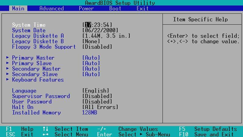
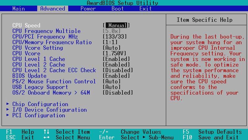
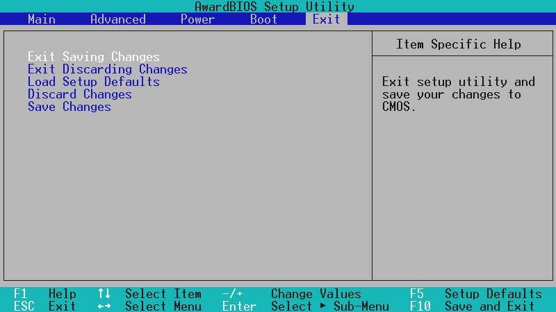
48 MAIN ADVANCED POWER BOOT EXIT <F1> or <Alt + H> <Esc> or<alt + X> or (keypad arrow) or (keypad arrows) - (minus key) + (plus key) or spacebar <Enter> <Home> or <PgUp> <End> or <PgDn> <F5> <F10> 48
49 49
50 50
51 51
52 52
53 53
54 54
55 CR2032 3V Lithium Cell CMOS Power A7A266-E CLRTC Short solder points to Clear CMOS A7A266-E Clear RTC RAM 55
56 56
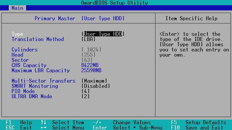
57 CPU CPU [Auto] CPU CPU [manual] 57

58 58
59 59
60 60
61 61
62 62
63 63
64 64
65 65
66 66
67 67
68 68
69 69
70 70
71 71
72 72
73 73
74 74

75 75
76 76
77 77
78 78


79 79


80 80
81 81
82 82
83 83
84 84


85 85


86 86

87 Line Out Line In Mic 87

88 88


89 89
90 90
CUV4X-E. JumperFree TM PC-133/VC MHz FSB AGP PRO/4X Socket 370
 CUV4X-E JumperFree TM PC-133/VC133 133MHz FSB AGP PRO/4X Socket 370 2 2000 3 4 5 6 7 8 9 10 11 12 1 2 3 4 567 8 24 23 22 21 20 19 18 17 16 15 14 13 12 11 10 9 13 20.9cm (8.22in) PS/2 VIO USB COM1 LED Socket
2 2001
 CUV266 Socket 370 2 2001 3 4 5 6 7 8 9 10 11 12 1 2 3 4 5 6 27 26 25 24 23 22 21 20 19 18 17 1615 14 13 1211109 8 7 13 24.5cm (9.64in) PS/2 USB1_PWR CUV266 USB RJ-45 COM1 JTPWR 0 1 01 3 4 01 01 5 6 VIO3
CUV4X. JumperFree TM PC-133 AGP/4X
 CUV4X JumperFree TM PC-133 AGP/4X 2 2000 3 4 5 6 7 8 9 10 11 12 1 2 3 4 5 6 7 25 24 23 22 21 20 19 18 17 16 15 14 13 12 11 10 9 8 13 20.9cm (8.22in) PS/2 VIO CPU_FAN Socket 370 cyrix 133 VIA VT82C694X
A7PRO. Jumper TM PC133/VC MHz FSB AGP Pro/4X
 A7PRO Jumper TM PC133/VC133 200MHz FSB AGP Pro/4X 2000 2 3 4 5 6 7 8 9 10 11 / 12 1 2 3 4 5 6 7 8 25 24 23 22 21 20 19 18 17 16 15 14 13 12 11 10 9 13 24.5cm (9.64in) PS/2 JTPWR PWR_FAN VIO USB COM1 Socket
JumperFree TM CUA
 JumperFree TM CUA 2 2000 3 4 5 6 7 8 9 10 11 3D Graphics 12 1 2 3 4 5 6 7 8 27 26 25 24 23 22 21 20 19 18 17 16 15 14 13 12 11 109 13 21.3 cm (8.38 in) PS/2KBMS VIO USB 2MB SDRAM IC_ PWR_ FAN COM2 2MB
P4T533-C
 P4T533-C T1047 2002 ii iii iv v vi vii viii 1 2 2 3 Jumper Mode Jumper Free (Default) ix x xi xii 1 2 3 4 1 23 4 5 6 7 32 31 30 29 28 27 26 25 24 23 8 9 10 11 12 13 14 22 21 20 19 18 17 16 15 33 34 35
P4G8X P4G8X Deluxe P4G8X
 P4G8X P4G8X Deluxe P4G8X Motherboard T1133 2002 2 3 4 5 6 7 8 1 2 2 3 Jumper Mode Jumper Free (Default) 9 10 11 12 1-1 1-2 1-3 1-4 1-5 1-6 1 2 3 4 5 6 7 8 21 20 19 9 10 18 17 16 1514 13 12 11 22 23 24
P4B533-E. Motherboard
 P4B533-E Motherboard T986 2002 2 3 4 5 6 7 8 1 2 2 3 Jumper Mode Jumper Free (Default) 9 10 11 12 1-1 1-2 1-3 1-4 1-5 1-6 1 2 3 4 5 6 7 23 22 8 9 10 21 20 11 12 19 13 18 17 16 15 14 24 25 26 27 28 29
K1140A. December Checklist. Copyright 2002 ASUSTeK COMPUTER INC. All Rights Reserved.
 P4PE Motherboard Checklist K1140A December 2002 Copyright 2002 ASUSTeK COMPUTER INC. All Rights Reserved. ii Contents Features iii Safeguards Contents iv Contents v vi vii viii ix x P4PE xi xii P4PE Chapter
A7V8X-MX. Motherboard
 A7V8X-MX Motherboard T1397 2003 ii iii iv v vi A7V8X-MX-TAYZ 10839 11036 6 0 12XX56XX90 vii viii ix x 1-1 1-2 TM 1 2 3 4 5 6 7 8 14 13 9 10 12 11 15 16 17 18 19 20 25 24 23 22 21 1-3 1-4 1-5 24.5cm (9.6in)
P4B533-X. Motherboard
 P4B533-X Motherboard C1458 2003 2 3 4 5 6 7 1 2 2 3 Jumper Mode Jumper Free (Default) 8 9 10 1-1 1-2 1-3 1-4 SB_PWR1 P4B533-X P4B533-X Onboard LED ON Standby Power OFF Powered Off 1-5 CPU_FAN1 ATX12V1
P4S800D-X. Motherboard
 P4S800D-X Motherboard T1753 2004 2 3 4 5 P4S800D-X-TAYZ 6 10839 11036 0 11XX11XX11 6 7 8 1-1 1-2 1-3 SB_PWR1 P4S800D-X P4S800D-X Onboard LED ON Standby Power OFF Powered Off 1-4 R 24.5cm (9.6in) PWR_FAN1
P4V800-X. Motherboard
 P4V800-X Motherboard C1371 2003 2 3 4 5 6 TM 1 2 2 3 Jumper Mode Jumper Free (Default) 7 8 9 10 1-1 1-2 1-3 1 2 3 4 5 6 16 8 7 15 14 13 9 10 12 17 11 18 19 20 21 22 27 26 25 24 23 1-4 1-5 1-6 1-7 19.3cm
P4PE2-X. Motherboard
 P4PE2-X Motherboard C1788 2004 2 3 4 5 6 7 1 2 2 3 Jumper Mode Jumper Free (Default) 8 9 10 1-1 1-2 1-3 SB_PWR P4PE2-X P4PE2-X Onboard LED ON Standby Power OFF Powered Off 1-4 CPU_FAN ATX12V SPDIF_O COM1
P4P800-X. Motherboard
 P4P800-X Motherboard 2 C1718 3 4 5 6 1 2 2 3 Jumper Mode Jumper Free (Default) 7 8 9 10 1-1 1-2 1-3 SB_PWR P4P800-X P4P800-X Onboard LED ON Standby Power OFF Powered Off 1-4 20.8cm (8.2in) CPU_FAN ATX12V
2. FEATURES. 2.1 The CUV-NT
 Specifications 2. FEA TURES 2. FEATURES 2.1 The The motherboard is carefully designed for the demanding PC user who wants advanced features processed by the fastest processors. 2.1.1 Specifications Latest
1. FEATURES. 1.1 The A7V-VM Motherboard
 1. FEATURES 1.1 The Motherboard The motherboard is carefully designed for the demanding PC user who wants high-performance features in a small package. 1.1.1 Specifications AMD Athlon /Duron Processor
CLK. Slot1 VIA ATX Mainboard. User s Manual 4
 2.1. Mainboard Layout Drawing CLK AGP 1 H14.318 Slot1 VIA693-133 ATX Mainboard ISA2 ISA1 User s Manual 4 2.2. Hardware Installation Steps 2.2.1. Installing System Memory The mainboard is equipped with
1. FEATURES. 1.1 The CUW-AM
 Specifications 1. FEA TURES 1. FEATURES 1.1 The The motherboard is carefully designed for the demanding PC user who wants advanced features processed by the fastest processors. 1.1.1 Specifications Latest
A7A266. DDR SDRAM 266MHz FSB AGP Pro/4X Socket A Motherboard USER S MANUAL
 A7A266 DDR SDRAM 266MHz FSB AGP Pro/4X Socket A Motherboard USER S MANUAL USER'S NOTICE No part of this manual, including the products and software described in it, may be reproduced, transmitted, transcribed,
6SMM7 USER'S MANUAL. Celeron TM Socket 370 Processor MAINBOARD REV. 1.1 First Edition R
 USER'S MANUAL. System power on by Keyboard: If your ATX power supply supports larger than 00 ma 5V Stand-By current (dependent on the specification of keyboards), you can power on your system by entering
K8N-E Deluxe. Motherboard
 K8N-E Deluxe Motherboard C1581 2004 ii iii iv v vi vii viii ix 1 2 2 3 Jumper Mode Jumper Free (Default) x xi xii 1-1 1-2 1-3 1-4 1-5 1-6 SB_PWR K8V-E K8N-E Onboard LED ON Standby Power OFF Powered
6BMM USER'S MANUAL. 3. Support Modem Ring-On. (Include internal Modem and external modem on COM A and COM B)
") USER'S MANUAL. System power on by PS/2 Mouse: First, enable this function in CMOS Setup, then you can power on the system by double clicking the right or left button of your PS/2 Mouse. 2. System power
USER'S MANUAL. System power on by PS/2 Mouse: First, enable this function in CMOS Setup, then you can power on the system by double clicking the right or left button of your PS/2 Mouse. 2. System power
MEL Socket 370 Motherboard USER S MANUAL
 R MEL Socket 370 Motherboard USER S MANUAL USER'S NOTICE No part of this manual, including the products and software described in it, may be reproduced, transmitted, transcribed, stored in a retrieval
6BA USER'S MANUAL. For Intel Pentium II / III / Celeron Processor MAINBOARD REV. 3.0 First Edition R
 USER'S MANUAL. System power on by PS/2 Mouse: First, enable this function in CMOS Setup, then you can power on the system by double clicking the right or left button of your PS/2 Mouse. 2. System power
686BX USER'S MANUAL. 3. Supports 3 steps ACPI LED. 4. Modem Ring-On. (COM B) 5. Wake-Up on LAN. (on J13) 6. Supports LDCM
 5. Wake-Up on LAN. (on J13) 6. Supports LDCM") 686BX USER'S MANUAL. System power on by PS/2 Mouse: First, enable this function in CMOS Setup, then you can power on the system by double clicking the right or left button of your PS/2 Mouse. 2. System
686BX USER'S MANUAL. System power on by PS/2 Mouse: First, enable this function in CMOS Setup, then you can power on the system by double clicking the right or left button of your PS/2 Mouse. 2. System
Chapter 1 Specification
 SL-I / I-L Chapter Specifications COM LPT Chapter Specification - Mainboard Layout and Components Setup CPU Fan Analog Monitor Front Audio CD-ROM Audio LAN Controller (for I-L) ne in CD AC'97 IT872F JKB
TABLE OF CONTENTS 1. INTRODUCTION 2. SPECIFICATION 3. HARDWARE INSTALLATION. Table of Contents 1.1. PREFACE KEY FEATHERS...
 Table of Contents TABLE OF CONTENTS 1. INTRODUCTION 1.1. PREFACE... 1-1 1.2. KEY FEATHERS... 1-1 1.3. PERFORMANCE LIST... 1-2 1.4. BLOCK DIAGRAM... 1-3 1.5. INTRODUCE THE PENTIUM II/ III PROCESSORS...
C ii
 K8S-MX Motherboard C1647 2004 ii iii iv v vi vii 1 2 2 3 Jumper Mode Jumper Free (Default) viii ix x 1-1 1-2 1-3 1-4 SB_PWR K8S-MX K8S-MX Onboard LED ON Standby Power OFF Powered Off 1-5 R 19.3cm (7.6in)
TABLE OF CONTENTS 1. INTRODUCTION 2. SPECIFICATION 3. HARDWARE INSTALLATION 6BA
 6BA TABLE OF CONTENTS 1. INTRODUCTION 1.1. PREFACE...1-1 1.2. KEY FEATURES...1-1 1.3. PERFORMANCE LIST...1-2 1.4. BLOCK DIAGRAM...1-3 1.5. INTRODUCE THE Pentium II / III Processor...1-4 1.6. What is AGP?...1-5
Pentium. P2B-F II Motherboard USER S MANUAL
 Pentium R P2B-F II Motherboard USER S MANUAL Product Name: ASUS P2B-F Manual Revision: 1.00 E277 Release Date: October1998 USER'S NOTICE No part of this manual, including the products and software described
TABLE OF CONTENTS 1. INTRODUCTION 2. SPECIFICATION 3. HARDWARE INSTALLATION 6BMM 1.1. PREFACE KEY FEATURES...1-1
 6BMM TABLE OF CONTENTS 1. INTRODUCTION 1.1. PREFACE...1-1 1.2. KEY FEATURES...1-1 1.3. PERFORMANCE LIST...1-2 1.4. BLOCK DIAGRAM...1-3 1.5. INTRODUCE THE Pentium II Processor & AGP...1-4 1.6. What is AGP?...1-6
X533. User Manual. Version 1.0 Published April 2003 Copyright 2003 ASRock INC. All rights reserved.
 X533 User Manual Version 1.0 Published April 2003 Copyright 2003 ASRock INC. All rights reserved. 1 Copyright Notice: No part of this manual may be reproduced, transcribed, transmitted, or translated in
A7N266. JumperFree DDR DRAM 266MHz FSB NVIDIA nforce 420 Chipset Socket A Motherboard USER S MANUAL
 A7N266 JumperFree DDR DRAM 266MHz FSB NVIDIA nforce 420 Chipset Socket A Motherboard USER S MANUAL USER'S NOTICE No part of this manual, including the products and software described in it, may be reproduced,
Chapter 2 HARDWARE INSTALLATION. 2.1 Central Processing Unit: CPU CHAPTER 2
 Chapter 2 HARDWARE INST 2.1 Central Processing Unit: CPU The mainboard operates with Intel Pentium II/Celeron TM processor. The mainboard uses a CPU Slot called Slot 1 for easy CPU installation and a jumper
TUSL2-M Intel 815E Chipset microatx Motherboard USER S MANUAL
 TUSL2-M Intel 815E Chipset microatx Motherboard USER S MANUAL USER'S NOTICE No part of this manual, including the products and software described herein, may be reproduced, transmitted, transcribed, stored
M266A. User Manual. Version 1.0 Published April 2003 Copyright 2003 ASRock INC. All rights reserved.
 M266A User Manual Version 1.0 Published April 2003 Copyright 2003 ASRock INC. All rights reserved. 1 Copyright Notice: No part of this manual may be reproduced, transcribed, transmitted, or translated
CUSL-L. Intel 815 microatx Motherboard USER S MANUAL
 Intel 815 microatx Motherboard USER S MANUAL USER'S NOTICE No part of this manual, including the products and software described in it, may be reproduced, transmitted, transcribed, stored in a retrieval
P5RD1-VM. Motherboard
 P5RD1-VM Motherboard T2440 2006 2 3 4 5 6 7 1 2 2 3 Jumper Mode Jumper Free (Default) P5RD1VM-TAYZ 10839 11036 6 0 11XX11XX11 8 9 10 1-1 1-2 1-3 1-4 P5RD1-VM LED1 P5RD1-VM Onboard LED ON Standby Power
P2V Pentium II/Celeron Motherboard USER S MANUAL
 P2V Pentium II/Celeron Motherboard USER S MANUAL Product Name: ASUS P2V Manual Revision: 1.01 E384 Release Date: May 1999 USER'S NOTICE No part of this manual, including the products and software described
TABLE OF CONTENTS 1. INTRODUCTION 2. SPECIFICATION 3. HARDWARE INSTALLATION 6EX 1.1. PREFACE KEY FEATURES PERFORMANCE LIST...
 6EX TABLE OF CONTENTS 1. INTRODUCTION 1.1. PREFACE...1-1 1.2. KEY FEATURES...1-1 1.3. PERFORMANCE LIST...1-2 1.4. BLOCK DIAGRAM...1-3 1.5. INTRODUCE THE Pentium II Processor & AGP...1-4 1.6 What is AGP?...
Motherboard Specifications, A8AE-LE (AmberineM)
") 1 of 7 6/28/2009 11:14 PM» Return to original page Motherboard Specifications, A8AE-LE (AmberineM) Motherboard specifications table Motherboard layout and photos Clearing the CMOS settings Clearing the
1 of 7 6/28/2009 11:14 PM» Return to original page Motherboard Specifications, A8AE-LE (AmberineM) Motherboard specifications table Motherboard layout and photos Clearing the CMOS settings Clearing the
TABLE OF CONTENTS 1. INTRODUCTION 2. SPECIFICATION 3. HARDWARE INSTALLATION 6EM 1.1. PREFACE KEY FEATURES PERFORMANCE LIST...
 6EM TABLE OF CONTENTS 1. INTRODUCTION 1.1. PREFACE...1-1 1.2. KEY FEATURES...1-1 1.3. PERFORMANCE LIST...1-2 1.4. BLOCK DIAGRAM...1-3 1.5. INTRODUCE THE Pentium II Processor & AGP...1-4 1.6 What is AGP?...1-6
P5VD1-X. Motherboard
 P5VD1-X Motherboard T2180 2005 2 3 4 5 6 7 1 2 2 3 Jumper Mode Jumper Free (Default) 8 P5GD1-TAYZ 10839 11036 6 0 11XX11XX11 9 10 11 12 1-1 1-2 1-3 1-4 SB_PWR P5VD1-X P5VD1-X Onboard LED ON Standby
TABLE OF CONTENTS 1. INTRODUCTION 2. SPECIFICATION 3. HARDWARE INSTALLATION 6BXDS 1.1. PREFACE KEY FEATURES...1-1
 6BXDS 1. INTRODUCTION TABLE OF CONTENTS 1.1. PREFACE...1-1 1.2. KEY FEATURES...1-1 1.3. PERFORMANCE LIST...1-2 1.4. BLOCK DIAGRAM...1-3 1.5. INTRODUCE THE Pentium II Processor...1-4 1.6. What is AGP?...1-6
A7M266. DDR SDRAM 266MHz FSB AGP Pro/4X Socket A Motherboard USER S MANUAL
 A7M266 DDR SDRAM 266MHz FSB AGP Pro/4X Socket A Motherboard USER S MANUAL USER'S NOTICE No part of this manual, including the products and software described in it, may be reproduced, transmitted, transcribed,
Quick Start Guide. SY-6BB V1.0 Mainboard F C. Introduction. Installation. Hardware. Quick BIOS Setup. The SOYO CD
 SY-6BB V.0 Mainboard Quick Start Guide Introduction Hardware Installation Quick BIOS Setup The SOYO CD F C Tested To Comply With FCC Standards FOR HOME OR OFFICE USE POST CONSUMER 00% RECYCLED PAPER SOYO
PE Pro-HT. User Manual. Version 1.0 Published January 2003 Copyright 2003 ASRock INC. All rights reserved.
 PE Pro-HT User Manual Version 1.0 Published January 2003 Copyright 2003 ASRock INC. All rights reserved. 1 Copyright Notice: No part of this manual may be reproduced, transcribed, transmitted, or translated
TABLE OF CONTENTS 1. INTRODUCTION 2. SPECIFICATION 3. HARDWARE INSTALLATION. Table Of Contents 1.1. PREFACE KEY FEATURES...
 Table Of Contents TABLE OF CONTENTS 1. INTRODUCTION 1.1. PREFACE...1-1 1.2. KEY FEATURES...1-1 1.3. PERFORMANCE LIST...1-2 1.4. BLOCK DIAGRAM...1-3 1.5. INTRODUCE THE Pentium II Processor & AGP...1-4 1.6.
P4S133. User Guide. Motherboard
 P4S133 User Guide Motherboard Checklist P4S133 E1025 April 2002 Copyright 2002 ASUSTeK COMPUTER INC. All Rights Reserved. No part of this manual, including the products and software described in it, may
Mainboard User s Manual
 This publication, including all photographs, illustrations and software, is protected under international copyright laws, with all rights reserved. Neither this manual, nor any of the material contained
K7VM2. User Manual. Version 3.1 Published July 2003 Copyright 2003 ASRock INC. All rights reserved.
 K7VM2 User Manual Version 3. Published July 2003 Copyright 2003 ASRock INC. All rights reserved. Copyright Notice: No part of this manual may be reproduced, transcribed, transmitted, or translated in any
P4P800 Deluxe. Motherboard
 P4P800 Deluxe Motherboard T1323 2003 2 3 4 5 6 7 8 1 2 2 3 Jumper Mode Jumper Free (Default) 9 10 11 12 1-1 1-2 1-3 1-4 1-5 1-6 1-7 1 2 3 4 5 6 7 8 9 21 10 20 19 18 17 16 15 14 13 12 11 22 23 24 25 26
CUW-RM Intel 810 microatx Motherboard USER S MANUAL
 CUW-RM Intel 810 microatx Motherboard USER S MANUAL USER'S NOTICE No part of this manual, including the products and software described in it, may be reproduced, transmitted, transcribed, stored in a retrieval
P4SE. User Guide. Motherboard
 P4SE User Guide Motherboard Checklist E1141 Second Edition October 2002 Copyright 2002 ASUSTeK COMPUTER INC. All Rights Reserved. No part of this manual, including the products and software described in
TABLE OF CONTENTS 1. INTRODUCTION 2. SPECIFICATION 3. HARDWARE INSTALLATION 6LX7 / 6LX7A 1.1. PREFACE KEY FEATHERS...
 TABLE OF CONTENTS 1. INTRODUCTION 1.1. PREFACE...1-1 1.2. KEY FEATHERS...1-1 1.3. PERFORMANCE LIST...1-3 1.4. BLOCK DIAGRAM...1-4 1.5. INTRODUCE THE INTEL Celeron TM Socket 370 Processor...1-5 1.6. WHAT
FAN3 Connector AUX-IN Connector. CD-IN Connector FAN2 Connector. Intel /100 LAN Controller CPU2 FAN Connector AGP Pro Slot USB Connector
 PS/2 Mouse Connector SPP/EPP/ECP Parallel Port RJ45 0/00 LAN Jack (Optional) Speaker Out FAN3 Connector AUX-IN Connector PS/2 Keyboard Connector USB Port Port 2 Port Line-In MIC-In CD-IN Connector FAN2
M2N68-LA (Narra 3) Motherboard
 Motherboard") (Narra 3) Motherboard E3503 First Edition V1 October 2007 Contents (Narra 3) specifications summary... iii 1. Motherboard layout... 1 2. Central Processing Unit (CPU)... 2 2.1 Overview... 2 2.2 Installing
(Narra 3) Motherboard E3503 First Edition V1 October 2007 Contents (Narra 3) specifications summary... iii 1. Motherboard layout... 1 2. Central Processing Unit (CPU)... 2 2.1 Overview... 2 2.2 Installing
K7VT4A+ User Manual. Version 1.0 Published May 2004 Copyright 2004 ASRock INC. All rights reserved.
 K7VT4A+ User Manual Version.0 Published May 2004 Copyright 2004 ASRock INC. All rights reserved. Copyright Notice: No part of this manual may be reproduced, transcribed, transmitted, or translated in any
TABLE OF CONTENTS 1. INTRODUCTION 2. SPECIFICATION 3. HARDWARE INSTALLATION 6VX PREFACE KEY FEATHERS
 6VX7 TABLE OF CONTENTS 1. INTRODUCTION 1.1. PREFACE... 1-1 1.2. KEY FEATHERS... 1-1 1.3. PERFORMANCE LIST... 1-2 1.4. BLOCK DIAGRAM... 1-3 1.5. INTRODUCE THE INTEL Celeron TM Socket 370 Processor... 1-4
TUWE-M Intel 810E2 MicroATX Motherboard USER S MANUAL
 TUWE-M Intel 810E2 MicroATX Motherboard USER S MANUAL USER'S NOTICE No part of this manual, including the products and software described in it, may be reproduced, transmitted, transcribed, stored in a
K7V Slot A Motherboard USER S MANUAL
 R K7V Slot A Motherboard USER S MANUAL USER'S NOTICE No part of this manual, including the products and software described in it, may be reproduced, transmitted, transcribed, stored in a retrieval system,
Important Information
 Important Information Copyright This publication, including all photographs, illustrations and software, is protected under international copyright laws, with all rights reserved. Neither this manual,
Pentium. P2B-B II/Celeron TM Motherboard USER S MANUAL
 Pentium R P2B-B II/Celeron TM Motherboard USER S MANUAL Product Name: ASUS P2B-B Manual Revision: 1.02 E309 Release Date: December1998 USER'S NOTICE No part of this manual, including the products and software
A7N8X-X. User Guide. Motherboard
 A7N8X-X User Guide Motherboard Checklist E1294 First Edition April 2003 Copyright 2003 ASUSTeK COMPUTER INC. All Rights Reserved. No part of this manual, including the products and software described in
P2B-D / P2B-DS USER S MANUAL
 R P2B-D / P2B-DS Dual Pentium II Motherboards USER S MANUAL Special Features P2B-DS Adaptec 7890 SCSI Chipset Adaptec 3860 SCSI Transceiver USER'S NOTICE No part of this manual, including the products
Chapter 1. Getting Started Getting Started
 Getting Started Chapter 1. Getting Started Getting Started 1 Thank you for purchasing the MS-6579 (v1.x) M-ATX mainboard. The MS-6579 mainboard is based on Intel Brookdale-E GMCH & ICH4 chipsets for optimal
Pentium. SP98AGP-X ATX Motherboard USER S MANUAL
 Pentium R SP98AGP-X ATX Motherboard USER S MANUAL USER S NOTICE No part of this manual, including the products and software described in it, may be reproduced, transmitted, transcribed, stored in a retrieval
ME-99B Socket 370 Baby AT Motherboard USER S MANUAL
 R ME-99B Socket 370 Baby AT Motherboard USER S MANUAL Product Name: ASUS ME-99B Manual Revision: 1.01 E403 Release Date: June 1999 USER'S NOTICE No part of this manual, including the products and software
Pentium. P2L97 II Motherboard USER S MANUAL
 Pentium R P2L97 II Motherboard USER S MANUAL Product Name: ASUS P2L97 Manual Revision: 2.05 E266 Release Date: October 1998 USER'S NOTICE No part of this manual, including the products and software described
TABLE OF CONTENTS 1. INTRODUCTION 2. SPECIFICATION 3. HARDWARE INSTALLATION. Table of Contents 1.1. PREFACE KEY FEATURES...
 Table of Contents TABLE OF CONTENTS 1. INTRODUCTION 1.1. PREFACE...1-1 1.2. KEY FEATURES...1-1 1.3. PERFORMANCE LIST...1-2 1.4. BLOCK DIAGRAM...1-3 1.5. INTRODUCE THE INTEL Celeron TM Socket 370 Processor...1-4
MAINBOARD. Installation Guide
 MAINBOARD Rev: 1.01H Date: May - 99 All other product names are trademarks or copyrights of their respective owners. Specifications and information contained in this manual are subject to change without
TABLE OF CONTENTS 1. INTRODUCTION 1.1. PREFACE KEY FEATURES PERFORMANCE LIST BLOCK DIAGRAM...
 TABLE OF CONTENTS 1. INTRODUCTION 1.1. PREFACE... 1-1 1.2. KEY FEATURES... 1-1 1.3. PERFORMANCE LIST... 1-3 1.4. BLOCK DIAGRAM... 1-4 1.5. INTRODUCE THE PCI - BUS... 1-5 1.6. FEATURES... 1-5 2. SPECIFICATION
TABLE OF CONTENTS 1. INTRODUCTION 2. SPECIFICATION 3. HARDWARE INSTALLATION. Table of Contents 1.1. PREFACE KEY FEATURES...
 Table of Contents 1. INTRODUCTION TABLE OF CONTENTS 1.1. PREFACE...1-1 1.2. KEY FEATURES...1-1 1.3. PERFORMANCE LIST...1-2 1.4. BLOCK DIAGRAM...1-3 1.5. INTRODUCE THE Pentium II Processor...1-4 1.6. What
P3C2000 JumperFree ATX Motherboard USER S MANUAL
 R P3C2000 JumperFree ATX Motherboard USER S MANUAL USER'S NOTICE No part of this manual, including the products and software described in it, may be reproduced, transmitted, transcribed, stored in a retrieval
5AMMC USER'S MANUAL. Support Intel Pentium, MMX, Cyrix/IBM 6x86MX, MII, AMD K5, K6, K6-2 & IDT C6 CPUs. Support auto detect CPU Voltage.
 5AMMC USER'S MANUAL Support Intel Pentium, MMX, Cyrix/IBM 6x86MX, MII, AMD K5, K6, K6-2 & IDT C6 s. Support auto detect Voltage. Support Parity check or Ecc Function. Support Fully.0 Specification. Support
P2-99B Pentium III / II / Celeron TM Motherboard USER S MANUAL
 R P2-99B Pentium III / II / Celeron TM Motherboard USER S MANUAL Product Name: ASUS P2-99B Manual Revision: 1.01 E388 Release Date: May 1999 USER'S NOTICE No part of this manual, including the products
CUW(E)-FX Intel 810 FlexATX Motherboard USER S MANUAL
-FX Intel 810 FlexATX Motherboard USER S MANUAL") CUW(E)-FX Intel 810 FlexATX Motherboard USER S MANUAL Special Features CUWE-FX Intel 810E Chipset with support for 133/100/66MHz FSB 4MB 32-bit 133MHz SDRAM display cache onboard CUW-FX Intel 810 Chipset
CUW(E)-FX Intel 810 FlexATX Motherboard USER S MANUAL Special Features CUWE-FX Intel 810E Chipset with support for 133/100/66MHz FSB 4MB 32-bit 133MHz SDRAM display cache onboard CUW-FX Intel 810 Chipset
GA - 686LX USER'S MANUAL. Pentium II Processor MAINBOARD. REV. 1 First Edition
 GA - 686LX USER'S MANUAL Pentium II Processor MAINBOARD REV. 1 First Edition GA-686LX The author assumes no responsibility for any errors or omissions which may appear in this document nor does it make
User s Manual Full-Size PICMG 1.3 SHB Version 1.0
 3308360 User s Manual Full-Size PICMG 1.3 SHB Version 1.0 Copyrights This document is copyrighted and all rights are reserved. It does not allow any non authorization in copied, photocopied, translated
(1) 2. : Terminator P4 533 : 1.01 T1125 :
 2. : Terminator P4 533 : 1.01 T1125 :") Terminator P4 533 (1) 2 2002 : Terminator P4 533 : 1.01 T1125 : 2002 9 2 0800-093456 3 0800-093456 3 02 2506-2558 0800-089558 AS TERMINATOR B B. TF2 17PG010353 17PG010353 3 ... 2... 3... 4... 7 :... 9...
Terminator P4 533 (1) 2 2002 : Terminator P4 533 : 1.01 T1125 : 2002 9 2 0800-093456 3 0800-093456 3 02 2506-2558 0800-089558 AS TERMINATOR B B. TF2 17PG010353 17PG010353 3 ... 2... 3... 4... 7 :... 9...
IP402 COM Express TYPE6 Baseboard USER S MANUAL Version 1.0A
 IP402 COM Express TYPE6 Baseboard USER S MANUAL Version 1.0A Acknowledgments All product names or trademarks are properties of their respective owners. ii IP402 User s Manual Table of Contents Introduction...
TABLE OF CONTENTS 1. INTRODUCTION 2. SPECIFICATION 3. HARDWARE INSTALLATION 6VMA 1.1. PREFACE KEY FEATURES...1-1
 6VMA TABLE OF CONTENTS 1. INTRODUCTION 1.1. PREFACE...1-1 1.2. KEY FEATURES...1-1 1.3. PERFORMANCE LIST...1-2 1.4. BLOCK DIAGRAM...1-3 1.5. INTRODUCE THE Pentium II / III Processor...1-4 1.6. What is AGP?...1-5
Electronic Emission Notices
 Electronic Emission Notices Federal Communications Commission (FCC) Statement This equipment has been tested and found to comply with the limits for a Class B digital device, pursuant to Part 5 of FCC
6VXE USER'S MANUAL. 3. Supports 3 steps ACPI LED. 4. Modem Ring-On. (COM A, B).
.") USER'S MANUAL. System power on by PS/2 Mouse: First, enable this function in CMOS Setup, then you can power on the system by double clicking the right or left button of your PS/2 Mouse. 2. System power
USER'S MANUAL. System power on by PS/2 Mouse: First, enable this function in CMOS Setup, then you can power on the system by double clicking the right or left button of your PS/2 Mouse. 2. System power
MAINBOARD PV42. Installation Guide
 MAINBOARD PV42 Rev: 1.00H Date: July - 99 All other product names are trademarks or copyrights of their respective owners. Specifications and information contained in this manual are subject to change
Quick Start USER S MANUAL
 E912 P4B266-LA Intel 845 Micro-ATX Motherboard Quick Start USER S MANUAL No part of this manual, including the products and software described in it, may be reproduced, transmitted, transcribed, stored
6BXC USER'S MANUAL. 3. Supports 3 steps ACPI LED. 4. Modem Ring-On. (COM A, B).
.") USER'S MANUAL. System power on by PS/2 Mouse: First, enable this function in CMOS Setup, then you can power on the system by double clicking the right or left button of your PS/2 Mouse. 2. System power
USER'S MANUAL. System power on by PS/2 Mouse: First, enable this function in CMOS Setup, then you can power on the system by double clicking the right or left button of your PS/2 Mouse. 2. System power
TABLE OF CONTENTS 1. INTRODUCTION 2. SPECIFICATION 3. HARDWARE INSTALLATION. Table of Contents 1.1. PREFACE KEY FEATURES...
 Table of Contents TABLE OF CONTENTS 1. INTRODUCTION 1.1. PREFACE...1-1 1.2. KEY FEATURES...1-1 1.3. PERFORMANCE LIST...1-2 1.4. BLOCK DIAGRAM...1-3 1.5. INTRODUCE THE Pentium II/III Processor...1-4 1.6.
A7V USER S MANUAL. Socket A Motherboard. JumperFree PC133/VC MHz FSB AGP Pro/4X
 A7V JumperFree PC133/VC133 200MHz FSB AGP Pro/4X Socket A Motherboard USER S MANUAL USER'S NOTICE No part of this manual, including the products and software described in it, may be reproduced, transmitted,
P4S800D. Motherboard
 P4S800D Motherboard T1443 2003 2 3 4 5 6 7 1 2 2 3 Jumper Mode Jumper Free (Default) P4S800D-TAYZ 6 10839 11036 0 11XX11XX11 8 9 10 1-1 1-2 1-3 1-4 SB_PWR1 P4S800D P4S800D Onboard LED ON Standby Power
P4S133-VM. User Guide. Motherboard
 P4S133-VM User Guide Motherboard Checklist P4S133-VM E983 March 2002 Copyright 2002 ASUSTeK COMPUTER INC. All Rights Reserved. No part of this manual, including the products and software described in it,
Getting Started. Chapter 1. Introduction. Chapter 1. Getting Started
 Introduction Chapter. Introduction Chapter. Getting Started Getting Started Thank you for purchasing the MS-6367 v.x M-ATX mainboard. The MS-6367 mainboard is a superior computer mainboard based on nvidia
Important Information
 Important Information Copyright This publication, including all photographs, illustrations and software, is protected under international copyright laws, with all rights reserved. Neither this manual,
Assignment 5. You can configure hardware options by setting jumper on the mainboard. See Figure 2-1 for jumper locations. Set a jumper as follows:
 CIS 170 Microcomputer Hardware Name: Assignment 5 From the lack of having enough peripherals for this course (at least at this point), we have the necessity of doing some experiments mentally rather than
Introduction CHAPTER 1
 CHAPTER 1 Introduction The ROBO-667 all-in-one single board computer is designed to fit a high performance Pentium-III based CPU and compatible for high-end computer system with PCI/ISA Bus architecture.
Introduction CHAPTER 1
 CHAPTER 1 Introduction The ACTI-788 all-in-one single board computer is designed to fit a high performance Celeron based CPU and compatible for high-end computer system application with PCI/ISA bus architecture.
Microsoft, MS-DOS and Windows are registered trademarks of Microsoft
 Preface Copyright This publication, including all photographs, illustrations and software, is protected under international copyright laws, with all rights reserved. Neither this manual, nor any of the
MAINBOARD. Installation Guide
 MAINBOARD Rev: 1.01H Date: April - 99 All other product names are trademarks or copyrights of their respective owners. Specifications and information contained in this manual are subject to change without
P2V-B Pentium III / II / Celeron TM Motherboard USER S MANUAL
 R P2V-B Pentium III / II / Celeron TM Motherboard USER S MANUAL Product Name: ASUS P2V-B Manual Revision: 1.02 E353 Release Date: March 1999 USER'S NOTICE No part of this manual, including the products