P4B533-E. Motherboard
|
|
|
- Lillian Shepherd
- 5 years ago
- Views:
Transcription


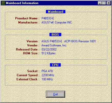
1 P4B533-E Motherboard
2 T
3 3
4 4
5 5
6 6
7 7
8 8
9 Jumper Mode Jumper Free (Default) 9
10 10
11 11
12 12


13
14


15 1-1
16 1-2


17 1-3


18 1-4
19 1-5
20 1-6

21
22 1-8
23 1-9
24 1-10
25 1-11
26 1-12
27
28


29 2-1
30 24.5cm (9.6in) CPU_FAN COM1 OVER_VOLT KBPWR USBPWR_34 Socket 478 PWR_FAN AGP_WARN TRPWR EZ_PLUG COM2 USBPWR_12 ATX12V FP_LO_SWR FP_LO_SWL FP_AUDIO LAN PHY DSW1 30.5cm (12.0in) FP_LINE_IN BCS1 BCS2 MODEM CD AUX PCISMB_SW1 PCISMB_SW2 CLRTC CHA_FAN USB_56 SPDIF P4B533-E USBPWR_56 GAME IEEE1394_2 IEEE1394_1 CHASSIS JEN SEC_RAID 1394_SW SB_PWR DSW2 Speech Controller RAID_SW SMARTCON AFPANEL SPEECH IR_CON SMB PRI_RAID IDE_LED PANEL 2-2
31 AGP_WARN ON Incorrect AGP Card OFF Correct AGP Card SB_PWR P4B533-E P4B533-E Onboard LED ON Standby Power OFF Powered Off 2-3


32 2-4


33

34 2-6


35 2-7

36 2-8


37 2-9


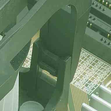
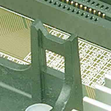
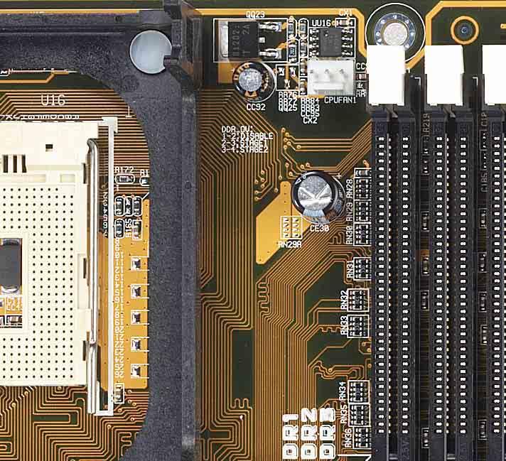
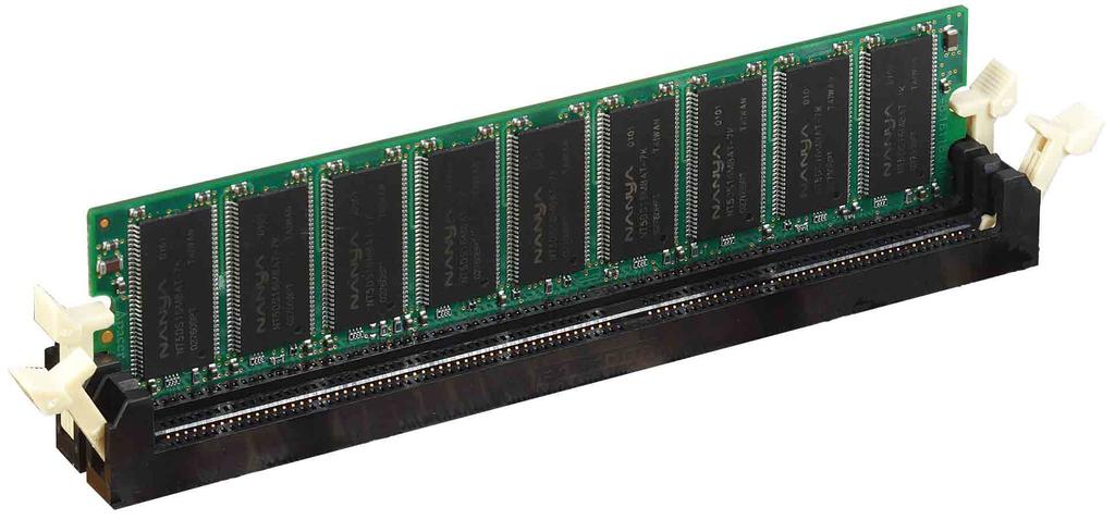
38 80 Pins P4B533-E 104 Pins P4B533-E 184-Pin DDR DIMM Sockets 2-10

39 2-11


40 2-12
41 2-13
42 2-14 A B C D E F G H


43 P4B533-E P4B533-E Accelerated Graphics Port (AGP PRO) 2-15
44 DSW ON 1.Frequency Selection 2.Frequency Selection 3.Frequency Selection 4.Frequency Selection 5.Frequency Selection 6.Frequency Selection ON OFF P4B533-E P4B533-E DIP Switches ON OFF DSW2 ON Frequency Multiple 2.Frequency Multiple 3.Frequency Multiple 4.Frequency Multiple JEN DSW1 ON DSW2 ON P4B533-E P4B533-E JumperFree Mode Setting Jumper Mode Jumper Free (Default) 2-16
45 DSW2 ON ON ON ON x 10.0x 11.0x 12.0x ON ON ON ON x x x x ON ON ON ON P4B533-E x x x x ON ON ON ON P4B533-E CPU Frequency Multiple Selection x x x x DSW ON ON ON ON CPU AGP PCI 100MHz 66MHz 33MHz 105MHz 70MHz 35MHz 109MHz 72MHz 36MHz 133MHz 66MHz 33MHz P4B533-E ON ON ON ON P4B533-E CPU External Frequency Selection CPU AGP PCI 141MHz 70MHz 35MHz 145MHz 72MHz 36MHz 166MHz 66MHz 33MHz 200MHz 66MHz 33MHz 2-17
46 2-18
47 KBPWR V (Default) VSB P4B533-E P4B533-E Keyboard Power Setting OVER_VOLT P4B533-E 2 1 Disable (Default) 3 2 Enable P4B533-E OVER_VOLT Setting 2-19
48 1 2 USBPWR_ V (Default) +5VSB USBPWR_ V (Default) +5VSB P4B533-E 1 2 USBPWR_ P4B533-E USB Device Wake Up +5V (Default) +5VSB 2-20
49 SPEECH P4B533-E P4B533-E Speaker Selector BUZZER LINEOUT (Default) PCISMB_SW1 PCISMB_SW2 P4B533-E P4B533-E PCISMB Setting Enable Disable (Default) 2-21
50 P4B533-E FP_LO_SWR FP_LO_SWL BLOR FLOR BLOL FLOL P4B533-E Internal Line Out Selector BCS1 BCS2 P4B533-E (CENTER/BASS) (BASS/CENTER) (Default) P4B533-E Bass Center Setting 2-22
51 RAID_SW P4B533-E P4B533-E PROMISE Setting Enable (Default) Disable 1394_SW P4B533-E Enable (Default) Disable P4B533-E 1394HEAD Setting 2-23
52 CR2032 3V Lithium Cell CMOS Power P4B533-E CLRTC Short solder points to Clear CMOS P4B533-E Clear RTC RAM 2-24
53 TIP: If the case-mounted LED does not light up, try reversing the 2-pin plug. P4B533-E IDE_LED P4B533-E HD Activity LED FLOPPY NOTE: Orient the red markings on the floppy ribbon cable to PIN 1. P4B533-E PIN 1 P4B533-E Floppy Disk Drive Connector 2-25
54 P4B533-E SEC_IDE PRI_IDE NOTE: Orient the red markings (usually zigzag) on the IDE ribbon cable to PIN 1. P4B533-E IDE Connectors PIN
55 NOTE: Orient the red markings (usually zigzag) on the IDE ribbon cable to PIN 1. SEC_RAID P4B533-E PIN 1 PRI_RAID P4B533-E RAID IDE Connectors 2-27
56 CHASSIS P4B533-E +5VSB_MB Chassis Signal GND P4B533-E Chassis Alarm Lead (Default) SMB P4B533-E 1 P4B533-E SMBus Connector FLOATING SMBCLK Ground SMBDATA +3V 2-28
57 ATXPWR EZ_PLUG P4B533-E +3.3VDC -12.0VDC GND PS_ON# GND GND GND -5.0VDC +5.0VDC +5.0VDC +3.3VDC +3.3VDC GND +5.0VDC GND +5.0VDC GND PWR_OK +5VSB +12.0VDC NC GND GND +12V ATX12V +12V DC GND P4B533-E ATX & Auxiliary Power Connectors +12V DC GND 2-29
58 CPU_FAN GND +12V Rotation PWR_FAN Rotation +12V GND P4B533-E CHA_FAN GND +12V Rotation P4B533-E 12-Volt Fan Connectors TRPWR Ground TRPWR P4B533-E P4B533-E Power Supply Thermal Connector 2-30


59 P4B533-E P4B533-E USB 2.0 Header USB_56 USB+5V LDM1 LDP1 GND NC USB+5V LDM2 LDP2 GND SMARTCON P4B533-E NC NC SCRREST NC SCRUI SCRRES# P4B533-E Smartcard 1 VCC NC SCRFET# SCRCLK NC GND NC2 2-31
")


60 IR_CON Front View Back View +5V IRRX GND IRTX 1 P4B533-E IRTX GND IRRX +5V (NC) P4B533-E Infrared Module Connector GAME P4B533-E 9 GND J2B1 J2CX MIDI_OUT J2CY J2B2 MIDI_IN 16 P4B533-E Game Connector 1 GND J1B1 J1CX GND GND J1CY J1B2 GND
61 AFPANEL NC +5 V GND NC IRRX CIRRX GND +5VSB IRTX CHASSIS# SMBDATA EXTSMI# +3VSB +5V SMBCLK MLED- NC PCIRST# NC BATT NC NC NC P4B533-E P4B533-E ipanel Connector SIR CIR +5 V IRRX GND IRTX NC GND NC CIRRX +5VSB IR_CON P4B533-E MODEM Modem-In Ground Ground Modem-Out Right Audio Channel Ground Ground Left Audio Channel CD(Black) AUX (White) P4B533-E Internal Audio Connectors 2-33

62 FP_LINE_IN SPDIF GND GND BLINE_IN_R LINE_IN_R AGND BLINE_LIN_L ALINE_LIN_L P4B533-E P4B533-E LINE_IN Connector 1 P4B533-E SPDIF_IN +5V SPDIF_OUT P4B533-E Digital Audio Connector 2-34


63 FP_AUDIO P4B533-E P4B533-E Front Panel Audio Connector MIC2 AGND MICPWR +5VA FLOR BLOR NC FLOL BLOL 8-pin Connector 6-pin Connector 1 IEEE1394_2 P4B533-E 1 Ground Ground TPA2+ TPA2- TPB2+ TPB2- Ground +12V IEEE1394_1 P4B533-E IEEE-1394 Headers Ground Ground TPA1+ TPA1- TPB1+ TPB1- Ground +12V 2-35
64 Keyboard Lock Power LED +5 V PLED Keylock Ground Speaker Connector +5V Ground Ground Speaker P4B533-E P4B533-E System Panel Connectors +5 V MLED ExtSMI# Ground PWR Ground Reset Ground Reset SW Message LED ATX Power SMI Lead Switch* * Requires an ATX power supply. 2-36
65 2-37
66 2-38
67
68
69 3-1
70 3-2
71 3-3
72 3-4
73
74
75 4-1
76 4-2

77 4-3

78 4-4


79 4-5

80 4-6
81 4-7
82 <F1> or <Alt + H> <Esc> or<alt + X> or (keypad arrow) or (keypad arrows) - (minus key) + (plus key) or spacebar <Enter> <Home> or <PgUp> <End> or <PgDn> <F5> <F10> 4-8


83 4-9
84 4-10
85 4-11

86 4-12
87 4-13
88 4-14
89 4-15


90 4-16


91 4-17

92 4-18
93 Disabled Enabled Willamette 1.750V, 1.775V, 1.800V, 1.750V, 1.775V, 1.800V, 1.825V, 1.850V 1.825V, 1.850V, 1.875V, 1.900V, 1.925V, 1.950V, Northwood 1.50;0V, 1.525V, 1.550V 1.500V, 1.525V, 1.550V, 1.575V, 1.600V, 1.625V 1.575V, 1.600V, 1.625V, 1.650V, 1.675V, 1.700V 1,650V, 1.675V, 1.700V, 1.725V, 1.750V, 1.775V, 1.800V 4-19
94 4-20
95 4-21

96 4-22
97 4-23


98 4-24
99 4-25

100 4-26
101 4-27

102 4-28


103 4-29
104 4-30


105 4-31
106 4-32


107 4-33
108 4-34


109 4-35
110 4-36


111 4-37
112 4-38
113
114


115 5-1


116 5-2


117 5-3
118 5-4


119 5-5


120 5-6


121 5-7


122 5-8


123 5-9


124 5-10

125 5-11


126 5-12


127 5-13


128 5-14


129 5-15
130 5-16

131 5-17


132 5-18


133 5-19


134 5-20


135 5-21


136 5-22


137 5-23


138 5-24


139 5-25
140 5-26
141 MBFastTrak (tm) Lite BIOS version (c) Promise Technology, Inc. All Rights Reserved. No Array defined... Press <Ctrl-F> to enter FastBuild (tm) Utility Or press <ESC> key to continue booting. MBFastBuild (tm) Utility 1.21 (c) Promise Technology, Inc. [ Main Menu ] Auto Setup [ 1 ] View Drive Assignments.... [ 2 ] View Array [ 3 ] Delete Array [ 4 ] Rebuild Array [ 5 ] Controller Configuration... [ 6 ] [ Keys Available ] Press 1..6 to select Option [ESC] Exit 5-27
142 MBFastBuild (tm) Utility 1.32 (c) Promise Technology, Inc. [ Auto Setup Options Menu ] Optimize Array for: Performance Typical Application usage: DESKTOP [ Array Setup Configuration ] Mode... Stripe Spare Drive... 0 Drive(s) Used in Array... 2 Array Disk Capacity (size in MB) [ Keys Available ] [ ] Up [ ] Down [,,Space] Change Option [ESC] Exit [CTRL-Y] Save 5-28
143 Do you want the disk image to be duplicated to another? (Yes/No) Y - Create and Duplicate N - Create Only Array has been created. <Press any key to reboot> 5-29
144 Do you want the disk image to be duplicated to another? (Yes/No) Y - Create and Duplicate N - Create Only Start to duplicatme the image... Do you want to continue? (Yes/No) Y - Continue N - Abort 5-30


145
146 AGP AGP Accelerated Graphics Port PC 3D AGP PCI PCI 33MHz 133MB/ AGP 1X 66MHz MB/ AGP 2X 133MHz 528MB/ AGP 4X 266MHz 1GB/ AUTOEXEC.BAT DOS AUTOEXEC.BAT BIOS BIOS Basic Input and Output System Bit Boot 0 1 Bus Master IDE Bus Master IDE CPU Byte 8 Bit Byte 6-1
147 Cache Cache CPU Cache 486 Pentium CPU CPU CMOS CMOS Complementary Metal-Oxide Semiconductor CPU CPU Central Processing Unit Cylinder Device Driver Cylinder DIMM DIMM Dual in-line Memory Module DMA DMA Direct Memory Access CPU DOS DOS CPU C P U Disk Operation System 6-2
148 DRAM DRAM Dynamic Random Access Memory DRAM SRAM DRAM SRAM SRAM IDE SRAM DRAM IDE Integrated Drive Electronics MIDI MIDI Musical Instrument Digital Interface MIDI MIDI MPEG NTSC NTSC National Television Standards Committee NTSC PAL PAL Phase Alternation By Line PCI Bus PCI Peripheral Component Interconnect Intel DEC IBM CPU 6-3
149 PCMCIA Peripherals POST RAID POST / RAID Power On Self Test POST / Redundant Array of Inexpensive Disks SCSI SCSI Small Computer System Interface Super Bypass Super Bypass AMD Super Bypass 25% UltraDMA/33 Ultra DMA/33 ATA/IDE 33MB/s 33 CRC Ultra DMA/ UART Universal Asynchronous Receiver-Transmitter UART 16 byte bps 6-4
P4T533-C
 P4T533-C T1047 2002 ii iii iv v vi vii viii 1 2 2 3 Jumper Mode Jumper Free (Default) ix x xi xii 1 2 3 4 1 23 4 5 6 7 32 31 30 29 28 27 26 25 24 23 8 9 10 11 12 13 14 22 21 20 19 18 17 16 15 33 34 35
P4G8X P4G8X Deluxe P4G8X
 P4G8X P4G8X Deluxe P4G8X Motherboard T1133 2002 2 3 4 5 6 7 8 1 2 2 3 Jumper Mode Jumper Free (Default) 9 10 11 12 1-1 1-2 1-3 1-4 1-5 1-6 1 2 3 4 5 6 7 8 21 20 19 9 10 18 17 16 1514 13 12 11 22 23 24
K1140A. December Checklist. Copyright 2002 ASUSTeK COMPUTER INC. All Rights Reserved.
 P4PE Motherboard Checklist K1140A December 2002 Copyright 2002 ASUSTeK COMPUTER INC. All Rights Reserved. ii Contents Features iii Safeguards Contents iv Contents v vi vii viii ix x P4PE xi xii P4PE Chapter
2 2001
 CUV266 Socket 370 2 2001 3 4 5 6 7 8 9 10 11 12 1 2 3 4 5 6 27 26 25 24 23 22 21 20 19 18 17 1615 14 13 1211109 8 7 13 24.5cm (9.64in) PS/2 USB1_PWR CUV266 USB RJ-45 COM1 JTPWR 0 1 01 3 4 01 01 5 6 VIO3
A7A266-E DDR RAM/SDRAM 266MHz FSB AGP Pro/4X Socket A
 A7A266-E DDR RAM/SDRAM 266MHz FSB AGP Pro/4X Socket A 2 2001 3 4 5 6 7 8 9 10 11 / 12 1 2 3 4 5 6 7 27 26 25 24 23 22 21 20 19 18 17 16 15 14 131211 109 8 13 24.5cm (9.64in) PS/2 CPU_FAN USB1 USB2 01 01
CUV4X-E. JumperFree TM PC-133/VC MHz FSB AGP PRO/4X Socket 370
 CUV4X-E JumperFree TM PC-133/VC133 133MHz FSB AGP PRO/4X Socket 370 2 2000 3 4 5 6 7 8 9 10 11 12 1 2 3 4 567 8 24 23 22 21 20 19 18 17 16 15 14 13 12 11 10 9 13 20.9cm (8.22in) PS/2 VIO USB COM1 LED Socket
CUV4X. JumperFree TM PC-133 AGP/4X
 CUV4X JumperFree TM PC-133 AGP/4X 2 2000 3 4 5 6 7 8 9 10 11 12 1 2 3 4 5 6 7 25 24 23 22 21 20 19 18 17 16 15 14 13 12 11 10 9 8 13 20.9cm (8.22in) PS/2 VIO CPU_FAN Socket 370 cyrix 133 VIA VT82C694X
A7PRO. Jumper TM PC133/VC MHz FSB AGP Pro/4X
 A7PRO Jumper TM PC133/VC133 200MHz FSB AGP Pro/4X 2000 2 3 4 5 6 7 8 9 10 11 / 12 1 2 3 4 5 6 7 8 25 24 23 22 21 20 19 18 17 16 15 14 13 12 11 10 9 13 24.5cm (9.64in) PS/2 JTPWR PWR_FAN VIO USB COM1 Socket
JumperFree TM CUA
 JumperFree TM CUA 2 2000 3 4 5 6 7 8 9 10 11 3D Graphics 12 1 2 3 4 5 6 7 8 27 26 25 24 23 22 21 20 19 18 17 16 15 14 13 12 11 109 13 21.3 cm (8.38 in) PS/2KBMS VIO USB 2MB SDRAM IC_ PWR_ FAN COM2 2MB
A7V8X-MX. Motherboard
 A7V8X-MX Motherboard T1397 2003 ii iii iv v vi A7V8X-MX-TAYZ 10839 11036 6 0 12XX56XX90 vii viii ix x 1-1 1-2 TM 1 2 3 4 5 6 7 8 14 13 9 10 12 11 15 16 17 18 19 20 25 24 23 22 21 1-3 1-4 1-5 24.5cm (9.6in)
P4B533-X. Motherboard
 P4B533-X Motherboard C1458 2003 2 3 4 5 6 7 1 2 2 3 Jumper Mode Jumper Free (Default) 8 9 10 1-1 1-2 1-3 1-4 SB_PWR1 P4B533-X P4B533-X Onboard LED ON Standby Power OFF Powered Off 1-5 CPU_FAN1 ATX12V1
P4V800-X. Motherboard
 P4V800-X Motherboard C1371 2003 2 3 4 5 6 TM 1 2 2 3 Jumper Mode Jumper Free (Default) 7 8 9 10 1-1 1-2 1-3 1 2 3 4 5 6 16 8 7 15 14 13 9 10 12 17 11 18 19 20 21 22 27 26 25 24 23 1-4 1-5 1-6 1-7 19.3cm
P4S800D-X. Motherboard
 P4S800D-X Motherboard T1753 2004 2 3 4 5 P4S800D-X-TAYZ 6 10839 11036 0 11XX11XX11 6 7 8 1-1 1-2 1-3 SB_PWR1 P4S800D-X P4S800D-X Onboard LED ON Standby Power OFF Powered Off 1-4 R 24.5cm (9.6in) PWR_FAN1
P4P800-X. Motherboard
 P4P800-X Motherboard 2 C1718 3 4 5 6 1 2 2 3 Jumper Mode Jumper Free (Default) 7 8 9 10 1-1 1-2 1-3 SB_PWR P4P800-X P4P800-X Onboard LED ON Standby Power OFF Powered Off 1-4 20.8cm (8.2in) CPU_FAN ATX12V
P4PE2-X. Motherboard
 P4PE2-X Motherboard C1788 2004 2 3 4 5 6 7 1 2 2 3 Jumper Mode Jumper Free (Default) 8 9 10 1-1 1-2 1-3 SB_PWR P4PE2-X P4PE2-X Onboard LED ON Standby Power OFF Powered Off 1-4 CPU_FAN ATX12V SPDIF_O COM1
K8N-E Deluxe. Motherboard
 K8N-E Deluxe Motherboard C1581 2004 ii iii iv v vi vii viii ix 1 2 2 3 Jumper Mode Jumper Free (Default) x xi xii 1-1 1-2 1-3 1-4 1-5 1-6 SB_PWR K8V-E K8N-E Onboard LED ON Standby Power OFF Powered
P4P800 Deluxe. Motherboard
 P4P800 Deluxe Motherboard T1323 2003 2 3 4 5 6 7 8 1 2 2 3 Jumper Mode Jumper Free (Default) 9 10 11 12 1-1 1-2 1-3 1-4 1-5 1-6 1-7 1 2 3 4 5 6 7 8 9 21 10 20 19 18 17 16 15 14 13 12 11 22 23 24 25 26
C ii
 K8S-MX Motherboard C1647 2004 ii iii iv v vi vii 1 2 2 3 Jumper Mode Jumper Free (Default) viii ix x 1-1 1-2 1-3 1-4 SB_PWR K8S-MX K8S-MX Onboard LED ON Standby Power OFF Powered Off 1-5 R 19.3cm (7.6in)
P5VD1-X. Motherboard
 P5VD1-X Motherboard T2180 2005 2 3 4 5 6 7 1 2 2 3 Jumper Mode Jumper Free (Default) 8 P5GD1-TAYZ 10839 11036 6 0 11XX11XX11 9 10 11 12 1-1 1-2 1-3 1-4 SB_PWR P5VD1-X P5VD1-X Onboard LED ON Standby
P4S800D. Motherboard
 P4S800D Motherboard T1443 2003 2 3 4 5 6 7 1 2 2 3 Jumper Mode Jumper Free (Default) P4S800D-TAYZ 6 10839 11036 0 11XX11XX11 8 9 10 1-1 1-2 1-3 1-4 SB_PWR1 P4S800D P4S800D Onboard LED ON Standby Power
T ii
 K8V-X Motherboard T1646 2004 ii iii iv v vi vii 1 2 2 3 Jumper Mode Jumper Free (Default) K8V-X-TAYZ 6 10839 11036 0 11XX11XX11 viii ix x 1-1 1-2 1-3 1-4 SB_PWR K8V-X K8V-X Onboard LED ON Standby Power
A7N8X-X. User Guide. Motherboard
 A7N8X-X User Guide Motherboard Checklist E1294 First Edition April 2003 Copyright 2003 ASUSTeK COMPUTER INC. All Rights Reserved. No part of this manual, including the products and software described in
A7V T VIA. C-Media. Adobe Acrobat Adobe System. ChipAwayVirus BIOS
 A7V333 Motherboard A7V333 1.01 T1010 2002 4 2002 Intel Pentium VIA 3Com 3Com C-Media Windows MS-DOS Adobe Acrobat Adobe System Trend ChipAwayVirus Symbios Symbios Logic 1.22 1.24... ii A7V333 iii Pin Jumper
P4S133. User Guide. Motherboard
 P4S133 User Guide Motherboard Checklist P4S133 E1025 April 2002 Copyright 2002 ASUSTeK COMPUTER INC. All Rights Reserved. No part of this manual, including the products and software described in it, may
P5RD1-VM. Motherboard
 P5RD1-VM Motherboard T2440 2006 2 3 4 5 6 7 1 2 2 3 Jumper Mode Jumper Free (Default) P5RD1VM-TAYZ 10839 11036 6 0 11XX11XX11 8 9 10 1-1 1-2 1-3 1-4 P5RD1-VM LED1 P5RD1-VM Onboard LED ON Standby Power
P4GE-VM. User Guide. Motherboard
 P4GE-VM User Guide Motherboard Checklist E1166 First Edition November 2002 Copyright 2002 ASUSTeK COMPUTER INC. All Rights Reserved. No part of this manual, including the products and software described
P4SE. User Guide. Motherboard
 P4SE User Guide Motherboard Checklist E1141 Second Edition October 2002 Copyright 2002 ASUSTeK COMPUTER INC. All Rights Reserved. No part of this manual, including the products and software described in
K8N4-E Deluxe. Motherboard
 K8N4-E Deluxe Motherboard C2009 2005 ii iii iv v vi vii viii 1 2 2 3 Jumper Mode Jumper Free (Default) ix x xi xii 1-1 1-2 1-3 1-4 1-5 1-6 SB_PWR K8N4-E K8N4-E DELUXE Onboard LED ON Standby Power OFF
P4B266. User Guide. Motherboard
 P4B266 User Guide Motherboard Checklist E936 First Edition January 2002 Copyright 2002 ASUSTeK COMPUTER INC. All Rights Reserved. No part of this manual, including the products and software described in
P4GE-MX. User Guide. Motherboard
 P4GE-MX User Guide Motherboard Checklist E1722 First Edition August 2004 Copyright 2004 ASUSTeK COMPUTER INC. All Rights Reserved. No part of this manual, including the products and software described
TABLE OF CONTENTS 1. INTRODUCTION 2. SPECIFICATION 3. HARDWARE INSTALLATION 6BMM 1.1. PREFACE KEY FEATURES...1-1
 6BMM TABLE OF CONTENTS 1. INTRODUCTION 1.1. PREFACE...1-1 1.2. KEY FEATURES...1-1 1.3. PERFORMANCE LIST...1-2 1.4. BLOCK DIAGRAM...1-3 1.5. INTRODUCE THE Pentium II Processor & AGP...1-4 1.6. What is AGP?...1-6
1. FEATURES. 1.1 The A7V-VM Motherboard
 1. FEATURES 1.1 The Motherboard The motherboard is carefully designed for the demanding PC user who wants high-performance features in a small package. 1.1.1 Specifications AMD Athlon /Duron Processor
Motherboard A7N8X-E. Deluxe. User Guide
 A7N8X-E User Guide Deluxe Motherboard Checklist E1465 Revised Edition V2 October 2003 Copyright 2003 ASUSTeK COMPUTER INC. All Rights Reserved. No part of this manual, including the products and software
P4T533. User Manual. Motherboard
 P4T533 User Manual Motherboard Checklist P4T533 E1109 Manual 1.01 August 2002 Copyright 2002 ASUSTeK COMPUTER INC. All Rights Reserved. No part of this manual, including the products and software described
K8V Deluxe. Motherboard
 K8V Deluxe Motherboard Checklist Copyright(C)2003 ASUSTeK COMPUTER INC. All Rights Reserved. ii iii Features Safeguards iv v Federal Communications Commission Statement This device complies with FCC Rules
TABLE OF CONTENTS 1. INTRODUCTION 2. SPECIFICATION 3. HARDWARE INSTALLATION 6BA
 6BA TABLE OF CONTENTS 1. INTRODUCTION 1.1. PREFACE...1-1 1.2. KEY FEATURES...1-1 1.3. PERFORMANCE LIST...1-2 1.4. BLOCK DIAGRAM...1-3 1.5. INTRODUCE THE Pentium II / III Processor...1-4 1.6. What is AGP?...1-5
Contents. Features. iii
 P4C800 Motherboard Checklist ii Contents Features iii Safeguards Contents iv Contents Quick Reference Card v Notices vi vii viii ix x xi xii Chapter 1-1 1-2 1-3 1-4 1-5 1-6 1 2 3 4 5 6 7 17 16 15 8 9
TABLE OF CONTENTS 1. INTRODUCTION 2. SPECIFICATION 3. HARDWARE INSTALLATION 6BXDS 1.1. PREFACE KEY FEATURES...1-1
 6BXDS 1. INTRODUCTION TABLE OF CONTENTS 1.1. PREFACE...1-1 1.2. KEY FEATURES...1-1 1.3. PERFORMANCE LIST...1-2 1.4. BLOCK DIAGRAM...1-3 1.5. INTRODUCE THE Pentium II Processor...1-4 1.6. What is AGP?...1-6
K8V SE Deluxe. Motherboard
 K8V SE Deluxe Motherboard C1491 2004 ii iii iv v vi vii viii 1 2 2 3 Jumper Mode Jumper Free (Default) ix x xi xii 1-1 1-2 1-3 1-4 1-5 1-6 SB_PWR K8V K8V SE Deluxe Onboard LED ON Standby Power OFF
TABLE OF CONTENTS 1. INTRODUCTION 2. SPECIFICATION 3. HARDWARE INSTALLATION 6EM 1.1. PREFACE KEY FEATURES PERFORMANCE LIST...
 6EM TABLE OF CONTENTS 1. INTRODUCTION 1.1. PREFACE...1-1 1.2. KEY FEATURES...1-1 1.3. PERFORMANCE LIST...1-2 1.4. BLOCK DIAGRAM...1-3 1.5. INTRODUCE THE Pentium II Processor & AGP...1-4 1.6 What is AGP?...1-6
2. FEATURES. 2.1 The CUV-NT
 Specifications 2. FEA TURES 2. FEATURES 2.1 The The motherboard is carefully designed for the demanding PC user who wants advanced features processed by the fastest processors. 2.1.1 Specifications Latest
X533. User Manual. Version 1.0 Published April 2003 Copyright 2003 ASRock INC. All rights reserved.
 X533 User Manual Version 1.0 Published April 2003 Copyright 2003 ASRock INC. All rights reserved. 1 Copyright Notice: No part of this manual may be reproduced, transcribed, transmitted, or translated in
PE Pro-HT. User Manual. Version 1.0 Published January 2003 Copyright 2003 ASRock INC. All rights reserved.
 PE Pro-HT User Manual Version 1.0 Published January 2003 Copyright 2003 ASRock INC. All rights reserved. 1 Copyright Notice: No part of this manual may be reproduced, transcribed, transmitted, or translated
P4XP-X. User Guide. Motherboard
 P4XP-X User Guide Motherboard Checklist E1193 First Edition V1 February 2003 Copyright 2003 ASUSTeK COMPUTER INC. All Rights Reserved. No part of this manual, including the products and software described
1. FEATURES. 1.1 The CUW-AM
 Specifications 1. FEA TURES 1. FEATURES 1.1 The The motherboard is carefully designed for the demanding PC user who wants advanced features processed by the fastest processors. 1.1.1 Specifications Latest
TABLE OF CONTENTS 1. INTRODUCTION 2. SPECIFICATION 3. HARDWARE INSTALLATION. Table of Contents 1.1. PREFACE KEY FEATHERS...
 Table of Contents TABLE OF CONTENTS 1. INTRODUCTION 1.1. PREFACE... 1-1 1.2. KEY FEATHERS... 1-1 1.3. PERFORMANCE LIST... 1-2 1.4. BLOCK DIAGRAM... 1-3 1.5. INTRODUCE THE PENTIUM II/ III PROCESSORS...
Motherboard A7N8X. Series. User Manual
 A7N8X User Manual Series Motherboard Checklist Product Name: A7N8X Manual Revision: Revised Edition V2 E1170 Release Date: November 2002 Copyright 2002 ASUSTeK COMPUTER INC. All Rights Reserved. No part
TABLE OF CONTENTS 1. INTRODUCTION 2. SPECIFICATION 3. HARDWARE INSTALLATION 6EX 1.1. PREFACE KEY FEATURES PERFORMANCE LIST...
 6EX TABLE OF CONTENTS 1. INTRODUCTION 1.1. PREFACE...1-1 1.2. KEY FEATURES...1-1 1.3. PERFORMANCE LIST...1-2 1.4. BLOCK DIAGRAM...1-3 1.5. INTRODUCE THE Pentium II Processor & AGP...1-4 1.6 What is AGP?...
6BMM USER'S MANUAL. 3. Support Modem Ring-On. (Include internal Modem and external modem on COM A and COM B)
") USER'S MANUAL. System power on by PS/2 Mouse: First, enable this function in CMOS Setup, then you can power on the system by double clicking the right or left button of your PS/2 Mouse. 2. System power
USER'S MANUAL. System power on by PS/2 Mouse: First, enable this function in CMOS Setup, then you can power on the system by double clicking the right or left button of your PS/2 Mouse. 2. System power
P5GDC. Pro. Motherboard
 P5GDC Pro Motherboard Checklist Copyright 2004 ASUSTeK COMPUTER INC. All Rights Reserved. ii iii Features Safeguards iv v vi Federal Communications Commission Statement This device complies with Part 15
P5GDC-V Deluxe. Motherboard
 P5GDC-V Deluxe Motherboard Checklist Copyright 2005 ASUSTeK COMPUTER INC. All Rights Reserved. ii iii Features Safeguards iv v vi Federal Communications Commission Statement This device complies with Part
6SMM7 USER'S MANUAL. Celeron TM Socket 370 Processor MAINBOARD REV. 1.1 First Edition R
 USER'S MANUAL. System power on by Keyboard: If your ATX power supply supports larger than 00 ma 5V Stand-By current (dependent on the specification of keyboards), you can power on your system by entering
A7V8X-MX. User Manual. Motherboard
 A7V8X-MX User Manual Motherboard Checklist E1320 First Edition V1 June 2003 Copyright 2003 ASUSTeK COMPUTER INC. All Rights Reserved. No part of this manual, including the products and software described
M2N68-LA (Narra 3) Motherboard
 Motherboard") (Narra 3) Motherboard E3503 First Edition V1 October 2007 Contents (Narra 3) specifications summary... iii 1. Motherboard layout... 1 2. Central Processing Unit (CPU)... 2 2.1 Overview... 2 2.2 Installing
(Narra 3) Motherboard E3503 First Edition V1 October 2007 Contents (Narra 3) specifications summary... iii 1. Motherboard layout... 1 2. Central Processing Unit (CPU)... 2 2.1 Overview... 2 2.2 Installing
Contents. Features. iii
 Motherboard Checklist ii Contents Features iii Safeguards Contents iv Contents Quick Reference Card v vi Notices vii viii ix x CPU Chipset Front Side Bus (FSB) Memory Expansion slots IDE RAID IDE / Serial
P4S333-VM. User Guide. Motherboard
 P4S333-VM User Guide Motherboard Checklist P4S333-VM E922 November 2001 Copyright 2001 ASUSTeK COMPUTER INC. All Rights Reserved. No part of this manual, including the products and software described in
TABLE OF CONTENTS 1. INTRODUCTION 2. SPECIFICATION 3. HARDWARE INSTALLATION. Table Of Contents 1.1. PREFACE KEY FEATURES...
 Table Of Contents TABLE OF CONTENTS 1. INTRODUCTION 1.1. PREFACE...1-1 1.2. KEY FEATURES...1-1 1.3. PERFORMANCE LIST...1-2 1.4. BLOCK DIAGRAM...1-3 1.5. INTRODUCE THE Pentium II Processor & AGP...1-4 1.6.
TABLE OF CONTENTS 1. INTRODUCTION 1.1. PREFACE KEY FEATURES PERFORMANCE LIST BLOCK DIAGRAM...
 TABLE OF CONTENTS 1. INTRODUCTION 1.1. PREFACE... 1-1 1.2. KEY FEATURES... 1-1 1.3. PERFORMANCE LIST... 1-3 1.4. BLOCK DIAGRAM... 1-4 1.5. INTRODUCE THE PCI - BUS... 1-5 1.6. FEATURES... 1-5 2. SPECIFICATION
TABLE OF CONTENTS 1. INTRODUCTION 2. SPECIFICATION 3. HARDWARE INSTALLATION 6LX7 / 6LX7A 1.1. PREFACE KEY FEATHERS...
 TABLE OF CONTENTS 1. INTRODUCTION 1.1. PREFACE...1-1 1.2. KEY FEATHERS...1-1 1.3. PERFORMANCE LIST...1-3 1.4. BLOCK DIAGRAM...1-4 1.5. INTRODUCE THE INTEL Celeron TM Socket 370 Processor...1-5 1.6. WHAT
Motherboard Specifications, A8AE-LE (AmberineM)
") 1 of 7 6/28/2009 11:14 PM» Return to original page Motherboard Specifications, A8AE-LE (AmberineM) Motherboard specifications table Motherboard layout and photos Clearing the CMOS settings Clearing the
1 of 7 6/28/2009 11:14 PM» Return to original page Motherboard Specifications, A8AE-LE (AmberineM) Motherboard specifications table Motherboard layout and photos Clearing the CMOS settings Clearing the
P4VT8+ User Manual. Version 1.0 Published January 2004 Copyright 2004 ASRock INC. All rights reserved.
 P4VT8+ User Manual Version 1.0 Published January 2004 Copyright 2004 ASRock INC. All rights reserved. 1 Copyright Notice: No part of this manual may be reproduced, transcribed, transmitted, or translated
TABLE OF CONTENTS 1. INTRODUCTION 2. SPECIFICATION 3. HARDWARE INSTALLATION 6VX PREFACE KEY FEATHERS
 6VX7 TABLE OF CONTENTS 1. INTRODUCTION 1.1. PREFACE... 1-1 1.2. KEY FEATHERS... 1-1 1.3. PERFORMANCE LIST... 1-2 1.4. BLOCK DIAGRAM... 1-3 1.5. INTRODUCE THE INTEL Celeron TM Socket 370 Processor... 1-4
FAN3 Connector AUX-IN Connector. CD-IN Connector FAN2 Connector. Intel /100 LAN Controller CPU2 FAN Connector AGP Pro Slot USB Connector
 PS/2 Mouse Connector SPP/EPP/ECP Parallel Port RJ45 0/00 LAN Jack (Optional) Speaker Out FAN3 Connector AUX-IN Connector PS/2 Keyboard Connector USB Port Port 2 Port Line-In MIC-In CD-IN Connector FAN2
Intel /100Mbps Ethernet Controller 32bit PCI Slot x2. ATI Rage XL Video Chip with 4MB Video RAM onboard 64bit PCI Slot x4
 PS/2 Mouse SPP/ECP/EPP Print Port USB RJ45 LAN JP0 CPU Terminator Jumper PS/2 Keyboard Port VGA BP (Backplane) 2 Port WOL (Wake On LAN) Intel 82559 0/00Mbps Ethernet Controller 32bit PCI Slot x2 ATI Rage
P4S-X. User Guide. Motherboard
 P4S-X User Guide Motherboard Checklist E1366 First Edition July 2003 Copyright 2003 ASUSTeK COMPUTER INC. All Rights Reserved. No part of this manual, including the products and software described in it,
TABLE OF CONTENTS 1. INTRODUCTION 2. SPECIFICATION 3. HARDWARE INSTALLATION. Table of Contents 1.1. PREFACE KEY FEATURES...
 Table of Contents TABLE OF CONTENTS 1. INTRODUCTION 1.1. PREFACE...1-1 1.2. KEY FEATURES...1-1 1.3. PERFORMANCE LIST...1-2 1.4. BLOCK DIAGRAM...1-3 1.5. INTRODUCE THE Pentium II/III Processor...1-4 1.6.
(1) 2. : Terminator P4 533 : 1.01 T1125 :
 2. : Terminator P4 533 : 1.01 T1125 :") Terminator P4 533 (1) 2 2002 : Terminator P4 533 : 1.01 T1125 : 2002 9 2 0800-093456 3 0800-093456 3 02 2506-2558 0800-089558 AS TERMINATOR B B. TF2 17PG010353 17PG010353 3 ... 2... 3... 4... 7 :... 9...
Terminator P4 533 (1) 2 2002 : Terminator P4 533 : 1.01 T1125 : 2002 9 2 0800-093456 3 0800-093456 3 02 2506-2558 0800-089558 AS TERMINATOR B B. TF2 17PG010353 17PG010353 3 ... 2... 3... 4... 7 :... 9...
MEL Socket 370 Motherboard USER S MANUAL
 R MEL Socket 370 Motherboard USER S MANUAL USER'S NOTICE No part of this manual, including the products and software described in it, may be reproduced, transmitted, transcribed, stored in a retrieval
P4B533-X. User Guide. Motherboard
 P4B533-X User Guide Motherboard Checklist E1458 First Edition November 2003 Copyright 2003 ASUSTeK COMPUTER INC. All Rights Reserved. No part of this manual, including the products and software described
User s Manual. MMX Enhanced MediaGX System Board. MMX Enhanced MediaGX System Board
 MMX Enhanced MediaGX System Board MMX Enhanced MediaGX System Board Trademarks and / or Registered trademarks are the properties of their respective owners. User s Manual IBM, PC/AT and PC/XT are trademarks
Assignment 5. You can configure hardware options by setting jumper on the mainboard. See Figure 2-1 for jumper locations. Set a jumper as follows:
 CIS 170 Microcomputer Hardware Name: Assignment 5 From the lack of having enough peripherals for this course (at least at this point), we have the necessity of doing some experiments mentally rather than
TABLE OF CONTENTS 1. INTRODUCTION 2. SPECIFICATION 3. HARDWARE INSTALLATION. Table of Contents 1.1. PREFACE KEY FEATURES...
 Table of Contents 1. INTRODUCTION TABLE OF CONTENTS 1.1. PREFACE...1-1 1.2. KEY FEATURES...1-1 1.3. PERFORMANCE LIST...1-2 1.4. BLOCK DIAGRAM...1-3 1.5. INTRODUCE THE Pentium II Processor...1-4 1.6. What
PCH-DL. User Guide. Motherboard
 PCH-DL User Guide Motherboard Checklist E1571 First edition V1 April 2004 Copyright 2004 ASUSTeK COMPUTER INC. All Rights Reserved. No part of this manual, including the products and software described
TABLE OF CONTENTS 1. INTRODUCTION 2. SPECIFICATION 3. HARDWARE INSTALLATION 6VMA 1.1. PREFACE KEY FEATURES...1-1
 6VMA TABLE OF CONTENTS 1. INTRODUCTION 1.1. PREFACE...1-1 1.2. KEY FEATURES...1-1 1.3. PERFORMANCE LIST...1-2 1.4. BLOCK DIAGRAM...1-3 1.5. INTRODUCE THE Pentium II / III Processor...1-4 1.6. What is AGP?...1-5
A8N-SLI. Motherboard
 A8N-SLI Motherboard E2024 First Edition V1 March 2005 Copyright 2005 ASUSTeK COMPUTER INC. All Rights Reserved. No part of this manual, including the products and software described in it, may be reproduced,
A8N32-SLI Deluxe/WiFi Deluxe. Motherboard
 A8N32-SLI Deluxe/WiFi Deluxe Motherboard C2280 2 3 4 5 6 7 8 1 2 2 3 Jumper Mode Jumper Free (Default) 9 10 11 12 13 14 1-1 1-2 1-3 1-4 1-5 1-6 1-7 1-8 A8N32-SLI SB_PWR A8N32-SLI Onboard LED ON Standby
Electronic Emission Notices
 Electronic Emission Notices Federal Communications Commission (FCC) Statement This equipment has been tested and found to comply with the limits for a Class B digital device, pursuant to Part 5 of FCC
P4S133-VM. User Guide. Motherboard
 P4S133-VM User Guide Motherboard Checklist P4S133-VM E983 March 2002 Copyright 2002 ASUSTeK COMPUTER INC. All Rights Reserved. No part of this manual, including the products and software described in it,
Introduction CHAPTER 1
 CHAPTER 1 Introduction The ROBO-667 all-in-one single board computer is designed to fit a high performance Pentium-III based CPU and compatible for high-end computer system with PCI/ISA Bus architecture.
P4i48. User Manual. Version 1.0 Published February 2004 Copyright 2004 ASRock INC. All rights reserved.
 P4i48 User Manual Version 1.0 Published February 2004 Copyright 2004 ASRock INC. All rights reserved. 1 Copyright Notice: No part of this manual may be reproduced, transcribed, transmitted, or translated
P4S533-MX. User Guide. Motherboard
 P4S533-MX User Guide Motherboard Checklist E1187 First Edition December 2002 Copyright 2002 ASUSTeK COMPUTER INC. All Rights Reserved. No part of this manual, including the products and software described
K7V88. User Manual. Version 1.0 Published March 2004 Copyright 2004 ASRock INC. All rights reserved.
 K7V88 User Manual Version.0 Published March 2004 Copyright 2004 ASRock INC. All rights reserved. Copyright Notice: No part of this manual may be reproduced, transcribed, transmitted, or translated in any
Electronic Emission Notices
 Electronic Emission Notices Federal Communications Commission (FCC) Statement This equipment has been tested and found to comply with the limits for a Class B digital device, pursuant to Part 5 of FCC
M266A. User Manual. Version 1.0 Published April 2003 Copyright 2003 ASRock INC. All rights reserved.
 M266A User Manual Version 1.0 Published April 2003 Copyright 2003 ASRock INC. All rights reserved. 1 Copyright Notice: No part of this manual may be reproduced, transcribed, transmitted, or translated
GA - 686LX USER'S MANUAL. Pentium II Processor MAINBOARD. REV. 1 First Edition
 GA - 686LX USER'S MANUAL Pentium II Processor MAINBOARD REV. 1 First Edition GA-686LX The author assumes no responsibility for any errors or omissions which may appear in this document nor does it make
Chapter 1 Specification
 SL-I / I-L Chapter Specifications COM LPT Chapter Specification - Mainboard Layout and Components Setup CPU Fan Analog Monitor Front Audio CD-ROM Audio LAN Controller (for I-L) ne in CD AC'97 IT872F JKB
775V88/775V88+ User Manual. Version 1.0 Published December 2004 Copyright 2004 ASRock INC. All rights reserved.
 775V88/775V88+ User Manual Version 1.0 Published December 2004 Copyright 2004 ASRock INC. All rights reserved. 1 Copyright Notice: No part of this manual may be reproduced, transcribed, transmitted, or
MMX Enhanced. 586 GXM-AV Main Board. Trademarks and / or Registered trademarks are the properties of their respective owners.
 586 GXM-AV Main Board Trademarks and / or Registered trademarks are the properties of their respective owners. User s Manual Version 1.1 The Information presented in this publication has been carefully
Quick Start Guide. SY-6BB V1.0 Mainboard F C. Introduction. Installation. Hardware. Quick BIOS Setup. The SOYO CD
 SY-6BB V.0 Mainboard Quick Start Guide Introduction Hardware Installation Quick BIOS Setup The SOYO CD F C Tested To Comply With FCC Standards FOR HOME OR OFFICE USE POST CONSUMER 00% RECYCLED PAPER SOYO
K7VT4A+ User Manual. Version 1.0 Published May 2004 Copyright 2004 ASRock INC. All rights reserved.
 K7VT4A+ User Manual Version.0 Published May 2004 Copyright 2004 ASRock INC. All rights reserved. Copyright Notice: No part of this manual may be reproduced, transcribed, transmitted, or translated in any
P4GE-V. User Guide. Motherboard
 P4GE-V User Guide Motherboard Checklist E1115 First Edition September 2002 Copyright 2002 ASUSTeK COMPUTER INC. All Rights Reserved. No part of this manual, including the products and software described
6BA USER'S MANUAL. For Intel Pentium II / III / Celeron Processor MAINBOARD REV. 3.0 First Edition R
 USER'S MANUAL. System power on by PS/2 Mouse: First, enable this function in CMOS Setup, then you can power on the system by double clicking the right or left button of your PS/2 Mouse. 2. System power
K7Upgrade-880. User Manual. Version 1.0 Published August 2004 Copyright 2004 ASRock INC. All rights reserved.
 K7Upgrade-880 User Manual Version.0 Published August 2004 Copyright 2004 ASRock INC. All rights reserved. Copyright Notice: No part of this manual may be reproduced, transcribed, transmitted, or translated
K7VM2. User Manual. Version 3.1 Published July 2003 Copyright 2003 ASRock INC. All rights reserved.
 K7VM2 User Manual Version 3. Published July 2003 Copyright 2003 ASRock INC. All rights reserved. Copyright Notice: No part of this manual may be reproduced, transcribed, transmitted, or translated in any
686BX USER'S MANUAL. 3. Supports 3 steps ACPI LED. 4. Modem Ring-On. (COM B) 5. Wake-Up on LAN. (on J13) 6. Supports LDCM
 5. Wake-Up on LAN. (on J13) 6. Supports LDCM") 686BX USER'S MANUAL. System power on by PS/2 Mouse: First, enable this function in CMOS Setup, then you can power on the system by double clicking the right or left button of your PS/2 Mouse. 2. System
686BX USER'S MANUAL. System power on by PS/2 Mouse: First, enable this function in CMOS Setup, then you can power on the system by double clicking the right or left button of your PS/2 Mouse. 2. System
IMBA-H610 Quick Installation Guide Version 1.0
 ! " #$%%& '%'(%%& ) *"+,-./+ #%&#+ IMBA-H610 Quick Installation Guide Version 1.0 Aug. 13, 2013 Package List IMBA-H610 package includes the following items: 1 x IMBA-H610 Single Board Computer 4 x SATA
CLK. Slot1 VIA ATX Mainboard. User s Manual 4
 2.1. Mainboard Layout Drawing CLK AGP 1 H14.318 Slot1 VIA693-133 ATX Mainboard ISA2 ISA1 User s Manual 4 2.2. Hardware Installation Steps 2.2.1. Installing System Memory The mainboard is equipped with
Chapter 2 HARDWARE INSTALLATION. 2.1 Central Processing Unit: CPU CHAPTER 2
 Chapter 2 HARDWARE INST 2.1 Central Processing Unit: CPU The mainboard operates with Intel Pentium II/Celeron TM processor. The mainboard uses a CPU Slot called Slot 1 for easy CPU installation and a jumper
P4V533-MX. User Guide. Motherboard
 P4V533-MX User Guide Motherboard Checklist E1376 First Edition August 2003 Copyright 2003 ASUSTeK COMPUTER INC. All Rights Reserved. No part of this manual, including the products and software described
TABLE OF CONTENTS 1. INTRODUCTION 2. SPECIFICATION 3. HARDWARE INSTALLATION. Table of Contents 1.1. PREFACE KEY FEATURES...
 Table of Contents TABLE OF CONTENTS 1. INTRODUCTION 1.1. PREFACE...1-1 1.2. KEY FEATURES...1-1 1.3. PERFORMANCE LIST...1-2 1.4. BLOCK DIAGRAM...1-3 1.5. INTRODUCE THE INTEL Celeron TM Socket 370 Processor...1-4