NF632E Series User Manual
|
|
|
- Dana Boone
- 5 years ago
- Views:
Transcription
1 NF632E Series User Manual NO. G03-NF632E-F Revision: 6.0 Release date: October 12, 2018 Trademark: * Specifications and Information contained in this documentation are furnished for information use only, and are subject to change at any time without notice, and should not be construed as a commitment by manufacturer.

2 Environmental Protection Announcement Do not dispose this electronic device into the trash while discarding. To minimize pollution and ensure environment protection of mother earth, please recycle. ii
3 TABLE OF CONTENT ENVIRONMENTAL SAFETY INSTRUCTION... iv USER S NOTICE... v MANUAL REVISION INFORMATION... v ITEM CHECKLIST... v CHAPTER 1 INTRODUCTION OF THE MOTHERBOARD 1-1 FEATURE OF MOTHERBOARD SPECIFICATION LAYOUT DIAGRAM... 3 CHAPTER 2 HARDWARE INSTALLATION 2-1 JUMPER SETTING CONNECTORS AND HEADERS CONNECTORS HEADERS CHAPTER 3 INTRODUCING BIOS 3-1 ENTERING SETUP BIOS MENU SCREEN FUNCTION KEYS GETTING HELP MEMU BARS MAIN MENU ADVANCED MENU CHIPSET MENU SECURITY MENU BOOT MENU SAVE & EXIT MENU iii
 Generally speaking, dramatic changes in temperature may lead to contact malfunction and crackles due to constant thermal expansion and")

4 Environmental Safety Instruction Avoid the dusty, humidity and temperature extremes. Do not place the product in any area where it may become wet. 0 to 40 centigrade is the suitable temperature. (The figure comes from the request of the main chipset) Generally speaking, dramatic changes in temperature may lead to contact malfunction and crackles due to constant thermal expansion and contraction from the welding spots that connect components and PCB. Computer should go through an adaptive phase before it boots when it is moved from a cold environment to a warmer one to avoid condensation phenomenon. These water drops attached on PCB or the surface of the components can bring about phenomena as minor as computer instability resulted from corrosion and oxidation from components and PCB or as major as short circuit that can burn the components. Suggest starting the computer until the temperature goes up. The increasing temperature of the capacitor may decrease the life of computer. Using the close case may decrease the life of other device because the higher temperature in the inner of the case. Attention to the heat sink when you over-clocking. The higher temperature may decrease the life of the device and burned the capacitor. iv
5 USER S NOTICE COPYRIGHT OF THIS MANUAL BELONGS TO THE MANUFACTURER. NO PART OF THIS MANUAL, INCLUDING THE PRODUCTS AND SOFTWARE DESCRIBED IN IT MAY BE REPRODUCED, TRANSMITTED OR TRANSLATED INTO ANY LANGUAGE IN ANY FORM OR BY ANY MEANS WITHOUT WRITTEN PERMISSION OF THE MANUFACTURER. THIS MANUAL CONTAINS ALL INFORMATION REQUIRED TO USE THIS MOTHER-BOARD SERIES AND WE DO ASSURE THIS MANUAL MEETS USER S REQUIREMENT BUT WILL CHANGE, CORRECT ANY TIME WITHOUT NOTICE. MANUFACTURER PROVIDES THIS MANUAL AS IS WITHOUT WARRANTY OF ANY KIND, AND WILL NOT BE LIABLE FOR ANY INDIRECT, SPECIAL, INCIDENTIAL OR CONSEQUENTIAL DAMAGES (INCLUDING DAMANGES FOR LOSS OF PROFIT, LOSS OF BUSINESS, LOSS OF USE OF DATA, INTERRUPTION OF BUSINESS AND THE LIKE). PRODUCTS AND CORPORATE NAMES APPEARING IN THIS MANUAL MAY OR MAY NOT BE REGISTERED TRADEMARKS OR COPYRIGHTS OF THEIR RESPECTIVE COMPANIES, AND THEY ARE USED ONLY FOR IDENTIFICATION OR EXPLANATION AND TO THE OWNER S BENEFIT, WITHOUT INTENT TO INFRINGE. Manual Revision Information Reversion Revision History Date 1.0 First Edition May 23, Second Edition July 19, Third Edition October 26, Forth Edition December 22, Fifth Edition January 5, Sixth Edition October 12, 2018 Item Checklist R Motherboard R User s Manual R DVD for motherboard utilities R Cable(s) v
6 Chapter 1 Introduction of the Motherboard 1-1 Feature of Motherboard Onboard high-performance Intel Skylake-U series SoC CPU Support 2 * DDR4 2133MHz Dual Channel SO-DIMM, max up to 32GB Support HDMI, Display Port, LVDS, edp Triple Independent Displays Support 1 * SATAIII (6Gb/s) device Onboard 1* full-size Mini-PCIE/M-SATA share slot device Onboard 1* half-size Mini-PCIE device Support 2 * RJ-45 LAN port Support 6 * internal COM port (COM1 support RS232/422/485) Support USB 3.0 data transport demand Support CPU Over-Temperature protection Support CPU Over-Current/Under Voltage protection Support CPU Smart FAN Compliance with ErP standard Support Watchdog function Support TPM function (optional) 1
7 1-2 Specification Spec Description Design 3.5 SBC Form Factor; PCB size: 148mm * 102mm Integrated with Intel Skylake-U series CPU;TDP:15W Embedded CPU *CPU model varies from different IPC options. Please consult your dealer for more information of onboard CPU. 2*DDR4 SO-DIMM slot support 2* DDR MHz SO-DIMM up to Memory Slot 32GB Support dual channel function 1* Full-size Mini-PCIE/MSATA slot (MPEST, share with MSATA slot) Expansion Slot 1* Full-size Mini-PCIE slot (MPE) 1*SATAIII 6G/s port Storage 1* Full-size Mini-PCIE/MSATA slot (MPEST, share with MSATA slot) Integrated with Intel I211AT Gigabit PCI-E LAN chip & Intel I219LM Gigabit LAN PHY chip LAN Chip Support Fast Ethernet LAN function of providing 10/100/1000Mbps Ethernet data transfer rate Realtek ALC662VD HD Audio Codec integrated Audio Chip Audio driver and utility included BIOS AMI 128MB Flash ROM 1* 9V~24V DC-in power jack 2* USB 2.0 port 1* Display port Rear I/O 1* HDMI port 2* RJ-45 LAN port 4* USB 3.0 port 1* Audio line-out port 1* 2-Pin internal 9V~24V DC-in system power connector 1* SATA Power-out connector Internal I/O 1* CPUFAN connector 1* Front panel audio header 2
8 1* 3W amplifier header 1* Front panel header 2* 9-pin USB 2.0 header (Expansible to 4* USB 2.0 ports) 1* 4-pin USB 2.0 header (Expansible to 1* USB 2.0 port) 1* SMBUS header 1* PS/2 keyboard & mouse header 1* GPIO header 1* RS232/422/485 serial port header (COM1) 5* RS232 serial port header (COM2/3/4/5/6) 1* LAN LED activity header 1* 4-Lane edp header 1* 24-bit dual channel LVDS header 1* LVDS inverter * Note: Many PCs now include XHCI USB controllers which allow for the support of USB 3.0 and higher USB speeds. This inclusion of XHCI controllers has lessened the need for EHCI USB controllers within platforms. However, legacy operating systems (OS) may not natively recognize XHCI controllers. You might need to pre-install XHCI driver while desiring to install a non-xhci OS (ex.windows* 7) on Intel platforms which do not include EHCI controllers. Please contact your representative for more details. 1-3 Layout Diagram Rear IO Panel Diagram: Line-out Port LAN1 USB 3.0 Ports RJ-45 LAN Port Display Port 9V~24V DC-in Power Jack HDMI Port LAN2 USB 2.0 Ports RJ-45 LAN Port 3

9 Motherboard Internal Diagram-Front Side 4
10 Motherboard Internal Diagram-Back Side *Intel CPU *Note: CPU is the most important part of the board and very fragile to any possible harm. Make sure that there is no damage to the CPU during any installation procedures! 5
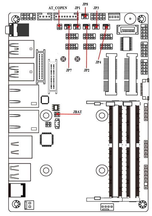
11 Jumper Positions: 6
12 Jumper Jumper Name Description JP1 COM1 Header Pin9 Function Select 4-pin Block JP2 COM2 Header Pin9 Function Select 4-Pin Block JP3 COM3 Header Pin9 Function Select 4-Pin Block JP4 COM4 Header Pin9 Function Select 4-Pin Block JP7 LVDS Header VCC 3.3V/5V/12V Select 4-Pin Block JP8 LVDS INVERTER Backlight 5V/12V Select 4-Pin Block AT_COPEN Pin (1&2): ATX Mode / AT Mode Select 4-Pin Block Pin(3&4):Case Open Message Display Function JBAT Pin (1&2): Clear CMOS RAM Function Setting Pin(3&4): Flash Descriptor Security Override 4-Pin Block Connectors Connector Name DCIN 9V~24V DC in System Power Jack ATX2P Internal 9V~24V System DC in Power Connector USB20 USB 2.0 Port Connector x2 DP_HDMI Top: Display Port Connector Bottom: HDMI Port Connector LAN1/LAN2 RJ-45 LAN Port Connector x2 USB30/USB31 USB 3.0 Port Connector x 4 LINE_OUT Audio Line-Out Connector SATA SATAIII Connector SATAPWR SATA Power out Connector CPUFAN CPUFAN Connector 7
13 Headers Header Name Description FP_AUDIO Front Panel Audio Header 9-pin Block SPEAK_CON 3W Amplifier Header 4-pin Block JW_FP Front Panel Header(PWR LED/ HDD 9-pin Block LED/Power Button /Reset) FP_USB20/ USB 2.0 Header 9-pin Block FP_USB21 FP_USB USB 2.0 Header 4-pin Block SMBUS SMBUS Header 5-pin Block PS2KBMS PS/2 Keyboard & Mouse Header 6-pin Block GPIO GPIO Header 10-pin Block COM1 RS232/422/485 Serial Port Header 9-pin Block COM2/3/4/5/6 RS232 Serial Port Header 9-pin Block LAN_LED LAN Activity LED Header 4-pin Block INVERTER LVDS Inverter Header 8-pin Block LVDS LVDS Header 30-pin Block EDP 4-lane EDP Header 40-pin Block 8
14 Chapter 2 Hardware Installation 2-1 Jumper Setting JP1 (4-pin): COM1 Header Pin9 Function Select JP1 COM1 Header Pin C losed: Pin9=RING (Default); C losed: Pin9=+5V; Closed: Pin9=+12V. JP2 (4-pin): COM2 Header Pin9 Function Select JP2 COM2 Header Pin Closed: Pin9= RING (Default); Closed: Pin9=+5V; Closed: Pin9=+12V. 9
15 JP3 (4-pin): COM3 Header Pin9 Function Select JP3 COM3 Header Pin Closed: Pin9= RING (Default); Closed: Pin9=+5V; Closed: Pin9=+12V. JP4 (4-pin): COM4 Header Pin9 Function Select JP4 COM4 Header Pin Closed: Pin9= RING (Default); Closed: Pin9=+5V; Closed: Pin9=+12V. 10
16 JP7 (4-pin): LVDS/eDP VCC 3.3V/5V/12V Select JP7 LVDS VCC Closed: VCC = 3.3V 3-4 Closed: VCC = 5V; Closed: VCC = 12V; JP8 (3-pin): LVDS/eDP INVERTER Backlight 5V/12V Select JP8 LVDS Backlight Closed: VCC = 5V; 3-4 Closed: VCC = 12V; Closed: VCC = DC-in. *Note: The maximum current carried is 1A. 11
17 Pin(1-2) of AT_COPEN (4-pin): ATX Mode/AT Mode Select Pin(1-2) of AT_COPEN ATX/AT Mode Select Pin Open: ATX Mode Selected(Default); ; Pin Closed: AT Mode Selected. *ATX Mode Selected: Press power button to power on after power input ready; AT Mode Selected: Directly power on as power input ready. Pin(3-4) of AT_COPEN (4-pin): Case Open Message Display Function Select Pin(3-4) of AT_COPEN Case Open Dectect Select Pin Open: Normal(Default); ; Pin Closed: Case Open Function. Selected(One Touch). Pin (3&4) Closed: When Case open function pin short to GND, the Case open function was detected. When Used, needs to enter BIOS and enable Case Open Detect function. In this case if your case is removed, next time when you restart your computer, a message will be displayed on screen to inform you of this. 12
18 Pin (1-2) of JBAT (4-pin): Clear CMOS RAM Settings Pin(1-2) of JBAT Clear CMOS Pin1 1-2 Open: Normal(Default); ; Pin1 1-2 Closed: Clear CMOS(One Touch). Pin(3-4)of JBAT (4-pin): Flash Descriptor Security Override Pin(3-4) of JBAT Flash Descriptor Security Override Pin1 3-4 Open: Enable security measures defined in the Flash Descriptor (Default); Pin1 3-4 Closed: Disable Flash Descriptor security measures (override). 13
19 2-2 Connectors and Headers Connectors (1) Rear I/O Connectors Line-out Port USB 3.0 Ports LAN1 RJ-45 LAN Port Display Port 9V~24V DC-in Power Jack Icon Name Function 9V~24V DC-in Power Jack HDMI Port LAN2 USB 2.0 Ports RJ-45 LAN Port For user to connect compatible power adapter to provide power supply for the system. USB 2.0 Port USB 3.0 Port Display Port HDMI Port RJ-45 LAN Port Line-Out Port To connect USB keyboard, mouse or other devices compatible with USB specification. To connect USB keyboard, mouse or other devices compatible with USB specification. USB 3.0 ports supports up to 5Gbps data transfer rate. To the system to corresponding display device with compatible DP cable. To connect display device that support HDMI specification. This connector is standard RJ-45 LAN jack for Network connection. For user to connect external speaker, earphones, etc. to transfer system audio output. 14
 SATA (7-pin): SATAIII Port connector The onboard SATA port is high-speed SATAIII port that supports 6GB/s")
20 (2) ATX2P (2-pin Block): Internal 9V~24V DC-in Power Connector Pin 1 Pin. Definition 1 +9V~+ 24V DC_IN 2 GND (3) SATA (7-pin): SATAIII Port connector The onboard SATA port is high-speed SATAIII port that supports 6GB/s transfer rate. Pin No. Definition 1 GND 2 TXP 3 TXN 4 GND 5 RXN 6 RXP 7 GND 15
21 (4) SATAPWR (4-pin): SATA Power Out Connector Pin 1 +12V GND GND +5V Warning: Make sure that Pin-1 of compatible SATA Power connector is inserted into corresponding Pin-1 of SATAPW to avoid possible damage to the board and hard disk driver! (5) CPUFAN (4-pin): CPUFAN Connector Pin1 +12V Fan Power GND Fan Speed Control 16
22 2-2-2 Headers (1) FP_AUDIO (9-pin): Line-Out, MIC-In Header This header connects to Front Panel Line-out, MIC-In connector with cable. LINE_OUT_JD MIC_JD DETECT GND 2 Pin 1 LINE OUT-L SENSE LINE OUT-R MIC2-R MIC2-L (2) SPEAK_CON (4-pin block): Speaker Header Pin1 Pin No. Definition 1 L- 2 L+ 3 R+ 4 R- 17
23 (3) JW_FP (9-pin): Front Panel Header GND PWRBTN PWR LED- PWR LED+ 2 Pin 1 VCC RSTSW GND HDD LED- HDD LED+ (4) FP_USB20/F_USB21 (9-pin): USB 2.0 Port Header NC GND +DATA -DATA VCC 2 Pin 1 GND +DATA -DATA VCC 18
24 (5) FP_ USB(4-pin): USB 2.0 Port Header GND +DATA -DATA VCC Pin 1 (6) SMBUS (5-Pin): SM BUS Header VCC3 GND NC SMBUS_DATA SMBUS_CLK Pin 1 19
25 (7) PS2KBMS (6-pin): PS2 Keyboard & Mouse Header MS_DATA MS_CLK GND KB_CLK KB_DATA 5VSB Pin 1 (8) GPIO (10-pin): GPIO Header VCC GPIO_47 GPIO_45 GPIO_43 GPIO_41 2 Pin1 GND GPIO_46 GPIO_44 GPIO_42 GPIO_40 20
 (COM1) Pin 1 DCD TX- DATA- Pin 2 RXD TX+ DATA+ Pin 3 TXD RX+ NC Pin 4 DTR RX- NC Pin 5 GND GND GND Pin 6 DSR NC NC Pin 7 RTS NC NC Pin 8 CTS NC NC Pin 9 RI NC NC *Notice:")
26 (9) COM1/2/3/4/5/6 (9-pin): Serial Port Header COM1 (9-pin): RS232/422/485 Serial Port Header COM2/3/4/5/6 (9-pin): RS232 Serial Port Header Pin1 Pin NO. RS232 *RS422 *RS485 (COM1) (COM1) Pin 1 DCD TX- DATA- Pin 2 RXD TX+ DATA+ Pin 3 TXD RX+ NC Pin 4 DTR RX- NC Pin 5 GND GND GND Pin 6 DSR NC NC Pin 7 RTS NC NC Pin 8 CTS NC NC Pin 9 RI NC NC *Notice: COM1 header can function as RS232/422/485 port. In normal settings COM1 functions as RS232 port. With compatible COM cable COM1 can function as RS422 or RS 485 port. User also needs to go to BIOS to set Transmission Mode Select for COM1 as [RS422] or [RS485] for boards that support RS422/485 function before connecting compatible COM cable to COM1 header. 21
27 (10) LAN_LED (4-pin): LAN Activity LED Header LAN2LED- LAN1LED- 2 Pin 1 LAN2LED+ LAN1LED+ (11) INVERTER (8-pin): LVDS/eDP Inverter Header Pin1 Pin No. Definition 1 Backlight Enable 2 Backlight PWM 3 Backlight VCC 4 Backlight VCC 5 GND 6 GND 7 Backlight Brightness Up SW 8 Backlight Brightness Down SW Warning! Find Pin-1 location of the inverter and make sure that the installation direction is correct! Otherwise serious harm will occur to the board/display panel!! 22
28 (12) LVDS (30-pin): 24-bit Dual Channel LVDS Header Pin 1 Pin2 Pin NO. Pin Define Pin NO. Pin Define Pin 1 LVDSB_DATAN3 Pin 2 LVDSB_DATAP3 Pin 3 LVDS_CLKBN Pin 4 LVDS_CLKBP Pin 5 LVDSB_DATAN2 Pin 6 LVDSB_DATAP2 Pin 7 LVDSB_DATAN1 Pin 8 LVDSB_DATAP1 Pin 9 LVDSB_DATAN0 Pin 10 LVDSB_DATAP0 Pin 11 NC/DDC_DATA Pin 12 NC/DDC_CLK Pin 13 GND Pin 14 GND Pin 15 GND Pin 16 GND Pin 17 LVDSA_DATAP3 Pin 18 LVDSA_DATAN3 Pin 19 LVDS_CLKAP Pin 20 LVDS_CLKAN Pin 21 LVDSA_DATAP2 Pin 22 LVDSA_DATAN2 Pin 23 LVDSA_DATAP1 Pin 24 LVDSA_DATAN1 Pin 25 LVDSA_DATAP0 Pin 26 LVDSA_DATAN0 Pin 27 VLCD Pin 28 VLCD Pin 29 VLCD Pin 30 VLCD 23
29 (13) EDP (40-pin): 4-lane edp Header Pin21 Pin 1 Pin NO. Pin Define Pin NO. Pin Define Pin 1 NC Pin 21 NC Pin 2 GND Pin 22 NC Pin 3 Lane3_N Pin 23 GND Pin 4 Lane3_P Pin 24 GND Pin 5 GND Pin 25 GND Pin 6 Lane2_N Pin 26 GND Pin 7 Lane2_P Pin 27 HPD Pin 8 GND Pin 28 GND Pin 9 Lane1_N Pin 29 GND Pin 10 Lane1_P Pin 30 GND Pin 11 GND Pin 31 GND Pin 12 Lane0_N Pin 32 BL_ENABLE Pin 13 Lane0_P Pin 33 BL_PWM_DIM Pin 14 GND Pin 34 NC Pin 15 AUX_CH_P Pin 35 NC Pin 16 AUX_CH_N Pin 36 BL_PWR Pin 17 GND Pin 37 BL_PWR Pin 18 LCD_VCC Pin 38 BL_PWR Pin 19 LCD_VCC Pin 39 BL_PWR Pin 20 LCD_VCC Pin 40 NC 24
30 Notice! Chapter 3 Introducing BIOS The BIOS options in this manual are for reference only. Different configurations may lead to difference in BIOS screen and BIOS screens in manuals are usually the first BIOS version when the board is released and may be different from your purchased motherboard. Users are welcome to download the latest BIOS version form our official website. The BIOS is a program located on a Flash Memory on the motherboard. This program is a bridge between motherboard and operating system. When you start the computer, the BIOS program will gain control. The BIOS first operates an auto-diagnostic test called POST (power on self test) for all the necessary hardware, it detects the entire hardware device and configures the parameters of the hardware synchronization. Only when these tasks are completed done it gives up control of the computer to operating system (OS). Since the BIOS is the only channel for hardware and software to communicate, it is the key factor for system stability, and in ensuring that your system performance as its best. 3-1 Entering Setup Power on the computer and by pressing <Del> immediately allows you to enter Setup. If the message disappears before your respond and you still wish to enter Setup, restart the system to try again by turning it OFF then ON or pressing the RESET button on the system case. You may also restart by simultaneously pressing <Ctrl>, <Alt> and <Delete> keys. If you do not press the keys at the correct time and the system does not boot, an error message will be displayed and you will again be asked to Press <Del> to enter Setup; press < F7> to enter pop-up Boot menu. 25
31 3-2 BIOS Menu Screen The following diagram show a general BIOS menu screen: Menu Bar General Help Items Menu Items Current Setting Value Function Keys 3-3 Function Keys In the above BIOS Setup main menu of, you can see several options. We will explain these options step by step in the following pages of this chapter, but let us first see a short description of the function keys you may use here: Press fi (left, right) to select screen; Press fl (up, down) to choose, in the main menu, the option you want to confirm or to modify. Press <Enter> to select. 26
32 Press <+>/< > keys when you want to modify the BIOS parameters for the active option. [F1]: General help. [F2]: Previous value. [F3]: Optimized defaults. [F4]: Save & Exit. Press <Esc> to quit the BIOS Setup. 3-4 Getting Help Main Menu The on-line description of the highlighted setup function is displayed at the top right corner the screen. Status Page Setup Menu/Option Page Setup Menu Press [F1] to pop up a small help window that describes the appropriate keys to use and the possible selections for the highlighted item. To exit the Help Window, press <Esc>. 3-5 Menu Bars There are six menu bars on top of BIOS screen: Main To change system basic configuration Advanced To change system advanced configuration Chipset To change chipset configuration Security Password settings Boot To change boot settings Save & Exit Save setting, loading and exit options. User can press the right or left arrow key on the keyboard to switch from menu bar. The selected one is highlighted. 27
33 3-6 Main Menu Main menu screen includes some basic system information. Highlight the item and then use the <+> or <-> and numerical keyboard keys to select the value you want in each item. System Date Set the date. Please use [Tab] to switch between data elements. System Time Set the time. Please use [Tab] to switch between time elements. 28
![3-7 Advanced Menu CPU Configuration Press [Enter] to view current CPU configuration and make settings for the following sub-items: Hyper-Threading The optional settings: [Disabled]; [Enabled].](/docs-images/95/126059789/images/34-0.jpg "When set as [Disabled] only one thread per enabled core is enabled. [Enabled]: for Windows and Linux (OS optimized for Hyper-Threading Technology).")
34 3-7 Advanced Menu CPU Configuration Press [Enter] to view current CPU configuration and make settings for the following sub-items: Hyper-Threading The optional settings: [Disabled]; [Enabled]. When set as [Disabled] only one thread per enabled core is enabled. [Enabled]: for Windows and Linux (OS optimized for Hyper-Threading Technology). [Disabled]: for other OS (OS optimized not for Hyper-Threading Technology). *Note: Hyper-Threading item may or may not show up, depending on different CPU. Intel Virtualization Technology The optional settings: [Enabled]; [Disabled]. When set as [Enabled], a VMM can utilize the additional hardware capabilities 29
35 provided by Vanderpool Technology. Hardware Prefetcher Use this item to turn on/off the MLC streamer prefecher. The optional settings: [Disabled]; [Enabled]. Adjacent Cache Line Prefetch Use this item to turn on/off prefeching of adjacent cache lines. The optional settings: [Disabled]; [Enabled]. Intel(R) SpeedStep(tm) This item allows more than two frequency ranges to be supported. The optional settings: [Disabled]; [Enabled]. CPU C States Use this item to enable or disable CPU power management. This item allows CPU to go to C states when it s not 100% utilized. The optional settings: [Disabled]; [Enabled]. Package C State Limit Use this item to select the maximum Package C State limit setting. The optional settings are: [C0/C1]; [C2]; [C3]; [C6]; [C7]; [C7s]; [C8]; [C9]; [C10]; [CPU default]; [AUTO]. [CPU Default]: Leaves to factory default value. [AUTO]: Initializes to deepest available Package C State Limit. 4 SATA Configuration Press [Enter] to make settings for the following sub-items: SATA Configuration(s) SATA Controller The optional settings are: [Enabled]; [Disabled]. When set as [Enabled], the following items shall appear: SATA Mode Selection The default setting is: [AHCI]. The optional settings are: [AHCI]. SATA 30
36 Port The optional settings: [Disabled]; [Enabled]. Use this item to enable or disable each SATA port. Hot Plug The optional settings: [Disabled]; [Enabled]. msata Port The optional settings: [Disabled]; [Enabled]. Use this item to enable or disable device connected to MSATA slot. 4 PCH-FW Configuration Press [Enter] to view ME information and make settings in the following sub-items: TPM Device Selection Use this item to select TPM device. The optional settings: [dtpm]; [PTT]. The default setting is: [dtpm]. [PTT]: Enable PTT in SkuMgr. [dtpm]: Disable PTT in SkuMgr. Warnning!! PTT/dTPM will be disabled and all data saved on it will be lost! 4 Firmware Update Configuration Press [Enter] to make settings for ME FW Image RE-Flash. ME FW Image Re-Flash Use this item to enable or disable ME FW Image Re-Flash function. The optional settings: [Disabled]; [Enabled]. * In the case that user needs to update ME firmware, user should set ME FW Image Re-Flash as [Enabled], save the settings and exit. The system will turn off and reboot after 4 seconds. If the user goes to BIOS screen again will find this item is set again as [Disabled], but user can still re-flash to update firmware next time. 31
37 AMT Configuration Use this item to configure Active Management Technology parameters. Press [Enter] to make settings for the following sub-items: Intel AMT Use this item to enable or disable Intel Active Management Technology BIOS extension. Hide Un-Configure ME Confirmation Prompt Use this function to enable or disable Hide Un-Configure ME without password Configuration Prompt function. MEBx Debug Message Output Use this function to enable or disable MEBx Debug Message Output function. Un-Configure ME Use this function to enable or disable Un-Configure ME without password function. ASF Use this item to enable or disable Alert Specification Format. Activate Remote Assistance Process Use this item to enable or disable Trigger CIRA boot function. USB Configure Use this item to enable or disable USB configure function. PET Progress Use this item to enable or disable PET events progress to receive PET events or not. WatchDog Use this item to enable or disable WatchDog Timer. *When set as [Enabled], the following sub-items shall appear: OS Timer Use this item to set OS watch dog timer. BIOS Timer Use this item to set BIOS watch dog timer. 4 Trusted Computing 32
38 Press [Enter] to enable or disable Security Device Support. Configuration Security Device Support Use this item to enable or disable BIOS support for security device. TCG EFI protocol and INT1A interface will not be available. The optional settings: [Disabled]; [Enabled]. 4 ACPI Settings Press [Enter] to make settings for the following sub-item: ACPI Settings ACPI Sleep State Use this item to select the highest ACPI sleep state the system will enter when the suspend button is pressed. The optional settings are: [Suspend Disabled]; [S3 (Suspend to RAM)]. 4 Wake-up Function Settings Press [Enter] to make settings for the following sub-items: Wake-up System with Fixed Time Use this item to enable or disable system wake on alarm event. The optional settings: [Disabled]; [Enabled]. When set as [Enabled], system will wake on the hour/min/sec specified. Wake-up System with Dynamic Time Use this item to enable or disable system wake on alarm event. System will wake on the current time + Increase minutes. The optional settings: [Disabled]; [Enabled]. When set as [Enabled], system will wake on the current time + increased minute(s). PS2 KB/MS Wake-up The optional settings: [Disabled]; [Enabled]. Use this item to enable or disable PS2 KB/MS wake-up from S3/S4/S5. 33
39 * Note: This function is supported when ERP Support is set as [Disabled]. USB S3/S4 Wake-up Use this item to enable or disable USB S3/S4 wakeup. * Note: This function is supported when ERP Support is set as [Disabled]. USB S5 Power Use this item to enable or disable USB power after power shutdown. *This function is supported when ERP Support is set as [Disabled]. Internal USB Port S5 Power The optional settings: [Enabled]; [Disabled]. Use this item to enable or disable USB power after System shutdown. * Note: This function is supported when ERP Support is set as [Disabled]. 4 Super I/O Configuration Press [Enter] to make settings for the following sub-items: Super IO Configuration ERP Support The optional settings: [Disabled]; [Auto]. This item should be set as [Disabled] if you wish to have all active wake-up functions. Serial Port 1 Configuration Press [Enter] to make settings for the following items: Serial Port Use this item to enable or disable serial port (COM). Change Settings Use this item to select an optimal setting for super IO device. Transmission Mode Select The optional settings are: [RS422]; [RS232]; [RS485]. Mode Speed Select The optional settings are: [RS232/RS422/RS485=250kbps]; [RS232=1Mbps, RS422/RS485=10Mbps]. 34
40 Serial Port FIFO Mode The optional settings are: [16-Byte FIFO]; [32-Byte FIFO]; [64-Byte FIFO]; [128-Byte FIFO]. Serial Port 2 Configuration/ Serial Port 3 Configuration/Serial Port 4 Configuration/ Serial Port 5 Configuration/ Serial Port 6 Configuration Press [Enter] to make settings for the following sub-items: Serial Port Use this item to enable or disable serial port (COM). Change Settings Use this item to select an optimal setting for super IO device. Serial Port FIFO Mode The optional settings are: [16-Byte FIFO]; [32-Byte FIFO]; [64-Byte FIFO]; [128-Byte FIFO]. WatchDog Reset Timer Use this item to enable or disable WDT reset function. The optional settings: [Disabled]; [Enabled]. When set as [Enabled], the following sub-items shall appear: WatchDog Reset Timer Value User can set a value in the range of [4] to [255]. WatchDog Reset Timer Unit The optional settings are: [Sec.]; [Min.]. ATX Power Emulate AT Power This item support Emulate AT power function, MB power On/Off control by power supply. Use needs to select AT or ATX Mode on MB jumper at first (refer to Page 11, Pin(1-2) of AT_COPEN jumper for ATX Mode / AT Mode Select). Case Open Detect Use this item to detect case has already open or not, show message in POST. 4 PC Health Status Press [Enter] to view current hardware health status, set shutdown temperature, or 35
41 make further settings in SmartFAN Configuration. 4 SmartFAN Configuration Press [Enter] to make settings for SmartFAN Configuration: CPUFAN Smart Mode The optional settings: [Disabled]; [Enabled]. When set as [Enabled], the following sub-items shall appear: CPUFAN Full-Speed Temperature Use this item to set CPUFAN full speed temperature. Fan will run at full speed when above the preset temperature. CPUFAN Full-Speed Duty Use this item to set CPUFAN full speed duty. Fan will run at full speed when above the pre-set duty. CPUFAN Idle-Speed Temperature Use this item to set CPUFAN idle speed temperature. Fan will run at idle speed when below the pre-set temperature. CPUFAN Idle-Speed Duty Use this item to set CPUFAN idle speed duty. Fan will run at idle speed when below the pre-set duty. Shutdown Temperature Configuration Use this item to select system shutdown temperature. The optional settings are: [Disabled]; [70 o C/156 o F]; [75 o C/164 o F]; [80 o C/172 o F]; [85 o C/180 o F]; [90 o C/188 o F]. 4 Serial Port Console Redirection COM1 Console Redirection Use this item to enable or disable COM1 Console Redirection. The optional settings are: [Disabled]; [Enabled]. When set as [Enabled], user can make further settings in the Console 36
42 Redirection Settings screen: 4 Console Redirection Settings The settings specify how the host computer and the remote computer (which the user is using) will exchange data. Both computers should have the same or compatible settings. Press [Enter] to make settings for the following sub-items. Terminal Type The optional settings are: [VT100]; [VT100+]; [VT-UTF8]; [ANSI]. Bits per second The optional settings are: [9600]; [19200]; [38400]; [57600]; [115200]. Data Bits The optional settings are: [7]; [8]. Parity The optional settings are: [None]; [Even]; [Odd];[Mark]; [Space]. Stop Bits The optional settings are: [1]; [2]. Flow Control The optional settings are: [None]; [Hardware RTS/CTS]. VT-UTF8 Combo Key Support The optional settings are: [Disabled]; [Enabled]. Recorder Mode The optional settings are: [Disabled]; [Enabled]. Resolution 100x31 The optional settings are:[disabled]; [Enabled]. Legacy OS Redirection Resolution The optional settings are: [80x24]; [80x25]. Putty Keypad The optional settings are: [VT100]; [LINUX]; [XTERMR6]; [SCO]; [ESCN]; [VT400]. Redirection After BIOS POST The optional settings are: [Always Enable]; [BootLoader]. 37
43 Serial Port for Out-of-Band Management/ Windows Emergency Management Services (EMS) Console Redirection The optional settings: [Disabled]; [Enabled]. When set as [Enabled], user can make further settings in Console Redirection Settings screen: 4 Console Redirection Settings The settings specify how the host computer and the remote computer (which the user is using) will exchange data. Both computers should have the same or compatible settings. Press [Enter] to make settings for the following sub-items. Out-of-Band Mgmt Port The optional settings are: [COM1]; [COM1(Pci Bus0, Dev0, Func0) (Disabled)]. Terminal Type The optional settings are: [VT100]; [VT100+]; [VT-UTF8]; [ANSI]. Bits per second The optional settings are: [9600]; [19200]; [57600]; [115200]. Flow Control The optional settings are: [None]; [Hardware RTS/CTS]; [Software Xon/Xoff]. Data Bits The default setting is: [8]. *This item may or may not show up, depending on different configuration. Parity The default setting is: [None]. *This item may or may not show up, depending on different configuration. Stop Bits The default setting is: [1]. *This item may or may not show up, depending on different configuration. 38
44 4 Network Stack Configuration Press [Enter] to go to Network Stack screen to make further settings. Network Stack The optional settings are: [Enabled]; [Disabled]. When set as [Enabled], the following sub-items shall appear: Ipv4 PXE Support The optional settings are: [Disabled]; [Enabled]. Use this item to enable Ipv4 HTTP Boot Support. When set as [Disabled], Ipv4 PXE boot option will not be created. Ipv4 HTTP Support The optional settings are: [Disabled]; [Enabled]. Use this item to enable Ipv4 PXE Boot Support. When set as [Disabled], Ipv4 HTTP boot option will not be created. Ipv6 PXE Support The optional settings are: [Disabled]; [Enabled]. Use this item to enable Ipv6 HTTP Boot Support. When set as [Disabled], Ipv6 PXE boot option will not be created. Ipv6 HTTP Support The optional settings are: [Disabled]; [Enabled]. Use this item to enable Ipv6 PXE Boot Support. When set as [Disabled], Ipv6 HTTP boot option will not be created. PXE boot wait time Use this item to set wait time to press [ESC] key to abort the PXE boot. Media Detect Count Use this item to set number of times presence of media will be checked. The optional settings range from [1] to [50]. 4 CSM Configuration Press [Enter] to make settings for the following sub-items: Option ROM execution Network 39
45 This item controls the execution of UEFI and legacy PXE OpROM. The optional settings are: [Do not launch]; [Legacy]. Storage This item controls the execution of UEFI and Legacy Storage OpROM. The optional settings are: [Do not launch]; [UEFI]; [Legacy]. Other PCI devices This item determines OpROM execution policy for devices other than Network, storage or video. The optional settings are: [Do not launch]; [UEFI]; [Legacy]. 4 USB Configuration Press [Enter] to make settings for the following sub-items: USB Configuration Legacy USB Support The optional settings are: [Enabled]; [Disabled]; [Auto]. [Enabled]: To enable legacy USB support. [Disabled]: To keep USB devices available only for EFI specification, [Auto]: To disable legacy support if no USB devices are connected. XHCI Hand-off This is a workaround for OSes without XHCI hand-off support. The XHCI ownership change should be claimed by XHCI driver. The optional settings are: [Enabled]; [Disabled]. USB Mass Storage Driver Support The optional settings are: [Disabled]; [Enabled]. USB Hardware Delays and Time-outs: USB Transfer Time-out Use this item to set the time-out value for control, bulk, and interrupt transfers. The optional settings are: [1 sec]; [5 sec]; [10 sec]; [20 sec]. Device Reset Time-out Use this item to set USB mass storage device start unit command time-out. The optional settings are: [10 sec]; [20 sec]; [30 sec]; [40 sec]. 40
46 Device Power-up Delay Use this item to set maximum time the device will take before it properly reports itself to the host controller. The optional settings: [Auto]; [Manual]. Auto uses default value: for a root port it is 100 ms, for a hub port the delay is taken from hub descriptor. Select [Manual] you can set value for the following sub-item: Device Power-up Delay in Seconds. Device Power-up Delay in Seconds The delay range is from [1] to [40] seconds, in one second increments. 4 Intel(R) I211 Gigabit Network Connection -XX:XX:XX:XX:XX:XX/ Intel(R) Ethernet Connection (3) I219-LM -XX:XX:XX:XX:XX:XX This item gives Intel gigabit ethernet controller basic MAC address information. 41
![3-8 Chipset Menu 4 System Agent (SA) Configuration Press [Enter] to make settings for the following sub-items: VT-d The optional settings are: [Enabled]; [Disabled].](/docs-images/95/126059789/images/47-0.jpg "Graphics Configuration Press [Enter] to make further settings for Graphics Configuration. Graphics Configuration GTT Size The optional settings are: [2MB]; [4MB]; [8MB].")
47 3-8 Chipset Menu 4 System Agent (SA) Configuration Press [Enter] to make settings for the following sub-items: VT-d The optional settings are: [Enabled]; [Disabled]. Graphics Configuration Press [Enter] to make further settings for Graphics Configuration. Graphics Configuration GTT Size The optional settings are: [2MB]; [4MB]; [8MB]. Aperture Size The optional settings are: [128MB]; [256MB]; [512MB]; [1024MB]. DVMT Pre-Allocated Use this item to select DVMT 5.0 pre-allocated (fixed) graphics memory size used 42
48 by the internal graphics device. The optional settings are: [32M]; [64M]; [96M]; [128M]; [160M]; [192M]; [224M]; [256M]; [288M]; [320M]; [352M]; [384M]; [416M]; [448M]; [480M]; [512M]; [1024M]; [1536M]; [2048M]; [4M]; [8M]; [12M]; [16M]; [20M]; [24M]; [28M] [32M/F7]; [36M]; [40M]; [44M]; [48M]; [52M]; [56M]; [60M]. DVMT Total Gfx Mem Use this item to select DVMT 5.0 total graphics memory size used by the internal graphics device. The optional settings are: [128M]; [256M]; [MAX]. Primary IGFX Boot Display Use this item to select the video device which will be activated during POST. This has no effect if external graphics present. Secondary boot display selection will appear based on your selection. The optional settings are: [VBIOS Default]; [DP]; [HDMI]; [edp/lvds]. Active LVDS The optional settings are: [LVDS]; [edp]. When set as [LVDS], user can make further settings in screen: Backlight Control The optional settings are: [PWM Inverted]; [PWM Normal]. Panel Type Use this item to manually select LCD panel type used by internal graphics device by selecting the appropriate setup item. The optional setting are: [800x bit Single]; [800x 60018bit Single]; [800x bit Single]; [1024 x 60018bit Single]; [1024 x bit Single]; [1024 x bit Single]; [1280 x bit Single]; [1280 x bit Single]; [1280 x bit Single]; [1366 x bit Single]; [1366 x bit Single]; [1440 x bit Dual]; [1440 x bit Dual]; [1280 x bit Dual]; [1680 x bit Dual]; [1920 x bit Dual]. 43
49 LVDS FW Write Protect This item supports LVDS FW update & protection. The optional settings are: [Enabled]; [Disabled]. Memory Configuration Press [Enter] to view brief information for the working memory module. PCH-IO Configuration Press [Enter] to make settings for the following sub-items: USB Controller The optional settings are: [Disabled]; [Enabled]. HD Audio The optional settings are: [Disabled]; [Enabled]; [Auto]. Onboard Lan1 Controller Use this item to enable or disable LAN1 NIC. When set as [Enabled], user can make further settings in Wake on LAN item: Wake on LAN Use this item to enable or disable integrated LAN to wake the system. The optional settings are: [Enabled]; [Disabled]. Onboard Lan2 Controller Use this item to enable or disable LAN2 device or controller. MPEST Slot Use this item to enable or disable device or controller installed on MPEST slot. The optional settings are: [Disabled]; [Enabled]. Speed The optional settings are: [Auto]; [Gen1]; [Gen2]; [Gen3]. MPE Slot Use this item to enable or disable device or controller installed on MPE slot. The optional settings are: [Disabled]; [Enabled]. Speed The optional settings are: [Auto]; [Gen1]; [Gen2]; [Gen3]. System State after Power Failure 44

50 Use this item to specify what state to go to when power re-applied after a power failure (G3 state). The optional settings are: [Always Off]; [Always On]; [Former State]. 3-9 Security Menu Security menu allow users to change administrator password and user password settings. 45
51 3-10 Boot Menu Boot Configuration Setup Prompt Timeout Use this item to set number of seconds to wait for setup activation key. Bootup Numlock State Use this item to select keyboard numlock state. The optional settings are: [On]; [Off]. Quiet Boot The optional settings are: [Disabled]; [Enabled]. Boot Option Priorities Boot Option #1/ Boot Option #2 Use this item to decide system boot order from available options. 46
52 UEFI Boot The optional settings are: [Disabled]; [Enabled]. [Disabled]: Disable all UEFI boot options. [Enabled]: Enable all UEFI boot options Save & Exit Menu Save Changes and Reset This item allows user to reset the system after saving the changes. Discard Changes and Reset This item allows user to reset the system without saving any changes. Restore Defaults Use this item to restore /load default values for all the setup options. Save as User Defaults Use this item to save the changes done so far as user defaults. 47
53 Restore User Defaults Use this item to restore the user defaults to all the setup options. Boot Override UEFI: Built-in EFI Shell Press this item to select the device as boot disk after save configuration and reset. Launch EFI Shell from filesystem device This item is used for attempts to launch EFI shell application from one of the available file system devices. 48
NU792 Series. User s Manual
 NU792 Series User s Manual NO.G03-NU792-F Revision: 2.0 Release date: May 23, 2018 Trademark: * Specifications and Information contained in this documentation are furnished for information use only, and
Technical Manual Of Intel Braswell Series CPU Based IPC M/B
 Technical Manual Of Intel Braswell Series CPU Based IPC M/B NO. G03-NF531-F Revision: 1.0 Release date: April 14, 2016 Trademark: * Specifications and Information contained in this documentation are furnished
Technical Manual Of Intel Haswell/Broadwell Series CPU Based 3.5 SBC
 Technical Manual Of Intel Haswell/Broadwell Series CPU Based 3.5 SBC NO. G03-NF3E-F Revision: 1.0 Release date: January 12, 2015 Trademark: * Specifications and Information contained in this documentation
Technical Manual Of Intel Braswell Series CPU Based SBC
 Technical Manual Of Intel Braswell Series CPU Based SBC NO.G03-NP591-F Revision: 1.0 Release date: November 1, 015 Trademark: * Specifications and Information contained in this documentation are furnished
Technical Manual Of Intel Bay Trail Series CPU Based 3.5 SBC
 Technical Manual Of Intel Bay Trail Series CPU Based 3.5 SBC NO.G03-NF532-F Revision: 1.0 Release date: May 26, 2015 Trademark: * Specifications and Information contained in this documentation are furnished
TECHNICAL MANUAL. Intel Q170 Express Chipset. Based Mini-ITX M/B
 TECHNICAL MANUAL Of Intel Q170 Express Chipset Based Mini-ITX M/B NO. G03-NF594-F Revision: 1.0 Release date: March 17, 2016 Trademark: * Specifications and Information contained in this documentation
Technical Manual Of Intel Braswell Series CPU Based IPC M/B
 Technical Manual Of Intel Braswell Series CPU Based IPC M/B NO. G03-NF531M-F Revision: 1.0 Release date: July 5, 2018 Trademark: * Specifications and Information contained in this documentation are furnished
Technical Manual Of Intel Braswell Series CPU Based SBC
 Technical Manual Of Intel Braswell Series CPU Based SBC NO.G03-NU591-F Revision: 1.0 Release date: March 10, 2016 Trademark: * Specifications and Information contained in this documentation are furnished
NF697 Series User Manual
 NF697 Series User Manual NO. G03-NF697-F Revision: 2.0 Release date: August 14, 2017 Trademark: * Specifications and Information contained in this documentation are furnished for information use only,
TECHNICAL MANUAL. Intel H110 Express Chipset. Based Mini-ITX M/B
 TECHNICAL MANUAL Of Intel H110 Express Chipset Based Mini-ITX M/B NO. G03-NF693-F Revision: 3.0 Release date: July 19, 2017 Trademark: * Specifications and Information contained in this documentation are
Technical Manual Of Intel Braswell Series CPU Based Mini-ITX M/B
 Technical Manual Of Intel Braswell Series CPU Based Mini-ITX M/B NO.G03-NF596-F Revision: 1.0 Release date: December, 015 Trademark: * Specifications and Information contained in this documentation are
USER'S MANUAL Of Intel H110 Express Chipset Based
 USER'S MANUAL Of Intel H110 Express Chipset Based M/B for LGA 1151 Intel Core Processor G03-NMF691-F Rev: 2.0 Release date: February 13, 2017 Trademark: * Specifications and Information contained in this
Technical Manual Of Intel Apollo Lake Series CPU Based SBC
 Technical Manual Of Intel Apollo Lake Series CPU Based SBC NO.G03-NU691-F Revision: 1.0 Release date: April 12, 2018 Trademark: * Specifications and Information contained in this documentation are furnished
TECHNICAL MANUAL. Intel Braswell Series CPU. Based Mini-ITX M/B
 TECHNICAL MANUAL Of Intel Braswell Series CPU Based Mini-ITX M/B NO. G03-NC7C-F Revision: 1.0 Release date: November 8, 2017 Trademark: * Specifications and Information contained in this documentation
USER'S MANUAL Of Intel Q87 Express Chipset Based M/B for LGA 1150 Quad Core Ready Intel Core Processor
 USER'S MANUAL Of Intel Q87 Express Chipset Based M/B for LGA 1150 Quad Core Ready Intel Core Processor G03-NMF94RM-F Rev: 1.0 Release date: March 23, 2015 Trademark: * Specifications and Information contained
Technical Manual Of Intel Braswell Series CPU Based Mini-ITX M/B
 Technical Manual Of Intel Braswell Series CPU Based Mini-ITX M/B NO.G03-NF591-F Revision: 1.0 Release date: July 23, 2015 Trademark: * Specifications and Information contained in this documentation are
TECHNICAL MANUAL. Intel H61 Express Chipset. Based Mini-ITX M/B
 TECHNICAL MANUAL Of Intel H61 Express Chipset Based Mini-ITX M/B NO. G03-NC9FL-F Revision: 1.0 Release date: March 21, 2014 Trademark: * Specifications and Information contained in this documentation are
NF791 Series. User s Manual
 NF791 Series User s Manual G03-NF791-F Revision: 1.0 Release date: September 28, 2017 Trademark: * Specifications and Information contained in this documentation are furnished for information use only,
Technical Manual Of Intel Bay Trail Series CPU Based SBC
 Technical Manual Of Intel Bay Trail Series CPU Based SBC NO.G03-NU93-F Revision: 2.0 Release date: November 20, 2014 Trademark: * Specifications and Information contained in this documentation are furnished
Technical Manual Of Intel Bay Trail Series CPU Based Mini-ITX M/B
 Technical Manual Of Intel Bay Trail Series CPU Based Mini-ITX M/B NO.G03-NF9N-F Revision: 1.0 Release date: October 24, 2014 Trademark: * Specifications and Information contained in this documentation
TECHNICAL MANUAL Of Intel Cedar Trail-D & NM10 Chipset Based Mini-ITX M/B for ATOM Processor
 TECHNICAL MANUAL Of Intel Cedar Trail-D & NM10 Chipset Based Mini-ITX M/B for ATOM Processor NO.G03-NC9K-F Revision: 1.0 Release date: November, 2011 Trademark: * Specifications and Information contained
TECHNICAL MANUAL. Intel H110 Express Chipset. Based Mini-ITX M/B
 TECHNICAL MANUAL Of Intel H110 Express Chipset Based Mini-ITX M/B NO. G03-NF892-F Revision: 1.0 Release date: December 18, 2018 Trademark: * Specifications and Information contained in this documentation
TECHNICAL MANUAL. Intel H110 Express Chipset. Based Mini-ITX M/B
 TECHNICAL MANUAL Of Intel H110 Express Chipset Based Mini-ITX M/B NO. G03-NF595-F Revision: 1.0 Release date: January 5, 2016 Trademark: * Specifications and Information contained in this documentation
Technical Manual Of Intel Bay Trail Series CPU Based Mini-ITX M/B
 Technical Manual Of Intel Bay Trail Series CPU Based Mini-ITX M/B NO.G03-NF9HB-F Revision: 1.0 Release date: March 30, 2015 Trademark: * Specifications and Information contained in this documentation are
TECHNICAL MANUAL. Intel 1037U CPU + Intel NM70 Chipset. Based Mini-ITX M/B
 TECHNICAL MANUAL Of Intel 1037U CPU + Intel NM70 Chipset Based Mini-ITX M/B SYS7F880VGGA-OM Revision: 3.0 Release date: May 8, 2014 Trademark: * Specifications and Information contained in this documentation
TECHNICAL MANUAL. Intel Q170 Chipset. Based Mini-ITX M/B
 TECHNICAL MANUAL Of Intel Q170 Chipset Based Mini-ITX M/B NO.: G03-NF793-F Revision: 2.0 Release date: July 18, 2018 Trademark: * Specifications and Information contained in this documentation are furnished
NF792 Series. User s Manual
 NF792 Series User s Manual NO. G03-NF792-F Revision: 1.0 Release date: August 16, 2017 Trademark: * Specifications and Information contained in this documentation are furnished for information use only,
Technical Manual Of Intel Bay Trail Series CPU Based Mini-ITX M/B
 Technical Manual Of Intel Bay Trail Series CPU Based Mini-ITX M/B NO.G03-NF9M-F Revision: 4.0 Release date: July 20, 2017 Trademark: * Specifications and Information contained in this documentation are
TECHNICAL MANUAL. Intel Q87 Express Chipset. Based Mini-ITX M/B
 TECHNICAL MANUAL Of Intel Q87 Express Chipset Based Mini-ITX M/B NO. G03-NF9QU-F Revision: 1.0 Release date: October 14, 2014 Trademark: * Specifications and Information contained in this documentation
USER'S MANUAL Of Intel Q170 Express Chipset Based
 USER'S MANUAL Of Intel Q170 Express Chipset Based M/B for LGA 1151 Intel Core Processor No. G03-NAF591-F Rev: 1.0 Release date: November 26, 2015 Trademark: * Specifications and Information contained in
PPC-MB-8260AE (Intel Core i7/i5/i3/pentium/ Celeron LGA 1151 Mini-ITX with DP/VGA, 5 COM, 6 USB, Dual LAN, PCIe x4, Mini PCIe, DDR4) Startup Manual
 Startup Manual") PPC-MB-8260AE (Intel i7/i5/i3/pentium/ Celeron LGA 1151 Mini-ITX with DP/VGA, 5 COM, 6 USB, Dual LAN, PCIe x4, Mini PCIe, DDR4) Startup Manual Packing List Specifications Before card installation, ensure
PPC-MB-8260AE (Intel i7/i5/i3/pentium/ Celeron LGA 1151 Mini-ITX with DP/VGA, 5 COM, 6 USB, Dual LAN, PCIe x4, Mini PCIe, DDR4) Startup Manual Packing List Specifications Before card installation, ensure
Technical Manual Of Intel Cedar Trail Series CPU & NM10 Chipset Based 3.5 SBC
 Technical Manual Of Intel Cedar Trail Series CPU & NM10 Chipset Based 3.5 SBC F36W-2600B Revision: 2.0 Release date: April, 2012 Trademark: * Specifications and Information contained in this documentation
Technical Manual Of Intel Bay Trail Series CPU Based Mini-ITX M/B
 Technical Manual Of Intel Bay Trail Series CPU Based Mini-ITX M/B NO.G03-NF9T-F Revision:.0 Release date: July 6, 04 Trademark: * Specifications and Information contained in this documentation are furnished
1151 CPU, DP/ VGA, 5 COM, 6 USB,
 PPC-MB-8260AE Mini-ITX Motherboard with Intel Core i7/i5/i3/pentium /Celeron LGA 1151 CPU, DP/ VGA, 5 COM, 6 USB, Dual LAN, PCIe x4, and Mini PCIe Startup Manual Packing List Specifications Before card
TECHNICAL MANUAL. Intel Bay Trail Series CPU. Based Mini-ITX M/B
 TECHNICAL MANUAL Of Intel Bay Trail Series CPU Based Mini-ITX M/B SYS8F366VGGA-OM Revision:.0 Release date: December 6, 204 Trademark: * Specifications and Information contained in this documentation are
NF694/NF694L Series. User s Manual
 NF694/NF694L Series User s Manual NO. G03-NF694-F Revision: 1.0 Release date: March 16, 2018 Trademark: * Specifications and Information contained in this documentation are furnished for information use
TABLE OF CONTENT ENVIRONMENTAL SAFETY INSTRUCTION... iii ENVIRONMENTAL PROTECTION ANNOUCEMENT...iii USER S NOTICE... iv MANUAL REVISION INFORMATION...
 USER'S MANUAL Of Intel H81 Express Chipset Based M/B for LGA 1150 Quad Core Ready Intel Core Processor Rev: 1.0 Release date: May 30, 2016 Trademark: * Specifications and Information contained in this
TECHNICAL MANUAL. Intel Q67 Express Chipset. Based Mini-ITX M/B
 TECHNICAL MANUAL Of Intel Q67 Express Chipset Based Mini-ITX M/B NO. G03-NF9A-F Revision: 2.0 Release date: August, 2011 Trademark: * Specifications and Information contained in this documentation are
BIOS User Guide RACING P1A
 BIOS User Guide RACING P1A BIOS Update... 2 UEFI BIOS Setup... 6 1. Main Menu... 7 2. Advanced Menu... 8 3. Chipset Menu...14 4. Security Menu...20 5. Boot Menu...23 6. Exit Menu...25 BIOS Update The BIOS
Chapter 4 Using BIOS 1
 Chapter 1 Using BIOS 4 4.1 About the Setup Utility The computer uses the latest American Megatrends Inc. BIOS with support for Windows Plug and Play. The CMOS chip on the motherboard contains the ROM setup
TECHNICAL MANUAL Of AMD Hudson M1 Chipset Based. for AMD G-Series APU Mini-ITX M/B
 TECHNICAL MANUAL Of AMD Hudson M1 Chipset Based for AMD G-Series APU Mini-ITX M/B NO.G03-NF35-F Revision: 2.0 Release date: March, 2012 Trademark: * Specifications and Information contained in this documentation
TECHNICAL MANUAL Of Intel Cedar Trail-D & ICH10R Chipset Based Mini-ITX M/B for ATOM Processor
 TECHNICAL MANUAL Of Intel Cedar Trail-D & ICH10R Chipset Based Mini-ITX M/B for ATOM Processor NO. G03-NF9I-F Revision: 1.0 Release date: December 10, 01 Trademark: * Specifications and Information contained
Technical Manual Of Intel Bay Trail Series CPU Based Mini-ITX M/B
 Technical Manual Of Intel Bay Trail Series CPU Based Mini-ITX M/B NO.G03-NF9V-F Revision: 1.0 Release date: March 6, 2015 Trademark: * Specifications and Information contained in this documentation are
TECHNICAL MANUAL Of AMD Hudson E1/D1 Chipset Based. for AMD Brazos APU Mini-ITX M/B
 TECHNICAL MANUAL Of AMD Hudson E1/D1 Chipset Based for AMD Brazos APU Mini-ITX M/B NO.G03-NC85-F Revision:2.0 Release date: April, 2011 Trademark: * Specifications and Information contained in this documentation
Technical Manual Of Intel Denverton Series CPU Based SBC
 Technical Manual Of Intel Denverton Series CPU Based SBC NO.G03-NF699-F Revision: 1.0 Release date: July 12, 2018 Trademark: * Specifications and Information contained in this documentation are furnished
NF695 Series. User s Manual
 NF695 Series User s Manual NO. G03-NF695-F Revision: 2.0 Release date: October 18, 2018 Trademark: * Specifications and Information contained in this documentation are furnished for information use only,
USER'S MANUAL Of Intel H61 Express Chipset Based M/B for LGA 1155 Intel Core Processor No. G03-NC51-AH61-F Rev: 1.0 Release date:
 USER'S MANUAL Of Intel H61 Express Chipset Based M/B for LGA 1155 Intel Core Processor No. G03-NC51-AH61-F Rev: 1.0 Release date: 2015-4-24 Trademark: * Specifications and Information contained in this
WAFER-ULT-i1 WAFER-ULT2-i1. Quick Installation Guide Version 1.1
 3.5" SBC supports Intel 22nm 4 th / 14nm 5 th Generation Mobile Core i7/i5/i3 and Celeron on-board Processor (ULT), VGA, LVDS, idp, Dual GbE, PCIe Mini, USB 3.0, SATA 6Gb/s, Audio, iris-1010 and RoHS WAFER-ULT-i1
MIL-STD Rugged Computer User's Manual. Version 1.0 Revision Date: July. 05, 2017 THOR200. MIL-STD Rugged Computer
 THOR200 MIL-STD Rugged Computer Safety information Electrical safety To prevent electrical shock hazard, disconnect the power cable from the electrical outlet before relocating the system. When adding
Network Application Platform. User s Manual
 525 Network Application Platform User s Manual Rev:1.0 Date:2012.03 CONTENTS CHAPTER 1 PACKAGE CONTENTS... 3 CHAPTER 2 INTRODUCTION... 4 CHAPTER 3 LAYOUT... 5 CHAPTER 4 REAR PANEL SKETCH MAP... 5 CHAPTER
Note: The configurations and factory defaults described here are for VL-EPIC-25 BIOS version 1.02.
 EPIC-25 BIOS Setup - Part 1 This article and VT1704 - EPIC-25 BIOS Setup - Part 2 provide reference information and tips for setting BIOS Setup parameters on the VL-EPIC-25 (Iguana). Start BIOS Setup by
TECHNICAL MANUAL Of AMD Hudson D3 Chipset Based. for AMD R-Series APU Mini-ITX M/B
 TECHNICAL MANUAL Of AMD Hudson D3 Chipset Based for AMD R-Series APU Mini-ITX M/B NO. G03-NF83-F Revision: 1.0 Release date: March 18, 2013 Trademark: * Specifications and Information contained in this
Panel PC. User s Manual
 Panel PC User s Manual NO. G03-PCNF594RIT-F Manual Revision: 1.0 Release Date:April 20, 2018 TABLE OF CONTENT Safety Precautions... ii User s Notice... iii Package Contents... iii Environmental Protection
USER'S MANUAL Of Intel Q87 Express Chipset Based
 USER'S MANUAL Of Intel Q87 Express Chipset Based M/B for LGA 1150 Quad Core Ready Intel Core Processor J59FAN Rev: 1.0 Release date: July 25, 2013 Trademark: * Specifications and Information contained
TECHNICAL MANUAL. Intel H81 Express Chipset. Based Mini-ITX M/B
 TECHNICAL MANUAL Of Intel H81 Express Chipset Based Mini-ITX M/B NO. SYS86355VGGA Revision: 1.0 Release date: July 28, 2015 Trademark: * Specifications and Information contained in this documentation are
TECHNICAL MANUAL. Intel H61 Express Chipset. Based Mini-ITX M/B
 TECHNICAL MANUAL Of Intel H61 Express Chipset Based Mini-ITX M/B NO. G03-NLH61ITX-F Revision: 1.0 Release date: December 11, 2014 Trademark: * Specifications and Information contained in this documentation
Version 1.0 Revision Date: August.16, Embedded System User s Manual ROC114A. Rock Box, Fanless Embedded System User s Manual.
 Version 1.0 Revision Date: August.16, 2012 Embedded System User s Manual ROC114A Rock Box, Fanless Embedded System User s Manual Safety information Electrical safety To prevent electrical shock hazard,
JNAF791 Series ATX. ATX Embedded Motherboard, 8th Generation Intel Xeon E, Core i7/ i5 /i3, Pentium Celeron LGA1151 Socket Processor, Max.
 ATX JNAF791 Series ATX Embedded Motherboard, 8th Generation Intel Xeon E, Core i7/ i5 /i3, Pentium Celeron LGA1151 Socket Processor, Max. 95W TDP The JETWAY JNAF791 Series are ATX form factor board adopts
VT Falcon (VL-EPU-2610) BIOS Setup
 BIOS Setup") VT-1710 - Falcon (VL-EPU-2610) BIOS Setup This article provides reference information and tips for setting BIOS Setup parameters on the VL-EPU-2610 (Falcon). Start BIOS Setup by pressing Delete or F2 after
VT-1710 - Falcon (VL-EPU-2610) BIOS Setup This article provides reference information and tips for setting BIOS Setup parameters on the VL-EPU-2610 (Falcon). Start BIOS Setup by pressing Delete or F2 after
Technical Manual Of Intel Pine Trail D Series CPU & ICH8M Chipset Based 3.5 SBC
 Technical Manual Of Intel Pine Trail D Series CPU & ICH8M Chipset Based 3.5 SBC F38W-525B Revision: 1.0 Release date: September 24, 2012 Trademark: * Specifications and Information contained in this documentation
XPC BIOS User Guide. For the : DS47
 XPC BIOS User Guide For the : DS47 Shuttle XPC Installation Guide 2013 by Shuttle Inc. All Rights Reserved. Copyright No part of this publication may be reproduced, transcribed, stored in a retrieval system,
USER'S MANUAL Of Intel H61 Express Chipset Based M/B for LGA 1155 Intel Core Processor
 USER'S MANUAL Of Intel H61 Express Chipset Based M/B for LGA 1155 Intel Core Processor No. G03-NLH61-F Rev: 2.0 Release date: December 15, 2017 Trademark: * Specifications and Information contained in
USER'S MANUAL Of Intel Q87/H81 Express Chipset Based
 USER'S MANUAL Of Intel Q87/H81 Express Chipset Based M/B for LGA 1150 Quad Core Ready Intel Core Processor No. G03-NMF95-F Rev: 2.0 Release date: August 20, 2014 Trademark: * Specifications and Information
TECHNICAL MANUAL. Intel Bay Trail Series CPU. Based Mini-ITX M/B
 TECHNICAL MANUAL Of Intel Bay Trail Series CPU Based Mini-ITX M/B NO. G03-IMB1900-F Revision: 4.0 Release date: June 28, 2018 Trademark: * Specifications and Information contained in this documentation
Motherboard APL35. User Manual V1.1. APL35 User Manual
 Motherboard APL35 User Manual V1.1 Edition Statement: Version Version Description Release date V1.0 Initial version 2018/03/06 V1.1 1. Add CPU. 2. Update memory support. 2018/08/20 1 Chapter 1 Product
TECHNICAL MANUAL. Intel H61 Express Chipset. Based Mini-ITX M/B
 TECHNICAL MANUAL Of Intel H61 Express Chipset Based Mini-ITX M/B NO. G03-NF9F-F Revision: 1.0 Release date: January 31, 2012 Trademark: * Specifications and Information contained in this documentation
UEFI BIOS Setup Main Menu Advanced Menu Chipset Menu Security Menu Boot Menu Performance Menu...
 UEFI BIOS Setup... 1 1 Main Menu... 3 2 Advanced Menu... 4 3 Chipset Menu... 15 4 Security Menu... 18 5 Boot Menu... 21 6 Performance Menu... 22 7 Exit Menu... 24 i UEFI BIOS Setup Introduction The purpose
PCM-2SL6X-CL Series Motherboard User Guide. Ver 1.0
 PCM-2SL6X-CL Series Motherboard User Guide Ver 1.0 Contents 1. Models and Attentions... 2 1.1 Models... 2 1.2 Attentions... 2 2. Specification... 3 3. Data Flow... 4 4. Jumpers / s and Connectors... 5
EmCORE-i65M3. Intel Celeron TM 827E Processor. 2 x Intel 82583V PCIe Gigabit Ethernet
 Form Factor 3.5" Compact Board EmCORE-i65M3 CPU Intel Celeron TM E Processor 3.5" Compact Board Quick Installation Guide Version. Chipset Intel PCH HM65 Video Dual Channels 4-bit LVDS/ DVI-I LAN x Intel
NC7I Series User s Manual
 NC7I Series User s Manual No. G03-NC7I-F Rev: 1.0 Release date: February 26, 2018 Trademark: * Specifications and Information contained in this documentation are furnished for information use only, and
JNU691 Series. Intel Apollo Lake Processor Motherboard support 3 Independent Display outputs (2 * HDMI Ports and 1 * VGA Port)
") NUC SBC JNU691 Series Intel Apollo Lake Processor Motherboard support 3 Independent Display outputs (2 * HDMI Ports and 1 * VGA Port) Product Introduction The JETWAY JNU691 Series adopts the Intel Apollo
NUC SBC JNU691 Series Intel Apollo Lake Processor Motherboard support 3 Independent Display outputs (2 * HDMI Ports and 1 * VGA Port) Product Introduction The JETWAY JNU691 Series adopts the Intel Apollo
Motherboard KL35. User Manual V1.2. KL35 User Manual. 2. Add the description of edp to LVDS conversion. 3. Add the description of CPU vpro technology
 Motherboard KL35 User Manual V1.2 Edition Statement: Version Version Description Release date V1.0 Initial version 2017/07/31 V1.1 1. Update GPIO description 2017/10/10 2. Add the description of edp to
ITX-i230D. Soldered onboard Intel Celeron J1900 Processor. RTL8111G-CG Gigabit Ethernet controller
 ITX-i230D Form Factor Mini-ITX Mini-ITX Industrial Motherboard CPU Soldered onboard Intel Celeron J900 Processor Quick Installation Guide Version.0 Video HDMI/LVDS I/O SATA/ USB 2.0/ USB3.0/ COM LAN RTL8G-CG
MB-i67Q0. CPU Intel LGA1155 Socket Processors. LAN Intel 82579LM PCIe 10/100/1000 Base-T Ethernet, Intel 82583V PCIe 10/100/1000 Base-T Ethernet
 MB-i67Q0 Micro-ATX Industrial Motherboard Quick Installation Guide Version.2 Form Factor Micro-ATX Industrial Motherboard CPU Intel LGA55 Socket Processors Chipset Intel PCH Q67 I/O PCIe/ PCI/ SATA/ USB/
General. Display. Ethernet Interface. MIO-5271 Startup Manual 1
 MIO-5271 3.5 MI/O-Compact SBC, Intel Core U-series (i5/celeron ), DDR3L, VGA, HDMI/DP, 48-bit LVDS, 2 x GbE, 2 x Mini PCIe, msata, Fanless, imanager, MIOe Startup Manual Packing List Before you begin installing
Pentium LGA775 High Performance 3D Gaming Motherboard
 AR-B1991 Pentium LGA775 High Performance 3D Gaming Motherboard Edition: 1.0 Book Number: AR-B1991-06.08.31 @Copyright 2005 All Rights Reserved. Manual first edition Apr 11, 2006 The information in this
» User Guide « CP308 uefi BIOS D R A F T F O R I N T E R N A L U S E O N L Y. If it s embedded, it s Kontron.
 » User Guide «Doc. ID: 1030-4232, Rev. 3.0 December 21, 2012 If it s embedded, it s Kontron. Preface CP308 Revision History Publication Title: Imprint Kontron Europe GmbH may be contacted via the following:
KEEX-7100 Series Single Board Computer in 3.5" ECX Form Factor with Intel Ivy Bridge Processors
 Single Board Computer in 3.5" ECX Form Factor with Intel Ivy Bridge Processors Intel Intel Ivy Bridge UE Processor Intel QM77/ HM76 Express Chipset 1x DDR3 SO-DIMM 2x SATA, 1x msata for Storage 2x LVDS,
BIOS Update Release Notes
 PRODUCTS: DH87RL (Standard BIOS) BIOS Update Release Notes BIOS Version 0331 - RLH8710H.86A.0331.2018.0327.1252 Date: March 27, 2018 Integrated Graphics: Option ROM: Build 2179 PC 14.34 SATA RAID UEFI
BIOS Setup. User s Guide. (for Cavium Platform) Rev.0.2
 Rev.0.2") BIOS Setup (for Cavium Platform) User s Guide Rev.0.2 Copyright 2017 GIGA-BYTE TECHNOLOGY CO., LTD. All rights reserved. The trademarks mentioned in this manual are legally registered to their respective
BIOS Setup (for Cavium Platform) User s Guide Rev.0.2 Copyright 2017 GIGA-BYTE TECHNOLOGY CO., LTD. All rights reserved. The trademarks mentioned in this manual are legally registered to their respective
SKD10 User Manual. SKD10 Motherboard. User Manual. Edition Statement: Version Version Description Release date. V1.0 Initial version 2018/03/01
 SKD10 Motherboard User Manual Edition Statement: Version Version Description Release date V1.0 Initial version 2018/03/01 1 Chapter 1 Product Introduction 1.1 Main Information Based on Intel PCH B150 or
TECHNICAL MANUAL. Intel Bay Trail Series CPU. Based Mini-ITX M/B
 TECHNICAL MANUAL Of Intel Bay Trail Series CPU Based Mini-ITX M/B NO. G03-NLBT-IE-F Revision: 1.0 Release date: December 16, 2014 Trademark: * Specifications and Information contained in this documentation
BIOS Update Release Notes
 BIOS Update Release Notes PRODUCTS: DH61BE, DH61CR, DH61DL, DH61WW, DH61SA, DH61ZE (Standard BIOS) BIOS Version 0111 - BEH6110H.86A.0111.2013.0123.1230 Date: January 23, 2013 ME Firmware: Ignition SKU
Version 1.0 Revision Date: June User s Manual OXY5336A. 3.5" SBC with Intel Ivy Bridge+HM76. User s Manual.
 Version 1.0 Revision Date: June. 05. 2013 User s Manual OXY5336A 3.5" SBC with Intel Ivy Bridge+HM76 User s Manual Safety Information Electrical safety To prevent electrical shock hazard, disconnect the
XPC Bios User Guide. For the : SX79R5
 XPC Bios User Guide For the : SX79R5 Shuttle XPC Installation Guide 2012 by Shuttle Inc. All Rights Reserved. Copyright No part of this publication may be reproduced, transcribed, stored in a retrieval
EPC-APL. Quick Reference Guide. Intel Pentium /Celeron Processor Fanless Tiny System. Copyright Notice. 1 st Ed 12 September 2017
 Intel Pentium /Celeron Processor Fanless Tiny System Quick Reference Guide 1 st Ed 12 September 2017 Copyright Notice Copyright 2017 ALL RIGHTS RESERVED. Part No. E2017CAI0A0R FCC Statement THIS DEVICE
IMBA-9454B-R11 Quick Installation Guide
 ATX Form Factor with Intel Core 2 Duo, Pentium D/Pentium 4/Celeron D CPU FSB 533/800/1066MHz, Dual VGA, PCIe GbE, USB2.0, SATA and Audio IMBA-9454B-R11 Quick Installation Guide Version 1.0 May. 30, 2011
USER'S MANUAL Of Intel H61 Express Chipset Based
 USER'S MANUAL Of Intel H6 Express Chipset Based M/B for Intel Core Processor Family No. G03-NMF92-F Rev:.0 Release date: February 6, 202 Trademark: * Specifications and Information contained in this documentation
MITX-BYT80 Motherboard
 BYT80 User Manual MITX-BYT80 Motherboard User Manual 1 BYT80 User Manual Chapter 1: Introduction 1.1 Parameters Platform: Onboard Intel Bay Trail-D Celeron J1800 processor, 2.41GHZ, dual core, TDP 10W.
MB-i87Q0. CPU Intel 4 th Gen. Core Processors in LGA1150. LAN Intel PCIe i217lm GbE PHY (iamt supported) Intel PCIe i210at GbE controller
 Intel PCIe i210at GbE controller") MB-i87Q0 Micro-ATX Industrial Motherboard Quick Installation Guide Version. Form Factor Micro-ATX Industrial Motherboard CPU Intel th Gen. Core Processors in LGA50 Chipset Intel Q87 PCH I/O PCIe/ PCI/
MB-i87Q0 Micro-ATX Industrial Motherboard Quick Installation Guide Version. Form Factor Micro-ATX Industrial Motherboard CPU Intel th Gen. Core Processors in LGA50 Chipset Intel Q87 PCH I/O PCIe/ PCI/
TPOWER X79 UEFI BIOS Manual
 UEFI BIOS Setup... 1 1 Main Menu... 3 2 Advanced Menu... 4 3 Chipset Menu... 17 4 Boot Menu... 22 5 Security Menu... 24 6 O.N.E Menu... 25 7 Exit Menu... 31 i UEFI BIOS Setup Introduction The purpose of
XPC BIOS User Guide. For the : SH81R4/SH81J4
 XPC BIOS User Guide For the : SH81R4/SH81J4 Shuttle XPC Installation Guide 2014 by Shuttle Inc. All Rights Reserved. Copyright No part of this publication may be reproduced, transcribed, stored in a retrieval
MITX-KL10 Motherboard
 MITX-KL10 Motherboard User Manual 1 Chapter 1 Product Introduction 1.1 Main Information KL10 motherboard is based on Intel KabyLake-U (SkyLake-U optional) processors. 1.2 Specification KabyLake-U processor:
Version 1.0 Revision Date: JAN.23, 2015 User s Manual. User s Manual OXY5335A. 3.5" Single Board Computer
 OXY5335A 3.5" Single Board Computer Safety Information Electrical safety To prevent electrical shock hazard, disconnect the power cable from the electrical outlet before relocating the system. When adding
BIOS Update Release Notes
 PRODUCTS: DZ77BH-55K (Standard BIOS) BIOS Update Release Notes BIOS Version 0100 - BHZ7710H.86A.0100.2013.0517.0942 Date: May 17, 2013 PC 14.34 3rd Generation UEFI driver: 3.0.7.1006 2nd Generation UEFI
Panel PC. User s Manual
 Panel PC User s Manual NO. G03-PCNP93CFP-F Manual Revision: 1.0 Release Date:April 18, 2018 TABLE OF CONTENT Safety Precautions... ii User s Notice... iii Package Contents... iii Environmental Protection
BYT60 Motherboard User s Manual Version 2.0
 BYT60 Motherboard User s Manual Version 2.0 Chapter 1 Product Introduction 1.1 Motherboard Specification Platform: Onboard Intel BayTrail-D Celeron Processor J1800, Core Frequency 2.41Ghz, power consumption
CPU. Intel Atom N455 Processor LAN. 2 x Intel 82583V PCIe Gigabit Ethernet
 8 EmModule-7E Wide Range Temperature PC/0 CPU Module Quick Installation Guide Version.0 Form Factor PC/0 CPU Module CPU Intel Atom N Processor Chipset Intel ICH8M Video Analog RGB/ Single Channel 8-bit
Mainboard Specifications
 1 Overview Thank you for choosing the IT866J, an excellent industrial computer board. With low power and low pro ile design, the IT866J accommodates the Intel Celeron Processor D/M Series and supports
MB-i89Q0. CPU Socket LGA1151 for Intel Core i7/i5/i3 Processors. LAN Intel i210at PCIe GbE Controller Intel i219lm PCIe GbE. Video DVI-I/ DisplayPort
 MB-i89Q0 Micro-ATX Industrial Motherboard Quick Installation Guide Version.0 Form Factor Micro-ATX Industrial Motherboard CPU Socket LGA5 for Intel Core i7/i5/i3 Processors Chipset Intel PCH Q70 Audio