SDR Cube Transceiver Online Assembly Guide
|
|
|
- Dylan Harrington
- 6 years ago
- Views:
Transcription

1 Page 1 of 13 SDR Cube Transceiver Online Assembly Guide Detailed construction notes for building and testing the SDR Cube Kit Home Bill of Materials I/O Board Controls Board DSP Board Softrock SR-Base Softrock TX/PA RXAMP X-LPF Internal Cable Set External Cable Set Main Enclosure Accessory Enclosure Digital Subassembly Test Final Assembly RF Functional Test Final Assembly of SDR Cube Boards into the Enclosure... (Section version 1.0a) The Goal The goal of this section is to assemble all completed SDR Cube boards and optional boards into the main Enclosure. The available space starts getting a little tight, so please be sure to follow the steps recommended on this page... it works pretty well this way.

2 Page 2 of 13 STEP 1: Straighten the front & rear panels of the chassis. Take the main Enclosure chassis and press outward on the front and rear panels to make sure they are at 90 degrees to the floor of the chassis. This will help the DSP board fit properly later on this page. STEP 2: Install the Controls board behind the front panel Use the four remaining #2-56 filister screws to attach the Controls board as shown below.


3 Page 3 of 13 STEP 3: Attach the SR-Base standoffs to the sub-chassis Remove the four standoffs from the SR-Base assembly and attach them into the sub-chassis as shown below using the four remaining 4-40 screws from the SR-Base kit assembly process. This will enable you to easily attach the SR-Base later on this page.
,")
 is oriented on pin 1 of the DSP board")

4 Page 4 of 13 STEP 4: Attach the Internal cables to the DSP board Using the Cable Interconnect Diagram as a guide (having it printed out and with you on the bench would be most helpful), attach the four Internal Cables to the DSP board. Be sure to ensure that pin 1 of the cable (red heat shrink) is oriented on pin 1 of the DSP board connector. STEP 5: Feed Cables through bottom access holes in sub-chassis Feed cable #3 though the right access hole in the sub-chassis, as shown below. Then take the SR- Base power cable (#6) and feed it through the other access hole, as also shown.


5 Page 5 of 13

6 Page 6 of 13 STEP 6: Attach the I/O board to the sub-chassis & connect the SR-Base power cable #6 Using the four remaining #4-40 screws from the I/O board kit, attach the I/O board to the subchassis as shown in the photo below. With all eight screws still loose in the standoffs, bias the I/O board toward the rear of the enclosure in order to have the I/O board edge connectors protruding as far as possible through the hole in the rear panel. Then while still applying the boas pressure with one hand, tighten down the eight screws to hold the I/O board firmly in this optimal position. This action will ensure that 1/8" stereo plugs connecting to the audio jacks on the board will sit flush with the jack and be fully inserted. Next take the tie-wrap supplied in the kit (or in the Service Pack provided for early kit owners) and attach it in a way that gently holds down the offboard-protruding voltage regulator onto the subchassis. Insert one end of the tie-wrap through the hole in the sub-chassis and wrap it around the backside such that it comes back to the topside through the slot at the lower end of the sub-chassis. Finish attaching the two ends of the tie-wrap over the regulator and pull "loosely snug" thus holding the regulator to the chassis. The white pad on the bottom of the regulator will help cushion the part while being held in place. If the regulator was mounted as described in the I/O Assembly section, the regulator will already sit flush with the surface of the sub-chassis when the I/O board is mounted. The purpose of the tie-wrap is to ensure that there is no "wiggling" of the regular (from vibration) when the Cube is being transported. Lastly for this step, take the loose Cable #6 and connect it to P10 on the I/O board, ensuring that the red side of the plug is oriented to the right, as shown. (This is = +12V.) Gently push that connector downward and angle the wires coming from it at a sharp 90-degree bend, so as to keep the protruding cable as close to the I/O board as possible. (We'll need that space when mounting the DSP board.


7 Page 7 of 13 NOTE: The tie-wrap hold-down technique is not yet shown in these photos. (They will be updated shortly.) STEP 7: Attach cable #1 (40-wire flat cable) to P2 on the DSP card. It is much easier to do it at this point, rather than later. STEP 8: Attach other end of Cable #1 to the I/O board Gently holding the octopus assembly of DSP and cables in one hand, orient the other end of Cable 1 over the 40-position pinheader P2 on the I/O board and press it into place with your other hand. Make sure that the DSP board is oriented on the inside of the lower mounting lip of the chassis, as you will not be able to get it inside after the flat cable is in position. Then carefully orient the DSP board's P1 connector in front of the Controls board J1 connector and gently push from the rear of the DSP board such that the 40-pos'n pinheader inserts fully into J1. (I say "gently" and"carefully" because you don't not want to manhandle the DSP board with its many components sticking up from the surface.)


8 Page 8 of 13 STEP 9: Orient the cables as shown Make sure the flat cable has a curve in it to allow room for the Cable #4 connector on the DSP board. Route the remaining cables roughly over the top of the sub-chassis for now. Note how the DSP board is angled slightly outward - we'll take care of that in a minute. (This is caused by two things: the slightly non-parallel soldering of the DSP board connector P1 that plugs into the DSP board, as well as a gentle outward pushing due to the cables between the DSP and I/O boards.) STEP 10: Connect Cable 6 to the SR-Base power connector P2 and screw down the SR-Base board Take the loose end of Cable 6 and insert it into the SR-Base power connector P2, being careful to orient the connector such that the red shrink side is on the left, as shown below. (Again, a reminder that you will probably want to be using a longer Cable #6 than what is provided in the initial kits. A 6" cable provides adequate room for the inward-pointing P2 connector.) Attach the SR-Base board to the four standoffs on the sub-chassis using the four #4-40 phillips head screws.


9 Page 9 of 13 STEP 11: Attach the X-LPF board First ensure that the BNC connector is tight, with its grounding tab oriented pointing to the top of the enclosure. Take the X-LPF board assembly created in a previous section, and if not already done, scrape the soldermask away from the main mounting hole so as to expose the underlying copper for soldering, as shown below. Then mount the X-LPF board assembly on the BNC center conductor post and solder. Bend the BNC grounding tab tightly upward until it is just meeting the top edge of the X-LPF board and solder it to the large rectangular ground pad. (The ground tab will be perpendicular to the top edge of the X-LPF board and even with the board. Use a good amount of solder to make a solid connection.) Make sure the X-LPF board and BNC assembly together are oriented parallel to the side of the enclosure.


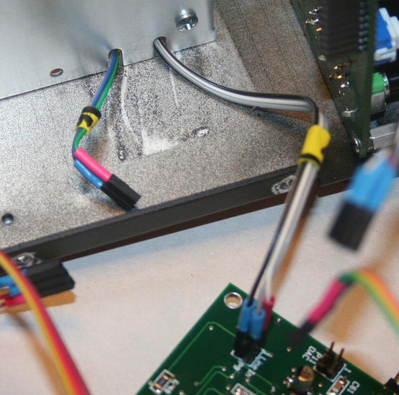
10 Page 10 of 13 STEP 12: Connect the remaining cables to the SR-Base assembly. Insert the RXAMP into position on the SR-Base board and connect its control Cable #2 to the RXAMP connector P1, carefully noting the proper location of pin 1 on the connector. (This connector carries both 5V and ground, so if improperly inserted, some damage can occur.) Connect Cable #4 (I2C) to P6 on the SR-Base board at the top-middle location. Pin 1 is oriented to the right. Connect Cable #5 to P5 on the SR-Base board at the top-right location. Pin 1 is oriented to the left. Connect the longer single-wired PTT connector down to P4 on the SR-Base board at the lower left location. Connect Cable #3 to P7 on the SR-base board at the top-left location. Pin 1 is oriented to the left. Tuck the cables going over the top edge of the sub-chassis into a convenient access slot, such that when the top cover is placed on the chassis, the wires will not be pinched.
 NOTE: If you reached this step and have not yet attached the nylon standoffs during the DSP board assembly phase, you may need to remove the DSP board connector from its mating jack in the Controls")
 need to be attached to the bottom side of the DSP board at the")
11 Page 11 of 13 STEP 13: Attach 1/4" nylon standoffs to the top and bottom corners of the DSP board (If not already done earlier during DSP board assembly.) NOTE: If you reached this step and have not yet attached the nylon standoffs during the DSP board assembly phase, you may need to remove the DSP board connector from its mating jack in the Controls board in order to do this step. To handle the natural outward bending of the DSP board mentioned before, two #4 threaded nylon standoffs (from the DSP board kit) need to be attached to the bottom side of the DSP board at the upper-rear and lower-rear corners, using the remaining #4-40 screw. These will gently hold the DSP board away from the chassis mounting lip and the inside of the top cover when in place. (There is enough force in the DSP board mounting such that there will be no vibrating or undue stress applied to the board.) STEP 14: Attach the top cover, using the #4-40 black flat head screws remaining from the Man Enclosure assembly step

12 Page 12 of 13 STEP 15: Attach the main tuning knob Using the nice black anodized aluminum knob remaining from the Controls board kitting, position the knob over the shaft of the rotary encoder on the front panel and tighten down the set screw to hold it in place. Ensure that the knob is positioned at least 3/16" above the front panel such that the encoder's pushbutton has sufficient travel to reliably engage. Some minimal "knob wobble" may be experienced while turning the encoder, and this is normal even with the better quality encoder and aluminum knob that we chose for the Cube. This wobble may be reduced, if desired, by carefully placing shims between the knob and shaft. Some experimentation may be necessary to achieved desired results.
13 Page 13 of 13 Congratulations, the SDR Cube is completely assembled! Next... move on to the RF Functional Test section! Back to Construction Home Copyright 2010 Midnight Design Solutions, LLC. All Rights Reserved. Page last updated: Jan 9, 2011
SDR Cube Transceiver Online Assembly Guide
 SDR Cube Transceiver Online Assembly Guide Detailed construction notes for building and testing each of the SDR Cube kit modules Home Bill of Materials I/O Board Controls Board DSP Board Softrock SR-Base
Section 5: Installing Parts from the Controls and Connectors Bag
 Section 5: Installing Parts from the Controls and Connectors Bag 1) Install Pinheaders & Sockets Using the Component Layout Diagram in Appendix A as a guide, install all pinheaders and strip sockets on
Quicksilver 606 TR-606 CPU Upgrade
 Quicksilver 606 TR-606 CPU Upgrade D650C 128 Installation Guide Social Entropy Electronic Music Instruments TABLE OF CONTENTS WARNINGS... 1 OVERVIEW... 2 WHAT'S IN THE BOX... 3 OPENING THE TR-606 CASE...
Parts List: Part # Tools List: Instructions:
 Parts List: Part # 1 pair of Dayton Audio B652s 300-652 1 Dayton Audio DTA-2 amplifier 300-385 1 MP3 module 320-350 1 7805 +5 VDC voltage regulator 7805 1 12 VDC 2A power supply 129-077 1 2.1 mm panel
SDR Cube Transceiver Online Assembly Guide
 Assembling the SDR Cube Transceiver SDR Cube Transceiver Online Assembly Guide Select links below for detailed construction notes for building & testing the SDR Cube kit modules Home Bill of Materials
REMOTE HEAD ADAPTER INSTALLATION GUIDE
 REMOTE HEAD ADAPTER INSTALLATION GUIDE The Remote Head adapter is a valuable accessory for the Uniden BC-780, 785 and 796 scanners. It allows the scanner's control panel to be removed from the radio and
G12/G12x USER S MANUAL
 G12/G12x USER S MANUAL TABLE OF CONTENTS SECTION 1 SLIDE CONFIGURATION SECTION 2 SLIDE CONFIGURATION ACCESSORIES SECTION 3 TABLETOP CONFIGURATION SECTION 4 TABLETOP CONFIGURATION ACCESSORIES SECTION 5
OnePlus 5 Screen and Digitizer Assembly Replacement
 OnePlus 5 Screen and Digitizer Assembly Replacement Follow this guide to replace the screen and digitizer for the OnePlus 5. This replaces the screen as well as the frame it is attached to. Written By:
Z-Truck (Vertical Moving) Z-truck Flag. Y-Truck (Horizontal Moving) FIGURE 1: VIEW OF THE Z-TRUCK. Flexshaft Assembly
 Z-truck Flag. Y-Truck (Horizontal Moving) FIGURE 1: VIEW OF THE Z-TRUCK. Flexshaft Assembly") Replacing the LCD Cable To remove and replace the LCD Cable you will need the following tools: #2 Phillips screwdriver (magnetic tip preferred) Socket wrench with 10mm socket Removing the Side Panel 1.
Replacing the LCD Cable To remove and replace the LCD Cable you will need the following tools: #2 Phillips screwdriver (magnetic tip preferred) Socket wrench with 10mm socket Removing the Side Panel 1.
Elecraft K3 KPA3 Power Connector Replacement Revision B, June 30, 2017 Copyright 2017, Elecraft, Inc. All Rights Reserved
 Introduction Elecraft K3 KPA3 Power Connector Replacement Revision B, June 30, 2017 Copyright 2017, Elecraft, Inc. All Rights Reserved The connectors furnishing high current to the KPA3 module have failed
VeNICE 2002 VeNICE 2002-PRO Range Rover L Bluetooth Audio Input Module
 VeNICE 2002 VeNICE 2002-PRO Range Rover L322 2002-2005 Bluetooth Audio Input Module Thank you and congratulations for the purchase of the L322 VeNICE Bluetooth module! We are urged to remind you that any
Q2 XBee Handheld Controller Assembly Guide
 Q2 XBee Handheld Controller Assembly Guide Copyright Quantum Robotics Inc. Q2 Controller V1.0 1 Parts List: The kit comes with 14 individual bags. 1. Case Top and Bottom 2. Case Screw Package containing:
RC Tractor Guy Controller V2.1 Assembly Guide
 RC Tractor Guy Controller V. Assembly Guide Features 0 Push button inputs Dual axis thumb sticks with built-in push button Rotary encoders with built-in push button MCU Socket to suit Meduino Mega 560
CHARLY NO-LIMIT INSTALLATION
 CHARLY NO-LIMIT INSTALLATION Start by pulling the chin strap out of the ear pad. Then fold the ear pad back to the outside of the helmet. Use a piece of masking tape or painter s tape to hold these parts
Pandora Assembly Instructions With Diamond Systems PC/104 CPUs (Athena, Elektra and Prometheus) November, 2006
 November, 2006") Pandora Assembly Instructions With Diamond Systems PC/104 CPUs (Athena, Elektra and Prometheus) November, 2006 Diamond Systems Corp. (650) 810-2500 www.diamondsystems.com This document describes how to
Pandora Assembly Instructions With Diamond Systems PC/104 CPUs (Athena, Elektra and Prometheus) November, 2006 Diamond Systems Corp. (650) 810-2500 www.diamondsystems.com This document describes how to
IQ32 Upgrade Kit Assembly Instructions
 IQ32 Upgrade Kit Assembly Instructions Jim Veatch WA2EUJ September 17, 2018 TABLE OF CONTENTS 1. INTRODUCTION... 3 2. IQ-32 UPGRADE KIT INVENTORY... 4 3. PREPARING THE RS-HFIQ AND SIDE PANELS... 6 4. CONNECTING
StationPro II Network Manual rev. 06/27/2010
 StationPro II Network Manual rev. 06/27/2010 The StationPro system is designed so that two or three of the SP- II units can be networked together, allowing a total of nine radios and nine amplifiers to
Alesis MMT8 16x Memory Expansion Modification (Black model MMT8 s) Equipment. Components required. Other bits:
 Equipment. Components required. Other bits:") Alesis MMT8 16x Memory Expansion Modification (Black model MMT8 s) by Graham Meredith, 006 Revised 15 th January 009 gmeredith1@yahoo.com.au This modification expands the memory of the Alesis MMT8 to 16x
Alesis MMT8 16x Memory Expansion Modification (Black model MMT8 s) by Graham Meredith, 006 Revised 15 th January 009 gmeredith1@yahoo.com.au This modification expands the memory of the Alesis MMT8 to 16x
ASSET LGA1366 Top-side Probe
 ASSET LGA1366 Top-side Probe (Manual version 1.1) For gaining test access to the debug port of Intel processors that are designed for use in LGA1366 Sockets (Socket B). These include the Intel Core i7
Assembly of the TACOS WAT-910BD Housing v2
 1) Circuit Diagram 2) Assembly of PCB a)tools Required. Only simple hand tools are necessary to complete the assembly of the PCB. - Soldering Iron and solder - Needle nose pliers - Wire clippers/trimmers
P160 User s Manual Manuel de l utilisateur Anwenderhandbuch Manuale per l operatore Manual del usuario
 P10 User s Manual Manuel de l utilisateur Anwenderhandbuch Manuale per l operatore Manual del usuario At Antec, we continually refine and improve our products to ensure the highest quality. So it's possible
Populating and Installing Synthex Rev 2/3 EPROM adapter board. R Grieb 5/13/2018
 Populating and Installing Synthex Rev 2/3 EPROM adapter board. R Grieb 5/13/2018 Please read these instructions before purchasing or installing the EPROM adapter, to make sure you are comfortable performing
Microsystems. SCI-6 Sound Card Interface Kit Version 1.09 January 2015
 UM Unified Microsystems SCI-6 Sound Card Interface Kit Version 1.09 January 2015 The SCI-6 interface was designed to be a low cost, high quality interface between your PC s sound card and radio transceiver.
[Note: Power adapter is not included in the kits. Users need to prepare a 9 12 V ( >300mA capacity ) DC power supply]
![[Note: Power adapter is not included in the kits. Users need to prepare a 9 12 V ( >300mA capacity ) DC power supply]](/thumbs/76/74094055.jpg "[Note: Power adapter is not included in the kits. Users need to prepare a 9 12 V ( >300mA capacity ) DC power supply]") 062 LCD Oscilloscope Assembly Notes Applicable Models: 06203KP, 06204KP DN062-18v02 Important Notes 1. Some components shown in the schematic and PCB layout are for options or adjustments. They do not
062 LCD Oscilloscope Assembly Notes Applicable Models: 06203KP, 06204KP DN062-18v02 Important Notes 1. Some components shown in the schematic and PCB layout are for options or adjustments. They do not
Elecraft W1 SWR/Wattmeter Enclosure by W8FGU
 Elecraft W1 SWR/Wattmeter Enclosure by W8FGU The W1 enclosure is made of Lexan, a polycarbonate, which is very strong. It also has a UV blocking coating on one side and was assembled carefully with this
TABLE OF CONTENTS SECTION 1 TABLETOP CONFIGURATION SECTION 2 TABLETOP CONFIGURATION ACCESSORIES SECTION 3 SLIDE CONFIGURATION
 S6 USER S MANUAL TABLE OF CONTENTS SECTION 1 TABLETOP CONFIGURATION SECTION 2 TABLETOP CONFIGURATION ACCESSORIES SECTION 3 SLIDE CONFIGURATION SECTION 4 SLIDE CONFIGURATION ACCESSORIES SECTION 5 RACK MOUNT
imac Intel 27" EMC 2639 Hard Drive
 imac Intel 27" EMC 2639 Hard Drive Replacement Replace the Hard Drive in your imac Intel 27" EMC 2639. Written By: Walter Galan ifixit CC BY-NC-SA www.ifixit.com Page 1 of 26 INTRODUCTION Replacing the
How To Install: C4000 EMV Upgrade Kit
 How To Install: C4000 EMV Upgrade Kit IMPORTANT: Before proceeding with installation please verify you have the current card reader bezel in the kit. Correct bezel will have a small eject pin hole below
Replacement Instructions. Backplane PCA for the HP Router 650
 Replacement Instructions Backplane PCA for the HP Router 650 Copyright Hewlett-Packard Company 1994. All rights reserved. Publication Number 5962-8369 Edition 1, August 1994 Printed in USA This guide provides
Insert the male, 90 angled, 2x10 connectors into the corresponding 2x10 sockets and put them in place, flat under the PCB. Solder.
 MC624 Assembly guide Safety warning The kits are main powered and use potentially lethal voltages. Under no circumstance should someone undertake the realisation of a kit unless he has full knowledge about
Installing the Server into a Rack
 Installing the Server into a Rack Note These instructions apply to multiple models; illustrations may vary slightly. Rack Mount Kit Inventory Before installing the chassis on a standard 4-post rack, make
Prisma II Chassis 56-Port Upgrade Technical Bulletin
 Prisma II Chassis 56-Port Upgrade Technical Bulletin Overview Audience Introduction This technical bulletin applies to all cable system operators and technicians who use the Prisma II Chassis configured
Written By: Walter Galan
 Replace a cracked screen on your iphone 4S. Written By: Walter Galan ifixit CC BY-NC-SA www.ifixit.com Page 1 of 32 INTRODUCTION Use this guide to replace the screen on your iphone 4S. After successfully
ROTOPOD PERISCOPE LIGHTING KIT
 ROTOPOD PERISCOPE LIGHTING KIT (for ULTIMATE Periscopes) 14-MAR-2013_rev 2.0 I designed the Periscope Lighting Kit to be as flexible as possible. Every LED is individually controllable. I have provided
Replacing the Power Supply
 APPENDIX B This appendix includes information on how to replace the power supply for the Cisco AS550XM universal gateway and contains the following sections: Safety Recommendations, page B-1 Required Tools
PARTS LIST 1 x PC Board 36 x 5mm Red LED 36 x 12mm LED Standoff 36 x NPN Transistor 36 x 10kΩ Resistor OTHER PARTS YOU MAY NEED
 PARTS LIST 1 x PC Board 36 x 5mm Red LED 36 x 12mm LED Standoff 36 x NPN Transistor 36 x 150Ω Resistor 36 x 10kΩ Resistor 17 x Mini Toggle on-off 8 x Mini Toggle (on)-off-(on) 1 x 470Ω Resistor 1 x 47µF
Use flat head screws for the out side of chassis and pan head screw for inside of chassis.
 These are instructions are guidelines in building a Storage Pod. 2-a Use flat head screws for the out side of chassis and pan head screw for inside of chassis. 1. Take the main chassis and check the chassis
Packaging the Elecraft XG2 Receiver Test Oscillator and 2T -gen 2-Tone Test Oscillator Phil Salas AD5X
 Packaging the Elecraft XG2 Receiver Test Oscillator and 2T -gen 2-Tone Test Oscillator Phil Salas AD5X My two recent test equipment additions are the Elecraft XG2 Receiver Test Oscillator, and the Elecraft
Alesis MMT8 16x Memory Expansion Modification (all grey model MMT8 s)
") Alesis MMT8 16x Memory Expansion Modification (all grey model MMT8 s) by Graham Meredith, 2006 Revised 13 th January 2009 gmeredith1@yahoo.com.au This modification expands the memory of the Alesis MMT8
Alesis MMT8 16x Memory Expansion Modification (all grey model MMT8 s) by Graham Meredith, 2006 Revised 13 th January 2009 gmeredith1@yahoo.com.au This modification expands the memory of the Alesis MMT8
SNA KIT Assembly Guide
 SNA KIT Assembly Guide Ver 0.8 April 2015 Note: Many references still exist to the SNA Kit s predecessor (NAT Kit). Also, the parts and additional steps used to make the NAT an SNA have not yet been shown
PoE/FPR Kit for Auto-Sync Time Clock. The Auto-Sync Time Clock is a validated time system with a Web interface and auto discovery.
 ASTCPOEK PoE/FPR Kit for Auto-Sync Time Clock The Auto-Sync Time Clock is a validated time system with a Web interface and auto discovery. The ASTCPOEK Kit provides Power over Ethernet with Full Power
imac Intel 21.5" Retina 4K Display (2017) RAM
 RAM") imac Intel 21.5" Retina 4K Display (2017) RAM Replacement Learn how to replace or upgrade the RAM in your 2017 Retina 4K imac. Written By: Evan Noronha ifixit CC BY-NC-SA www.ifixit.com Page 1 of 38 INTRODUCTION
imac Intel 21.5" Retina 4K Display (2017) RAM Replacement Learn how to replace or upgrade the RAM in your 2017 Retina 4K imac. Written By: Evan Noronha ifixit CC BY-NC-SA www.ifixit.com Page 1 of 38 INTRODUCTION
Gateway Profile 4 service guide
 Gateway Profile 4 service guide Customizing Troubleshooting Contents Replacing Components in Your Gateway Profile 4.................. 1 About this guide.....................................................
FreeNAS Mini and Mini XL Network Upgrade Kit
 FreeNAS Mini and Mini XL Network Upgrade Kit June 2017 Edition For more information about the FreeNAS Mini product line and a digital download of this guide, visit www.ixsystems.com/freenas-mini/ Table
HDMI Upgrade for the Showcase DVD
 THE LEADER IN AUDIO ENGINEERING for the Showcase DVD INSTALLATION AND SETUP GUIDE Getting Started THERE ARE NO USER- SERVICEABLE PARTS INSIDE ANY KRELL PRODUCT. Krell authorizes this HDMI upgrade to the
9109 FXS Analog Voice Application Module (APM) Installation Instructions. Product Documentation on the World Wide Web
 Installation Instructions. Product Documentation on the World Wide Web") TM 9109 FXS Analog Voice Application Module (APM) Installation Instructions Document Number 9109-A2-GN12-40 May 1999 Product Documentation on the World Wide Web We provide complete product documentation
TM 9109 FXS Analog Voice Application Module (APM) Installation Instructions Document Number 9109-A2-GN12-40 May 1999 Product Documentation on the World Wide Web We provide complete product documentation
iphone 3G Headphone Jack Replacement Replace a broken audio port in an iphone 3G. Written By: irobot ifixit CC BY-NC-SA
 iphone 3G Headphone Jack Replacement Replace a broken audio port in an iphone 3G. Written By: irobot ifixit CC BY-NC-SA www.ifixit.com Page 1 of 18 INTRODUCTION No audio? Replace the headphone jack! TOOLS:
Removing and Replacing Parts
 Removing and Replacing Parts Preparing to Work Inside the Computer Recommended Tools Screw Identification System Components Hard Drive Fixed Optical Drive Media Bay Devices Memory Modules Mini PCI Card
ipod Classic Headphone Jack & Hold Switch Replacement
 ipod Classic Headphone Jack & Hold Switch Replacement Replace Headphone Jack & Hold Switch to fix no audio and/or no unlock Written By: irobot ifixit CC BY-NC-SA www.ifixit.com Page 1 of 22 INTRODUCTION
the TS-520 Noise Blanker board to and making wiring changes to your SB-303 receiver!!!!
 The Kenwood TS-520 s Noise Blanker board, ID# X54-1080-10, can be installed in a Heathkit SB-303 receiver quite easily. The Noise Blanker board operates directly off of the SB-303 s 15VDC supply. Therefore,
Chapter 4 Replacement Procedures
 Chapter 4 Replacement Procedures 4 4-ii Satellite P30 Series Maintenance Manual Chapter 4 Contents 4.1 General... 4-1 4.2 Battery... 4-7 4.3 PC Card... 4-8 4.4 HDD... 4-10 4.5 Optical Drive Module... 4-12
LED Lighting Kit For Elara NanoEdge Fixed Frame. Installation Guide. Attention: Read this guide before assembling your screen.
 LED Lighting Kit For Elara NanoEdge Fixed Frame Installation Guide Attention: Read this guide before assembling your screen. INTRODUCTION GETTING STARTED WARNING - Sharp Edges This product may contain
Page. Foreword. We sincerely hope that you enjoy using our product! P2 - INDEX
 Page 2... Index, Foreword 3... Product Overview 4... Preparation for Assembly 5-6... Installing the Motherboard 7... Installing the Passive CPU Cooler 8... Fitting the HDD/ODD 9... PCB Wiring Diagram 10...
Phase Loss Protection Upgrade. Phase Loss Protection Upgrade. In this bulletin:
 Phase Loss Protection Upgrade In this bulletin: Introduction... 2 Purpose... 2 General... 2 Applicability... 2 HD3070 Phase Loss Protection Upgrade Kit Parts... 2 Preparation... 4 Install the Phase Loss
ZeroView. Raspberry Pi Camera Module Suction Mount User Guide and Information. Product Page: ThePiHut.com/zeroview
 ZeroView Raspberry Pi Camera Module Suction Mount User Guide and Information Product Page: ThePiHut.com/zeroview 2 Guide Contents Introduction 3 Design Features 4 Kit Contents 5 Assembly 6 Enabling the
CIB 3047 (14B) 10-Button Voice Terminal Fixed Desk Stand and Wall Mount (32007)
 10-Button Voice Terminal Fixed Desk Stand and Wall Mount (32007)") CIB 3047 (14B) 10-Button Voice Terminal Fixed Desk Stand and Wall Mount (32007) CIB 3047 Comcode 845-659-325 Issue 1 CIB 3047 (14B) 10-Button Voice Terminal Fixed Desk Stand and Wall Mount (32007) This
CIB 3047 (14B) 10-Button Voice Terminal Fixed Desk Stand and Wall Mount (32007) CIB 3047 Comcode 845-659-325 Issue 1 CIB 3047 (14B) 10-Button Voice Terminal Fixed Desk Stand and Wall Mount (32007) This
Phi-panel backpack assembly and keypad options Dr. John Liu 12/16/2012
 Phi-panel backpack assembly and keypad options Dr. John Liu 12/16/2012 1. Introduction:... 3 Currently available:... 3 2. Backpack assembly... 4 3. Connecting to a keypad... 6 4. Rotary encoder keypads...
HP Photosmart c3180 Main Circuit Board Replacement
 HP Photosmart c3180 Main Circuit Board Replacement Replacing a faulty main circuit board. Written By: Jim ifixit CC BY-NC-SA www.ifixit.com Page 1 of 26 TOOLS: Spudger (1) T10 Torx Screwdriver (1) ifixit
Replacement Keyswitch Assembly
 Installation Instructions Replacement Keyswitch Assembly (Catalog No. 2711E-NKSW1) Applicable Terminals Use this replacement keyswitch with PanelView Terminals 2711-KA1, -KC1, -TA1, -TC1, -TA4, -TC4 and
NOTE: Read the instructions completely through before beginning actual installation.
 CONSOLE CONNECTOR KIT 7850 INSTALLATION INSTRUCTIONS FOR USE WITH: Various Two-channel Organs LESLIE Speaker Models 705, 705C, 720 KIT CONTENT Console Connector 138488 Switch Assembly, Cable Assembly,
Written By: Ben Eisenman
 iphone 3GS Rear Panel Replacement Replace a broken rear case on your iphone 3GS. Written By: Ben Eisenman ifixit CC BY-NC-SA www.ifixit.com Page 1 of 22 INTRODUCTION The plastic rear half of the iphone.
ipad Mini Wi-Fi Front Facing Camera Replacement
 ipad Mini Wi-Fi Front Facing Camera Replacement Replace the Front Facing Camera in your ipad Mini Wi-Fi. Written By: Andrew Optimus Goldberg ifixit CC BY-NC-SA www.ifixit.com Page 1 of 42 INTRODUCTION
Installing PRO/DGX or Pro Soloist MIDI interface. R Grieb 9/08/2017
 Installing PRO/DGX or Pro Soloist MIDI interface. R Grieb 9/08/2017 Please read these instructions before purchasing the MIDI interface, to make sure you are comfortable performing the necessary steps.
imac Intel 21.5" EMC 2389 Stand Replacement
 imac Intel 21.5" EMC 2389 Stand Replacement Replace a broken or cosmetically unappealing stand on the imac 2389 21.5 Written By: Aaron Cooke ifixit CC BY-NC-SA www.ifixit.com Page 1 of 30 INTRODUCTION
CONTENTS. 1. Motherboard installation Install 5¼ and 3½ drives Install PCI components Case fan setup...5
 USER S MANUAL CONTENTS 1. Motherboard installation...1 2. Install 5¼ and 3½ drives...3 3. Install PCI components...4 4. Case fan setup...5 5. Connect case leads to motherboard...6 6. Identify the power
Sonnet AV/HPV Card Video Adapter Kit
 Installation Instructions for Power Macintosh 7100 and 8100 Adapter Kit Inventory Before installing the AV/HPV Card Video Adapter, you will require the following items (Figure 1): Included with adapter
TECHKNOW, INC. Kiosk Order Confirmation System INSTALLATION MANUAL. Revision Date: July 11, 2012 Part # Version 3.2
 document Page 1 of 18 TECHKNOW, INC Kiosk Order Confirmation System INSTALLATION MANUAL Revision Date: July 11, 2012 Part # Version 3.2 Techknow, Inc. 393 Mayfield Road Duncan, SC 29334 www.gotechknow.com
Star Trac Fitness E-ST 5090 Stepper. Install Guide
 Star Trac Fitness E-ST 5090 Stepper Install Guide STAR TRAC E-ST STEPPER Install Guide E-ST 5090 E Series Stepper ASSEMBLY AND SETUP The following parts are included with the base STAR TRAC E-ST STEPPER:
TIME WIZARD MULTI CLOCK DIVIDER BUILDING GUIDE
 TIME WIZARD MULTI CLOCK DIVIDER BUILDING GUIDE Table of Contents 0. Components List + Tools 0. PCB Sides 03. PCB Assembly 04_. Diode N448 04_. Laying Resistors 04_3. Capacitors 04_4. Quartz 04_5. 78L05
Part 2: Building the Controller Board
 v3.01, June 2018 1 Part 2: Building the Controller Board Congratulations for making it this far! The controller board uses smaller components than the wing boards, which believe it or not, means that everything
Three Hundred. User s Manual Manuel de l utilisateur Anwenderhandbuch Manuale per l operatore Manual del usuario
 Three Hundred User s Manual Manuel de l utilisateur Anwenderhandbuch Manuale per l operatore Manual del usuario At Antec, we continually refine and improve our products to ensure the highest quality. As
Installation Instructions
 Installation Instructions Ecast EQ to AMI hardware conversion KIT #26683701 This kit is for use in Ecast EQ jukeboxes. Tools Required #2 Phillips screw driver, #1 Phillips screw driver, Small flat blade
Reflowing Xbox 360 Motherboard
 Reflowing Xbox 360 Motherboard Reflow the solder on your Xbox 360's motherboard. Written By: Andrew Bookholt ifixit CC BY-NC-SA www.ifixit.com Page 1 of 31 INTRODUCTION Use this guide to reflow the solder
CP5176 Assembly guide. Soldering. CP5176 Assembly guide Main PCB PCB split. Document revision 2.1 Last modification : 12/11/17
 CP5176 Assembly guide Safety warning The kits are main powered and use potentially lethal voltages. Under no circumstance should someone undertake the realisation of a kit unless he has full knowledge
Series 3700 Screw Terminal Assemblies Installation Instructions
 Keithley Instruments, Inc. 28775 Aurora Road Cleveland, Ohio 44139 1-888-KEITHLEY www.keithley.com Series 3700 Screw Terminal Assemblies Installation Instructions Introduction This document contains handling
CINTENNA ANTENNA REPAIR GUIDE
 The Cintenna is a great tool when looking to transmit WIRELESS DMX data over obstacles or hard to reach places. Wireless DMX can have its issues when not having a good line of sight between the transmitter
EMC 10/4 "CE" Mechanical Upgrade Procedure
 EMC 10/4 "CE" Mechanical Upgrade Procedure Kit Part Number: 009663-01 This procedure upgrades a non-ce compliant machine to the mechanical requirements of a CE compliant machine. Properly upgraded machines
PowerBook G4 Aluminum 12" GHz Display Data Cable Replacement
 PowerBook G4 Aluminum 12" 1-1.5 GHz Display Data Cable Replacement Written By: Matthew Newsom ifixit CC BY-NC-SA www.ifixit.com Page 1 of 47 INTRODUCTION Replace a damaged display data cable to restore
imac Intel 20" EMC 2133 and 2210 Optical Drive Data Cable Replacement
 imac Intel 20" EMC 2133 and 2210 Optical Drive Data Cable Replacement Scritto Da: Walter Galan ifixit CC BY-NC-SA it.ifixit.com Pagina 1 di 24 INTRODUZIONE Replace a broken optical drive data cable to
How to add a Second Drive to a Mac mini (2012) using the OWC Data Doubler SSD/2.5 Installation Kit
 using the OWC Data Doubler SSD/2.5 Installation Kit") Instructional Video Series How to add a Second Drive to a Mac mini (2012) using the OWC Data Doubler SSD/2.5 Installation Kit Skill Level: Challenging Time to Complete: Approximately 45 Minutes Required
Instructional Video Series How to add a Second Drive to a Mac mini (2012) using the OWC Data Doubler SSD/2.5 Installation Kit Skill Level: Challenging Time to Complete: Approximately 45 Minutes Required
Pan-Tilt-Zoom Security Camera
 Security Made Smarter Pan-Tilt-Zoom Security Camera For use with Swann Pro-Series 080p DVRs EN INSTRUCTION MANUAL M080VERE Swann 07 7 5 8 6 4 VIDEO INPUT 4 INPUT OUTPUT VGA RS485 LAN V Step One - Introduction
ABM International, Inc. Lightning Stitch Checklist 9/13/2013
 ABM International, Inc. Lightning Stitch Checklist 9/13/2013 1) Piggy backed board assembly (1) Piggy back board assembly tested? Yes No 24v passed XB passed XA passed YB passed YA passed SAFE passed S/S
PowerBook G4 Aluminum 12" GHz Left Clutch Hinge Replacement
 PowerBook G4 Aluminum 12" 1-1.5 GHz Left Clutch Hinge Replacement Written By: Matthew Newsom ifixit CC BY-NC-SA www.ifixit.com Page 1 of 50 INTRODUCTION Replace a broken clutch hinge to make your display
INSTALLATION INSTRUCTIONS
 CONSOLE CONNECTOR KIT 7830 FOR USE WITH: LESLIE Speaker Model 130 Various single and double channel organs INSTALLATION INSTRUCTIONS KIT CONTENT Console Connector 137283 Switch Assembly, Cable Assembly,
TDM To MiniMech conversion ProceDure
 TDM To MiniMech conversion ProceDure (Model 9100 ATM) TDN 07102-00079 Apr 1 2009 CorporATe HeAdquArTers: 522 E. Railroad Street Long Beach, MS 39560 PHONE: (228) 868-1317 FAX: (228) 868-0437 COPYRIGHT
1. Carefully unpack the um260 s shipping carton and check the contents for damage.
 um260 Installation Manual um260 Installation Chapter 4 um260 MICRO MONITOR INSTALLATION This section of the um260 Micro Monitor Installation Manual describes the requirements and procedures for installing
Replacing the PanelMate Power Pro 1785 Series, PanelMate epro 7585x-8 and 7685x-8 Series Backlight Assembly
 Replacing the PanelMate Power Pro 1785 Series, PanelMate epro 7585x-8 and 7685x-8 Series Assembly Introduction The Replacement Kit provides a replacement backlight for the PanelMate Power Pro 1785 Series,
GPIB-232CT-A IBCL EPROM Installation Guide
 NATIONAL INSTRUMENTS The Software is the Instrument Installation Guide GPIB-232CT-A IBCL EPROM Installation Guide This guide describes how to replace the factory-installed EPROM that comes with your GPIB-232CT-A.
imac Intel 27" EMC 2429 SSD Dual Drive
 imac Intel 27" EMC 2429 SSD Dual Drive Installation Install the dual hard drive kit in an imac Intel 27" EMC 2429. Written By: Dozuki System 2017 guides.crucial.com Page 1 of 22 INTRODUCTION This guide
OpenSprinkler v2.2u Build Instructions
 OpenSprinkler v2.2u Build Instructions (Note: all images below are 'clickable', in order for you to see the full-resolution details. ) Part 0: Parts Check Part 1: Soldering Part 2: Testing Part 3: Enclosure
EQ573 Assembly guide. EQ573 Assembly guide Main board 1. Diodes. 2. Resistors (1) 3. Test pins. 4. Ceramic capacitors.
 3. Test pins. 4. Ceramic capacitors.") EQ573 Assembly guide Safety warning The kits are main powered and use potentially lethal voltages. Under no circumstance should someone undertake the realisation of a kit unless he has full knowledge about
EQ573 Assembly guide Safety warning The kits are main powered and use potentially lethal voltages. Under no circumstance should someone undertake the realisation of a kit unless he has full knowledge about
Lightning Stitch Assembly
 ABM International, Inc. 1 1.0: Parts List Lightning stitch motor and drive assembly (Qty. 1) Lightning stitch piggy backed controller board assembly (Qty. 1) Touchscreen (Qty. 1) 2 9-pin Serial cable (Qty.
Figure 4-29 Removing the CPU compartment cover
 4 Replacement Procedures 4.9 CPU 4 4.9 CPU Removing the CPU To remove the CPU, follow the steps below. 1. Turn the computer upside down and remove two M2.5 4 security screws securing the CPU compartment
PS/IO Circuit Board Retrofit
 S&C 6800 Series Automatic Switch Controls PS/IO Circuit Board Retrofit Table of Contents Section Page Introduction Qualified Persons.... 2 Read this Instruction Sheet.... 2 Retain this Instruction Sheet....
Installation Instruction VCPRGBGM05 - rev1.5 RGB Interface Harness modification Navigation Radio
 Introduction The following instruction procedure is for the RGB interface to a GM 05 Nav Radio as part of the Webasto Product NAVCam Back-up Camera (VCP-0000220). In addition, an installer will need to
Installation Instructions. Ecast Mojo B75B Motherboard Upgrade Kit Kit #
 Installation Instructions Ecast Mojo B75B Motherboard Upgrade Kit Kit #26684501 This kit contains the parts and instruction to install the B75B Motherboard into your Ecast Mojo jukebox. Tools Required
Page
 Page 2... 3... 4... 5-6... 7-8... 9... 10... 11-12... 13... 14... 15... Index, Foreword Product Overview Preparation for Assembly Installing the Motherboard Installing the Passive CPU Cooler Installing
Replacing the RAID Battery Backup Unit Assembly on Series 3 FireSIGHT 3500 Defense Centers, Version 5.x
 Replacing the RAID Battery Backup Unit Assembly on Series 3 FireSIGHT 3500 Defense Centers, Version 5.x Last Updated: December 4, 2014 Use these instructions to replace the RAID battery backup unit (BBU)
To connect the AC adapter:
 Replacing the AC Adapter Replacing the AC Adapter 3 Plug the power cord into a wall outlet. The power indicator turns on. To connect the AC adapter: Connect the power cord to the AC adapter. Power indicator
imac Intel 21.5" EMC 2389 SSD Dual Drive
 imac Intel 21.5" EMC 2389 SSD Dual Drive Installation Use this guide to install a second SSD in place of the optical drive. Written By: Dozuki System 2017 guides.crucial.com Page 1 of 17 INTRODUCTION There