Contents SMARTZONE G5 USER MANUAL
|
|
|
- Oswald Bryan
- 5 years ago
- Views:
Transcription

1 G5 PDU User Manual
2 1 Contents Figures... 4 Section 1 System Overview... 6 Intelligent Network Controller... 6 Connecting the PDU to a LAN Ethernet Port... 6 Connecting the PDU to a Computer Serial Port... 7 Setup Serial Communication... 8 Section 2 Web Graphical User Interface (GUI) Configuration Internet Protocol (IP) Address Web Configuration Supported Web Browsers Logging in to the Web Interface Introduction to the Web GUI Menu Dropdowns Introduction to the Dashboard Section 3 Simple Network Management Protocol (SNMP) SNMP Management Configuration Configuring Users for SNMP v3 Communications Section 4 Command Line Interface (CLI) Configuration Connecting through CLI connection Supported Commands Connecting to the CLI through the serial interface Section 5 Local Display OLED Display Menu Mode OLED Menu Structure Main Menu Selections... 31
3 2 Setup Menu Sensors Menu Section 6 User Access Access Types Setting up the system for Radius Authentication Configuring the system with LDAP Server Settings Section 7 Daisy Chain Configuration Daisy-Chain Overview Daisy-Chain Setup RNA (Redundant Network Access) Functionality RNA Setup Section 8 Web GUI configuration G5 ipdu Outlet Power Sequence Setup Section 9 Connecting and Configuring Optional Hardware Accessory Hardware Overview Configuring Environmental Sensors Warranty and Regulatory Information Warranty Information Regulatory Information Support and Other Resources Accessing Panduit Support Acronyms and Abbreviations Documentation Feedback Appendix A: CLI Commands Appendix B: Firmware Update Procedure USB Method Web Interface Method FTPs Method Bootloader Mode... 83
4 3 Firmware Recovery with Bootloader Mode Appendix C: System Recovery Upgrade Configuration with Bootloader Mode Appendix D: PDU Alarms Trap Codes assigned to Alarms List Appendix E: Horizontal Intelligent Network Controller Replacement Appendix F: Vertical Intelligent Network Controller Replacement... 95
5 4 Figures Figure 1: Ethernet Port for Network Connection... 7 Figure 2: Locate Reset Button... 8 Figure 3: Port Setup Settings... 9 Figure 4: Login Page Figure 5: Landing Page Figure 6: Power Summary Page Figure 7: Outlet Monitoring Page Figure 8: Environmental Page Figure 9: Security Page Figure 10: SNMP Management Figure 11: SNMP General Figure 12: SNMP Port Figure 13: Setup SNMP Port and Trap Port Figure 14: Define SNMP V1/V2c User Figure 15: Edit V1/2c Manager Figure 16: SNMP V3 Manager Figure 17: SNMP V3 Edit Figure 18: Connect the RJ-45 end of the cable to the Serial+RS485-1 connector Figure 19: Serial Cable Pinout Figure 20: the OLED Display Orientation Figure 21: OLED Menu Structure Figure 22: Main Menu Selections Figure 23: Setup Menu Figure 24: Network Submenu Figure 25: Device Submenu Figure 26: Screen Submenu Figure 27: Language Submenu Figure 28: USB Submenu Figure 29: Units Submenu Figure 30: Alarms Menu Figure 31: Power Menu Figure 32: Device Submenu Figure 33: Phase Submenu Figure 34: Breaker Submenu Figure 35: Outlet Submenu Figure 36: Sensors... 44
6 5 Figure 37: Changing Your Password Figure 38: After Login Figure 39: Change User Password Figure 40: Change Password Figure 41: User Settings Figure 42: Radius Configuration Figure 43: LDAP Configuration Figure 44: Enable Role Privileges Figure 45: Test LDAP Configuration Figure 46: How to Connect Cables for Daisy Chain Figure 47:Control & Manage PDU Figure 48: Outlet Control Enabled Figure 49: Edit Outlets Figure 50: One-Delay Time Figure 51: Saved Sequence Figure 52: Sensor Ports for vertical PDU Figure 53: Sensor Ports for Horizontal PDU Figure 54: Update Firmware Figure 55: Upload Firmware Figure 56: Unscrew Intelligent Network Controller Figure 57: Remove Intelligent Network Controller from PDU Figure 58: Inserting New Intelligent Network Controller Figure 59: Removing Top and Bottom Screw from Intelligent Network Controller Figure 60: Disconnecting and Reconnecting the Intelligent Network Controller... 96
7 6 Section 1 System Overview Intelligent Network Controller The Panduit Monitored Input, Monitored & Switched, Monitored per Outlet, and Monitored & Switched per Outlet PDUs have an integral, hot swappable Intelligent Network Controller. The Intelligent Network Controller contains the OLED interface, control buttons, the USB, Ethernet, Serial and Sensor ports, and recessed Reset Button. Reset Button Pressing the Reset Button only reboots the Intelligent Network Controller. It does not change the Energy (kwh) value and does not affect the output voltage. Using the Reset Button Press and hold the Reset Button for 8 seconds to recover from an Intelligent Network Controller communication failure. Connecting the PDU to a LAN Ethernet Port The PDU is defaulted to DHCP. If you are connected to an Ethernet with a DHCP server, the PDU automatically get an IP address and display it on the LCD screen. If there is no DHCP server, the default IP address is , but again this will be displayed on the PDU. Connecting the PDU to a LAN provides communication through an Internet or Intranet connection. You can monitor the PDU from any computer connected to the same network. The PDU is set to use DHCP (Dynamic Host Configuration Protocol) by default when delivered. If IP is successfully assigned, you will see the IP address shown on OLED display. 1. Locate the Ethernet cable. 2. Connect one end of the cable to the Ethernet port on the PDU (see Figure 1). Connect the other end of the cable to the Ethernet port on the router (or another LAN device).

8 7 Figure 1: Ethernet Port for Network Connection Connecting the PDU to a Computer Serial Port If unable to connect to network, you can change the network setting using the serial interface. To configure the network setting, perform the following steps: 1. Serial connect the PDU to a computer s serial port. Set baud rate for a terminal emulation program. 2. Using a CLI command to enable DHCP or set a static IP. 3. Verify access to the Web interface. The Ethernet LED on the PDU front panel provides communication status by color and display activity. The recessed Reset button restarts the PDU (see Figure 2 below).
.")
9 8 Figure 2: Locate Reset Button Setup Serial Communication You may configure the network settings using the command line interface (CLI) with a serial connection. Users can connect serially using the optional RJ45-DB9 cable (or make your own cable by creating a unique pinout as described below in the Serial Cable Pinout to Create Your Own Cable in Section 4). 1. Verify that the computer has a serial port. If your computer does not have a DB9 serial connector, but does have a USB connector, obtain a USB-to-DB9 Adapter to convert the USB to a DB9 serial port. 2. Using the optional RJ45-DB9 cable, connect the RJ-45 end to the port labeled Serial+RS485-1 on the front panel of your PDU model (see Figure 1). Connect the DB9 end of the cable to the computer. 3. Open the terminal emulation program (HyperTerminal or PuTTY) on the computer and select the serial port connection (such as COM1). 4. Set the communications port as follows: Bits per second: Data bits: 8
 6.")
10 9 Parity: None Stop bits: 1 Flow control: None (See Port Settings example below) Figure 3: Port Setup Settings 5. Use the default initial login indicated below. Note that the username and password are both case sensitive: Username: admin Password: (or your new password) 6. The Panduit> prompt appears after you have logged in, ready to enter the CLI command. 7. To configure network settings, enter the appropriate net command and press Enter. All commands are case sensitive. You can type? to access the commands. 8. To enable the IPv4 DHCP by default, run: net tcpip dhcp
11 10 Enter Y to confirm and the PDU s Intelligent Network Controller will reboot. 9. To set a static IPv4 configuration, run: net tcpip static x.x.x.x (ipaddress) x.x.x.x (netmask) x.x.x.x (gateway) Example: net tcpip static Enter Y to confirm and the PDU s Intelligent Network Controller will reboot.
12 11 Section 2 Web Graphical User Interface (GUI) Configuration Internet Protocol (IP) Address The PDU is by default configured Dynamic Host Configuration Protocol (DHCP). The PDU automatically obtains an IP address via a DHCP server when connected to a network. The IP address the PDU received is displayed on the OLED screen. After the PDU received the address, login to the Web interface to configure the PDU and assign a static IP address (if desired). If there is no DHCP server, the default IP address is , but again this will be displayed on the PDU. If the network does not use a DHCP server, see the CONNECTING THROUGH A SERIAL CONNECTION section to configure a static IP address. 1. Connect a standard Ethernet patch cable to the Ethernet port on the PDU. 2. Connect the other end of the Ethernet cable to the LAN. 3. Make sure the Ethernet port on the PDU shows a solid green light on the left and a flashing yellow light on the right to indicate successful connectivity to the network. 4. Use the menu buttons to look up the IP address of the device on the OLED display by selecting Setup > Network > IPv4 or IPv6 as applicable. 5. In a standard web browser, enter the PDU IP address and proceed to configure the PDU as shown in the Web Configuration section. Web Configuration Supported Web Browsers The supported Web browsers are Windows Firefox, Linux Firefox, Mozilla Firefox, Windows Internet Explorer Version 11, Microsoft Edge, and Google Chrome mobile and desktop, Apple Safari mobile and desktop. Logging in to the Web Interface Logging In Open a supported web browser and enter the IP address of the PDU. o If username and password were configured during the Network Configuration Setup: enter the username and password in the appropriate fields. Press Login or Enter.

13 12 o If username and password were NOT configured during the Network Configuration Setup, use the default username: admin and password: For security purposes, change the password upon login. Introduction to the Web GUI Login Page Figure 4: Login Page
14 13 Landing Page Figure 5: Landing Page Number Icon Description The home icon provides an overview of the PDU with access to the Dashboard, Identification, and Control & Manage. The Alarm icon provides details of the active critical alarms and active warning alarms. This icon lets you select a Language. There are seven languages available to choose from: English, Chinese, French, Italian, German, Spanish, Korean and Japanese. This icon provides the logs of the PDU which can be viewed and downloaded.
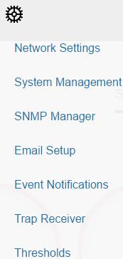
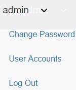
15 14 Number Icon Description The settings icon allows a user to setup the Network Settings, System Management, SNMP Manager, Setup, Event Notifications, Trap Receiver, and Thresholds. The search icon allows you to input key words and search for the related results. Information about the PDU can be found using this icon. You also can also click user guide and license to ask for help. This icon shows who is logged in (user or admin). Account passwords can be changed, and user accounts managed through this page.


16 15 Menu Dropdowns Overview Alarms Help Language Logs Settings Admin
17 16 Introduction to the Dashboard Power Summary Page Figure 6: Power Summary Page Outlet Monitoring Page Figure 7: Outlet Monitoring Page

18 17 Environmental Page Figure 8: Environmental Page Security Page Figure 9: Security Page

19 18 Section 3 Simple Network Management Protocol (SNMP) SNMP Management Configuration Setup SNMP 1. Access the Web interface and login. 2. Under SNMP Managers, select SNMP General. The SNMP General page displays. Figure 10: SNMP Management 3. The SNMP General includes SNMP Access and Version.
20 19 Figure 11: SNMP General Setup SNMP Port 1. Access the Web interface and login. 2. Under SNMP Managers, select SNMP Port. The SNMP Port page displays.

21 20 Figure 12: SNMP Port 3. Setup SNMP Port and SNMP Trap Port Figure 13: Setup SNMP Port and Trap Port
22 21 Define SNMP V1/V2c User 1. Access the Web interface and login. 2. Under SNMP Manager, select SNMP V1/V2c. 3. In the SNMP V1/V2c panel, select the SNMP V1/V2c manager to configure. Select the pencil icon in the last column. Figure 14: Define SNMP V1/V2c User 4. The Edit panel pop up displaying the configurable options. Figure 15: Edit V1/2c Manager
23 22 5. Set the following options IP Address: the IP address of the host for this SNMP V1/V2 manager. Only requests from this address will be acted upon. Note: An IP address configured to will act as a wildcard and all requests will be acted upon. Read Community: the read-only community string to allow an SNMP V1/V2c manager to read a SNMMP object. Write Community: the write-only community string to allow an SNMP V1/V2c manager to write an SNMMP object. 6. Click Enable and Save. Configuring Users for SNMP v3 Communications 1. Access the Web interface and login. 2. Under SNMP Managers, select SNMP V3. 3. In the SNMP V3 panel, select the SNMP V3 manager to configure. Select the pencil icon in the last column. Figure 16: SNMP V3 Manager 4. The Edit panel pop up displaying the configurable options.
24 23 Figure 17: SNMP V3 Edit 5. Configure the SNMP username 6. Choose a Security Level from the dropdown menu NoAuthNoPriv: No authentication and no privacy. This is the default. AuthNoPriv: Authentication and no privacy. AuthPriv: Authentication and privacy. 7. Enter a new unique password to be used for authentication 8. Select the desired authentication algorithm. MD5 SHA
25 24 9. Enter a new unique key for privacy algorithm 10. Select the desired privacy algorithm DES AES-128 AES-192 AES Click Enable and Save.
26 25 Section 4 Command Line Interface (CLI) Configuration Connecting through CLI connection The Command Line Interface (CLI) is an alternate method used to manage and control the PDU status and parameters, as well as basic admin functions. Through the CLI a user can: Reset the PDU Display PDU and network properties Configure the PDU and network settings Switch outlets on/off View user information Connecting to the CLI requires a terminal emulation program such as HyperTerminal or PuTTY Supported Commands The PDU CLI command set for managing and monitoring the PDU includes the following commands:? command: PDU help query sys command: PDU system configure and setting net command: PDU net application configure and setting usr command: PDU user operation dev command: PDU device setting pwr command: PDU power setting
![26 NOTE: Command variables are represented in command input syntax surrounded by angle braces (< >). Optional parameters are represented in command input syntax surrounded by straight brackets ([ ]).](/docs-images/87/95992597/images/27-0.jpg "For data of type array, the 'x' character as index of array in command input syntax means all indexes. You must be logged into the PDU before commands can be sent.")
27 26 NOTE: Command variables are represented in command input syntax surrounded by angle braces (< >). Optional parameters are represented in command input syntax surrounded by straight brackets ([ ]). For data of type array, the 'x' character as index of array in command input syntax means all indexes. You must be logged into the PDU before commands can be sent. See Appendix A for a list of all CLI commands. Connecting to the CLI through the serial interface Communicating through the serial port requires a specialized optional RJ45-DB9 cable or you can create your own cable as described in the Serial Cable Pinout to Create Your Own Cable section. Figure 18: Connect the RJ-45 end of the cable to the Serial+RS485-1 connector To connect the PDU to a computer: Using the optional RJ45-DB9 cable, connect the RJ-45 end to the port labeled Serial+RS485-1 on the front panel of your PDU model. Connect the DB9 end of the cable to the serial connector on the computer.
28 27 Logging in with HyperTerminal To login through HyperTerminal, set the COM settings to the following parameters: Bits per second: Data bits: 8 Parity: None Stop bits: 1 Flow control: None Serial Cable Pinout to Create Your Own Cable To make your own RJ45-to-DB9 Serial cable, the connections are wired as shown: Figure 19: Serial Cable Pinout Logging in with SSH via PuTTY 1. Ensure SSH has been enabled: On GUI, go to Device Configuration > Network Service > SSH. Select the Enable SSH Access checkbox. Select OK. 2. Open an SSH client (PuTTY). 3. Enter the IP address in the Host Name field. Select the connection type: SSH For SSH, enter 22 in the Port field. 4. Select Open. 5. Enter your Username. Press Enter. 6. Enter your password. Press Enter.
29 28 7. You are now logged into the SSH. Refer to the CLI Commands table below for available commands. NOTE: SSH connection is not available when serial connection is enabled.
. Use the buttons to change the screen display and retrieve specific performance data.")
30 29 Section 5 Local Display OLED Display The OLED provides information about the PDU and connected devices. The OLED display orientation can be changed using an OLED setting. The display can be rotated 0 and 180. The PDU has a three-button, graphical OLED panel (see Figure 4). Use the buttons to change the screen display and retrieve specific performance data. Figure 20: the OLED Display Orientation The OLED has two modes: 1. Screensaver mode: Screensaver mode cycles through a set sequence of screens that display current PDU values. Current values are refreshed every ten seconds. The user cannot select a custom sequence of screens. The screensaver displays automatically after 30 seconds of inactivity from the start-up screen, a menu, or a submenu. Values are refreshed every five seconds.
31 30 2. Menu mode (OLED main menu): The settings that display under each high level (main) menu depend on your PDU model. Menu Mode The table below summarizes how to use the control buttons on the OLED display. Button When in Menu Mode When in Screensaver Mode Menu Scroll Select from the four main menus. Scrolls down through the list of menu items. NOTE: A highlighted menu item is ready to be selected. Returns to the previous display screen before entering the screensaver mode. Returns to the previous display screen before entering the screensaver mode. Select Opens the selected menu. Returns to the previous display screen before entering the screensaver mode. LED Unit Status The LED will change colors depending on the state of the PDU. LED State Solid Green Solid Red Flashing Orange Description Normal Operation Critical or Warning Alarm No network connection
32 31 OLED Menu Structure Figure 21: OLED Menu Structure Main Menu Selections The PDU menu selection hierarchy consists of Setup, Alarms, Power, and Sensors. On the main menu, scroll down to highlight Setup. Press Select. Scroll down to select a submenu and press Select to display the submenu options. Press Menu to return to the previous menu.


33 32 Figure 22: Main Menu Selections Setup Menu The Setup menu provides user configuration options including Network, Device, Screen, Language, USB, and Units. Figure 23: Setup Menu Network Submenu The Network submenu allows you to view IP address IPv4 or IPv6. On the Setup menu, scroll down to Network. Press Select to enter the Network Submenu. Scroll down to highlight the selected option from the menu. Press Select to display the screens that display the IP address. Press Menu to return to the previous menu.
34 33 Figure 24: Network Submenu Device Submenu The Device submenu provides the SKU number, Serial number, MAC address and Firmware version. On the Setup menu, scroll down to highlight Device submenu. Press Select to enter the Device Submenu. Scroll down to the item you wish to display and press Select. Press Menu to return to the previous menu.
35 34 Figure 25: Device Submenu Screen Submenu The Screen submenu allows you to customize settings for Contrast, Rotate, and Always on. On the Setup menu, scroll down to highlight Screen. Press Select to select the submenu. Press Menu to return to the previous menu.
36 35 Figure 26: Screen Submenu Language Submenu The Language submenu allows you to select the language you need to use. On the Setup menu, scroll down to highlight Lang. Press Select to display the screens to select the submenu. After you select the values, press Select to set the values as displayed on the screen. Press Menu to return to the previous menu.
37 36 Figure 27: Language Submenu USB Submenu The USB submenu allows you to upload firmware file and download event log or data log. On the Setup menu, scroll down to highlight USB. Press Select to enter the USB Submenu. The user will be asked to verify the want to the enter the USB operation and Configuration Mode. After you select Yes, the system will reset in to the USB operation and Configuration Mode, or Boot Loader mode. Note 1: If an USB drive is not present in the USB slot the PDU will enter normal operation after the reset. Note 2: If you are in USB mode and you want to exit USB mode, you must remove the USB drive before existing USB mode. Otherwise, the PDU will reset and re-enter USB mode.
38 37 Figure 28: USB Submenu
39 38 Units Submenu The Units submenu displays the temperature units. On the Setup menu, scroll down to highlight Units. Press Select to enter the Units Submenu. After you select the values, press Select to set the values as displayed on the screen. Press Menu to return to the previous menu. Figure 29: Units Submenu Alarms Menu The Alarms menu displays active alarms for the PDU. On the Main Menu, scroll down to highlight Alarms. Press Select to display the Alarm Screen. When you finish your review, press Menu to return to the main menu.

40 39 Figure 30: Alarms Menu Power Menu The Power menu manages device, phase, breaker and outlet. On the Main Menu, scroll down to highlight Power. Press Select. Scroll down to select a submenu and press Select to display the submenu options. Press Menu to return to the previous menu. Figure 31: Power Menu
41 40 Device Submenu The Device submenu is to display current, voltage and power. On the Power menu, scroll down to highlight Device. Press Select to display the power values for the entire PDU. Press Menu to return to the previous menu. Figure 32: Device Submenu Phase Submenu The Phase submenu is to display the status of 3-Phase. On the Power menu, scroll down to highlight Phase. Press Select to display the screens to set the values for the submenu. After you select the phase, press Select to display the values for that phase on the screen. Press Menu to return to the previous menu.
42 41 Figure 33: Phase Submenu Breaker Submenu The Breaker submenu is to display power values for the breakers. Press Select to display the values of the first breaker. To go to the next breaker, Select next. Press Menu to return to the previous menu.
43 42 Figure 34: Breaker Submenu Outlet Submenu The Outlet submenu is to display voltage, current and power from outlet number 1 to number n. On the Power menu, scroll down to highlight Outlet. Press Select to display values for the first outlet. To go to the next outlet, Select next. Press Menu to return to the previous menu.
44 43 Figure 35: Outlet Submenu Sensors Menu The Sensor menu is to display temperature, humidity, door switch, fluid leak etc. On the Main Menu, scroll down to highlight Sensor. Press Select. This will display the sensor data for the first sensor. To go to the next sensor, Select next. Press Menu to return to the previous menu.
45 44 Figure 36: Sensors NOTE: Maximum of 8 sensors are configured per PDU.

46 45 Section 6 User Access Changing Your Password In initial login, change the password: 1. The Change Password window opens directly. Enter the current password and new password twice to confirm. By default, passwords must be between 8 and 32 characters. Figure 37: Changing Your Password 2. Click Change Password to complete the password change. After initial login, to change the password: 1. Go to User Name>Change Password.


47 46 Figure 38: After Login 2. The Change User Password window opens. Figure 39: Change User Password 3. Enter the old password and then new password twice to confirm. By default, passwords must be between 8 and 32 characters.
48 47 Figure 40: Change Password 4. Click Change Password to complete the password change. Logging Out Users should logout after each session to prevent unauthorized changes to the system. 1. Click the user name icon in the top right corner of the screen (see Introduction to the Web Menu). 2. Click Log Out in the drop-down menu. Access Types There are two levels of access privileges: Administrator Privileges Read Only The Panduit PDU comes with a standard Administrator Privileges profile and a standard Read Only profile. The Admin Role is typically the system administrator and has the Administrator Privileges with full operating permissions. By default the User Role is a Read Only profile. All other users must be added by a user with administrator privileges. Users are defined by their unique login credentials and by their user role. The level of access privilege determines what the user will see and what actions the user can perform. The level of access privilege determines which menu
49 48 items the user can access or which fields display on individual setting and configuration dialogs. Before setting up users, determine the Roles that will be required. Each user must be given a Role. These Roles define the permissions granted to the user. Role admin user manager Default Permissions Full permissions that cannot be modified or deleted. Read-only permissions. Can monitor the system but cannot change any configuration Full permissions that can be modified and deleted User Accounts Add a user: 1. Go to User Administration>User Accounts. 2. Select Add User to create a new user profile. 3. Use the Settings tab to enter the following information: User Name (required) Password (required) Confirm Password (required) NOTE: Set password requirements in the required field. By default, passwords must be 8-32 characters in length, and to have at least one numeric character, and at least one special character. 4. Use the Roles tab to set full or read only privileges. 5. Select Add User to save the new user profile. Modify user profile: 1. Go to User Administration>Users. 2. Select the user name. 3. Select Edit. Make changes to the user profile.
50 49 4. Select Update. Delete user profile: 1. Go to User Administration>Users. 2. Select the red X next to user name. Setting up the system for Radius Authentication 1. Go to User Settings > in the admin menu. Figure 41: User Settings 2. Go to Radius Configuration and click the edit pencil.
51 50 Figure 42: Radius Configuration 3. Select the Enable button. 4. Enter Server IP address field, Port number field, and Secret field. 5. Click save and your Radius authentication is complete. Configuring the system with LDAP Server Settings To setup LDAP to access the Active Directory (AD) and provide authentication when logging into the PDU via the Web Interface: 1. Go to User Settings (under the ADMIN Menu) > LDAP Configuration. 2. Select the LDAP Enable checkbox. 3. Use the drop-down menu to choose the Type of LDAP Server. Choose Microsoft Active Directory. 4. Enter an IP Address of the domain controller/active Directory (AD) Server. i.e.: (example) 5. Enter a Port.
52 51 Note: For Microsoft, this is typically In the Base DN field, enter in the account to be used to access AD. i.e. CN=myuser, CN=Users, DC=EMEA, DC=mydomain, DC=com 7. Enter the password in the Bind Password and Confirm Password fields. 8. In the Search User DN field, i.e. DC=subdomain, DC=mydomain, DC=com In the Login Name Attribute field, enter samaccountname (typically) 10. In the User Entry Object Class field, enter person. With these LDAP settings configured, the Bind is complete. (see screen shot) Figure 43: LDAP Configuration
53 52 Once LDAP is configured, the PDU must understand for which group authentication occurs. A role must be created on the PDU to reference a group within Active Directory (AD). 1. Within the Active Directory, create a group for the users that you wish to be PDU administrators. i.e. admins 2. Within the G5 PDU Web Interface, go to User Settings (under admin menu) > Roles. Enter the Role Name that was created in AD. i.e. admins 3. Enable role privileges as needed. (see screen shot) Figure 44: Enable Role Privileges 4. LDAP authentication is ready to use. To test this, just click save, then click on LDAP Configuration again and type an Active Directory user name/password into the test box. Click Test LDAP Configuration. If a box pops up with all green SUCCEEDED (no X s), the LDAP is successfully configured.
54 53 Figure 45: Test LDAP Configuration Note: Be sure to login without a domain name.
55 54 Section 7 Daisy Chain Configuration Daisy-Chain Overview In daisy chain mode, up to four (4) PDUs of the same SKU number can be connected via one (1) IP address. This allows users to gather information and data on all daisychained PDUs from the master PDU. The daisy chain functionality reduces network cost for PDUs. For example, a standard network switch used in a data center may contain 24 ports. Without using the daisy chain function, each port would supply network connection to one (1) PDU. However, if using the daisy chain features, a typical network switch with 24 ports can supply network connections for up to 96 PDUs. Daisy-Chain Setup 1. After the initial PDU is configured, connect an Ethernet cord from the RS485-2 port on the configured PDU to the Serial+RS485-1 port on the second PDU in the daisy chain line. 2. Repeat step 2, connecting PDUs from the RS485-2 port to the Serial+RS485-1 port for up to 4 PDUs. NOTE: The total length of the Ethernet cords connecting the PDUs must be less than 15m (49 ft.). 3. Go to the Web interface (or management software) to manage and control the PDUs in the daisy chain. How to cable for daisy-chain: 1. Locate a CAT-5 cable. Connect one end of the cable to one PDU. Connect the other end of the cable to the other PDUs. See Figure 3 for the location on the front panel of each model type.
 Functionality RNA allows for secure access of PDU data and statistics on 2 separate, private networks.")
56 55 Figure 46: How to Connect Cables for Daisy Chain 2. Monitor the PDUs with the Web interface or SNMP. RNA (Redundant Network Access) Functionality RNA allows for secure access of PDU data and statistics on 2 separate, private networks. RNA must be used with a redundant power delivery design including two rack PDUs for each IT rack. PDUs used in RNA applications must be the same SKU. How it Works Using RNA, the main and expansion unit maintain two separate private networks that do not overlap. RNA works using a redundant power delivery design (i.e., two rack PDUs for each IT rack). Each PDU is separately connected to the expansion and main s private communications network. The two PDUs are connected with a data communications bus to allow PDUs to share user-defined information. Each PDU acts like a main PDU to report PDU data to both networks.
57 56 RNA Setup To setup RNA mode on two PDUs, the user must (1) configure the PDUs for RNA Mode (using CLI) and then (2) connect the LAN Network cords and Ethernet cords between PDUs. To Configure RNA Mode in the CLI 1. Login to the CLI and enter the command dev daisy rna. 2. The following message will appear: Reboot Required for change to take effort. System Reboot now, Are you sure? (Y/N) 3. Enter Y to confirm reboot. 4. After reboot, the PDU will be setup to RNA Mode. 5. Repeat this process for the second PDU. To Connect the PDUs for RNA Setup After the PDUs are configured for RNA: 1. Connect an Ethernet cable from the Landlord LAN Network to the Ethernet port of the first PDU. This will have limited access/permissions. 2. Connect an Ethernet cable from the Tenant LAN Network to the Ethernet port of the second PDU. This will have full access to both PDUs. 3. Connect an Ethernet cable from the Serial+Rs485-1 port on first PDU to the RS485-2 port on the second PDU. 4. Connect another Ethernet cable from the Rs485-2 port on the first PDU to the Serial+Rs485-1 port on the second PDU. 5. In RNA mode, the default account username is landlord and password is This account is configured for proper access and control in RNA mode. 6. To enable this account, login to the CLI with admin credentials. 7. Enter the command dev daisy rna init.
58 57 8. The following message will appear to confirm the landlord account is enabled: SUCCESS. 9. RNA is now configured and enabled.
59 58 Section 8 Web GUI configuration G5 ipdu Outlet Power Sequence Setup 1. From the PDU GUI Home menu select Control & Manage. Figure 47:Control & Manage PDU 2. Select Outlet Control Enabled.
60 59 Figure 48: Outlet Control Enabled 3. For each Outlet select the Edit pencil. Figure 49: Edit Outlets

61 60 4. In the Edit Outlet window enter the On-Delay time ( seconds) then select Save. Figure 50: One-Delay Time 5. Your Outlet Power Sequence has been set.
62 61 Figure 51: Saved Sequence
63 62 Section 9 Connecting and Configuring Optional Hardware Accessory Hardware Overview Panduit SmartZone G5 Monitored Input, Monitored Switched, Monitored per Outlet, and Monitored & Switched per Outlet PDUs can monitor environmental conditions of a rack with the addition of optional SmartZone G5 environmental sensors. Conditions such as temperature, humidity, leak detection, and intrusion can be monitored with the sensors. These are all vital aspects of maintaining an efficient-working data center atmosphere. Users and administrators to can monitor the status, view reports, and alarms of specific conditions in and around a PDU, and server rack. (Note, only SmartZone G5 type sensors work with the SmartZone G5 ipdu controller) The following sensors are available: SmartZone G5 Temperature Sensor SmartZone G5 Temperature + Humidity Sensor SmartZone G5 Three Temperature + Humidity Sensor SmartZone G5 Door Sensor SmartZone G5 Water Rope Sensor SmartZone G5 Sensor Hub SmartZone G5 Water Rope Sensor Extension Sensor Description Sensor Measurement Temperature Sensor Temperature + Humidity Sensor Three Temperature + Humidity Sensor Monitors the temperature in the rack. Monitors the temperature and relative humidity in the rack. Monitors the temperature in three areas using three separate probes and the relative humidity using one probe
64 63 Sensor Description Sensor Measurement Door Sensor Water Rope Sensor Sensor Port Hub Leak Detection Sensor Extension Sends an alarm or notification when a door on which the sensor is installed has been opened more than 10 mm. Monitors for early detection of liquid with a resistivity of less than 2 megaohms (including distilled water) in the monitored area. The kit includes a 6m rope and optional additional ropes can be added with an option. Allows for up to three environmental sensors to be connected to the PDU. The kit includes one additional 6m length rope to pair with the leak detection sensor. A total of four extensions can be added to the leak detection sensor for a total length of 30m. 1 1 N/A N/A The optional environmental sensors can be installed before or after completing the PDU installation, startup, and can be installed without turning off power to the PDU or the devices connected. Panduit G5 Monitored Input, Monitored Switched, Monitored per Outlet, and Monitored & Switched per Outlet PDUs are designed to collect a maximum of eight environmental sensor measurements per PDU. For example, the Environmental Three Temperature + Humidity Sensor collects four sensor measurements. See the table above for the sensor measurement collected from each environmental sensor. All Panduit G5 PDUs have two physical sensor ports, and each PDU can collect a total of eight sensor measurements (or readings). For example, if a PDU has a Door Sensor and an Environmental Three Temperature + Humidity Sensor connected, both physical sensor ports are used with a total of five sensor measurements recorded. Up to six physical sensors can be supported per PDU with the addition of the optional sensor hub.


65 64 Figure 52: Sensor Ports for vertical PDU Figure 53: Sensor Ports for Horizontal PDU
66 65 Configuring Environmental Sensors To configure the sensor location, alarms, notifications, and details, open the WEB Interface: 1. Open the Settings. 2. View the Threshold section on the Settings page. Select Threshold to configure sensors. 3. Go to external sensors. 4. Select Edit button to configure the desired sensors. 5. In the Edit dialog box, type value of up critical, up warning, low warning, and low critical. 6. Select Save to exit the sensor setup. Repeat this process for additional sensors.
67 66 Warranty and Regulatory Information Warranty Information ( Regulatory Information Safety and regulatory compliance For important safety, environmental, and regulatory information, see Safety and Compliance Information at the Panduit website (
68 67 Support and Other Resources Accessing Panduit Support For live assistance, go to the Panduit.com website To access documentation and support services, go to the Panduit website.
69 68 Acronyms and Abbreviations A Amps/Amperes AC Alternating Current AES Advanced Encyption Standard CLI Command Line Interface DES Data Encyption Standard DHCP Dynamic Host Configuration Protocol Gb Gigabyte GUI Graphical User Interface inc Intelligent Network Controller IP Internet Protocol ipdu Intelligent Power Distrubition Unit
70 69 kva Kilo-Volt-Ampere kw Kilowatts kwh Kilowatt Hour LAN Local Area Network LCD Liquid-Crystal Display LDAP Lightweight Directory Access Protocol OLED Organic Light-Emitting Diode PDU Power Distribution Unit QNA Quad-Network Interface RNA Redundant Network Interface SHA Secure Hash Algorithms SNMP Simple Network Management Protocol
71 70 TCP/IP Transmission Control Protocol/Internet Protocol USB Universal Serial Bus V Volts W Watts
72 71 Documentation Feedback Panduit is committed to providing documentation that meets your needs. To help us improve the documentation, send any errors, suggestions, or comments to Documentation Feedback When submitting your feedback, include the document title, part number, edition, and publication date located on the front cover of the document. For online help content, include the product name, product version, help edition, and publication date located on the legal notices page.
73 72 Appendix A: CLI Commands Help Commands Command Description Example Panduit>? Panduit>? List all available PDU CLI commands. sys PDU system configure and setting. net PDU net application configure and setting. usr dev pwr PDU user operation. PDU device setting. PDU power setting. System Commands Command Description Example sys date [year-month-day] Query or set system s date. sys time [hour:min:sec] sys ntp <IP Address> Query or set system s time. Synchronize system date and time, with ntp server you set. Panduit>sys date SUCCESS Panduit>sys date SUCCESS Date: Time: 03:49:46 Panduit>sys time Panduit>sys time 14:35:34 >sys ntp NOTE: IP Address must be a valid ntp, server address otherwise, executes, failed
74 73 sys ver sys def Command Description Example Query system s version information including firmware, bootloader, and Web. Recover PDU to default configuration. Panduit>sys ver SUCCESS Firmware version: 0.41 Bootloader version: 2.10 LANGUAGE version: 3.01 WEB version: 6.30 Panduit>sys def SUCCESS Recover Press any key to cancel sys rst Reset system. Panduit>sys rst Reboot required for change to take effort. System Reboot now, Are you sure? (Y/N):Y sys upd all Update system s firmware with existing pdu bin file. Panduit>sys upd lan SUCCESS system will enter upgrade mode after reboot System Reboot now, Are you sure?(y/n):y sys upd boot Update system s bootloader. NOTE 1: There must be a valid file named Panduit.bin existing under directory/fw. NOTE 2: If in daisy chain configuration, master will also upgrade its all slave s firmware. Panduit>sys upd boot SUCCESS system will enter upgrade mode after reboot System Reboot now, Are you sure?(y/n):y
75 74 Command Description Example sys upd conf Update system s configuration. NOTE 1: There must be a valid file named boot.bin existing under directory/fw. NOTE 2: If in daisy chain configuration, master will also upgrade its all slave s bootloader. Panduit>sys upd conf SUCCESS system will enter upgrade mode after reboot System Reboot now, Are you sure?(y/n):y NOTE: There must be a valid file named conf.ini existing under directory/fw. sys log del event Delete event log file. Panduit>sys log del event, SUCCESS sys log edit data [on <interval> off] Configure data log collection parameters PANDUIT>sys log edit data on 1 SUCCESS PANDUIT>sys log edit data off SUCCESS sys log del data Delete data log file. Panduit>sys log del data, SUCCESS Panduit> Network Commands Command Description Example net ssh [on/off] Query or on/off SSH. Panduit>net ssh SUCCESS, SSH Port: 22 SSH Server is running
76 75 Command Description Example Panduit>net ssh on SUCCESS Panduit>net ssh off SUCCESS net ftps [on/off] Query or on/off FTPs. Net ftps SUCCESS FTPS Port: 21 Service is running Is Ftps net http [on/off] Query or on/off net http. Panduit>net http SUCCESS, HTTP Port: 80 HTTPS Port: 443 WEB Protocol: HTTP Panduit>net http off E801 WEB protocol is changed, Please reboot to validate System Reboot now, Are you sure?(y/n):y net mac Query MAC address. Panduit>net mac SUCCESS MAC Addr: C B-26 net tcpip Query network's IP information. Panduit>net tcpip SUCCESS IPv4 Addr: net tcpip <dhcp> Set network to dhcp mode. Panduit>net tcpip dhcp SUCCESS Network is reconfigured, Please reboot to validate System Reboot now, Are you sure?(y/n): Y net tcpip <static ip, mask, gateway> Set static IP, mask and gateway. Panduit>net tcpip static
77 76 Command Description Example SUCCESS Network is reconfigured, Please reboot to validate System Reboot now, Are you sure?(y/n): Y User Commands Command Description Example User List List all users account existing. Panduit>usr list SUCCESS Usr Role admin admin user user User unlock<username> Unlock specified user. Panduit>usr unlock user SUCCESS Panduit>usr unlock admin SUCCESS NOTE: 1. Account would be locked temporarily if login failure excess Maximum number of failed logins. Use this command to unlock it. Device Commands Command Description Example dev usb [on off] Query or on/off USB. Panduit>dev usb Panduit>dev usb off Panduit>dev usb on
78 77 Command Description Example dev daisy [rna qna] Query or set daisy chain mode. Panduit>dev daisy SUCCESS daisy chain unit number: 1 daisy chain address list: 000 Daisy Mode: RNA Panduit>dev daisy qna SUCCESS System Reboot now, Are you sure?(y/n): N dev daisy <rna qna> init Initialize daisychain. Panduit>dev daisy qna init SUCESS System Reboot now, Are you sure?(y/n):n dev outlet <PDUID> status Query all outlets' status with specified PDUID. Panduit>Dev outlet 1 status SUCCESS Relay Outlet Status Outlet#1: Close Outlet#2: Close Outlet#3: Close Outlet#4: Close Outlet#5: Close Outlet#6: Close Outlet#7: Close Outlet#8: Close Outlet#9: Close Outlet#10: Close Outlet#11: Close Outlet#12: Close dev outlet <PDUID> <outlet index> [on off] Query or set specified PDUID and outlet-index's outlet status. NOTE 1: For M pdu, this command is in valid. NOTE 2: PDUID index from 1; if in daisy chain, the master's PDUID is 1, others is,2,3, Panduit> dev outlet 1 1 off SUCCESS
79 78 Command Description Example NOTE: For Monitored PDUs, this command is invalid. dev sensor List all sensors equipped. Panduit> dev sensor SUCCESS Sensor count Name Type, SN Value T1,TEMP T3,TEMP T2,TEMP RH HUMI dev ver <slipaddr> Query sensor/power/delay's firmware version. Panduit> dev ver 1 Panduit> dev ver 15 Panduit> dev ver 35 NOTE: relay: start from 1 power: start from 15 sensor: start from 35 Power Commands Command Description Example pwr unit [idx] Query device information, Query specified index unit s electric information. Panduit> pwr unit SKU: P9S20A,,,, Serial:,,,,, FuncType: PDU Monitored Rating : V, 16A, kVA, 50/60Hz Mac :C8:45:44:66:2B:26 Tcpip :192:168:30:38 Panduit>pwr unit 1 SUCCESS PDU UNIT 1 power Feature
80 79 Command Description Example pwr phase <idx> pwr cb <idx> pwr outlet <idx> Query specified phase s electric information. Query specified circuit breaker s Electric information. Query specified outlet s electric information. voltage: 0V current : 0.0A active power: 0W apparent power: 0W power factor: 0.00 energy: 0.000kWh Panduit> pwr phase 1 SUCCESS PDU PHASE 1 power Feature voltage: 0V current : 0.0A active power: 0W apparent power: 0W power factor: 0.00 energy: 0.000kWh Panduit> pwr cb 1 SUCCESS PDU CB 1 power Feature voltage: 0V current : 0.0A active power: 0W apparent power: 0W power factor: 0.00 energy: 0.000kWh Panduit> pwr outlet 1 SUCCESS PDU OUTLET 1 power Feature voltage: 0V current : 0.0A active power: 0W apparent power: 0W NOTE: For Monitored PDUs, this command is invalid.
81 80 Appendix B: Firmware Update Procedure USB Method 1. Go to and download the most recent Firmware version, Panduit.FW. Save this file to a USB drive. 2. Insert the USB drive into the USB port of the Intelligent Network Controller. 3. Enter USB mode on the PDU: Press Select. Go to Setup>USB>Yes. Select Yes to confirm entering USB mode. 4. Select F/W Up>Yes to upload the new Firmware. 5. The OLED will show the Firmware update progress. 6. When the update is complete, remove the USB. 7. From the USB Menu, select Quit to exit USB mode. Select Yes to confirm exit. 8. The PDU will automatically reboot. 9. To confirm that the Firmware was uploaded successfully, go to Setup>Device>Firmware. Web Interface Method 1. Open the User interface in a web browser by entering the PDU IP address. 2. Login to with Administration credentials. 3. Go to System Management >Update Firmware. 4. In the Firmware Update dialog box, browse to Panduit.FW firmware file.

82 81 Figure 54: Upload Firmware NOTE: the firmware file must be named Panduit.FW. 5. Select Upload. The system will update the newest firmware to the Intelligent Network Controller.

83 82 Figure 55: Uploading Firmware 6. When the upload is finished, the system will reboot automatically. FTPs Method To access a PDU using a FTPs program, FTPs must be enabled through the PDU Web Interface or CLI. In the Web Interface, go to Network Settings >SSH/FTPs Configuration. Select the check box to enable FTPs Access. In the CLI, login as an administrator and use the command net tcpip FTPs open 1. Login to a FTPs program with a role with administration privileges. 2. Transfer the updated Panduit.fw file to the folder labeled fw. Close the FTPs. 3. Connect to the PDU via SSH using a program such as HyperTerm or PuTTY. 4. Login using a role with administration privileges. 5. Enter the command sys upd all. 6. It will show the message: System will enter upgrade mode after reboot, System Reboot now, Are you sure? (Y/N).
84 83 7. Enter Y. 8. When the upload is finished, the system will reboot automatically. It is not always required to update Web or Bootloader files when the Firmware is updated. However, a user can upload these file types in SSH: a. Login to a FTPs program. b. Overwrite the outdated files with the updated web files (found on the customer login at or from your regional sales manager). Bootloader Mode 1. Go to and download the most recent Firmware version, Panduit.bin. Save this file to a USB drive. 2. Insert the USB drive into the USB port of the Intelligent Network Controller. 3. Enter USB mode on the PDU: Press Select. Go to Setup>USB>Yes. Select Yes to confirm entering USB mode. 4. Select F/W Up>Yes to upload the new Firmware. 5. The OLED will show the Firmware update progress. 6. When the update is complete, remove the USB. 7. From the USB Menu, select Quit to exit USB mode. Select Yes to confirm exit. 8. The PDU will automatically reboot. 9. To confirm that the firmware was uploaded successfully, go to Setup>Device>Firmware. Firmware Recovery with Bootloader Mode Firmware, configuration files, and bootloader files can be updated following the steps above, but each update type must be done separately. Web files can be updated in conjunction with any of the other updates. I.e., a user can update Firmware and Web files in a single step. But firmware and configuration files must be done separately.
85 84 Appendix C: System Recovery Upgrade Configuration with Bootloader Mode To make the PDU accessible through the USB port on the unit, you must: 1. Go to Device Configuration > USB Settings. 2. Select the Enable USB Access Checkbox. To upload configuration, you must: 1. Copy conf.ini to USB. 2. Insert USB to PDU. 3. Enter USB mode in OLED device. 4. Select Conf up. 5. After the operation is completed, remove USB, and quit USB mode.
86 85 Appendix D: PDU Alarms PDU Unit Input Phase Circuit Breaker Outlet PDU Unit Active Power Above upper critical PDU Unit Active Power Above upper warning PDU Unit Active Power Below lower warning PDU Unit Active Power Below Lower critical Input Phase X Voltage Above upper critical Input Phase X Voltage Above upper warning Input Phase X Voltage Below lower warning Input Phase X Voltage Below lower critical Input Phase X Current Above upper critical Input Phase X Current Above upper warning Input Phase X Current Below lower warning Input Phase X Current Below lower critical Circuit Breaker X Current Above upper critical Circuit Breaker X Current Above upper warning Circuit Breaker X Current Below lower warning Circuit Breaker X Current Below lower critical Circuit Breaker Status ON Circuit Breaker Status OFF Outlet X Active Power Above upper critical Outlet X Active Power Above upper warning Outlet X Active Power Below lower warning Outlet X Active Power Below lower critical
87 86 External Sensor System User Activity Outlet X Immediate ON Outlet X Delayed ON Outlet X Immediate OFF Outlet X Delayed OFF Outlet X Immediate REBOOT Outlet X Delayed REBOOT Outlet X Cancel Pending Command External Sensor X (numerical) Above upper critical External Sensor X (numerical) Above upper warning External Sensor X (numerical) Below lower warning External Sensor X (numerical) Below lower critical External Sensor X (state) Alarmed External Sensor X (state) Communication Lost System Event log Cleared System Data log Cleared System PDU configuration file Imported System PDU configuration file Exported System Firmware update completed System Firmware update failed System Firmware update started System Firmware Validation failed System an LDAP error occurred System Network interface link state is up System Sending SMTP message failed System Intelligent Network Controller reset System Intelligent Network Controller start System Communication Lost Daisy Chain state changed USB Port User Activity User X Authentication failure User Activity User X User logged in User Activity User X Session timeout User Activity User X User blocked
88 87 User Administration Smart Rack Access User Administration Password changed User Administration Password settings changed User Administration User added User Administration User deleted User Administration User modified Smart Rack Access Door Open Smart Rack Access Door Closed Smart Rack Access User Card Swiped Smart Rack Access Door Autolocked Trap Codes assigned to Alarms List Trap codes assigned for critical alarms: Trap Class Trap Code Trap Description Critical 1 The PDU unit active power is ABOVE critical threshold value. 2 The PDU unit active power is BELOW critical threshold value. 3-5 The phase (1-3) voltage is ABOVE critical threshold value. 6-8 The phase (1-3) voltage is BELOW critical threshold value The phase (1-3) current is ABOVE critical threshold value The phase (1-3) current is BELOW critical threshold value The circuit breaker (1-12) current is ABOVE critical threshold value The circuit breaker (1-12) current is BELOW critical threshold value The circuit breaker (1-12) is in OFF state The outlet (1-48) active power is ABOVE critical threshold value
89 The outlet (1-48) active power is BELOW critical threshold value The sensor (1-8) temperature/humidity is ABOVE critical threshold value The sensor (1-8) temperature/humidity is BELOW critical threshold value The sensor (1-8) contact state is in alarm. 183 User authentication failed. 186 Power or relay communication lost to main board 193 Firmware update failed. Trap codes assigned for warning alarms: Trap Class Trap Code Trap Description Warning 200 The PDU unit active power is ABOVE warning threshold value. 201 The PDU unit active power is BELOW warning threshold value The phase (1-3) voltage is ABOVE warning threshold value The phase (1-3) voltage is BELOW warning threshold value The phase (1-3) current is ABOVE warning threshold value The phase 1 current is BELOW warning threshold value The circuit breaker (1-12) current is ABOVE warning threshold value.
90 The circuit breaker (1-12) current is BELOW warning threshold value The circuit breaker (1-12) is in OFF state The outlet (1-48) active power is ABOVE warning threshold value The outlet (1-48) active power is BELOW warning threshold value The sensor (1-8) temperature/humidity is ABOVE warning threshold value The sensor (1-8) temperature/humidity is BELOW warning threshold value. Trap codes assigned for information alarms: Trap Class Trap Code Trap Description Informational The circuit breaker (1-12) is in ON state The outlet (1-48) IMMEDIATE ON occurred The outlet (1-48) DELAYED ON occurred The outlet (1-48) IMMEDIATE OFF occurred The outlet (1-48) DELAYED OFF occurred The outlet (1-48) IMMEDIATE REBOOT occurred The outlet (1-48) DELAYED REBOOT occurred The outlet (1-48) Cancel Pending Commands occurred The sensor (1-8) contact state is in cleared. 740 Event log Cleared.
91 Data log Cleared. 742 PDU configuration file Imported. 743 PDU configuration file Exported. 744 Firmware update completed. 745 Firmware update started. 746 An LDAP error occurred. 747 Network interface link state is up. 748 Communication Module reset. 749 Communication Module start. 750 Daisy Chain state changed. 751 USB Port Enabled 752 User xxx logged in. 753 User xxx session timeout. 754 User xxx blocked. 755 User xxx password changed. 756 User password settings changed. 757 User xxx added. 758 User xxx deleted User xxx modified. Smart Rack Access Door Opened Smart Rack Access Door Closed Smart Rack Access User Card Swiped Smart Rack Access Door Autolocked
92 91 Trap codes assigned for information alarms: Trap Class Trap Code Trap Description Clear 770 The PDU unit active power is alarm clear The phase (1-3) voltage alarm cleared The phase (1-3) current alarm cleared The circuit breaker (1-12) current alarm cleared The outlet (1-48) active power current alarm cleared The sensor (1-8) temperature/humidity alarm cleared.

93 92 Appendix E: Horizontal Intelligent Network Controller Replacement 1. Unscrew the left and right captive nuts on the Intelligent Network Controller by turning them counter clockwise. Figure 56: Unscrew Intelligent Network Controller

94 93 2. Pull out the Intelligent Network Controller from the PDU. Figure 57: Remove Intelligent Network Controller from PDU

95 94 3. Insert the new Intelligent Network Controller. Figure 58: Inserting New Intelligent Network Controller 4. Align the Intelligent Network Controller and tighten the captive nuts by turning them clockwise.

96 95 Appendix F: Vertical Intelligent Network Controller Replacement 1. Use a T10 Torx screwdriver to remove the top and bottom screws from the Intelligent Network Controller. Figure 59: Removing Top and Bottom Screw from Intelligent Network Controller

97 96 2. Disconnect the existing signal wire from the Intelligent Network Controller. Connect the signal wire to the new Intelligent Network Controller. Signal wire Figure 60: Disconnecting and Reconnecting the Intelligent Network Controller 3. Replace and tighten the two screws on the replacement Intelligent Network Controller into the PDU.
Contents SMARTZONE G5 USER MANUAL
 G5 PDU User Manual 1 Contents Section 1... 4 Intelligent Network Controller... 4 Connecting the PDU to a LAN Ethernet Port... 4 Connecting the PDU to a Computer Serial Port... 5 Setup Serial Communication...
Table of Contents SMARTZONE G5 USER MANUAL
 G5 PDU User Manual 1 Table of Contents Table of Figures... 5 Section 1 System Overview... 8 Intelligent Network Controller... 8 Connecting the PDU to a LAN Ethernet Port... 8 Connecting the PDU to a Computer
Table of Contents SMARTZONE G5 USER MANUAL
 G5 PDU User Manual 1 Table of Contents Table of Figures... 4 Section 1 System Overview... 7 Intelligent Network Controller... 7 Connecting the PDU to a LAN Ethernet Port... 7 Connecting the PDU to a Computer
Intelligent PDUs. Best in Class Outlet Density Optimal Form Factors Superior Reliability
 TM Intelligent PDUs Best in Class Outlet Density Optimal Form Factors Superior Reliability SmartZone G5 Value Proposition Quality & Reliability High Temp High Power Density Hot-Swappable and Upgradable
SmartZone G5 Firmware Release Notes 2.2.2
 SmartZone G5 Firmware Release Notes 2.2.2 1 Contents General... 2 Supported Hardware... 2 Tested Application Compatibility... 2 Released Production Files... 2 Product Upgrade... 2 New Features... 3 New
Table Of Contents. 1. Introduction... 1
 User Manual Table of Content Table Of Contents 1. Introduction... 1 1.1 Brief Introduction to Web Interfaces... 1 1.2 How to Log In... 1 1.3 General Setting... 2 1.3.1 Date and Time Setting... 2 1.3.2
User Manual PDUTracker
 User Manual PDUTracker Management Software for PDU Table of Contents 1. Overview... 1 1.1. Introduction... 1 1.2. Features... 1 2. Install and Uninstall... 1 2.1. System Requirement... 1 2.2. Software
Application. Contents of Package. Inspect the CyberSwitch upon receipt. The package should contain the following items:
 Overview CyberPower power manager CyberSwitch is the ultimate power control center to manage multiple network devices via the Internet. After installing the hardware and setting up an IP address, this
ECO PDU Power Distribution Unit
 ECO PDU Distribution Unit PE6108/PE6208/PE8108/PE8208 ATEN has developed a new generation of green energy power distribution units (PDUs) to effectively increase the efficiency of data center power usage.
Switched Rack Power Distribution Unit
 Switched Rack Power Distribution Unit AS-216-520-30A-L530 Installation and Quick Start Contents Product Description and Inventory...................... 1 AS-216-520-30A-L530....................... 1 Additional
ipdu Pocket Guide NORTH AMERICA
 Best in Class Outlet Density Optimal Form Factors Superior Reliability TM ipdu Pocket Guide NORTH AMERICA Welcome to the Panduit G5 Series of PDU s and Accessories Quality & Reliability 3-Year standard
PN5212/PN5320/PN7212/PN7320
 PN522/PN520/PN722/PN720 Power Over the NET Power Distribution Units ALTUSEN Power Over the NET products are Power Distribution Units that offer outlet level control combined with remote access to give
ipdu Pocket Guide INTERNATIONAL
 Best in Class Outlet Density Optimal Form Factors Superior Reliability TM ipdu Pocket Guide INTERNATIONAL Welcome to the Panduit G5 Series of PDU s and Accessories Quality & Reliability 3-Year standard
Industrial Serial Device Server
 1. Quick Start Guide This quick start guide describes how to install and use the Industrial Serial Device Server. Capable of operating at temperature extremes of -10 C to +60 C, this is the Serial Device
QUICK SETUP GUIDE. Raritan PXE. Safety Precautions. Before You Begin. Mounting the PDU. Unpacking the PXE. 1U Size
 QUICK SETUP GUIDE Raritan PXE Thank you for purchasing the Raritan PXE intelligent power distribution unit (PDU). The intended use of the PXE is distribution of power to information technology equipment
CL5708I. 8-Port PS/2-USB VGA LCD KVM over IP Switch with Daisy-Chain Port and USB Peripheral Support
 CL5708I 8-Port PS/2-USB VGA LCD KVM over IP Switch with Daisy-Chain Port and USB Peripheral Support The CL5708I Slideaway LCD KVM Switch is a control unit that allows access to multiple computers from
Installing the Cisco Unified Videoconferencing 3545 MCU
 CHAPTER 2 Installing the Cisco Unified Videoconferencing 3545 MCU The Cisco Unified Videoconferencing 3545 MCU works together with a Cisco Unified Videoconferencing 3545 EMP Enhanced Media Processor (EMP)
24-Port Gigabit with 4 Optional 10G Slots. Layer 3 Managed Stackable Switch XGS Quick Installation Guide
 24-Port Gigabit with 4 Optional 10G Slots Layer 3 Managed Stackable Switch XGS3-24040 Quick Installation Guide Table of Contents 1. Package Content... 3 2. Switch Management... 4 3. Requirements... 5 4.
Network Management Card. User Manual
 User Manual 1 Contents Contents 2 Chapter 1 Overview 3 1.1 NMC package contents 4 1.2 NMC CD Resources 4 1.3 Features 4 1.4 NMC Applications 5 Chapter 2 NMC parameters setting via serial COM port 6 2.1
Network Management Card. User Manual
 User Manual 1 Contents Contents 2 Chapter 1 Overview 3 1.1 NMC package contents 4 1.2 NMC CD Resources 4 1.3 Features 4 1.4 NMC Applications 5 Chapter 2 NMC parameters setting via serial COM port 6 2.1
Setting Up Your Cisco Unified Videoconferencing 3500 Gateway
 CHAPTER 2 Setting Up Your Cisco Unified Videoconferencing 3500 Gateway This section describes the following topics: Physical Description, page 2-1 Preparing for Installation of the Cisco Unified Videoconferencing
TIME SERVER NETSILON. Quick start.
 TIME SERVER NETSILON Quick start This document refers to the following products: 907,900 NETSILON 7 (100-240 VAC) 907,901 NETSILON 7 (18-36 VDC) 907,902 NETSILON 7 (100-240 VAC + 18-36 VDC) www.bodet-time.com
Dominion PX Overview: Dominion PX refers to Raritan s family of intelligent power distribution units.
 - 1 - elease Notes for Dominion PX Software Version 1.1 Version: DPX 1.1 Release Notes, Revision 1.0 Date: March 17, 2008 Effective: Immediately. Applicability: Dominion PX models: All models. Release
Frequently Asked Questions
 Q. What is the power metering accuracy on CPI econnect PDUs? A. The power metering accuracy on CPI econnect PDUs is ±1% for each breaker. Meters are included in Monitored, Monitored, Switched and Switched
Setting Up Your Cisco Unified Videoconferencing 3515 MCU
 CHAPTER 2 Setting Up Your Cisco Unified Videoconferencing 3515 MCU This section describes the following topics: Physical Description, page 2-1 Preparing for Installation, page 2-2 Verifying the Package
ViewPower Pro. Software. User & Installation Manual Xtreme Power Conversion Corporation. All rights reserved.
 ViewPower Pro User & Installation Manual www.xpcc.com 2016. All rights reserved. (Rev 8/12/16) Table of Contents ViewPower Pro Overview...3 Introduction...3 Structure...3 Features...3 ViewPower Pro Install
USB-Cascading Solution
 USB-Cascading Solution Guide Release 3.2.10 Copyright 2016 Raritan, Inc. USBcascade-0E-v3.2.10-E March 2016 255-80-0012-00 RoHS Safety Guidelines WARNING! Read and understand all sections in this guide
XL-NAS-400SA. User s Guide
 XL-NAS-400SA User s Guide Table of Contents Chapter 1 Hardware devices 1.1 1.2 1.3 Accessories and XL-NAS-400SA at a glance LCD message and light indicators Hardware installation Chapter 2 Initial setup
User Manual. MPPTracker. Management Software for Solar Charge Controller. Version: 1.2
 User Manual MPPTracker Management Software for Solar Charge Controller Version: 1.2 Table of Contents 1. MPPTracker Overview... 1 1.1. Introduction... 1 1.2. Features... 1 2. MPPTracker Install and Uninstall...
On occasion, due to a failure or water damage it may become necessary to replace an APEX, APEX LITE, or APEX JR with another controller.
 Table of Contents INTRODUCTION... 3 REQUIREMENTS... 4 ACCESSING THE CLASSIC DASHBOARD... 7 CLONING YOUR APEX... 10 Create a configuration backup of the OLD APEX... 10 Prepare the NEW APEX... 11 Restore
HPE UPS Network Module User Guide
 HPE UPS Network Module User Guide Abstract This document includes installation, configuration, and operation information for the HPE UPS Network Module. This document is for the person who installs and
- 1 - Dominion PX Overview: Dominion PX refers to Raritan s family of intelligent power distribution units.
 - 1 - Release Notes for Dominion PX Software Version 1.2.7 (firmware version will be displayed as 01.02.07 in the GUI after an upgrade) Version: DPX 1.2.7 Release Notes, Revision 1.3 Date: January 7, 2009
1. General Description
 ipio-2, ipio-8, ipio-16 Monitor and Control of Digital I/O 1. General Description The ipio is a network attached, web enabled digital input and output device. The ipio can be controlled and monitored with
Poseidon 4002 MANUAL
 Poseidon 4002 MANUAL Poseidon 4002 MANUAL POWER input 12VDC supply (jack or terminals) INPUTS Binary inputs 1 6 (for contacts) OUTPUTS Two 50V rated switchover relay contacts ETHERNET 10 or 100/10 Mbps
User Manual WatchPower
 User Manual WatchPower Management Software for SP Efecto / SP Brilliant (Plus) / SP Initial Table of Contents 1. WatchPower Overview...1 1.1. Introduction... 1 1.2. Features... 1 2. WatchPower Install
PE A/16A 8-Outlet 1U Outlet-Metered & Switched eco PDU
 PE8208 20A/16A 8-Outlet 1U Outlet-Metered & Switched eco PDU 8 outlets 20A (UL derated 16A) / 16A Outlet Power Measurement The PE8208 eco PDU is intelligent PDUs that contains 8 AC outlets and is available
NET101. RS232 / RS422 / RS485 to Ethernet Converter. User s Manual. Version 1.2
 NET101 RS232 / RS422 / RS485 to Ethernet Converter User s Manual Version 1.2 Copyright Information Copyright 2004-2005, Mega System Technologies, Inc. All rights reserved. Reproduction without permission
IPDU-A Series User Manual. IPDU-A Series User Manual
 1 Contents Ⅰ. Introduction... 3 Ⅱ. Main functions... 3 Ⅲ. Monitoring method... 3 Ⅳ. Applications... 3 Ⅴ. Product sketch... 4 Ⅶ. Mounting method... 4 Ⅷ. Hardware introduction... 5 1. Front panel introduction...
Manager Appliance Quick Start Guide
 Revision D Manager Appliance Quick Start Guide The Manager Appliance runs on a pre-installed, hardened McAfee Linux Operating System (MLOS) and comes pre-loaded with the Network Security Manager software.
PE A/16A 8-Outlet 1U Outlet-Metered & Switched eco PDU. 8 outlets. 20A (UL derated 16A) / 16A. Outlet Power Measurement
 / 16A. Outlet Power Measurement") PE8208 20A/16A 8-Outlet 1U Outlet-Metered & Switched eco PDU 8 outlets 20A (UL derated 16A) / 16A Outlet Power Measurement The PE8208 eco PDU is intelligent PDUs that contains 8 AC outlets and is available
PE8208 20A/16A 8-Outlet 1U Outlet-Metered & Switched eco PDU 8 outlets 20A (UL derated 16A) / 16A Outlet Power Measurement The PE8208 eco PDU is intelligent PDUs that contains 8 AC outlets and is available
User s Manual PowerPanel Shutdown Service Graceful Shutdown and Notification service to ensure power protection of your computer
 User s Manual PowerPanel Shutdown Service Graceful Shutdown and Notification service to ensure power protection of your computer K01-SNMP004-00 TABLE OF CONTENTS INTRODUCTION... 1 INSTALLATION GUIDE...
Quick Installation Guide
 Quick Installation Guide DL-200 Cellular Data logger V1.2_201610 TABLE OF CONTENTS CHAPTER 1 INTRODUCTION... 4 1.1 CONTENTS LIST... 5 1.2 HARDWARE INSTALLATION... 6 1.2.1 WARNING... 6 1.2.2 SYSTEM REQUIREMENTS...
Innovative Electronics for a Changing World INDEX
 Innovative Electronics for a Changing World INDEX 1. SYSTEM DESCRIPTION 2. BOARD CONNECTIONS terminals and indicators 3. CONNECTION DIAGRAM 4. START UP GUIDE and passwords 5. HOME PAGE 6. STATUS PAGE 7.
Raritan PXE. Quick Setup Guide. Safety Precautions. Before You Begin. Mounting the PXE. Unpacking the PXE. Zero U Size. 1U Size
 Raritan PXE Quick Setup Guide Thank you for purchasing the Raritan PXE intelligent power distribution unit (PDU). The intended use of the PXE is distribution of power to information technology equipment
ViewPower Pro. User s Manual. Management Software for Uninterruptible Power Supply Systems
 ViewPower Pro User s Manual Management Software for Uninterruptible Power Supply Systems Table of Contents 1. ViewPower Pro Overview... 3 1.1. Introduction... 3 1.2. Structure... 3 1.3. Features... 4 2.
Installation A B. Install each bracket using screws provided shown in Figure 1. Fix the KVM into the rack
 Installation screw A: M3.2 x 4.5 mm A B Cy r be Vie w screw B: M4 x 10 mm Install each bracket using screws provided shown in Figure 1. Fix the KVM into the rack Figure 1. Installing the bracket to the
User s Manual. Management Software for Uninterruptible Power Supply Systems
 ViewPowerMini User s Manual Management Software for Uninterruptible Power Supply Systems Table of Contents 1. ViewPowerMini Overview...2 1.1. Introduction...2 1.2. Structure...3 1.3. Features...3 2. ViewPowerMini
User Manual. PPS-02-S, IP dongle GUI & SNMP. Inspired by Your Data Center. Designed and manufactured by Austin Hughes
 Inspired by Your Data Center User Manual PPS-02-S, IP dongle GUI & SNMP W Monitored Wi Outlet Monitored WS Switched WSi Outlet Switched Single Phase 230V / 208V / 110V Single Phase 63A 230V Three Phase
KL1516Ai. 1-Local/Remote Share Access 16-Port Cat 5 Dual Rail LCD KVM over IP Switch with Daisy-Chain Port
 KL1516Ai 1-Local/Remote Share Access 16-Port Cat 5 Dual Rail LCD KVM over IP Switch with Daisy-Chain Port The KL1516Ai Dual Rail LCD KVM Switch is a control unit that allows secure access up to 16 computers
Configuring the Switch
 This appendix contains these topics: Using the Configuration Setup Wizard, page 1 Using the CLI, page 4 Using the Configuration Setup Wizard Quick Setup: Accessing the Configuration Setup Wizard When you
Configuring the Switch
 This appendix contains these topics: Using the Configuration Setup Wizard, page 1 Using the CLI, page 3 Using the Smartphone App, page 7 Using the Configuration Setup Wizard Quick Setup: Accessing the
Using the Web Graphical User Interface
 Prerequisites for Using the Web GUI, page 1 Information About Using The Web GUI, page 1 Connecting the Console Port of the Device, page 3 Logging On to the Web GUI, page 3 Enabling Web and Secure Web Modes,
Connector for sensing cable
 HWg-WLD MANUAL ETHERNET 10/100 Mbps Status LED Yellow: Power & Mode Green: Link & Activity Connection cable 100 m max POWER input 5V DC supply Use the supplied power adapter SENSOR Connector for sensing
Installation A B. Install each bracket using screws provided shown in Figure 1. Fix the KVM into the rack
 Installation screw A: M3.2 x 4.5 mm A B Cy r be Vie w screw B: M4 x 10 mm Install each bracket using screws provided shown in Figure 1. Fix the KVM into the rack Figure 1. Installing the bracket to the
Sierra Wireless AirLink LS300. Setup Steps
 Sierra Wireless AirLink LS300 Description The target of the Airlink LS300 is the Alarming Module. Its purpose is to Send and Receive SMS messages. Essentially, it is going to be utilized as an SMS gateway.
The power behind competitiveness. Delta InfraSuite EMS. Environmental Management System EnviroStation. User Manual.
 The power behind competitiveness Delta InfraSuite EMS Environmental Management System EnviroStation User Manual www.deltapowersolutions.com Save This Manual This manual contains important instructions
The GV-I/O Box 16 Ports provides 16 inputs and 16 relay outputs, and supports both DC and AC output voltages.
 GV-I/O Box 16 Ports The GV-I/O Box 16 Ports provides 16 inputs and 16 relay outputs, and supports both DC and AC output voltages. Key Features 16 inputs and 16 outputs are provided. Up to 9 pieces of GV-I/O
Administration of Cisco WLC
 Using the Controller Interface, on page 1 Enabling Web and Secure Web Modes, on page 6 Telnet and Secure Shell Sessions, on page 8 Management over Wireless, on page 13 Configuring Management using Dynamic
- 1 - Dominion PX Overview: Dominion PX refers to Raritan s family of intelligent power distribution units.
 - 1 - Release Notes for Dominion PX Software Version 1.3.0 (firmware version will be displayed as 01.03.00 in the GUI after an upgrade) Version: DPX 1.3 Release Notes, Revision 1.3 Date: February 20, 2009
25.2kW 3-Phase Switched PDU, LX Platform Interface, 240V Outlets (24 C13/6 C19), Touchscreen LCD, IEC A Red 415V, 0U, TAA
, Touchscreen LCD, IEC A Red 415V, 0U, TAA") 25.2kW 3-Phase Switched PDU, LX Platform Interface, 240V Outlets (24 C13/6 C19), Touchscreen LCD, IEC 309 60A Red 415V, 0U, TAA MODEL NUMBER: PDU3XEVSR6G60B Highlights 25.2kW 240V 3-phase switched 1.8m
25.2kW 3-Phase Switched PDU, LX Platform Interface, 240V Outlets (24 C13/6 C19), Touchscreen LCD, IEC 309 60A Red 415V, 0U, TAA MODEL NUMBER: PDU3XEVSR6G60B Highlights 25.2kW 240V 3-phase switched 1.8m
802.11ac Wireless Access Point Model WAC104
 Point Model WAC104 User Manual October 2016 202-11698-01 350 E. Plumeria Drive San Jose, CA 95134 USA Support Thank you for purchasing this NETGEAR product. You can visit www.netgear.com/support to register
USER MANUAL. PowerFrame TM Personal. UPS Monitoring Software
 USER MANUAL PowerFrame TM Personal UPS Monitoring Software www.bxterra.com 1 TABLE OF CONTENTS Introduction... Structure... Applications... Features... System Requirements... Supported Operating Systems...
SNMP Web Management. User s Manual
 SNMP Web Management User s Manual Suitable Product: SNMP Web Card SNMP Web Box Management Software for Uninterruptible Power Supply Systems Table of Contents 1. Overview... 1 1.1 Introduction... 1 1.2
Dominion KX II-101-V2
 Dominion KX II-101-V2 Quick Setup Guide Thank you for your purchase of the KX II-101-V2, the industry's most full-featured, enterprise-class, secure, digital KVM (Keyboard, Video, Mouse) switch. This Quick
SNMP IPv6 for UPS. Save This Manual
 SNMP IPv6 for UPS Save This Manual This manual contains important instructions and warnings that you should follow during the installation, operation, storage and maintenance of this product. Failure to
VERTIV. RPC2 Communications Module Release Notes FIRMWARE VERSION _00245, FEBRUARY 19, Release Notes Section Outline
 VERTIV RPC2 Communications Module Release Notes FIRMWARE VERSION 13.0.0.3_00245, FEBRUARY 19, 2018 Release Notes Section Outline 1 Version and Compatibility Information 2 Features and Enhancements 3 Upgrade
Quick Installation Guide DIR-300NRU. Wireless Router with Built-in 4-port Switch
 DIR-300NRU Wireless Router with Built-in 4-port Switch BEFORE YOU BEGIN Delivery Package Wireless router DIR-300NRU Power adapter Straight-through Ethernet cable (CAT 5E) CD-ROM with User Manual and (brochure)
IPDU-Sx Secure Remote Power Reboot Switch Installation and Operation Manual
 ENVIROMUX Series IPDU-Sx Secure Remote Power Reboot Switch Installation and Operation Manual Front and Rear View of IPDU-S2 Front and Rear View of IPDU-S8-P15 MAN119 Rev Date 3/26/18 TRADEMARK ENVIROMUX
ViewPower. User s Manual. Management Software for Uninterruptible Power Supply Systems
 ViewPower User s Manual Management Software for Uninterruptible Power Supply Systems Table of Contents 1. ViewPower Overview...2 1.1. Introduction...2 1.2. Structure...2 1.3. Applications...2 1.4. Features...3
Using the Web Graphical User Interface
 Prerequisites for Using the Web GUI, page 1 Information About Using The Web GUI, page 2 Connecting the Console Port of the Switch, page 3 Logging On to the GUI, page 4 Enabling Web and Secure Web Modes,
CM500 High Speed Cable Modem User Manual
 User Manual November 2014 202-11472-03 350 East Plumeria Drive San Jose, CA 95134 USA Support Thank you for selecting NETGEAR products. After installing your device, locate the serial number on the label
RDU-SIC Card User Manual
 RDU-SIC Card User Manual Version V1.3 Revision date November 16, 2011 BOM 31011798 Emerson Network Power provides customers with technical support. Users may contact the nearest Emerson local sales office
User s Manual PowerPanel Shutdown Service Graceful Shutdown and Notification service to ensure power protection of your computer
 User s Manual PowerPanel Shutdown Service Graceful Shutdown and Notification service to ensure power protection of your computer Version 1.3 TABLE OF CONTENTS INTRODUCTION... 1 INSTALLATION GUIDE... 4
Table of Contents. 1. Introduction Package Contents Function Installation Web Interface... 5
 User Manual Table of Contents 1. Introduction... 1 2. Package Contents... 2 3. Function... 3 4. Installation... 4 5. Web Interface... 5 6. Specifications... 8 1. Introduction The ServerLink PDU is a network
VTRAK E-Class/J-Class Quick Start Guide
 VTRAK E-Class/J-Class Quick Start Guide Version.0 Firmware 3.9 008 Promise Technology, Inc. All Rights Reserved. VTrak Quick Start Guide About This Guide This Quick Start Guide shows you how to install
Dell Network Management Card. User's Guide. w w w. d e l l. c o m s u p p o r t. d e l l. c o m
 Dell Network Management Card User's Guide w w w. d e l l. c o m s u p p o r t. d e l l. c o m Notes and Warnings NOTE: A NOTE indicates important information that helps you make better use of your software.
Power IQ HyperV Quick Setup Guide
 Power IQ HyperV Quick Setup Guide Thank you for your purchase of Sunbird's Power IQ. This Quick Setup Guide explains how to install and configure the Power IQ with Hyper-V. For additional information on
QUICK START GUIDE. STEP X - Name of Step LES1708A, LES1716A, LES1732A, LES1748A CONSOLE SERVERS
 STEP X - Name of Step QUICK START GUIDE LES1708A, LES1716A, LES1732A, LES1748A CONSOLE SERVERS 24/7 TECHNICAL SUPPORT AT 877.877.2269 OR VISIT BLACKBOX.COM STEP 1 - Check Kit Contents PACKAGE INCLUDES
24-Port Gigabit with 4 Optional 10G Slots. Layer 3 Managed Stackable Switch XGS / XGS Quick Installation Guide
 24-Port Gigabit with 4 Optional 10G Slots Layer 3 Managed Stackable Switch XGS3-24042 / XGS3-24242 Quick Installation Guide Table of Contents 1. Package Content... 3 2. Switch Management... 4 3. Requirements...
Safety Precautions Legrand PDU. 0U PDU Overview. Outlets. Circuits. Controller with Connector Ports: See Controller (on page 4).
.") LG_QSG _0A_3.4.11 0A 255-80-0053-00 R oh S Legrand PDU - LG_QSG_0A_3.4.11 Safety Precautions Legrand PDU WARNING! Read and understand all sections in this guide before installing or operating this product.
LG_QSG _0A_3.4.11 0A 255-80-0053-00 R oh S Legrand PDU - LG_QSG_0A_3.4.11 Safety Precautions Legrand PDU WARNING! Read and understand all sections in this guide before installing or operating this product.
D-Link (Europe) Ltd. 4 th Floor Merit House Edgware Road London HA7 1DP U.K. Tel: Fax:
 Ltd. 4 th Floor Merit House Edgware Road London HA7 1DP U.K. Tel: Fax:") Product: DFL-500 Internet Firewall Index Setup Introduction...2 Set Up Using Web Configurator...3 Setting Up Internal IP Address using CLI...4 Setting UP External IP Address Manually Using CLI...4 How
Product: DFL-500 Internet Firewall Index Setup Introduction...2 Set Up Using Web Configurator...3 Setting Up Internal IP Address using CLI...4 Setting UP External IP Address Manually Using CLI...4 How
QUICK SETUP GUIDE. BCM2 Series Branch Circuit Monitors. Safety Information. Equipment Maintenance and Service. Product Overview. Raritan DANGER!
 QUICK SETUP GUIDE BCM2 Series Branch Circuit Monitors Safety Information DANGER! HAZARD OF ELECTRIC SHOCK, EXPLOSION, OR ARC FLASH Follow safe electrical work practices. See NFPA 70E in the USA, or applicable
VERTIV. RPC2 Communications Module Release Notes FIRMWARE VERSION _00290, AUGUST 3, Release Notes Section Outline
 VERTIV RPC2 Communications Module Release Notes FIRMWARE VERSION 14.0.0.3_00290, AUGUST 3, 2018 Release Notes Section Outline 1 Version and Compatibility Information 2 Features and Enhancements 3 Upgrade
UTM Content Security Gigabit Gateway CS-950
 UTM Content Security Gigabit Gateway CS-950 Quick Installation Guide Table of Contents 1. Package Contents... 3 2. Hardware Introduction... 4 2.1 Hardware Interface... 4 2.2 Hardware Installation... 6
HPE Intelligent Power Distribution Unit User Guide
 HPE Intelligent Power Distribution Unit User Guide Abstract This document includes installation, configuration, and operation information for the HPE Intelligent Power Distribution Unit. This document
Dominion KX II-101. Quick Setup Guide. Step 1: Configure the Target Server
 Dominion KX II-101 Quick Setup Guide Thank you for your purchase of the KX II-101, the industry's most full-featured, enterprise-class, secure, digital KVM (Keyboard, Video, Mouse) switch. This Quick Setup
High Speed Cable Modem
 Model CM1000 User Manual September 2017 202-11804-02 350 East Plumeria Drive San Jose, CA 95134 USA Support Thank you for purchasing this NETGEAR product. You can visit www.netgear.com/support to register
AlterPath KVM/net Plus Installation, Configuration, and User s Guide
 AlterPath KVM/net Plus Installation, Configuration, and User s Guide Software Version 2.0 Cyclades Corporation 3541 Gateway Boulevard Fremont, CA 94538 USA 1.888.CYCLADES (292.5233) 1.510.771.6100 1.510.771.6200
1111 West 35th Street Chicago, IL Customer Support: (773) UPS SNMPWEBCARD
 UPS SNMPWEBCARD") 1111 West 35th Street Chicago, IL 60609 Customer Support: (773) 869-1234 www.tripplite.com UPS SNMPWEBCARD USER S GUIDE FCC Radio/TV Interference Notice The SNMPWEBCARD has been tested and found to comply
1111 West 35th Street Chicago, IL 60609 Customer Support: (773) 869-1234 www.tripplite.com UPS SNMPWEBCARD USER S GUIDE FCC Radio/TV Interference Notice The SNMPWEBCARD has been tested and found to comply
HPE Intelligent Power Distribution Unit Installation Instructions
 HPE Intelligent Power Distribution Unit Installation Instructions Important safety information For important safety, environmental, and regulatory information, see Safety and Compliance Information for
OmniVista 3.5 Discovery Help
 Using Discovery Open the Discovery application by clicking Discovery in the Task Bar, selecting Discovery from the Applications menu, or by clicking the Discovery icon in the Topology Toolbar. The Discovery
IPM-01 / IPM-01H MODBUS TCP/RTU Bridge User Guide
 VxI Power Ltd. IPM-01 / IPM-01H MODBUS TCP/RTU Bridge User Guide 01/12/2015 Document Number: 14970-020A Issue Number: 2 Contents 1.0 Device Overview... 2 2.0 Getting Started... 3 2.1 Connecting the Device...
Configuration Guide. Upgrading AOS Firmware L1-29.1D July 2011
 61200990L1-29.1D July 2011 Configuration Guide This configuration guide explains how to update your ADTRAN Operating System (AOS) firmware using the AOS Web-based graphical user interface (GUI) with Trivial
1. BRIEF INTRODUCTION...
 -1- Table of contents 1. BRIEF INTRODUCTION... 3 2. PACKAGE INSIDE... 3 3. FEATURES. 3 4. SPECIFICATIONS. 4 5. INSTALLATION. 5 6. USAGE ( Hotkey Commands and OSD Operations ).. 9-2 - BRIEF INTRODUCTION
L2+ Managed LCD Switch GS T2XV(R) / GS T4XV(R) Quick Installation Guide
 / GS T4XV(R) Quick Installation Guide") L2+ Managed LCD Switch GS-5220-16T2XV(R) / GS-5220-24T4XV(R) Quick Installation Guide Table of Contents 1 Package Contents... 3 2. Requirements... 4 3. Terminal Setup... 5 3.1 Logon to Console... 6 3.2
L2+ Managed LCD Switch GS-5220-16T2XV(R) / GS-5220-24T4XV(R) Quick Installation Guide Table of Contents 1 Package Contents... 3 2. Requirements... 4 3. Terminal Setup... 5 3.1 Logon to Console... 6 3.2
Network Video Recorder Quick Operation Guide
 Network Video Recorder Quick Operation Guide UD.6L0202B1351A01 TABLE OF CONTENTS NVR Pre-Installation... 2 NVR Installation... 2 Hard Disk Installation... 2 Front Panels... 6 DS-9500NI-ST/RT Front Panel...
AP-ENBD User Manual V0.2
 AP-ENBD User Manual V0.2 2015/12 Catolog Catolog... 2 1 Introduction... 1 1.1 Communication Structure... 1 1.2 Internal Principle... 2 2 Installation... 2 2.1 Connect to the Same Router (or Switch )...
Contents. GV-I/O Box 8 Ports Key Features Compatible Software Packing List Overview DIP Switch...
 Contents GV-I/O Box 8 Ports...2 1. Key Features... 2 2. Compatible Software... 2 3. Packing List... 2 4. Overview... 3 5. DIP Switch... 3 6. Connections to PC... 4 6.1 Installing USB Driver... 5 6.2 Assigning
RC-SV Configuration Guide (Rev 4)
") Kramer Electronics, Ltd. RC-SV Configuration Guide (Rev 4) Software Version 2.1.2.69 Intended for Kramer Technical Personnel or external System Integrators. To check that you have the latest version, go
Kramer Electronics, Ltd. RC-SV Configuration Guide (Rev 4) Software Version 2.1.2.69 Intended for Kramer Technical Personnel or external System Integrators. To check that you have the latest version, go
ViewPower. User s Manual. Management Software for Uninterruptible Power Supply Systems
 ViewPower User s Manual Management Software for Uninterruptible Power Supply Systems Table of Contents 1. ViewPower Overview... 2 1.1. Introduction... 2 1.2. Structure... 2 1.3. Applications... 3 1.4.