FLIER. ESC for Airplane 2S to 22S. User s Manual FLIER
|
|
|
- Aleesha West
- 6 years ago
- Views:
Transcription

1 FLIER User s Manual Tel: Business: Sale@fliermodel.com Technical support: James@fliermodel.com Sales: Cathy@fliermodel.com Lisa@fliermodel.com Skype: Fliermodel
2 ESC for Airplane Manual Thank you for purchasing our products! For the high power of this brushless system, failure to use may result in injury yourself and damage of the whole device. So we highly recommend you to read carefully and abide by the operating procedures of this manual before the first flight. Flier is not responsible for your misuse of this product, or any damage including incidental losses or indirect losses you may cause. Moreover, we have not any responsibility for the modification of our products without authorization. We have the right to change the design, features, functions and operating requirement of our products without any advanced notice! Feature 1.Design for Airplane, more functions. 2.Battery voltage from 2S to 22S for super high voltage version. 3.Two way communication while connecting it with computer. 4.Firmware can be upgraded by the user. 5.Simply set function value by Prog-Box or by PC via USB link wire. 6.Li-MH/Li-Po, Ne-Cd/Ne-MH, LiFe battery can be applied. 7.Enables setting the voltage per cell for the point at which the controller s cut off circuitry engages.li-mh/li-po from V,Ne-Cd/Ne-MH V,LiFe from v. 8.Timing settings may be adjusted (0-30 )per degree to suit the motor type 9.Three types of throttle curve. 10.Automatically detection the throttle range or can be set a fixed value by manual operation. 11.Auto cut off the power within 3 seconds if no radio signs levels break system. Function Value 1.Brake: Off, Extra soft, soft medium, Hard, Extra Hard


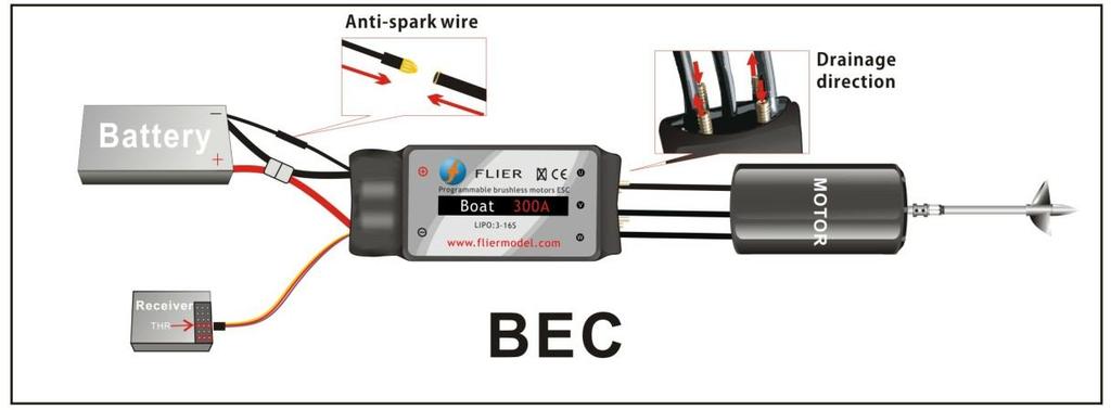
3 2.Timing:0, 1, 2, 3, Frequency: 8KHz, 16 KHz, 32 KHz. 4.Acceleration: Soft / Medium / Hard 5.Accumulator type:nicd/nimh, Li-Ion/Li-Pol, LiFe 6.NiCd/NiMH CUTOFF: 0.05, 0.4V, 0.5V, 0.6V, 0.7V, 0.8V, 0.9V, 1.0V 0.05 means the cut off voltage is 5% the voltage while connecting. 7.Number of cells: Auto, 2S, 3S, 4S, 5S, 6S, 7S, 8S, 9S, 10S, 11S, 12S, 16S, 17S, 18S, 19S, 20S, 21S, 22S, 23S, 24S. 8.LiIo/Pol CUTOFF:2.0V, 2.1V, 2.2V, 2.3V, 2.4V, 2.5V, 2.6V, 2.7V, 2.8V, 2.9V, 3.0V, 3.1V, 3.2V, 3.3V, 3.4V, 3.5V, 3.6V 9.LiFe cutoff:2.2v, 2.3V, 2.4V, 2.5V, 2.6V, 2.7V, 2.8V 10.Cut Off Type::Slow down, Hard 11.Ini point:auto, fixed 1.0mS, fixed 1.1mS, fixed 1.2mS, fixed 1.3mS, fixed 1.4mS, fixed 1.5mS 12.End point:auto, fixed 1.7mS, fixed 1.8mS, fixed 1.9mS, fixed 2.0mS 13.Throttle curve: Logarithmical, Linear, Exponential 14.Rotation direction: Left, Right. 15.Timing monitor (TIMING MONTITOR): ON, Off. Note:the red mark is the factory default value Diagram for wire connection 1. Correctly connect ESC to brushless motor, receiver and battery pack(correctly use the Anti-spark wire while connect the ESC to battery pack). 2. Electronics are correctly power on for the setting 3. Then you will hear or (if you don t hear the first three beeps, pls check your motor, whether the motor wires is connected well or not. The last one beep means the ESC enter to forward mode, the last two beeps means the esc enter to forward and reverse mode, if you can t hear the last one beep or two beeps, pls check your receiver, whether it s connected well or not, and check your remote control). 4. Pushing the trigger, then the motor will start to work. Notice: Correctly use the anti-spark wires. The anti-spark wire including a bullet connector and an anti-spark resistor. So you can separate it into two wires. You must solder the another one to the battery negative. If you want to connect the ESC to the battery, you can connect the red wire of ESC to the positive pole of battery at first. Then connect the anti-spark wires well. The last step is connect the black wire of ESC to the battery s negative pole. If do like that, no spark will be generated, and it will protect the main bullets connector from damaged

4 Function value setting by transmitter - 3 -
5 Group (Bra ke On Mode) or (Brake Off Mode) Param eter Saved and Exit Progra mming Mode This series ESC can be set some simple function value by transmitter, but the more function value setting must be by prog-box or PC via USB link wire This ESC gets two different types of mode, one is Brake ON mode, and another is Brake Off mode. Change mode setting procedure as follows: 1.Move throttle stick on full power position, turn on transmitter. Now when switching on the ESC, programming sequence will start. 2.Connect the power battery, turn on receiver. 3.After approx. 5 seconds, a four-tone melody can be heard; this indicates that a programming sequence is ready. 4.And then you will hear 5 groups (a short beep), then 5 groups, then 5 groups and then 5 groups ; and 5 groups,5 groups -(a long - 4 -

6 beep),5 groups. And these sounds of groups will circulate 5.Each group of 5 sounds stands for a different mode of ESC respectively. 6.You can put the throttle stick to the middle position during one group of 5 sounds, and then the corresponding mode is saved. 7.Hear 1 (Forward mode) or " " (Forward/Reverse mode), then you can exit the setting mode after saving the mode. (When the mode is saved, you can disconnect the ESC to the battery pack) Brake On mode and Brake Off mode: Hear the first,put the throttle stick to the middle position, the mode is changed from Brake ON mode into Brake off mode. If you want to change back, please repeat the above procedures, and vice versa. Timing(motor ignition advance)function value: 1.Hear 5 groups or or or in the above circulation, put the throttle stick to the middle position. 2.Timing mode 1: 5 groups ----0~7 (recommended for 2 poles and common motors) 3.Timing mode 2: 5 groups ----8~15 (recommended for 4 poles motors) 4.Timing mode 3: 5 groups ~23 (recommended for 8 poles motors) 5.Timing mode 4: 5 groups ~30 (recommended for more than 10 poles motors and out runner motors) Setting of Frequency: 1.Hear 5 groups - or 5 - or 5 in the above circulation, put the throttle stick to the middle position. 2.Frequency 1: 5 groups khz ((For common setting, the lowest efficiency loses) 3.Frequency 2: 5 groups khz (recommended for the low internal resistance of motor) 4.Frequency 3: 5 groups khz (recommended for the low electrical inductance of motor) Note: when the timing of motor is saved, please adjust motor on the ground before the flight (Diagram for Option parameter assistant by transmitter) Function value setting by Program-Box By the Flier Program Box, you can set all of function value very simply.setting procedure as follows: 1. Connect the 4pin connector of ESC with the 4PIN connector in Prog-Box. Make sure the direction is correct
7 2.Connect ESC and motor. 3. Power on the ESC, and you will hear a melody, it prompt that the connecting is ok and you can go on. 4. Great! Read ESC Data OK will be displayed on the LCD screen(on the front of the Box). after 1 second, it will enter the first function-mode TYPE setting interface automatically. Then your esc type can be displayed on the LCD screen. and buttons make no difference because the ESC type can t be changed. 5. Press Forward button to enter the second function item-controller TYPE. The ESC type which you purchased will be displayed on the LCD screen. and buttons make no difference because the ESC type can t be changed. 6. You can press Forward button enter desired function item,then press and button enter desired value. You also can press Back button, then back to the last function item. 7.All setting is done. The LCD screen will display Sending Data to ESC if you press Back and Forward buttons. It prompt the setting value have sent to the ESC. 8. Turn off the power of the esc, and connect the power. You can inspect whether the function values were wrote in the ESC or not. 9.After setting over, turn off the ESC, disconnect the Prog-Box. Setting is done. Note:if the ESC you are setting is no BEC, you will have to power to the Prog-Box via another 3pin connector Function value setting by PC An excellence in this series ESC is that they can be set function value via PC. By a match software designed our company, via a USB Linker, a ESC can communicate with PC, then you can Easily set the ESC function value on PC screen

8 If use firstly, you must install the USB Linker driver and the ESC setting software. Installation of USB Linker driver The below are the instructions of how to install the driver under Windows XP, 1. Firstly plug the USB linker into the USB port on the computer. The computer will automatically detect the USB linker and ask for installation of the USB driver. The computer screen shows the window Found new hardware wizard. Press Next button. 2. Please select Install from a list or special position (Advanced) and press Next button. 3. Please select Search for the best driver in these locations and check Include this location in the search. In the search dialog specify the location of the USB driver that is located in the CD or driver download folder USB driver. 4. The above steps probably need to be repeated. If any same prompt appear, please repeat the installation steps carefully until the installation process is complete. 5. Open Windows Device Manager. (Control panel C system C device manager) 6. Find "Ports (COM & LPT)" in the list and click the + sign to its left. 7. Find the line that reads Prolific USB-to-Serial Comm. Port (COMX)". The "x" value is the COM port number that was assigned to the USB to serial converter. This is the port that will need to be selected in the Flier ESC Computer Linking Software. Make note of it

9 Note:different computer will have different the number of COM port, remember it, you will use the number in the ESC setting software Flier ESC Computer Linking Software Installation The installation of Flier ESC Computer Linking Software is as the same as the normal Windows software. In windows system, you run simplify setup file, and then install it easily according to the prompt. After installation finish, you can run the software. Only after the Flier USB linker connects the Flier ESC to the computer, the software can be operated. Flier ESC Computer Linking Software Interface Overview 1. The top-left of the interface is Select COM Port, ESC type, this will be for comport select and the Flier ESC type display. 2. The top-middle of the interface is a text box. it can display some messages of the software progress. 3. The middle main area of the interface is the program area. You can program the setting value of the ESC here. 4. The top-right of the interface is a write data button. You can press it to write the setting value into the ESC. 5. The bottom of interface displays the copyright and company website information. How to program the ESC 1. This is very important. Disconnect the battery, the motor and the receiver. I.e. disconnect all connections of the ESC. 2. Launch the Flier ESC Computer Linking Software. You can see a interface which the above mention. Because the Flier ESC is not connected, the interface isn t operated now. 3. Plug your Flier USB linker into the computer, and if the USB linker driver has been installed correctly. The com port can be automatically selected, the automatic selection usually is right, but some computer have too many com port is using. An error com port selection is possible, in this condition; you must select the correct com port which the - 8 -


10 above mention. 4. Connect the 4pin wires of the USB linker to the 4pin wires of the ESC, pay attention to the color of the wires, must ensure the same color wires connect together, or you will possibly damage the ESC. If you connect correctly, the Flier ESC type will display in the ESC type column. If don t display correctly, you can pull the 4pin wires and plug again, till the display is correct. 5. You can see the setting value in the Flier ESC will display the program area. So you can easily know the setting value of the ESC at current. 6. You can change any setting value from the program area; you also can press the load factory default text to load the factory default value. 7. After you finish your adjustment. Press the top-right write button, your setting value will write into the ESC. 8. Disconnect the 4pin wires, 9. Exit the flier ESC computer software, 10. Pull out the USB liker. Now, your ESC has been programmed. Update the firmware of the ESC 1, Plugging the USB Linker wires,be sure that the USB linker wires driver was installed, 2.Running the software, click the "Flash" button. After a "Download ESC type OK"message displays in the text box, you can reboot the software. (The second step must be done, if not, the firmware types which you need for the ESC can't be recognized). 3. Choosing the correct port from "Select COM Port", 4. Choose the firmware which you want, the next step is click "Down Load File" button. "File read OK!".Message will appear. 5. Disconnect the power of the ESC and BEC. 6. Plugging 4pin of the ESC into the 4 pin of USB Linker. "Connect OK, Please..." message - 9 -

11 will appear. 7.If any errors pull out 4pin wires then repeat step 6 still correct message. 8. Clicking Write" button. the ESC will be updated software now. 9. Waiting, until "update to 113 pages, errors pages 0... tell you the updated software succeed. 10. You can disconnect the 4pin of the ESC from the USB Linker
FLIER. User s Manual. ESC for Boat 2S to 22S FLIER
 FLIER User s Manual Tel:+86-0755-27905140 Business:sale@fliermodel.com Technic support:james@fliermodel.com Sales:Cathy@fliermodel.com/Lisa@fliermodel.com Skype:Fliermodel ESC for Boat Manual Thank you
FLIER. ESC for Boat 2S to 22S. User s Manual FLIER
 FLIER User s Manual Tel:+86-0755-27905140 Business:sale@fliermodel.com Technical support:james@fliermodel.com Sales:Cathy@fliermodel.com/Lisa@fliermodel.com Skype: Fliermodel ESC for Boat Manual Thank
Flier ESC Program box
 Flier ESC Program box User s Manual www.fliermodel.com Tel:+86-0755-27905140 Business:sale@fliermodel.com Technical support:james@fliermodel.com Sales:Cathy@fliermodel.com/Lisa@fliermodel.com Skype: Fliermodel
SUPER BRAIN ESC-100A Brushless Speed Controller INSTRUCTIONS
 SUPER BRAIN ESC-100A Brushless Speed Controller INSTRUCTIONS Thanks so much for purchasing Turnigy Super Brain speed controllers. Please read the instruction booklet carefully before flying to ensure to
Kingkong ESC Manuals
 Kingkong ESC Manuals Thanks so much for purchasing Kingkong-series speed controllers manufactured by Chongqing HIFEI Technology Ltd., please read the instruction booklet carefully before flying to ensure
ASSAN ESC PC Interface Software User s Guide
 ASSAN ESC PC Interface Software User s Guide Dear customer, Welcome to use ASSAN ESC PC Connector and Interface Software. It allows of the Electronic Speed Controller programming in the desktop PC and
200A-K Brushless Speed Controller INSTRUCTIONS
 200A-K Brushless Speed Controller INSTRUCTIONS Thanks so much for purchasing Kingkong-series speed controllers manufactured by Chongqing HIFEI Technology Ltd., please read the instruction booklet carefully
20A 4 in 1 + CC3D FC. Connection diagram (To flight controller) Connection diagram 2 BATTERY GND VCC. black red. red yellow black.
 Connection diagram 2 BATTERY GND VCC. black red. red yellow black.") 4 in 1 + CC3D FC Connection diagram (To flight controller) Blue 1 Green 2 Yellow 3 White 4 Red 5 Black 6 6 5 4 Inputs 1~6 3 2 1 5V -Neg Top Botton Connection diagram 2 4 Brushless Motor 3 Brushless Motor
4 in 1 + CC3D FC Connection diagram (To flight controller) Blue 1 Green 2 Yellow 3 White 4 Red 5 Black 6 6 5 4 Inputs 1~6 3 2 1 5V -Neg Top Botton Connection diagram 2 4 Brushless Motor 3 Brushless Motor
PRO ESC - LCD PROGRAM CARD USER MANUAL. The Fantom FR-10 PRO LCD Program Card only applies to the FR-10 PRO 1:10 scale, 2S, 160A brushless ESC.
 PRO ESC - LCD PROGRAM CARD USER MANUAL The Fantom FR-10 PRO LCD Program Card only applies to the FR-10 PRO 1:10 scale, 2S, 160A brushless ESC. The LCD Program Card can be used in two ways as follows: 1.
X-CAM A10-3H 3 Axis Gimbal for GOPRO. User Manual ( V2.00 )
") X-CAM A10-3H 3 Axis Gimbal for GOPRO User Manual ( V2.00 ) The X-CAM A10-3H 3 Axis Gimbal has been setup and calibrated for use with GOPRO cameras, it is ready to use straight from the box. Specifications:
X-CAM A10-3H 3 Axis Gimbal for GOPRO User Manual ( V2.00 ) The X-CAM A10-3H 3 Axis Gimbal has been setup and calibrated for use with GOPRO cameras, it is ready to use straight from the box. Specifications:
Hitec 2.4 GHz System Firmware Update Manual
 Hitec 2.4 GHz System Firmware Update Manual 1. HPP-22 Download and Installation Instructions 2. Aurora 9 V 1.07 Firmware Upgrade Procedure 3. SPECTRA 2.4 V 2.0 Firmware Upgrade Procedure 4. SPECTRA 2.4
Product Overview... 3 Items Included... 3 Precautions... 4 Minimum System Requirements... 4 Software Installation... 5 Software Registration
 Version 1.2 8/23/2010 TABLE OF CONTENTS Product Overview... 3 Items Included... 3 Precautions... 4 Minimum System Requirements... 4 Software Installation... 5 Software Registration... 6 NovaLink Instructions...
FT2DR/DE. DSP Firmware Update Instruction Manual YAESU MUSEN CO., LTD.
 FT2DR/DE DSP Firmware Update Instruction Manual YAESU MUSEN CO., LTD. Introduction This application is a software tool for updating the firmware of transceivers manufactured by Yaesu Musen Co., Ltd. CAUTION!
AccuPOS Hardware Setup Guide TABLE OF CONTENTS
 AccuPOS Hardware Setup Guide TABLE OF CONTENTS 1. Receipt Printer (TSP 100) a. Unpacking b. Parts Identification c. Hardware setup and Cable connection d. Software Setup e. Configuring Receipt Printer
3700 SERIES USER MANUAL
 SAFETY GUIDE This manual contains the precautions necessary to ensure your personal safety as well as for protection for the products and the connected equipment. These precautions are highlighted with
For Auto Locksmith Association only!!! Emergency Service Manual.
 For Auto Locksmith Association only!!! Emergency Service Manual = OBD Key Programmer + OBD Alarm Disarming tool = ====================================================================== Models: AUDI A4
Voice Pager MODEL:VP101
 Voice Pager MODEL:VP101 Contents Contents Getting Started...1 Equipment Required... 1 Programming Setup... 1...6 Introduction... 6 Start the Programming... 6 May 17, 2011 V1.2 Getting Started Getting Started
THIS IS THE CURRENT FF USER GUIDE AS OF PLEASE DO NOT USE ANY PREVIOUSLY DATED VERSIONS
 THIS IS THE CURRENT FF USER GUIDE AS OF 05-04-2012 PLEASE DO NOT USE ANY PREVIOUSLY DATED VERSIONS INTRODUCTION: I compiled this guide from information posted on RCGroups.COM and from GoodLuckBuy.COM where
Troubleshooting Guide
 Troubleshooting Guide Troubleshooting Communications With the SilverLode product powered up, start QuickControl and the polling routine should automatically find the device. If QuickControl is already
THIS IS THE CURRENT FF USER GUIDE AS OF PLEASE DO NOT USE ANY PREVIOUSLY DATED VERSIONS
 THIS IS THE CURRENT FF USER GUIDE AS OF 02-26-2012 PLEASE DO NOT USE ANY PREVIOUSLY DATED VERSIONS INTRODUCTION: I compiled this guide from information posted on RCGroups.COM and from GoodLuckBuy.COM where
X-CAM A10-3H for GOPRO 3 Axis Gimbal User Manual
 X-CAM A10-3H for GOPRO 3 Axis Gimbal User Manual X-CAM A10-3H for GOPRO 3 Axis Gimbal has been finished with all the adjustments before launch the market, READY TO RUN. Accessories Parameters Weight: 280g(withoutGOPRO)
Software Setup Instructions for the Foster Control System used in the Explora Dome Observatories
 Software Setup Instructions for the Foster Control System used in the Explora Dome Observatories Contents Pages 3 & 4 The new tic counter system & home position sensor Page 5 Control Boxes Pages 6-8 Down
A.1 MD-CC USB to SPI communications
 A.1 MD-CC305-001 USB to SPI communications The MD-CC305-001 is an interface cable which combines Power, Logic and communications with an inline USB to SPI converter. It is recommended with the first purchase.
Assigning COM Port Numbers to the Serial Ports of a USBto-Serial
 Assigning COM Port Numbers to the Serial Ports of a USBto-Serial Adapter A Technical Application Note from Doppler Systems May 6, 2008 1.0 Introduction USB-to-serial converters have an interesting and
AX1500. Dual Channel Digital Motor Controller. Quick Start Manual. v1.9b, June 1, 2007
 AX1500 Dual Channel Digital Motor Controller Quick Start Manual v1.9b, June 1, 2007 visit www.roboteq.com to download the latest revision of this manual Copyright 2003-2007 Roboteq, Inc. SECTION 1 Important
SEIKA. Trans Braille 40 Braille Display. User s Manual Version 3.36
 SEIKA Trans Braille 40 Braille Display User s Manual Version 3.36 Preface Thank you very much for purchasing a Trans Braille 40, Seika Braille Display. This Braille display enables pins to display characters
USB-Link 2 Technical Guide
 www.wattmaster.com USB-Link 2 USB-Link 2 Code: SS0073 Version 4.11 and up Table of Contents General Information... 3 USB-Link 2 Overview...3 System Requirements...3 Quick Guide... 4 USB-Link 2 Driver Installation
BATTERY TESTING SYSTEM
 BATTERY TESTING SYSTEM Operation Manual AA Portable Power Corp 860 South 19 th Street, Richmond, CA 94804, USA TEL: (510)525-3070 FAX: (510)525-4705 Website: Batteryspace.com email:sales@batteryspace.com
NX-588E USB Flash Programmer Instructions v1.1
 NX-588E USB Flash Programmer Instructions v1.1 Installing the NX-588E on a computer This process should take 5-10 min. 6. The following screen will appear: It is essential you carry out this step from
Programming adapters for BLHeli
 - 1 - v1.1 Programming adapters for BLHeli This document describes the various adapters that can be used together with the BLHeliSuite PC based software for flashing and programming parameters of BLHeli
WinMarkpro v6 for the FH Marking Head Quick Start Guide
 Important See the FH Flyer Marking Head (MH) Operators Manual for complete installation details and instructions. A PDF version is available online at: http://www.synrad.com/manuals/ manuals_laser.htm.
trakpowerusa.com/escprogramming/index.html
 MS Connect by TrakPower is PC based set-up software compatible with TrakPower MS Series electronic speed controls. Instruction Manual The MS Connect opens up a new world of tuning options not accessible
USB-COMi-TB USB to Industrial Single RS-422 / 485 Adapter Manual. Specifications and Features
 USB-COMi-TB USB to Industrial Single RS-422 / 485 Adapter Manual The USB-COMi-TB USB-to-Industrial Single RS-422/485 Adapter is designed to make industrial communication port expansion quick and simple.
MC601C Link Program Manual
 USB INTERFACE MC601C Link Program Manual *Note:The MC601C Link program is for Windows Vista/XP/2000 use and is not compatible with other OS. Downloaded Zip file extraction (decompression)...p2 Extracted
Data setting software MEXE02
 HM-40143 Data setting software MEXE02 OPERATING MANUAL Before Use Thank you for purchasing an Oriental Motor product. This operating manual describes product handling procedures and safety precautions.
Instruction It can display battery voltage, discharge current, time, battery
 Feature: Instruction NC, constant current battery discharge instrument It can display battery voltage, discharge current, time, battery capacity, power, total power, resistance Auto remember the last set
SeaViewer Cameras, Inc. DVR-SD. SD Digital Video Recorder. User s Manual
 SeaViewer Cameras, Inc. DVR-SD SD Digital Video Recorder User s Manual Please read this User s Manual carefully to ensure that you can use the device correctly and safely. The contents of this manual are
Scorpius User Manual Version 3.0. Part 1:Controller Part 2: Car Decoder Part 3: Lane Brain Part 4: WAM (Wireless Analogue Module) Part 5: Dongle
 Part 5: Dongle") Scorpius User Manual Version 3.0 Part 1:Controller Part 2: Car Decoder Part 3: Lane Brain Part 4: WAM (Wireless Analogue Module) Part 5: Dongle Part 1: Controller Knobs 1)Sensitivity Scroll to choose
Scorpius User Manual Version 3.0 Part 1:Controller Part 2: Car Decoder Part 3: Lane Brain Part 4: WAM (Wireless Analogue Module) Part 5: Dongle Part 1: Controller Knobs 1)Sensitivity Scroll to choose
R-DAS Tiny User s Manual
 R-DAS Tiny User s Manual Scope This document is an addendum to the R-DAS manual and is specific to the R-DAS Tiny (hardware V4.x). For general concepts about the R-DAS, please see the R-DAS Manual. New
Executive summary. Gather up the materials & tools required. Set up the BT2S for the ProChrono baud rate:
 Executive summary On/Off switch A fully self-contained Bluetooth-to-ProChrono interface powered by three AA batteries Steady LED indicates Bluetooth connection Jack connects to ProChrono 1. Gather up the
EM398x-R1 UPS VA
 EM398x-R1 UPS 600-1000-1600VA EM398X-R1 - UPS 600-1000-1600VA 2 ENGLISH Table of contents 1.0 Introduction... 2 1.1 Functions and features... 3 1.2 Packing contents... 3 1.3 Connecting the UPS... 3 2.0
Please read and understand this instruction manual thoroughly before using this product.
 Please read and understand this instruction manual thoroughly before using this product. For Mini-Z ASF 2.4GHz Series and dnano FX Series models I.C.S. Adaptor Set Manual Instruction Manual No. 82080 This
YourBell INEXPENSIVE, RELIABLE USB PRODUCTS.
 YourBell INEXPENSIVE, RELIABLE USB PRODUCTS www.bcsideas.com 1 Table of Contents General Information...3 Installation...3 Software...3 USB Driver...3 Hardware...5 Figure 1 Hardware Over View 6 Figure 2
Application Note Demonstrating the Serial Port Profile (SPP) Between BlueConnect and BTW 2002/5/29
 Between BlueConnect and BTW 2002/5/29") Application Note Demonstrating the Serial Port Profile (SPP) Between BlueConnect and BTW 2002/5/29 1 Introduction As a technology leader in the wireless networking market, WIDCOMM s vision is to enable
Application Note Demonstrating the Serial Port Profile (SPP) Between BlueConnect and BTW 2002/5/29 1 Introduction As a technology leader in the wireless networking market, WIDCOMM s vision is to enable
Centurion PLUS CPC4 Download Guide using C4 File Transfer Utility
 1010537 2010-03-01 Section 50 Centurion PLUS CPC4 Download Guide using C4 File Transfer Utility 1.0 Background 1.1 The Centurion PLUS Control system consists of a Centurion PLUS Core (CPC4-1) and color
CellSync Manager. User Manual F8V7D006-SS F8V7D008-SS. Get online and synchronize anywhere. Web Access. Phone Book Manager
 CellSync Manager Get online and synchronize anywhere Web Access Phone Book Manager User Manual F8V7D006-SS F8V7D008-SS TABLE OF CONTENTS Introduction...2 Interactive Phone Menu...3 LG 5350 CellSync Software
MOST-AUX Fiber-optic AUX input for select MOST vehicles NTV-KIT001/002/007/008/143/151/152
 3950 NW 120 th Ave, Coral Springs, FL 33065 TEL 561-955-9770 FAX 561-955-9760 MOST-AUX Fiber-optic AUX input for select MOST vehicles NTV-KIT001/002/007/008/143/151/152 I N T E R F A C E BHM Overview The
YourBell INEXPENSIVE, RELIABLE USB PRODUCTS. 1
 YourBell INEXPENSIVE, RELIABLE USB PRODUCTS www.bcsideas.com 1 Table of Contents General Information...3 Installation...3 Software...3 USB Driver...3 Hardware...5 Figure 1 Hardware Over View 5 Figure 2
Controller and Programmer to sequential firing detonators in s7 rocket models. Size: 26 x 40 x 12 mm(17mm witch connector)
") Controller and Programmer to sequential firing detonators in s7 rocket models Device was built to sequential firing detonators in s7 rocket models. It is fully programmable device with microprocessor.
Controller and Programmer to sequential firing detonators in s7 rocket models Device was built to sequential firing detonators in s7 rocket models. It is fully programmable device with microprocessor.
Table of Contents -2-
 Arkbird GCS(Ground Control System)is a software specifically designed for Arkbird Autopilot, the aircraft flight can be monitored, controlled by computer, compatible to Arkbird 2.0 and Arkbird LITE Autopilot
Firmware, Database, & PC Application Update Installation Instructions
 Firmware, Database, & PC Application Update Installation Instructions IMPORTANT Please read before you begin the installation. To avoid possible errors, it is recommended to install the updates as described
Firmware, Database, & PC Application Update Installation Instructions
 Firmware, Database, & PC Application Update Installation Instructions IMPORTANT Please read before you begin the installation. To avoid possible errors, it is recommended to install the updates as described
TM LOCKPICK C8 INSTALLATION OPTIONS COPYRIGHT 2011 COASTAL ELECTRONIC TECHNOLOGIES, INC. UNPLUG ORIGINAL RADIO CONNECTORS THEN PLUG IN HERE
 TM LOCKPICK C8 INSTALLATION OPTIONS COPYRIGHT 2011 COASTAL ELECTRONIC TECHNOLOGIES, INC. FACTORY CONNECTORS INCLUDED UNPLUG ORIGINAL RADIO CONNECTORS THEN PLUG IN HERE PLUG AND PLAY NO OTHER CONNECTIONS
ALPHACallisto Discrete Input Setup Guide & User Manual
 ALPHACallisto Discrete Input Setup Guide & User Manual Copyright 2018 Adaptive Micro Systems LLC. All rights reserved. Adaptive Micro Systems 7840 North 86th Street Milwaukee, WI 53224 USA 414-357-2020
Xitron USB Interface Installation August, 2007 Revision 3
 August, 2007 Revision 3 Overview This document describes installing the Xitron USB interface box and the software required to use it. The basic sequence is to install the RIP or plugin, then connect the
Introduction CLASS 1 LED PRODUCT
 Introduction Thank you for purchasing a set of FlightLights, a high performance LED system for model aircraft designed and manufactured by BrainCube Aeromodels Ltd. This manual will describe how to safely
GV-Keyboard Instruction Manual
 Instruction Manual 005/03 Before attempting to connect or operate this product, please read these instructions carefully and save this manual for future use. Table of Contents RX TX Introduction P P P3
Antenna Rotator System USB
 Antenna Rotator System USB ARS-USB Reference Manual June/2012 Rev 1.5d Introduction Thank you for purchasing the ARS-USB Product. Presently, the ARS provides the most powerful highest performance and lowest
SENSORLESS-BLDC-MOTOR-RD
 S ENSORLESS BLDC MOTOR REFERENCE DESIGN KIT USER S GUIDE 1. Kit Contents The BLDC Motor Reference Design Kit contains the following items: BLDC Motor Reference Design Board Brushless DC (BLDC) Motor Universal
Features. Warnings and Precautions READ BEFORE OPERATING EQUIPMENT SAVE THESE INSTRUCTIONS
 SENTA Warnings and Precautions READ BEFORE OPERATING EQUIPMENT SAVE THESE INSTRUCTIONS To prevent damage to your radio or possible injury to you or others, read these safety precautions and instructions
Please read and understand this instruction manual thoroughly before using this product.
 Please read and understand this instruction manual thoroughly before using this product. For Mini-Z ASF 2.4GHz Series and dnano FX Series models I.C.S. USB Adaptor Set Manual Instruction Manual No. 82080
GAUGEMASTER. DCC55 Prodigy Computer Interface
 DCC55 GAUGEMASTER DCC55 Prodigy Computer Interface Thank you for purchasing the Prodigy Computer Interface. It contains the hardware, (USB module) and computer interface software. It will allow your computer
Navigation interface for Jeep GC 5 RA2 NTV-KIT581
 3950 NW 120 th Ave, Coral Springs, FL 33065 TEL 561-955-9770 FAX 561-955-9760 NNG-Jeep GC Navigation interface for Jeep GC 5 RA2 NTV-KIT581 NNG-JEEP GC Kit Content 5 1 6 4 7 2 3 1. 2. 3. 4. 5. 6. 7. 8.
FORTINI F4. Flight Controller USER MANUAL VERSION 1.2
 FORTINI F4 Flight Controller USER MANUAL VERSION 1.2 Please contact us if you need further assistance: Tech support: tech@furiousfpv.com Sales support: sales@furiousfpv.com Website: http://furiousfpv.com/
NISSAN ECU FLASH REPROGRAMMER FOR WINDOWS (Ver. 1.00) INSTRUCTION MANUAL
 INSTRUCTION MANUAL") NISSAN ECU FLASH REPROGRAMMER FOR WINDOWS (Ver. 1.00) INSTRUCTION MANUAL !! NOTE and CAUTION!! Thank you for purchasing the TECHTOM Flash Reprogrammer. Please read and follow the instructions carefully
NISSAN ECU FLASH REPROGRAMMER FOR WINDOWS (Ver. 1.00) INSTRUCTION MANUAL !! NOTE and CAUTION!! Thank you for purchasing the TECHTOM Flash Reprogrammer. Please read and follow the instructions carefully
AFEDRI SDR 192kHz firmware upgrade process description.
 AFEDRI SDR 192kHz firmware upgrade process description. 1. Attention!!! Please run SDR Control software before firmware upgrade process beginning. Switch to tab About and write value of Front End Main
Make a Quadcopter using KK Flight Controller
 Make a Quadcopter using KK 2.1.5 Flight Controller 1 Typical Applications A quadcopter, also called a quadrotor helicopter or quadrotor, is a multirotor helicopter that is lifted and propelled by four
Free Flight Controller User Manual
 Free Flight Controller User Manual 1. Computer Setting The FF(Free Flight Controller, Below same)board default setting is "X mode"+ Start from static,10.8v below voltage alarm enable, if you need change
installation manual SALES AND ADMINISTRATION (toll free)
") installation manual SALES AND ADMINISTRATION 800.637.2645 (toll free) 217.442.0611 sales@timeomatic.com TECHNICAL SUPPORT 866.637.2645 (toll free) service@timeomatic.com www.watchfiresigns.com Quick Start-Up
installation manual SALES AND ADMINISTRATION 800.637.2645 (toll free) 217.442.0611 sales@timeomatic.com TECHNICAL SUPPORT 866.637.2645 (toll free) service@timeomatic.com www.watchfiresigns.com Quick Start-Up
5.6" Multi-function Monitor
 5.6" Multi-function Monitor User s Manual Please read this Manual carefully before use of this product, and keep it handy for future reference. I. Packing List.. 2 II. Product Appearance... 3-5 III. Product
RS Stock No Instruction Manual RS Input Data Logging Thermometer
 RS Stock No. 730-0458 Instruction Manual RS-1384 4 Input Data Logging Thermometer EN FR IT DE ES TABLE OF CONTENTS / EN TITLE TABLE OF CONTENTS PAGE 1. INTRODUCTION FEATURE... 1 2. SPECIFICATIONS... 2
Caution Notes. Features. Specifications. A3-L User Manual V1.0
 Caution Notes Thank you for choosing our products. If any difficulties are encountered while setting up or operating it, please consult this manual first. For further help, please don t hesitate to contact
3001D Smart Safe Manual
 3001D Smart Safe Manual For 3001D-1HL/3001D-3HL/3001D-5HL SUMMARY Thank you for using our company s smart safe. Before you use this product, please read this manual carefully, it will help you to use the
iosd (On Screen Display)
") iosd (On Screen Display) User Manual V2.2 For iosd Firmware Version V3.3 & iosd Assistant V4.1* July, 216 * iosd Firmware V3.3 compatible with iosd Assistant V4.1. www.dji.com 216 DJI All Rights Reserved.
iosd (On Screen Display) User Manual V2.2 For iosd Firmware Version V3.3 & iosd Assistant V4.1* July, 216 * iosd Firmware V3.3 compatible with iosd Assistant V4.1. www.dji.com 216 DJI All Rights Reserved.
Victor BB Comprehensive Guide Preliminary. Revision 1.3
 Preliminary Revision 1.3 Table of Contents 1. Purpose of this Guide... 3 2. Installing the Victor Dashboard... 5 2.1. Installing Serial Drivers... 7 2.1.1. Installing Serial Drivers Prolific PL2303...
Bluetooth/USB Data Logger USER S MANUAL. Hantek 365A/B/C/D/E/F V
 Bluetooth/USB Data Logger USER S MANUAL Hantek 365A/B/C/D/E/F V 1.0.3 www.hantek.com Content General Safety Summary... 1 Chapter 1 Getting Start... 3 1.1 General Check... 4 1.2 The User interface... 5
SF200. Installation Guide & Quick Start Guide. 2 TFT AC Terminal Version: 1.0 Date: June 2014
 SF200 Installation Guide & Quick Start Guide 2 TFT AC Terminal Version: 1.0 Date: June 2014 All design and specification declared are subject to change without notice in advance. Contents Safety Precautions
Quick Start Guide. MS-820 Industrial Bar Code Scanner
 Quick Start Guide MS-820 Industrial Bar Code Scanner This guide is designed to get your scanner up and running quickly. When connected to a host computer with Windows operating system (98 or above), you
FlyChart Installation Guide
 Important: Do not connect the flight instrument to the computer until you have finished Step 1 and 2 of this software installation guide! This installation guide is for FlyChart v4.52.32 and later and
TigerStop Ethernet-to-Serial Converter Installation & User s Guide v4.2
 E1 / 2010 ESC 4.2 TigerStop Ethernet-to-Serial Converter Installation & User s Guide v4.2 September 2010 TigerStop Version 5.03+ CONTACT: TigerStop LLC, Assembly Plant, 12909 NE 95 th St., Vancouver, WA
Professional Entertainment Technology. imove 50SR. Innovation, Quality, Performance 21-
 Innovation, Quality, Performance 21- imove 50SR User Guide Professional Entertainment Technology EC Declaration of Conformity We declare that our products (lighting equipments) comply with the following
SmartPick Service Interface Installation, Setup and Event Log Download, Windows 7 & 8
 Seite: 1/14 SmartPick Service Interface Installation, Setup and Event Log Download, Windows 7 & 8 1 Introduction 2 2 Flowchart 3 3 Installation 4 3.1 Installing the USB to Serial Adapter 4 3.2 Installing
PC Focus Control Operator's Guide
 PC Focus Control Operator's Guide Copyright 2008 JMI Telescopes Jim's Mobile, Incorporated 8550 West 14th Avenue Lakewood, CO 80215 U.S.A. Phone (303) 233-5353 Fax (303) 233-5359 Order Line (800) 247-0304
USB-Link Technical Guide
 www.wattmaster.com USB-Link Technical Guide USB-Link Code: SS0070 Table of Contents General Information... 3 USB-Link Overview...3 System Requirements...3 Quick Guide... 4 Connection and Wiring... 5 USB-Link
Dot Matrix Indicator Programming
 Dot Matrix Indicator Programming Preparation: USB Dongle and USB cable. Part No. 100-159 (see page 3 Dongle Installation Instruction ). Display Programmer V2.0 (see page 10 Display Programmer V2 Installation
ARRIS Zhao Yun Pro User Manual. Content
 ARRIS Zhao Yun Pro User Manual Thank you for buying ARRIS Zhao Yun Pro 3-Axis brushless Gimbal. Each gimbal has been adjusted and tested before we send it out. For this gimbal, Most customers can plug
LAZER Model 905K USER GUIDE
 Specification This product is designed for use in Great Britain and complies with the European Low Voltage and EMC Directives. For a copy of the Declaration of Conformity for this product, please write
LV8548MCSLDGEVB. Brush DC Motor Driver Module Solution Kit Quick Start Guide
 LV8548MCSLDGEVB Brush DC Motor Driver Module Solution Kit Quick Start Guide Overview The LV8548MCSLDGEVB is an ON Semiconductor motor driver module featuring the LV8548MC. This module is capable of easily
SmartVR. Quick Start Guide. Release 2.0
 SmartVR Quick Start Guide Release 2.0 www.veear.eu Table of Contents Introduction Read this first!... 3 SmartVR Product Description... 3 Hardware Setup... 4 Software Installation... 5 Running your first
USB DIGITAL VOICE RECORDING PEN IN GOLD
 USB DIGITAL VOICE RECORDING PEN IN GOLD SKU: PrmaMQ72N (256) (1GB) THANK YOU FOR PURCHASING THE USB DIGITAL VOICE RECORDING PEN IN GOLD Please read this manual before operating the digital voice recording
SmartFPV RC Camera Control v2. User Guide (RCCC v2 without option to power cameras from RC receiver)
") SmartFPV RC Camera Control v2 User Guide (RCCC v2 without option to power cameras from RC receiver) 6/9/2013 INTRODUCTION SmartFPV RC Camera Control board (RCCC) is multifunctional RC control board designed
SmartFPV RC Camera Control v2 User Guide (RCCC v2 without option to power cameras from RC receiver) 6/9/2013 INTRODUCTION SmartFPV RC Camera Control board (RCCC) is multifunctional RC control board designed
LAZER Model 906K USER GUIDE
 Specification This product is designed for use in Great Britain and complies with the European Low Voltage and EMC Directives. For a copy of the Declaration of Conformity for this product, please write
Figure 1. Proper Method of Holding the ToolStick. Figure 2. Improper Method of Holding the ToolStick
 TOOLSTICK C8051F560 DAUGHTER CARD USER S GUIDE 1. Handling Recommendations To enable development, the ToolStick Base Adapter and daughter cards are distributed without any protective plastics. To prevent
Please read and understand this instruction manual thoroughly before using this product.
 Please read and understand this instruction manual thoroughly before using this product. For Mini-Z ASF 2.4GHz Series and dnano FX Series models I.C.S. USB Adaptor Set Manual Instruction Manual No. 82080
ADP-1122A Display User Manual
 ADP-1122A Display User Manual Release Date Revision Jan. 2013 V1.0 2013 Aplex Technology, Inc. All Rights Reserved. Published in Taiwan Aplex Technology, Inc. 15F-1, No.186, Jian Yi Road, Zhonghe District,
Instructions for Installing FlashUpdate and Downloading Updates for Super Buddy Satellite Meter
 Instructions for Installing FlashUpdate and Downloading Updates for Super Buddy Satellite Meter Updates to the Field Guide and to the instrument firmware are available from the Applied Instruments website.
PULSAR-EQmini v 1.03
 PULSAR-EQmini v 1.03 10.12.2011 Pulsar-EQmini is a professional, CPU controlled equalizer-balancer and cell tester for all Li-xxx cells. Pulsar-EQmini is capable of highly accurate and extremely fast extremely
Modem Installation and Networking Instructions
 Modem Installation and Networking Instructions P/N 36870 Rev F Introduction The following instructions cover connecting a phone line to an incoming phone source, installing a modem, and setting up a network
If I wanted to connect an LED and little light bulb and have them switch on and off with one switch, my schematic would look like the one below.
 Relays Relays are great tools for turning on and off entire circuits, either with a small control switch, or with a microcontroller like the Arduino. To understand how relays are useful and how to control
GV-Keyboard. User's Manual V2.0
 GV-Keyboard User's Manual V2.0 Before attempting to connect or operate this product, please read these instructions carefully and save this manual for future use. 2007 GeoVision, Inc. All rights reserved.