FX3U-20SSC-H Quick start
|
|
|
- Britton McKinney
- 6 years ago
- Views:
Transcription
1 FX3U-20SSC-H Quick start
2 Table of Contents: 1. Introduction 2. Components required for Setup 2.1. Hardware Requirements Components Setup Wiring 2.2. Software Requirements Components 3. Explanation of System Configuration 3.1. Memory Configuration 4. Begin to Use FX3U-20SSC-H with FX Configurator-FP 4.1. Initialization Process Setting the Positioning Parameters Setting the Servo Parameters 4.2. Using TEST MODE JOG Operation Setting the Zero Point Positioning at 1-step speed 4.3. Creating Table Operations 4.4. Using Monitor Mode Table Monitor Operation Monitor 4.5. Resetting an Error 4.6. Absolute Position Detection System 5. Clearing Servo Warning E6 6. Example program with GX Developer
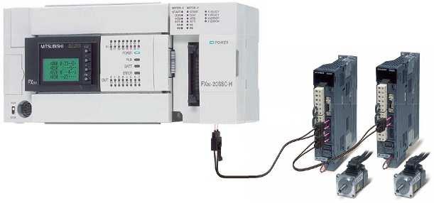
3 1. Introduction Based on customer demand, the FX3U-20SSC-H was developed and introduced to the world as a high performance, cost effective solution for positioning applications in the Micro PLC range of factory automation. The unit s features and capabilities are very similar to the QD75MH2 positioning module, which was developed for the Q Series automation platform CPUs. To setup and program the FX3U-20SSC-H for basic positioning operations, FX Configurator-FP and GX Developer or GX IEC Developer can be used with a personal computer. This quick start guide provides an overview of the hardware and software involved and describes how to set up a system and understand the device communication. FX Configurator-FP is used for initializing hardware parameters, setting up positioning tables, and for testing and monitoring the FX3U-20SSC-H. Please refer to the FX Configurator-FP Operation Manual (JY997D21801A) for further help. Related Documents FX Configurator-FP Operation Manual (JY997D21801A) FX3U-20SSC-H User s Manual (JY997D21301C) 2. Components required for Setup 2.1 Hardware requirements Components FX3U Series Main PLC FX3U-20SSC-H MR-J3-_B servo amplifier HF-MP/HF-KP or HF-SP servo motor MR-J3BUS_M fiber optic cable Programming cables (SC-09, USB) Setup With an FX3U Base Unit attached to the FX3U-20SSC-H, up to eight FX3U-20SSC-H modules can be connected via extension cables to the FX3U. The FX3U-20SSC-H requires DC power and SSCNET III communication for operation. Manual pulse generator dial(s) are optional. For connection to MR-J3-B type servo amplifiers, please refer to the MELSERVO-J3 Series MR-J3- B Servo Amplifier Instruction Manual (SH(NA) ). A basic wiring overview is explained in the following section.
 Fiber optic cable SSCNET 3at CN1A and CN1B Wiring requirements for FX3U-20SSC-H: 24 V DC to power connector Fibre optic cable at SSCNET3 connector")
4 2.1.3 Wiring Wiring requirements for MR-J3-B: 200~230V AC to L1, L2, L3 for power circuit 200~230V AC to L11 and L21 for control circuit Power cable between motor and amplifier (U,V,W terminal) Encoder cable between motor and amplifier (CN2) Fiber optic cable SSCNET 3at CN1A and CN1B Wiring requirements for FX3U-20SSC-H: 24 V DC to power connector Fibre optic cable at SSCNET3 connector Extension cable to FX3U (module takes 100mA from the 5V DC Bus)
5 2.2 Software requirements Components FX Configurator FP Version 1.00 or later (optional, but needed of using this document) GX Developer Version 8.23Z or later or GX IEC Developer Version 7.00 or later 3. Explanation of System Configuration 3.1 Memory configuration The F3U-20SSC-H has two types of memory for initial data transfer processes and continuous communication with servo equipment and programming devices. The module s flash memory retains parameter information and table data for initializing servo equipment at power-on while the buffer memory (BFM) constantly communicates with servo equipment and PLC sequence programs. To set up positioning parameters, servo parameters and table information for the F3U-20SSC-H, it is necessary to send data to the module from a PLC sequence program or from FX Configurator-FP. Due to the convenience and reduced complexity of program coding, FX Configurator-FP should be used whenever possible to program table operations. Below is a diagram of how the 20SSC-H memory communicates with servo amplifiers, PLCs and other equipment.
6 20SSC-H System Communication No. Description (1) Read/Write/Monitor/Test the sequence programs with GX (IEC) Developer. (2) Read out the following data from the FX3U-20SSC-H BFM to FX Configurator-FP. Positioning parameters Servo parameters Table information Monitor data (Operation status, motion status, input signal status, etc.) (3) Write the following data from FX Configurator-FP to the FX3U-20SSC-H BFM. Positioning parameters Servo parameters Table information Control data (The present value change, speed change and operation test command, etc.) (4) Read/Write the following data in BFM with sequence program. Positioning parameters Servo parameters Table information Monitor data (Operation status, motion status, input signal status, etc.) Control data (The present value change, speed change and operation test command, etc.) (5) Store the following BFM data to the Flash ROM by the store command from a sequence program, FX Configurator-FP. Positioning parameters Servo parameters Table information (6) Positioning/servo parameters and table information transfer from the Flash ROM to the BFM at power ON. Simultaneously, servo parameters transfer to the servo amplifiers. (7) Servo parameters in the BFM transfer to the servo amplifiers at power ON. (8) FX3U-20SSC-H retrieves the servo parameters changed by the servo amplifiers and updates the servo parameters in its BFM. In this document, sections of the FX3U-20SSC-H BFM are referred to as: Positioning parameters Servo parameters Table information Monitor data Control data The positioning parameters, servo parameters and table information can be read and written with several devices including FX Configurator-FP, GX (IEC) Developer and human machine interfaces. The monitor data can only be read from the BFM (except for the current address, which has write access), while the control data can be read and written to the BFM. Control data is written to the BFM very frequently, while positioning parameters, table information and servo parameters are usually set up less frequently. For a list of how the areas of the buffer memory can be accessed in terms of read/write, please refer to the following table.
7 Read/Write Properties for the 20SSC-H Buffer Memory BFM # Content R/W 0 99 X-axis Monitor Data R * Y-axis Monitor Data R * Undefined R X-axis Control Data R/W Y-axis Control Data R/W Undefined R X-axis Table Information R/W Y-axis Table Information R/W XY-axis Table Information R/W Undefined R X-axis Positioning Parameters R/W Y-axis Positioning Parameters R/W Undefined R X-axis Servo Parameters R/W Y-axis Servo Parameters R/W Undefined R System Use Only R *1: R/W is possible for the Current address (user) in BFM #1,#0 and BFM #101,# Begin to Use FX3U-20SSC-H with FX Configurator-FP 4.1 Initialization Process When setting up the F3U-20SSC-H for the first time or when beginning a new project, it is recommended to clear the servo parameters and positioning parameters and then write the desired settings (as needed by the user application) to the controller. The purpose of this section is to define basic settings for the initial testing of the module using the FX Configurator-FP software. 1) Confirm that the hardware is set up correctly (as described in Section 2.1: Hardware Requirements) and the PLC is in STOP mode. Turn the power ON. (Both of the servos should display Ab when the power is turned ON for the very first time.) 2) Open FX Configurator-FP from the Start menu [Start MELSOFT Application FX Configurator-FP] or from the Tools menu of GX Developer [Tools FX special function utility FX Configurator-FP] and create a New file by clicking on the Toolbar. 3) Expand the tree of folders in the File data list panel on the left-hand side by double clicking on Unset file, Edit and Monitor. 4) Go to [Online Connection setup Comm. Test.] Verify that the devices are communicating properly. 5) Go to [Online Initialize module.] in

8 Select all servo parameters, positioning parameters and table information and place a check mark in Flash ROM write. Click the OK button and proceed with selecting Yes and then OK. Select all information to initialize the 20SSC-H for the first time. 6) Set the positioning parameters Double click on Positioning parameters in the File data list panel on the lefthand side to modify the positioning parameters. Change the following items from the Item column: Positioning parameters Maximum speed Hz for X- and Y-axes. Positioning parameters OPR mode 1: Data set for X- and Y-axes. (This setting is used specifically for a system without a DOG or mechanical zero-point.) Positioning parameters OPR interlock setting 0: Invalid for X- and Y-axes. (This is used to ensure that the START command functions regardless of the zero return complete flag s Status (BFM#28/128, b3).)
9 7) Set the servo parameters (20SSC-H v.1.04 and later) 7.1) When FX Configurator-FP is used and the forced stop is NOT being used: If a forced stop switch is not used with the MR-J3-B servos, the servo forced stop setting must be disabled before the servo series is set with the Configurator-FP as follows: Double click on Servo parameters in the File data list panel on the left-hand side to modify the servo parameters. Be sure to change settings for BOTH the X & Y axes. Set the following item from the Kind column: Servo parameters Basic setting parameters Function selection A-1 Servo forced stop selection 1: Invalid (Do not use the forced stop signal.) for X- and Y-axes. Write the servo parameters to the 20SSC-H BFM and Flash ROM by pressing the Write to module button or by using [Online Write to module (Ctrl+T).] Select only the servo parameters and put a check mark in the Flash ROM write box as shown below. Click the OK button and proceed with selecting Yes and then OK. Only the Servo parameters are selected to be written. Reboot the power to the SSCNET system. Servo parameters Servo amplifier series Servo amplifier series 1: MR-J3-B for X- and Y axes. Check Flash ROM write so that these settings are active every time the power is turned ON.
10 8) Write the servo and positioning parameters Write the servo parameters and positioning parameters to the FX3U-20SSC-H by pressing the Write to module button or by using [Online Write to module (Ctrl+T).] Select only the servo and positioning parameters and put a check mark in the Flash ROM write box as shown below. Click the OK button and proceed with selecting Yes and then OK. Select the Positioning and Servo parameters to be written. Check Flash ROM write so that these settings are active every time the power is turned ON. 4.2 Using TEST MODE Verify that the PLC is in STOP mode before proceeding with this section. To enter TEST MODE, press the Test On/Off button in the Test toolbar or go to [Online Test Test On/Off.] Select Yes, and then OK. Open up the X- and Y- axis Operation test windows by clicking on the two buttons: and JOG Operation, X-axis In the X-axis Operation test window, click on the JOG/MPG tab. Click and hold down the FWD JOG button. Try changing the JOG speed and JOG instruction evaluation time. (For more information on the JOG instruction evaluation time, refer to Chapter in the FX3U-20SSC-H User s Manual (JY997D21301A).) Setting the Zero Point Click on the X-axis and Y-axis OPR tabs and then click the REQ. OPR button and select Yes and OK. Since the mechanical zero return mode has been set to the data-set type from Section 4.1: Initialization Process, the value in BFM# 14028, (initially zero) is directly written to the current address. (In stopper type and DOG type mechanical zero return modes, this method will cause the motor to turn in the direction of the zero point and will not write zero until the motor comes to a complete stop after detecting an external DOG signal or stopper device. If the REQ. OPR button causes the motor to rotate continuously, verify that the Data-set OPR mode has been set in the Positioning Parameters as described in Section 4.1: Initialization Process.)

11 WARNING: In OPR modes other than Data-set type, the motor will not stop without an external DOG signal or stopper device. X-axis Y-axis Select OPR tab and then REQ. OPR Positioning at 1-Step Speed By default, the FX3U-20SSC-H is set in Absolute positioning mode. If Incremental positioning (Relative positioning) is desired, a table operation or PLC sequence program must be used to specify the Incremental mode. The following procedure uses the default Absolute positioning mode and is meant to be followed step-by-step. Positioning at 1-step speed Set the zero-point according to Section 4.2.2: Setting the Zero Point above if you haven t already done so. Click on the Position start tab and select Positioning at 1-step speed in the X-axis Pattern drop-down menu. Set the following X-axis information: Target address 1: Operation speed 1: 50,000,000 PLS 10,000,000 Hz Click on the Start button and observe the motor. Click Yes and OK. 4.3 Creating table information If you are in TEST MODE, press the Test On/Off button in the Test toolbar and click Yes to disengage TEST MODE. Double-click on XY-axis Table information in the File data list panel on the left-hand side and maximize the window. Enter the following data in the XY-axis Table information
12 No. Command Code Address x:[pls] y:[pls] Speed fx:[hz] fy:[hz] Arc center i:[pls] j:[pls] Time [10ms] Jump No. m code 0 Incremental address specification -1 20,000,000 10,000,000 1 X-axis positioning at 1-step speed -1 2 Y-axis positioning at 1-step speed 3 XY-axis positioning at 1-step speed 4 Circular interpolation(cnt,cw) 20,000,000 10,000,000 5,000,000 2,000,000-5,000,000 2,000, ,000,000 5,000, ,000,000 5 Dwell XY-axis positioning at 2-step speed 7 XY-axis positioning at 2-step speed 10,000,000 10,000,000-10,000,000 10,000,000-10,000,000 10,000,000 10,000,000 10,000,000 8 Dwell XY-axis positioning at 2-step speed 10 XY-axis positioning at 2-step speed 10,000,000 10,000,000-10,000,000 10,000,000-10,000,000 10,000,000 10,000,000 10,000, Dwell Circular interpolation(cnt,ccw) 0 7,000,000 5,000, ,000, Dwell XY-axis positioning at 2-step speed 15 XY-axis positioning at 2-step speed 10,000,000 15,000,000 5,000,000 7,500,000-5,000,000 7,500,000-10,000,000 15,000, Dwell Linear interpolation 20,000,000 26,214,400-20,000, Dwell Jump 0 20 End (With PLS addresses, the numbers can be very large. To reduce the number size, the Position data magnification item can be changed to 3: 1000 times in the Positioning parameters. If this is changed with data already entered in a table information window, the fields with addresses that lay outside the range 2,147,483,648 to 2,147,483,647 will be highlighted in RED, indicating they must be changed.) After entering the above table, click on the button or use [Online Write to module (Ctrl+T).] Remove checkmarks from Positioning parameters and Servo parameters and put a checkmark in Table information. Unselect the X-axis and Y-axis, put a checkmark in XY-axis, and modify the table number range (table rows) from This will decrease the download time to the 20SSC-H. Unselect the Flash ROM write button, click OK and then OK again.
13 These parameters do not need to be written to the 20SSC-H again. Save the project. Uncheck this setting unless you want data to be written to the Flash ROM. To perform the table operation: Select XY-axis table operation in the X-axis Pattern drop-down menu of the Position start tab. Set the Table operation start No. as desired (0 in this example) and begin positioning by pressing the Start button, Yes, and OK. 4.4 Using Monitor Mode Table Monitor To use table monitor during positioning, first enable the XY-operation Table pattern in TEST MODE and begin its operation by following Section 4.3: To perform the table operation above. Do not stop the operation. Ensure that the XY-axis Table information window is open and click on the Monitor button Monitor Monitor On/Off.] Operation Monitor in the Test toolbar or go to [Online To use operation monitor during positioning, first enable the XY-operation Table pattern in TEST MODE and begin its operation by following Section 4.3:To perform the table operation above. Do not stop the operation. Instead, click on the Close button to exit the X-axis Operation test window. Press the Test On/Off button in the Test toolbar and click Yes to turn TEST MODE off. Double-click on Operation monitor in the File data list panel on the left-hand side. Click on the Monitor Start button and experiment with the X-axis Operation status and Y- axis Operation status buttons to monitor axis control data such as target addresses and operation speeds and servo status. By clicking on the Signal button, the FX3U-20SSC-H monitor data can be displayed for useful feedback. The Operation Monitor is also helpful for determining positioning errors.

14 These buttons provide detailed information about the operation speeds and addresses. They also allow monitoring of servo speeds in RPM. The Error code number allows you to diagnose the cause of the problem with the FX 3U-20SSC-H User s Manual. 4.5 Resetting an Error When an error occurs on the X- or Y- axis, the X-ERROR or Y-ERROR light on the FX3U-20SSC-H begins blinking and positioning operations are halted until the error-reset bit in the operation data is set via GX (IEC) Developer or FX Configurator-FP. -- NOTE -- If the FX3U-20SSC-H error LEDs are continually blinking and the servos read E6, even after recycling the power, refer to Section 5 Clearing Servo Warning E6 to reset the error. When an error occurs, the icon in FX Configurator-FP turns on if you re in TEST MODE, or while you re using the Table monitor, or during the Operation monitor Monitor Start mode. The Error code is listed in the X-axis Operation or Y-axis Operation test window as shown below and may be seen in the Operation monitor as well. To remove the error, click on the button or select [Online Test Error reset Error reset X-axis] and press Yes and OK. 4.6 Absolute Position Detection System The absolute position detection system is a feature available from the MR-J3-B servo amplifiers to remember the current position of the work piece at all times. According to Chapter in the FX3U-20SSC-H User s Manual (JY997D21301A), the current position is stored in the servo amplifiers battery backed memory, and even if the work piece moves at power failure, the moving distance is added to the current position with the absolute encoder and servo amplifier absolute position system. To set the absolute position detection system, it is necessary to write information to the servo parameters and then perform a mechanical zero return operation once to define the coordinate system. After the coordinate system is defined, the zero return operation does not need to be executed again, even when the power is turned on. If the absolute position detection system is disabled and then enabled again, however, the mechanical zero return operation will be needed again.
15 Follow the steps below to activate the absolute position detection system. 1) Set the servo parameters Double click on Servo parameters in the File data list panel on the left-hand side to modify the servo parameters. Be sure to change settings for BOTH the X & Y axes. Set the necessary items from the Kind column: Basic setting parameters Absolute position detection system Selection of absolute position detection system 1: Used in absolute position detection system for X- and Y-axes. Set all other parameters that are needed for your system if necessary. 2) Write the servo parameters Write the servo parameters to the 20SSC-H BFM and Flash ROM by pressing the Write to module button or by using [Online Write to module (Ctrl+T).] Select only the servo parameters and put a check mark in the Flash ROM write box as shown below. Click the OK button and proceed with selecting Yes and then OK. Only the Servo parameters are selected to be written. Check Flash ROM write so that these settings are active every time the power is turned ON.
 and the FX3U-20SSC-H Flash ROM has been configured to use the forced stop signal.")
16 5. Clearing Servo Warning E6 If the servo warning signal E6 does not go away when the power is recycled, the Flash ROM needs to be written to with GX (IEC) Developer instead of using FX Configurator- FP. This situation occurs when a forced stop signal is not hardwired to the servos (CN3 terminal) and the FX3U-20SSC-H Flash ROM has been configured to use the forced stop signal. Write the correct servo parameters to the BFM and then use GX (IEC) Developer to write the BFM to the Flash ROM as described below. How to Write to the 20SSC-H Flash ROM with Servo Warning E6 1) Using Configurator-FP, write the servo parameters to the 20SSC-H buffer memory only. Double click on Servo parameters in the File data list panel on the lefthand side to review the servo parameters. Be sure to change settings for BOTH the X & Y axes. Set the following items: Write the servo parameters to the FX3U-20SSC-H buffer memory only by pressing the Write to module button or by using [Online Write to module (Ctrl+T).] Select the servo parameters. Click the OK button and proceed with selecting Yes and then OK.


17 2) Using GX Developer, write the servo parameters to the F3U-20SSC-H Flash ROM. Open GX Developer and create a new FX3U project. To access the BFM, open the Buffer memory batch window by going to [Online Monitor Buffer memory batch]. Access BFM #522 by inputting 0 for the Module start address and 522 for the Buffer memory address as shown below. Note, the Module start address is different if you have other hardware connected to the FX3U. 1) Module start address: 0 2) Buffer memory address: 522 3) Click on the Start monitor button. 4) Click on the Device test button.
")

")
 Set 60")


18 1) Set 5220 to BFM #522 1) Change the Address to 523 2) Click the Set button 2) Change the value type to HEX 3) Set 60 to BFM #523 4) Click the Set button Close the Device test window and stop the monitoring. 3) Reboot the power of the SSCNET System.
19 6. Example program with GX Developer
FX Configurator-FP OPERATION MANUAL
 OPERATION MANUAL Safety Precautions (Read these precautions before using.) Before installing, operating, maintenance or inspecting this product, thoroughly read and understand this manual and the associated
MELSEC iq-f FX5 User's Manual (Positioning Control - CPU module built-in, High-speed pulse input/output module)
") MELSEC iq-f FX5 User's Manual (Positioning Control - CPU module built-in, High-speed pulse input/output module) SAFETY PRECAUTIONS (Read these precautions before using this product.) Before using this
MELSEC iq-f FX5 User's Manual (Positioning Control - CPU module built-in, High-speed pulse input/output module) SAFETY PRECAUTIONS (Read these precautions before using this product.) Before using this
SW1DNC-MRC2-E INSTALLATION GUIDE. MR Configurator2 Version1 MODEL
 MR Configurator2 Version1 MODEL SW1DNC-MRC2-E INSTALLATION GUIDE Thank you for choosing the MELSOFT MR Configurator2. To optimize the use of the MR Configurator2, please read over this Installation Guide
Conveyor System Utilizing Safety Observation Function
 Conveyor System Utilizing Safety Observation Function [System Configuration] GOT Q06UDEHCPU Q172DSCPU QY40P Q173DSXY Axis 1 Axis 2 No.2 Conveyor axis No.1 Conveyor axis [Mitsubishi solution] Motion CPU:
MRZJW3-SETUP221E INSTALLATION GUIDE. MR Configurator MODEL
 MR Configurator MODEL MRZJW3-SETUP221E INSTALLATION GUIDE Thank you for choosing the MELSOFT MR Configurator. To optimize the use of the MR Configurator, please read over this Installation Guide and the
Application Case. Application: Delta s AC Servo System on Robot Arms for CNC Machine Tools. Issued by Solution Center Date March 2013 Pages 5
 Case Application: Delta s AC Servo System on Robot Arms for CNC Machine Tools Issued by Solution Center Date March 2013 Pages 5 Applicable to Delta s AC Servo Drives and Motors Key words Servo System,
User Manual. User Program(GUI) Function
 Function") User Manual User Program(GUI) Function - Table of Contents - 1. Installation and Connection of the Program... 4 1.1 Installation Environment of PC... 4 1.2 User Program(GUI) Installation Method... 4 1.3
User Manual User Program(GUI) Function - Table of Contents - 1. Installation and Connection of the Program... 4 1.1 Installation Environment of PC... 4 1.2 User Program(GUI) Installation Method... 4 1.3
TB264 (Rev2) - Delta ASDA-A2 Precision Mode Setup With Optic Direct
 - Delta ASDA-A2 Precision Mode Setup With Optic Direct") TB264 (Rev2) - Delta ASDA-A2 Precision Mode Setup With Optic Direct Precision mode tuning and configuration of Delta ASDA2 servo drives and CNC11 v3.09+ software What you need: ASDA2 manual, Delta A2 Software,
TB264 (Rev2) - Delta ASDA-A2 Precision Mode Setup With Optic Direct Precision mode tuning and configuration of Delta ASDA2 servo drives and CNC11 v3.09+ software What you need: ASDA2 manual, Delta A2 Software,
Ultra5000 Intelligent Positioning Drive Frequently Asked Questions
 Ultra5000 Intelligent Positioning Drive Frequently Asked Questions Q: What is the Ultra5000? A: The Ultra5000 Intelligent Positioning Drive is one of the latest additions to the popular Ultra series of
MR320 Series ZapFREE Fiber Optic Incremental Encoder System And ZAPPY Configuration Software
 MR320 Series ZapFREE Fiber Optic Incremental Encoder System And ZAPPY Configuration Software Installation Guide Doc No: 98-0320-11 Rev C: 10-5-2015 MICRONOR INC. 900 Calle Plano, Suite K Camarillo, CA
Product Demo Instructions. MP2600iec Demo Instructions: v03. Applicable Product: MP2600iec with MotionWorks IEC Pro
 Product Demo Instructions MP2600iec Demo Instructions: v03 Applicable Product: MP2600iec with MotionWorks IEC Pro Yaskawa Electric America 2121 Norman Drive South Waukegan, IL 60085 1-800-927-5292 Page
User Manual. User Program(GUI) Function. ( Rev )
 Function. ( Rev )") 1 User Manual User Program(GUI) Function ( Rev.08.05.09 ) - Table of Contents - 1. Installation and Connection of the Program... 4 1.1 Installation Environment of PC... 4 1.2 User Program(GUI) Version...
1 User Manual User Program(GUI) Function ( Rev.08.05.09 ) - Table of Contents - 1. Installation and Connection of the Program... 4 1.1 Installation Environment of PC... 4 1.2 User Program(GUI) Version...
SW1DNC-MRC2-_ INSTALLATION GUIDE. MR Configurator2 Version1 MODEL
 MR Configurator2 Version1 MODEL SW1DNC-MRC2-_ INSTALLATION GUIDE Thank you for choosing the MELSOFT MR Configurator2. To optimize the use of the MR Configurator2, please read over this Installation Guide
C-Series C142 Machine Controller Eurocard DIN Packaged Systems
 C-Series C142 Machine Controller Eurocard DIN Packaged Systems FEATURES: Available as 2- or 3-axes CNC Controller Remote START/STOP/RESET Bidirectional serial communication at up to 192 baud 32K of on-board
Your TDC Package Should Contain:
 Your TDC Package Should Contain: The TDC Controller The TDC User s Manual This manual (Part No. 150657-00) is essential. You cannot install or program the TDC without it. If it is missing, call the number
This manual classifies the safety precautions into two categories: and.
 FX2N-20GM USER S GUIDE JY992D77601G This manual only describes the specifications for FX2N-20GM positioning controller. For complete operation, wiring, mounting and programming instructions please refer
USER GUIDE. Tolomatic Motion Interface (TMI) Actuator Control Solutions for: ACS Stepper Drive/Controller Tolomatic Electric Linear Actuators
 Actuator Control Solutions for: ACS Stepper Drive/Controller Tolomatic Electric Linear Actuators") USER GUIDE Tolomatic Motion Interface (TMI) Actuator Control Solutions for: ACS Stepper Drive/Controller Tolomatic Electric Linear Actuators 3600-4167_01_TMI_Gui LINEAR SOLUTIONS MADE EASY Tolomatic reserves
USER GUIDE Tolomatic Motion Interface (TMI) Actuator Control Solutions for: ACS Stepper Drive/Controller Tolomatic Electric Linear Actuators 3600-4167_01_TMI_Gui LINEAR SOLUTIONS MADE EASY Tolomatic reserves
PMC-1HS/PMC-2HS Series
 PMC-HS/PMC-2HS Series Features Max. Mpps high-speed operation operation modes: Jog, Continuous, Index, Program mode 2 control command and 6 steps of operations Parallel I/O terminal built in which is connectable
SCORBASE. User Manual. Version 5.3 and higher. for SCORBOT ER-4u SCORBOT ER-2u ER-400 AGV Mobile Robot. Catalog #100342, Rev. G
 SCORBASE Version 5.3 and higher for SCORBOT ER-4u SCORBOT ER-2u ER-400 AGV Mobile Robot User Manual Catalog #100342, Rev. G February 2006 Copyright 2006 Intelitek Inc. SCORBASE USER MANUAL Catalog #100342,
micromax R Getting Started Guide
 PN# 34-2114 Rev 1 04-25-2007 micromax R Introduction Introduction Thank you for purchasing Agile System s micromax R product. This guide covers how to install DPWin, connect, configure and tune a motor
MITSUBISHI Mitsubishi Industrial Robot
 MITSUBISHI Mitsubishi Industrial Robot CRn-500 series INSTRUCTION MANUAL ADDITIONAL AXIS INTERFACE BFP-A8107-D Supplemental Instruction About the power supply synchronization with the robot controller.
MRZJW3- SETUP154E. General-Purpose AC Servo Servo Configuration Software MODEL INSTALLATION GUIDE
 General-Purpose AC Servo Servo Configuration Software MODEL MRZJW3- SETUP154E INSTALLATION GUIDE Thank you for choosing the Mitsubishi general-purpose AC servo Servo Configuration Software. To optimize
Answers to Chapter 2 Review Questions. 2. To convert controller signals into external signals that are used to control the machine or process
 Answers to Chapter 2 Review Questions 1. To accept signals from the machine or process devices and to convert them into signals that can be used by the controller 2. To convert controller signals into
TECHNICAL NOTE MOTION PRODUCT AND ENGINEERING GROUP
 Subject: Product: Engineer: MotionWorks+ Simple Template Program MP-940, MotionWorks+ v2.83 or later Michael J. Miller Who should read this document? Anyone is who is attempting to program an MP-940 Machine
MPiec Web User Interface
 TRAINING MPiec Web User Interface Class No. TRM010-Mpiec-WebUI Rev. A.01 Date: October 31, 2016 2015 YASKAWA America, Inc. YASKAWA.COM Instructor Introduction Matt Pelletier Product Training Engineer training@yaskawa.com
User Manual. RS485 Option Board for SV-iS5/iH Series. LG Industrial Systems
 User Manual RS485 Option Board for SV-iS5/iH Series Read this manual carefully before using the RS485 OPTION BOARD and follow the instructions exactly. After reading this manual, keep it at handy for future
ION Demo Kit. Quick Start Guide PERFORMANCE MOTION DEVICES
 ION Demo Kit Quick Start Guide PERFORMANCE MOTION DEVICES 1.0 Introduction This guide will help you get your ION Demo Kit up and running quickly. Please follow the instructions below. The kit includes
HDS Series Quick Start Guide.
 Techno-Osai Start Up Sequence HDS Series Quick Turn the Main power switch to the ON Position. 220 volts should have been attached to this switch by an electrician. Power On Button. Computer power ON. The
SERIES SIX PROGRAMMABLE CONTROLLERS AXIS POSITIONING MODULE (TYPE 1) GEK-83543A GENERAL DESCRIPTION
 GEK-83543A GENERAL DESCRIPTION") SERIES SIX GEK-83543A PROGRAMMABLE CONTROLLERS I AXIS POSITIONING MODULE (TYPE 1) GENERAL DESCRIPTION The Axis Positioning Module (APM) is an intelligent, programmable, single-axis positioning controller
SERIES SIX GEK-83543A PROGRAMMABLE CONTROLLERS I AXIS POSITIONING MODULE (TYPE 1) GENERAL DESCRIPTION The Axis Positioning Module (APM) is an intelligent, programmable, single-axis positioning controller
SYSTEMS ELECTRONICS GROUP
 SYSTEMS ELECTRONICS GROUP SYSTEMS M4500 INDUSTRIAL CONTROLLER S4520-RDC: MOTION CONTROL CO-CPU With RESOLVER FEEDBACK Intelligent I/O board with motion control I/O and built-in M4500 processor (same as
Modbus User Manual APPLIED MOTION PRODUCTS, INC. Modbus is a registered trademark of Schneider Electric, licensed to the Modbus Organization, Inc.
 APPLIED MOTION PRODUCTS, INC. Modbus is a registered trademark of Schneider Electric, licensed to the Modbus Organization, Inc. Covers the following Modbus RTU enabled drives: ST5-Q-RN ST5-Q-RE ST5-Q-NN
EM 253 POSITIONING MODULE
 EM 253 POSITIONING MODULE Overview Function modules for simple positioning tasks (1 axis) Stepper motors and servo motors from the Micro Stepper to the high-performance servo drive can be connected Flexible
DELTA ELECTRICS, INC.
 Machine Automation Controller NJ-series EtherCAT(R) Connection Guide DELTA ELECTRICS, INC. EtherCAT Slave Remote module (R1-EC Series) P655-E1-01 About Intellectual Property Rights and Trademarks Microsoft
MPU User Guide Updated 3/11/15. Overview
 MPU11 090212 User Guide Updated 3/11/15 Overview The MPU11 is Centroid s next generation motion control card. It supports greater communication bandwidth with new protocols and more processing power. MPU11
Commercial and Residential Turntables. Motion Control User Manual Model MC-2
 Commercial and Residential Turntables Motion Control User Manual Model MC-2 Introduction The control system for the Carousel Turntables offers four modes of operation: 1. Manual 2. Camera 3. Preset 4.
FSO Webnair FSO Safety Functions Module. ABB Group February 11, 2015 Slide 1
 FSO Webnair FSO Safety Functions Module February 11, 2015 Slide 1 Competence Requirements for ABB Commissioner / Service Engineer of ACS880 Drives with FSO The integrated Safety Function Module (FSO; option
Q series Motion Controller for the iq Platform. Next Generation Motion Controller Accelerated by Progress
 Q series Motion Controller for the iq Platform Next Generation Motion Controller Accelerated by Progress A new platform aimed at improving total system performance! Extract more performance with the multiple
Connection Guide. SMC Corporation. EtherCAT(R) Machine Automation Controller NJ-series
 Machine Automation Controller NJ-series") Machine Automation Controller NJ-series EtherCAT(R) Connection Guide SMC Corporation EtherCAT Direct input type Step Motor Controller (Servo 24VDC) (JXCE1) P677-E1-01 About Intellectual Property Rights
Machine Automation Controller NJ-series EtherCAT(R) Connection Guide SMC Corporation EtherCAT Direct input type Step Motor Controller (Servo 24VDC) (JXCE1) P677-E1-01 About Intellectual Property Rights
USER GUIDE. Tolomatic Motion Interface (TMI) Actuator Control Solutions for: ACS Stepper Drive/Controller Tolomatic Electric Linear Actuators
 Actuator Control Solutions for: ACS Stepper Drive/Controller Tolomatic Electric Linear Actuators") USER GUIDE Tolomatic Motion Interface (TMI) Actuator Control Solutions for: ACS Stepper Drive/Controller Tolomatic Electric Linear Actuators 3600-4167_02_TMI_Gui LINEAR SOLUTIONS MADE EASY Tolomatic reserves
USER GUIDE Tolomatic Motion Interface (TMI) Actuator Control Solutions for: ACS Stepper Drive/Controller Tolomatic Electric Linear Actuators 3600-4167_02_TMI_Gui LINEAR SOLUTIONS MADE EASY Tolomatic reserves
TB267 (Rev4) - CNC11 Yaskawa Sigma5 Precision Mode Setup
 - CNC11 Yaskawa Sigma5 Precision Mode Setup") TB267 (Rev4) - CNC11 Yaskawa Sigma5 Precision Mode Setup Overview: This document will walk you through the process of configurating and tuning a Yaskawa Sigma V Servo Drive Pack and motor with a centroid
TB267 (Rev4) - CNC11 Yaskawa Sigma5 Precision Mode Setup Overview: This document will walk you through the process of configurating and tuning a Yaskawa Sigma V Servo Drive Pack and motor with a centroid
Welcome Guideline D435 training case with SIMOTION 4.1 SP1
 Welcome Guideline D435 training case with SIMOTION 4.1 SP1 Copyright by SIEMENS AG 2007 SIMOTION Guideline D435 training case with SIMOTION 4.1 SP1 Release 11/2007 Content Introduction Preparation SINAMICS
Comms. Serial Communication
 Motion Control Products Application note Host comms protocol 2 AN00129-004 Host Comms Protocol (HCP) and Host Comms Protocol 2 (HCP2) provide an efficient way to transfer data bidirectionally between an
YSSC2P A SSCNET II PCI Interface Adapter. User manual
 YSSC2P A SSCNET II PCI Interface Adapter User manual Contents Contents Introduction Specifications Board layout D1 servo amplifier status D5 error D6 controller status CN1 digital inputs CN2 expansion
Completely Integrated the Intelligent Compact Drives IclA
 Completely Integrated the Intelligent Compact Drives IclA Berger Lahr offers you the positioning and automation solutions you need, based on our tried and proven series of products. Our comprehensive engineering
Galil Motion Control. DMC - 42x0. Datasheet
 Galil Motion Control DMC - 42x0 Datasheet Product Description The DMC-42x0 is part of Galil s highest performance, stand- alone motion controller Accellera family. Similar to the rest of Galil s latest
Welcome to. the workshop on the CNC 8055 MC
 Welcome to the workshop on the CNC 8055 MC Sales Dpt-Training: 2009-sept-25 FAGOR CNC 8055MC seminar 1 Sales Dpt-Training: 2009-sept-25 FAGOR CNC 8055MC seminar 2 This manual is part of the course for
User s Manual. Version 1.0 PAGE 1 OF 38
 User s Manual Version 1.0 PAGE 1 OF 38 1 Table of Contents 2 Overview... 6 3 Launching Project Editor... 8 4 Creating a New Project... 9 4.1 Initial Vehicle validation... 9 4.2 Project Properties Screen...
Chapter. Getting Started, Basics. and Examples. In This Chapter...
 Getting Started, Basics and Examples Chapter 2 In This Chapter... Overview... 2-2 Basic Motion Functions, Summary of Examples... 2-2 Detailed Example: Configure and Test a Quadrature Input... 2-7 Detailed
4Trio Motion Technology3
 4Trio Motion Technology3 MC 202 Motion Controller Product Overview 3-1 3.0 Motion Coordinator 202 Description 3.1 Motion Coordinator 202 The Motion Coordinator 202 is a miniature stepper/servo positioner
- Electronic Limit Switches - Very Accurate - Easy to use - Robust - Dependable - High Resolution - Non Contact Measurement - Wide Temp.
 1-30-2018 EPS 02 Operating Instructions RACO Electronic Position Sensor - Electronic Limit Switches - Very Accurate - Easy to use - Robust - Dependable - High Resolution - Non Contact Measurement - Wide
Simple Motion Control Connected Components Building Block. Quick Start
 Simple Motion Control Connected Components Building Block Quick Start Important User Information Solid state equipment has operational characteristics differing from those of electromechanical equipment.
MR-J3-A Cables and Connectors (A-Type)
") SERVOMOTORS AND AMPLIFIERS MR-J3-A Cables and Connectors (A-Type) HF-MP/HF-KP Series: Encoder cable length 10m or shorter 25 27 26 30 12 19 29 20 24 13 3 4 HF-MP/HF-KP Series: Encoder cable length over
SERVOMOTORS AND AMPLIFIERS MR-J3-A Cables and Connectors (A-Type) HF-MP/HF-KP Series: Encoder cable length 10m or shorter 25 27 26 30 12 19 29 20 24 13 3 4 HF-MP/HF-KP Series: Encoder cable length over
FP0R series: The ultra-compact PLCs
 series 6 series: The ultra-compact PLCs Features Ultra high-speed processing enhances productivity An ultra high-speed of 0.08µs/step for basic instructions for the first 3000 steps and 0.58µs/step thereafter.
SCS AUTOMATION & CONTROL
 - 1 - SCS AUTOMATION & CONTROL PROJECT XXXX Issue A Winder Customer: XXXXXXX Ltd.. Automation Center 156 Stanley Green Road Poole Dorset England BH15 3AH - 2 - Contents 1. Introduction 2. Safety 3. Specification
No. FST-ZTH13079B. Machine Automation Controller NJ-series. EtherCAT Connection Guide. Kollmorgen Corporation Servo Drive (AKD )
") No. FST-ZTH13079B Machine Automation Controller NJ-series EtherCAT Connection Guide Kollmorgen Corporation Servo Drive (AKD ) About Intellectual Property Rights and Trademarks Microsoft product screen
No. FST-ZTH13079B Machine Automation Controller NJ-series EtherCAT Connection Guide Kollmorgen Corporation Servo Drive (AKD ) About Intellectual Property Rights and Trademarks Microsoft product screen
FX-10GM POSITIONING CONTROLLER USER'S GUIDE
 FX-10GM POSITIONING CONTROLLER USER'S GUIDE Manual number: JY992D68401 Manual revision: A Date: September 1997 Foreword This manual only describes the specifications for FX-10GM positioning controller.
The monthly news, C&N
 The monthly news, C&N - OMRON Cost-effective Control Devices - Vol. Vol.1 Complete Lineup of CP1E and NB Series Vol.2 New to NB-Designer Vol.3 Create Beautiful Screen with NB-Designer 1 Vol.4 Easy Programming
USER S MANUAL. FX2N-32ASI-M AS-interface Master Block
 USER S MANUAL FX2N-32ASI-M AS-interface Master Block FX2N-32ASI-M AS-interface Master Block Foreword This manual contains text, diagrams and explanations which will guide the reader in the correct installation
S700 and S300 Motion Tasking Example
 S700 and S300 Motion Tasking Example Start the DriveGUI commissioning program The first Window is: To get started: Disable the drive (if it is enabled ) using the DIS button on the top toolbar. Set the
Machine Automation Controller NJ-series. EtherCAT. Connection Guide. OMRON Corporation. E3X-ECT Sensor Communication Unit (EtherCAT Slave) P529-E1-01
 P529-E1-01") Machine Automation Controller NJ-series EtherCAT Connection Guide OMRON Corporation E3X-ECT Sensor Communication Unit (EtherCAT Slave) P529-E1-01 Table of Contents 1. Related Manuals... 1 2. Terms and
Machine Automation Controller NJ-series EtherCAT Connection Guide OMRON Corporation E3X-ECT Sensor Communication Unit (EtherCAT Slave) P529-E1-01 Table of Contents 1. Related Manuals... 1 2. Terms and
X-SEL Serial Communication Protocol Specification (Format B)
") X-SEL Serial Communication Protocol Specification (Format B) [Applicable Models] X-SEL-J/K Main Application V0.99 X-SEL-JX/KX Main Application V0.42 TT Main Application V0.18 X-SEL-P/Q Main Application
X-SEL Serial Communication Protocol Specification (Format B) [Applicable Models] X-SEL-J/K Main Application V0.99 X-SEL-JX/KX Main Application V0.42 TT Main Application V0.18 X-SEL-P/Q Main Application
Advanced Motion Control for Omron CJ-series PLCs
 Advanced Motion Control for Omron CJ-series PLCs All the capabilities of the Standalone Trajexia now can be integrated with the PLC controller G-series servo drives and G-series servomotors complete a
VARAN-INTERFACE VAC 012
 VARAN-INTERFACE VAC 012 This VARAN interface module is used for communication between a DIAS drive and a control over the VARAN bus. The VAC 012 is built into the DIAS-Drive and is also equipped with interface
AMCI NX3A1E Specifications Rev 0.0 Resolver PLS Ethernet Module
 Module Overview The AMCI NX3A1E module is a single resolver input programmable limit switch module that is programmed by and communicates on Ethernet. The functionality of the NX3A1E is similar to the
TB267 (Rev2) - CNC11 Yaskawa Sigma5 Precision Mode Setup
 - CNC11 Yaskawa Sigma5 Precision Mode Setup") TB267 (Rev2) - CNC11 Yaskawa Sigma5 Precision Mode Setup Overview: This document will walk you through the process of configuration and tuning of a Yaskawa Sigma V Servo Drive Pack and motor with a centroid
TB267 (Rev2) - CNC11 Yaskawa Sigma5 Precision Mode Setup Overview: This document will walk you through the process of configuration and tuning of a Yaskawa Sigma V Servo Drive Pack and motor with a centroid
1 2-Axis High Speed Programmable Motion Controller
 1 2-Axis High Speed Programmable Motion Controller 1 2-Axis high speed programmable motion Features Max. Mpps high-speed operation operation modes : Scan, Continuous, Index, Program 12 control command
For more information on these functions and others, please refer to the EDC User s Manual.
 EDC Handheld Device Guide BASIC FUNCTION When using the handheld controller, please set the dial switch to 0 on the front side of the panel of the EDC Controller. This will allow the user to have access
FP-X series: An advanced compact model
 FP-X series 20 FP-X series: An advanced compact model Features Abundant program capacity 32k steps The 32k-step program capacity can accommodate an increase in the number of programs accompanying functionality
GuardLogix Controller to Kinetix 6000 Drive with Safe-Off using EtherNet/IP CompactBlock Guard I/O Module
 Safety Application Example GuardLogix Controller to Kinetix 6000 Drive with Safe-Off using EtherNet/IP CompactBlock Guard I/O Module Safety Rating: SIL3/Category 3 (also see SIL3/CAT4 section), according
PMX Support FAQ There may be a few different causes to this issue. Check each item below:
 PMX Support FAQ USB Support What is the USB communication speed? The time interval between sending and command from a PC and receiving a response is 1-3ms. This applies to most commands. Commands dealing
Mach 3 Based CNC Control Kits
 Mach 3 Based CNC Control Kits Now available from Ajax CNC - Simple Mach 3 based plug and play CNC Control Kits starting at only $1795! Save time and money and do it yourself with a kit specifically designed
User s Manual. ASE-1019 ASE Light Source
 ASE-1019 ASE Light Source ASE-1019 ASE Light Source User s Manual Triple Play Communications Document 3013800-701 250 East Drive, Suite F Rev 1.1 Melbourne, FL 32904 July 2015 1 Revision History Document
Brookshire Software. Remote Advanced Playback Unit v3.2
 Brookshire Software LLC Remote Advanced Playback Unit v3.2 FEATURES Motion and audio control MiniSSC, SMI, SV203, Parallax, Pololu, PicoPic, SSC32, K108A, DMX and compatible devices Digital 44.1kHz stereo
Axidyne Multi-Axis System
 TOL-O-MATIC Axidyne Multi-Axis System Quick Reference Set Up Guide for Wiring, Tuning, Check Out For a FREE Tol-O-Matic Hat Please Complete the Attached Reply Card & Testing 3600-425_02 SSC Servo System
Trajexia Motion Controller
 CN2 A/B CN1 SW1 GRT1-ML2 SW2 TJ1- Trajexia Motion Controller Stand-Alone Advanced Motion Controller Using MECHATROLINK-II Motion Bus 16 axes advanced motion coordination over a robust and fast motion link:
Copley Indexer 2 Program User Guide
 Copley Indexer 2 Program User Guide P/N 95-00744-000 Revision 2 June 2008 Copley Indexer 2 Program User Guide TABLE OF CONTENTS About This Manual... 6 1: Introduction... 9 1.1: Copley Controls Indexer
High-speed Counter Module
 DL05/06 High-Speed Counter I/O Module H4-CTRIO The High-Speed Counter I/O (H4-CTRIO) module is designed to accept high-speed pulse-type input signals for counting or timing applications and designed
SERVOMOTIVE MC Three Axis PC Based Servo Motion Controller. Features
 SERVOMOTIVE MC-3628 Three Axis PC Based Servo Motion Controller Features Closed-loop servo motion control for three axes, with position and velocity control 32-bit position, velocity, and acceleration
EPS 06 in rear housing type A1
 Field Installation and / or Replacement of RACO Electronic Position Sensor Board EPS 02 & EPS 06 - Electronic Limit Switches - Analog Output Position Signal - Very Accurate - Easy To Use - Robust - Dependable
ADVANCED OPERATOR PANEL (AOP)
") ADVANCED OPERATOR PANEL (AOP) Operating Instructions Issue 04/02 English Contents 1 Warnings and Notes 3 1.1 Special Key Functions 4 2 Applications Examples 4 2.1 Single drive control using the AOP 4 2.2
ADVANCED OPERATOR PANEL (AOP) Operating Instructions Issue 04/02 English Contents 1 Warnings and Notes 3 1.1 Special Key Functions 4 2 Applications Examples 4 2.1 Single drive control using the AOP 4 2.2
NI 9512 C Series Modules and AKD Servo Drives
 GETTING STARTED NI 9512 C Series Modules and AKD Servo Drives Note If you are a new user of LabVIEW or are unfamiliar with LabVIEW, refer to the Getting Started with LabVIEW manual for information about
Release Notes for MPiec controller firmware
 Release Notes for MPiec controller firmware Release 2.1.0 Build 229 Yaskawa America, Inc. January 23, 2012 1. New Features Number Summary Release Notes 5434 MC_Reset should work on axes not discovered
Hexapod Motion Controller with EtherCAT
 Hexapod Motion Controller with EtherCAT Control a 6-Axis Positioning System via Fieldbus Interface C-887.53x Integration into an automation system Synchronous motion in 6 axes Cycle time 1 ms Commanding
Trajexia motion controller
 SP IM G AC SERVO DRIVER ADR 0 0 X10 X1 COM 1 3 3 2 9 8 6 7 5 1 4 2 SW1 SW2 CN2 CN1 A/B GRT1-ML2 TJ Trajexia motion controller Motion controllers Stand-alone advanced motion controller over MECHATROLINK-II
Epsilon EP. Compact and Economical. 16 Amp Drive. RoHS approved option! Position Tracker. Epsilon EP.
 Compact and Economical The Series is the most compact digital servo drive in the Control Techniques lineup. Designed to fit in cabinets as small as six inches (152 mm) deep, with cables attached. The drives
AMCI SD17060E Ethernet/IP Stepper Motor Indexer / Drive
 Page 1 of 5 Search Home About Us Products News Tech Library Distributors PDF Documents Contact Us Stepper Motor Control Home Controllers Stepper Drivers 24 75 VDC input: SD7540A 115VAC input: SD17040B
G5-Series AC Servo Drives with General-purpose Pulse Train or Analog Inputs
 Refer to the Ordering Information. Specifications General Specifications Item Specifications Ambient operating temperature and humidity 0 to 55 C, % max. (with no condensation) Storage ambient temperature
MOTION COORDINATOR MC403 / MC403-Z Quick Connection Guide
 8 DIGITAL INPUTS INCLUDING 6 X REGISTRATION INPUTS AND 4 BI-DIRECTIONAL I/O 2 ANALOGUE INPUTS AND 2 VOLTAGE OUTPUT AND WDOG RELAY CAN PORT FOR TRIO CAN I/O, DEVICENET SLAVE, CANOPEN OR USER PROGRAMMABLE
MULTIPROG QUICK START GUIDE
 MULTIPROG QUICK START GUIDE Manual issue date: April 2002 Windows is a trademark of Microsoft Corporation. Copyright 2002 by KW-Software GmbH All rights reserved. KW-Software GmbH Lagesche Straße 32 32657
TIP120. Motion Controller with Incremental Encoder Interface. Version 1.0. User Manual. Issue August 2014
 The Embedded I/O Company TIP120 Motion Controller with Incremental Encoder Interface Version 1.0 User Manual Issue 1.0.5 August 2014 TEWS TECHNOLOGIES GmbH Am Bahnhof 7 25469 Halstenbek, Germany www.tews.com
Machine Automation Controller NJ-series. EtherCAT. Connection Guide. OMRON Corporation. GX-series Digital I/O Terminal P517-E1-01
 Machine Automation Controller NJ-series EtherCAT Connection Guide OMRON Corporation GX-series Digital I/O Terminal P517-E1-01 Table of Contents 1. Related Manuals... 1 2. Terms and Definition... 2 3. Remarks...
Connection Guide HMS Industrial Networks
 Machine Automation Controller NJ-series EtherCAT(R) Connection Guide HMS Industrial Networks Anybus Communicator P560-E1-02 About Intellectual Property Rights and Trademarks Microsoft product screen shots
IS-DEV KIT-9 User Manual
 IS-DEV KIT-9 User Manual Revision C Firmware Version 1.0 NKK SWITCHES 7850 E. Gelding Drive Scottsdale, AZ 85260 Toll Free 1-877-2BUYNKK (877-228-9655) Phone 480-991-0942 Fax 480-998-1435 e-mail
M User's Guide SANYO DENKI CO,LTD i
 M0000582 SANYO DENKI CO.,LTD i Introduction Thank you for purchasing the PY Remote Operator for Windows. The PY Remote Operator for Windows User's Guide describes how to set up, connect, and use the PY
Description: IRB-540 Robot with 6-axis Flexi-Wrist Manipulator, S4P Controller, Conveyor Tracking, and Analog Paint Regulation (APR)
") Standard Module # Description: IRB-540 Robot with 6-axis Flexi-Wrist Manipulator, S4P Controller, Conveyor Tracking, and Analog Paint Regulation (APR) The IRB-540 Flexi-Wrist finishing robot is specifically
Standard Module # Description: IRB-540 Robot with 6-axis Flexi-Wrist Manipulator, S4P Controller, Conveyor Tracking, and Analog Paint Regulation (APR) The IRB-540 Flexi-Wrist finishing robot is specifically
APPLICATION NOTE. Title: SigmaLogic Example Code Example Manual. 1. Application Overview. Revision 2 February 21, 2018 Page 1 of 31
 1. Application Overview SigmaLogic is an EtherNet/IP Indexer that was designed to work seamlessly with the CompactLogix and ControlLogix PLCs from Allen Bradley. Yaskawa has created Add-On Instructions
USB-Link Technical Guide
 www.wattmaster.com USB-Link Technical Guide USB-Link Code: SS0070 Table of Contents General Information... 3 USB-Link Overview...3 System Requirements...3 Quick Guide... 4 Connection and Wiring... 5 USB-Link
Model No user manual PRO
 Model No. 258011 user manual PRO Index Introduction Features Specification Button definition Operation Instruction Power ON/OFF LCD backlight Five main functions PinTest QuickTest Browse Delete Settings
XL2000 XL3000 Instruction Manual. ABM International, Inc Chisholm Trail Houston, Texas
 XL2000 XL3000 Instruction Manual ABM International, Inc. 18209 Chisholm Trail Houston, Texas 77060 www.abminternational.com Revision Reason for Change Date 0 Initial Release for 3 Axis System 11/17/92
PHOENIX CONTACT GmbH & Co. KG
 Machine Automation Controller NJ-series EtherCAT(R) Connection Guide PHOENIX CONTACT GmbH & Co. KG I/O SYSTEM (Axioline F Series) P621-E1-01 About Intellectual Property Rights and Trademarks Microsoft