TB267 (Rev2) - CNC11 Yaskawa Sigma5 Precision Mode Setup
|
|
|
- Roberta Pearson
- 5 years ago
- Views:
Transcription
1 TB267 (Rev2) - CNC11 Yaskawa Sigma5 Precision Mode Setup Overview: This document will walk you through the process of configuration and tuning of a Yaskawa Sigma V Servo Drive Pack and motor with a centroid CNC11 based control, specificaly in Position Mode. Centroid's Precision Mode can provide very good resolution and high feedrates, but the following maximums should not be exceeded: MPU11 max Counts/min = 72,000,000 This maximum is derived from the maximum counts per interrupt 300 counts/int * 4000 int/sec * 60 seconds Drive max command counts per second that the drive can accept (1,200,000/s ) The following table shows examples of resolutions resulting from selected encoder counts per rev and ballscrew pitch. Encoder Counts/Rev Yielding Resolution and Speeds. 12mm Pitch Counts/Rev Resolution MaxRPM (?/Count) See Notes* 16mm Pitch Max Speed (?/Min) (mm/min) Counts/Rev Resolution MaxRPM Max Speed Max Speed (?/Min) (mm/min) (?/Count) See Notes* Max Speed
?")
2 *Yaskawa Sigma Series 5 Motors (SG-MGV) Maximum RPM = 3000 The 8192 default value referred to in the Tech Bulletin and manual refers to 8192 lines= 32768counts per rev. Prerequisites: The following items are needed: Laptop computer with the Yaskawa SigmaWin+ software installed. A to Mini-B type USB cable (Yaskawa part number JZSP-CVS06-02-E)? connected between the laptop and the Yaskawa drive you wish to setup. ServoPack Configuration Process: Launch the Yaskawa WigmaWin+ software. You will see the following screen (Illustration 1): Illustration 1: Yaskawa SigmaWin+ Launch Screen Ensure "Online" is selected as shown above
3 Select "Search " and make sure "?5 drives" are selected. This search should be done every time you power up the software or connect to a different ServoPack because the SigmaWin+ software remembers the last drive that was connected to it and displays that rather than what is currently connected. Select the drive that appears and click "Connect". SigmaWin+ will then open to the main screen as shown below (Illustration 2):


4 Illustration 2: Yaskawa SigmaWin+ Main Screen The best way to configure the ServoPack is by using the Setup Wizard, it is located under the Parameter's menu option as shown below (Illustration 3): llustration 3: Setup Wizard Menu Select the "Setup Wizard" option and the Setup Wizard shown will open (Illustration 4):

5 Illustration 4: Setup Wizard Click "Encoder Selection".


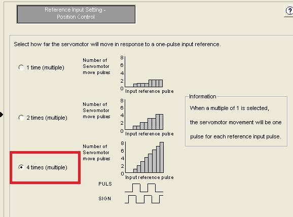
6 The Encoder should be automatically selected at this stage and you only need to click on "Apply" at the lower right have corner. The Encoder type will then be shown under the Encoder Selection button. Click "Control Mode Selection". Select "Position Control (pulse train reference)" from the drop down menu: Click "Apply". Click "Reference Input Setting "? Note: that the Control Mode setting will be highlighted in green, as you complete each section it will show green. Select "phase A + phase B" Click "Next". You will then need to select how far the servomotor will move in response to a one-pulse input. Select "4 times (multiple)" as shown below:
7


8 Click "Next". You will then be asked to Select the electronic gear setting method, select "Entr the electronic gear ratio directly" as shown below: Click "Next" You will then need to enter the gear ratio. Enter on top and on the bottom as shown in the image below: Enter 7for the Positioning Completed Width
9 Click "Apply" Reference Input settings will now be green.


10 Click "Motor Encoder Settings". Enter "8192" for the number of Encoder Pulses? This will yield Encoder counts per revolution of the motor as shown below: On the right side of the screen you will see the option to Set the dividing output according to the electronicgear ratio, as shown below. It is possible that you have gotten a motor with an absolute encoder if lead times are short and incremental encoders are not available. To use an absolute encoder the drive setting must be changed to use the encoder as an incremental encoder.: Click "Next". Select "Standard Setting":

11 Click "Apply".

12 You will be returned back to the Setup Wizard main screen, and the Encoder Settings section will now also be green. Click "Motor Stop Method" Selection. Set "Servo Off" to "0 - Stops motor by applying Dynamic Brake". Set "Overtravel" to "0 - Stops motor by applying Dynamic Brake". Set "G2 Alarm" to "0? Stops the motor by setting the speed reference to 0". If the Servo Motor has a Holding Brake you will need to select the "Use the Holding brake" option as shown below: Click "Apply". Click "IO Signal Settings", then click "Input Signal Settings". Disable "N-OT" by clicking in the "Always OFF" column as shown below. Disable "P-OT" by clicking in the "Always OFF" column as show below.

13 Click "OK". Click "Output Signal Settings".


14 For motors without Holding Brake the standard output settings is correct. For motors with a Holding Brake you must set "/COIN" and "/V-CMP" to "Always OFF". For motors with a Holding Brake you must also set "/BK" to "SO1? Output 1" as shown: below: Click "OK". You will then be returned to the IO Signal Settings screen, hit "Apply" to save the settings and then click "Save/Write". Check "Write with a backup file" this will save the current configuration and then write the current configuration fo the ServoPack: Click "Finish". Click "Yes" when prompted to complete the Setup Wizard. The ServoPack will now have an A941 Error? This indicates that a reset is required to apply the configuration changes.
15 To Reset the ServoPack you must click the "Software Reset" button in SigmaWin or remove power from the ServoPack. The Software Reset button is indicated below:

16 After pressing the "Software Reset" button you will receive a warning, simply click "Execute" to continue: Then click "Execute" at the next screen that pops up to confirm reset of the ServoPack. Every time the Drive is Reset you will normally get an error on the Centroid Control. Simply cycle ESTOPto clear the error message. Once the drive is reset you will have a "Motor Base Blocked - bb" message displayed on the ServoPack itself. This message means everything is OK. Test Run: We are now ready to perform a test run of the ServoPack and motor. This test run will be performed from the SigmaWin software using the Jog system. To enter Jog Mode select Jog from the Test Run menu: You will then see the Jog Operation Popup shown below:

17 Click "Edit" to change the JOG Speed. "10 RPM" is a good safe starting point. Release ESTOPon the Centroid Control. Click "Servo ON" to enable the ServoPack Motor Power.

18 The screen should then show "Servo ON" as shown below: You can now jog the motor by pressing and holding either the Forward or Reverse buttons If everything is workign correctly you should have smooth motion of the Servo Motor. Simple close the Test Jog popup to exit Jog Mode, the cycle ESTOP on the Centroid Control ServoPack Tuning: We are now ready to tune the Yaskawa ServoPack. There are two main options for tuning of the drive: "Tune Less Mode"? this is the default mode for the ServoPack, it obtains a stable response without adjustment. "Autotuning"? In this mode the ServoPack will attmept to tune itself to the dynamics of the system, saving the parameters for use after that. Note: Most ServoPack / Motor combinations seem to perform better once they have been Autotuned, so we will focus the rest of the time using that feature. The Tuning function is located under the Tuning menu: You will then see a safety warning about the use of Tuning? simply press "Execute" to continue.

19 You will then see the following Tuning Screen: Click "Execute"? this will begin the process to calculate the Moment of Inertia for the Motor system. You will then see the Condition Setting screen, click "Next". Click "Start" to transfer reference conditions to the ServoPack Click "Next". You will then see the Moment of Inertia calculation screen shown below:

20 Release ESTOPon the Centroid Control. Click "Servo ON" to apply power to the ServoPack Motor. Alternatingly click "Forward", then "Reverse " until the SigmaWin software will no longer allow you to press either one, signifying the completing of the movements. Click the "Next" button.

21 You will then see the following screen: Click the "Writing Results" button shown above to send the results to the ServoPack. Click "Finish". You will be prompted to Execute a ServoPack software Reset. Cycle ESTOPon the Centroid Control to clear any error messages generated by the ServoPack reset. You will then be returned to the Tuning screen. Click "No Reference Input" to ensure the correct mode during tuning, then click "Autotuning". You will then see the following Autotuning Set Conditions screen:

22

23 Set "Switching the moment of inertia" to "1: A moment of inertia is not presumed". Set "Mode Selection" to "2: For Positioning". Set "Mechanism Selection" to "2: Ballscrew mechanism". Ensure the Moving Range is set to "3.0" rotations, click "Next". You will receive another warning? click "Yes" to send parameters to the drive. You will then see the following Tuning Screen: Click "Servo ON". Click "Start Tuning", the ServoPack will then tune itself. Click "Finish" when tuning is complete. At this point the ServoPack and motor are tuned. Execture a Software Reset to be sure everything is back in good operation Centroid PID Configuration: We are now ready to start setting things on the Centroid side. Centroid Control Parameter 256 must be set to 2 to let the control know we are in Position Mode. When using Position Mode the Centroid PID values should all be zero'd out as shown below:
24 KP KI KV The Axis Encoder Counts on the Centroid must be set to the value that we used on the Yaskawa? in this case. To tune the control to any veriations in axis control you must perform a Position Mode Autotune. This is done by selecting <F5 Tune> from the PID menu. Braking Resistors: If the Yaskawa drive is wired to use an external braking resistor you must set Parameter 600 (Regenerative Resistor Capacity) on the Yaskawa to be equal to 20% of the wattage of the braking resistor. Document History Rev2 Created on by #000 Rev1 Created on by #358
TB267 (Rev4) - CNC11 Yaskawa Sigma5 Precision Mode Setup
 - CNC11 Yaskawa Sigma5 Precision Mode Setup") TB267 (Rev4) - CNC11 Yaskawa Sigma5 Precision Mode Setup Overview: This document will walk you through the process of configurating and tuning a Yaskawa Sigma V Servo Drive Pack and motor with a centroid
TB267 (Rev4) - CNC11 Yaskawa Sigma5 Precision Mode Setup Overview: This document will walk you through the process of configurating and tuning a Yaskawa Sigma V Servo Drive Pack and motor with a centroid
TB264 (Rev2) - Delta ASDA-A2 Precision Mode Setup With Optic Direct
 - Delta ASDA-A2 Precision Mode Setup With Optic Direct") TB264 (Rev2) - Delta ASDA-A2 Precision Mode Setup With Optic Direct Precision mode tuning and configuration of Delta ASDA2 servo drives and CNC11 v3.09+ software What you need: ASDA2 manual, Delta A2 Software,
TB264 (Rev2) - Delta ASDA-A2 Precision Mode Setup With Optic Direct Precision mode tuning and configuration of Delta ASDA2 servo drives and CNC11 v3.09+ software What you need: ASDA2 manual, Delta A2 Software,
MPiec Web User Interface
 TRAINING MPiec Web User Interface Class No. TRM010-Mpiec-WebUI Rev. A.01 Date: October 31, 2016 2015 YASKAWA America, Inc. YASKAWA.COM Instructor Introduction Matt Pelletier Product Training Engineer training@yaskawa.com
Product Demo Instructions. MP2600iec Demo Instructions: v03. Applicable Product: MP2600iec with MotionWorks IEC Pro
 Product Demo Instructions MP2600iec Demo Instructions: v03 Applicable Product: MP2600iec with MotionWorks IEC Pro Yaskawa Electric America 2121 Norman Drive South Waukegan, IL 60085 1-800-927-5292 Page
Axes Pairing Overview
 Axes Pairing Overview For the most part, this document pertains to all versions of CNC10 although some features discussed are available only in CNC10v 2.63 and above. For differences between your version
3200MK, 3300M/MK CNC Setup Utility
 3200MK, 3300M/MK CNC Setup Utility www.anilam.com P/N 70000373C - Contents Section 1 - Machine Setup Introduction... 1-1 Effectivity Notation... 1-1 Software Version Information... 1-1 Navigating through
Indra Works DS Tuning Procedure
 Indra Works DS Tuning Procedure Rexroth Indramat drives can be tuned in-house or in the field. The following procedures are written for a technician tuning a drive, in-house. Where an asterisk (*) appears,
SD DRIVE SERIES INSTALLATION MANUAL
 SD DRIVE SERIES INSTALLATION MANUAL Description: The SD Drives are an integral part of the Centroid CNC control solution. Packaged as a complete motor drive for AC brushless as well as DC brush motor control,
AC Servo Drives Engineering Tool SigmaWin+ ONLINE MANUAL. -7 Component MANUAL NO. SIEP S C
 AC Servo Drives Engineering Tool SigmaWin+ ONLINE MANUAL -7 Component MANUAL NO. SIEP S800001 48C Copyright 2014 YASKAWA ELECTRIC CORPORATION All rights reserved. No part of this publication may be reproduced,
Yaskawa Electric Engineering Corporation AC Servo Drives Engineering Tool EGSV Win ONLINE MANUAL EGSV3 Component
 Yaskawa Electric Engineering Corporation AC Servo Drives Engineering Tool EGSV Win ONLINE MANUAL EGSV3 Component MANUAL NO. ESI-M-002 1/38 Copyright c 2013 YASKAWA ELECTRIC ENGINEERING CORPORATION
TECHNICAL NOTE MOTION PRODUCT AND ENGINEERING GROUP
 Subject: Product: Engineer: MotionWorks+ Simple Template Program MP-940, MotionWorks+ v2.83 or later Michael J. Miller Who should read this document? Anyone is who is attempting to program an MP-940 Machine
AC Servo Drives Engineering Tool SigmaWin+ ONLINE MANUAL. Σ-V Component MANUAL NO. SIEP S F
 AC Servo Drives Engineering Tool SigmaWin+ ONLINE MANUAL Σ-V Component MANUAL NO. SIEP S800000 73F Copyright 2009 YASKAWA ELECTRIC CORPORATION All rights reserved. No part of this publication may be reproduced,
Quickstart Strategies for Commissioning and Optimization AX2000
 Quickstart Strategies for Commissioning and Optimization AX2000 Edition 06/00 Previous editions Edition Comments 06 / 00 First edition VGA is a registered trademark of International Business Machines Corp.
Demonstrating the Sigma II Indexer JUSP-NS600. Yaskawa part # DEMO4602
 Demonstrating the Sigma II Indexer JUSP-NS600 Yaskawa part # DEMO4602 1 Table of Contents 1) How to Demonstrate... Getting Started Program Table Selection and Execution Jog Speed Table Selection and Execution
GSK218M Milling Machine CNC System
 GSK218M Milling Machine CNC System GSK218M is widespread CNC system (matched with machining center and general milling machine) employed with 32-bit high performance CPU and super-large-scale programmable
For more information on these functions and others, please refer to the EDC User s Manual.
 EDC Handheld Device Guide BASIC FUNCTION When using the handheld controller, please set the dial switch to 0 on the front side of the panel of the EDC Controller. This will allow the user to have access
micromax R Getting Started Guide
 PN# 34-2114 Rev 1 04-25-2007 micromax R Introduction Introduction Thank you for purchasing Agile System s micromax R product. This guide covers how to install DPWin, connect, configure and tune a motor
SE Motion Products: Lexium23 Plus
 SE Motion Products: Lexium23 Plus Presenter Simone Gianotti Technical Marketing Specialist, Motion & Safety Solutions Course Objectives Upon completion of this course the participant should be able to:
AN Use Beckhoff TwinCAT System Manager to configure EtherCAT masters for control of ABB MicroFlex e150 servo drives
 Motion Control Products Application note Using TwinCAT with the MicroFlex e150 AN00203-002 Use Beckhoff TwinCAT System Manager to configure EtherCAT masters for control of ABB MicroFlex e150 servo drives
GuardLogix Controller to Kinetix 6000 Drive with Safe-Off using EtherNet/IP CompactBlock Guard I/O Module
 Safety Application Example GuardLogix Controller to Kinetix 6000 Drive with Safe-Off using EtherNet/IP CompactBlock Guard I/O Module Safety Rating: SIL3/Category 3 (also see SIL3/CAT4 section), according
3000M CNC Setup Utility Manual
 3000M CNC Setup Utility Manual www.anilam.com P/N 70000499F - Warranty Warranty ANILAM warrants its products to be free from defects in material and workmanship for one (1) year from date of installation.
Intelligent Operator Panel (IOP)
") Safety notes 1 Overview 2 SINAMICS SINAMICS G110D, SINAMICS G110M, SINAMICS G120, SINAMICS G120C, SINAMICS G120D Operating Instructions Installation 3 Wizards 4 Control 5 Menu 6 Options 7 Technical data
Safety notes 1 Overview 2 SINAMICS SINAMICS G110D, SINAMICS G110M, SINAMICS G120, SINAMICS G120C, SINAMICS G120D Operating Instructions Installation 3 Wizards 4 Control 5 Menu 6 Options 7 Technical data
G5-Series AC Servo Drives with General-purpose Pulse Train or Analog Inputs
 Refer to the Ordering Information. Specifications General Specifications Item Specifications Ambient operating temperature and humidity 0 to 55 C, % max. (with no condensation) Storage ambient temperature
Axidyne Multi-Axis System
 TOL-O-MATIC Axidyne Multi-Axis System Quick Reference Set Up Guide for Wiring, Tuning, Check Out For a FREE Tol-O-Matic Hat Please Complete the Attached Reply Card & Testing 3600-425_02 SSC Servo System
Apollo I Breakout Board User s Manual
 MACHMOTION Apollo I Breakout Board User s Manual 1/14/2012 Everything you need to know to set up and use your Apollo I Breakout Board. MachMotion Version 1.0.1 2 P a g e M a c h M o t i o n Copyright 2012,
Configuration of CMMT-AS- -EC/PN to run 3rd party motor
 Application Note Configuration of CMMT-AS- -EC/PN to run 3rd party motor This document describes how to configure and run 3 rd party motors in combination with CMMT-AS-..-EC/PN drive. CMMT-AS- -EC CMMT-AS-
New functionalities for LXM05 AC Servo drive Extension to product manual V1.00,
 New functionalities for LXM5 AC Servo drive Extension to product manual V1., 8.28 www.schneiderelectric.com Important information New functionalities for LXM5 Important information The new functionalities
TB048 (Rev1) - Laser Mapping Procedure (Software Versions Prior to 2.61)
 - Laser Mapping Procedure (Software Versions Prior to 2.61)") TB048 (Rev1) - Laser Mapping Procedure (Software Versions Prior to 2.61) Overview This document describes how to use a laser for ball screw mapping with CNC7 version 7.17 to CNC10 version 2.61. It assumes
TB048 (Rev1) - Laser Mapping Procedure (Software Versions Prior to 2.61) Overview This document describes how to use a laser for ball screw mapping with CNC7 version 7.17 to CNC10 version 2.61. It assumes
Three Axis CNC Driver Users Manual
 Three Axis CNC Driver Users Manual Revision 1.2 June 14. 2007 1 Content 1. GENERAL INFORMATION... 3 1.1. Scope... 3 1.2. General Description... 3 1.3. Features... 3 2. Descriptions of 3-AXIS CNC Board...
APPLICATION NOTE /20/02 Getting started using IPM240-5E with a brushless motor
 Problem: For new users of an intelligent drive, starting to implement a motion control application can be a quite complex task. You need to know how to hook-up the components of the motion system, to configure
imach III P3A and P3A-E CNC Control Pendant
 www.vistacnc.com - 1 - imach III P3A and P3A-E CNC Control Pendant www.vistacnc.com - 1 - imach III P3A Pendant Manual v. 3.4 www.vistacnc.com - 2 - PREFACE Any machine tool, including computer controlled
imach III P5A and P5A-E CNC Control Pendant
 www.vistacnc.com - 1 - imach III P5A and P5A-E CNC Control Pendant www.vistacnc.com - 1 - imach III P5A Pendant Manual v. 3.4.0 www.vistacnc.com - 2 - PREFACE Any machine tool, including computer controlled
5000M CNC Setup Utility Manual
 5000M CNC Setup Utility Manual www.anilam.com P/N 70000509D - Warranty Warranty ANILAM warrants its products to be free from defects in material and workmanship for one (1) year from date of installation.
S700 and S300 Motion Tasking Example
 S700 and S300 Motion Tasking Example Start the DriveGUI commissioning program The first Window is: To get started: Disable the drive (if it is enabled ) using the DIS button on the top toolbar. Set the
Apollo III INSTALLATION MANUAL
 Apollo III INSTALLATION MANUAL 2 P a g e 5/1/14 N0112 This manual covers the setup and configuration of the Apollo III motion controller connected to the control using Mach3. Formatting Overview: Menus,
Please read and understand this instruction manual thoroughly before using this product.
 Please read and understand this instruction manual thoroughly before using this product. For Mini-Z ASF 2.4GHz Series and dnano FX Series models I.C.S. Adaptor Set Manual Instruction Manual No. 82080 This
SINUMERIK 828D / 840D sl quick reference chart
 SINUMERIK 828D / 840D sl quick reference chart Jog functions 1. Power up with reference procedure (machine-dependent) Initial power up switch the main disconnect switch to on wait for the entire system
Apollo III User Manual - Mach3
 Apollo III User Manual - Mach3 WARNING! Improper installation of this motion controller can cause DEATH, INJURY or serious PROPERTY DAMAGE. Do not attempt to install this controller until thoroughly reading
FX3U-20SSC-H Quick start
 FX3U-20SSC-H Quick start Table of Contents: 1. Introduction 2. Components required for Setup 2.1. Hardware Requirements 2.1.1. Components 2.1.2. Setup 2.1.3. Wiring 2.2. Software Requirements 2.2.1. Components
NI 9512 C Series Modules and AKD Servo Drives
 GETTING STARTED NI 9512 C Series Modules and AKD Servo Drives Note If you are a new user of LabVIEW or are unfamiliar with LabVIEW, refer to the Getting Started with LabVIEW manual for information about
, USA, Canada, and Mexico
 Models 200 and 400 Introduction: This document describes the procedures to setup the Lean Automation Pack, LAP200 and LAP400 systems and how to use the sample application code provided. If you have any
Application Note. ESI File Usage. Applicable Products: Yaskawa SERVOPACKs with CANopen over EtherCAT
 1.1.1.1.1.1.1.1.1. Application Note ESI File Usage Applicable Products: Yaskawa SERVOPACKs with CANopen over EtherCAT Yaskawa America, Inc. Drives & Motion Division 2015 April 16, 2015 Page 1 of 6 Table
MRZJW3- SETUP154E. General-Purpose AC Servo Servo Configuration Software MODEL INSTALLATION GUIDE
 General-Purpose AC Servo Servo Configuration Software MODEL MRZJW3- SETUP154E INSTALLATION GUIDE Thank you for choosing the Mitsubishi general-purpose AC servo Servo Configuration Software. To optimize
APPLICATION NOTE. Title: SigmaLogic Example Code Example Manual. 1. Application Overview. Revision 2 February 21, 2018 Page 1 of 31
 1. Application Overview SigmaLogic is an EtherNet/IP Indexer that was designed to work seamlessly with the CompactLogix and ControlLogix PLCs from Allen Bradley. Yaskawa has created Add-On Instructions
G5-series AC Servo Drives with Built-in MECHATROLINK-II Communications. 0 to +55C, 90% RH max. (with no condensation)
") s with Built-in MECHATROLINK-II Communications R88D-KN@-ML2 Contents Ordering Information Specifications General Specifications Characteristics Servo Drives with Single-phase VAC Input Power Servo Drives
s with Built-in MECHATROLINK-II Communications R88D-KN@-ML2 Contents Ordering Information Specifications General Specifications Characteristics Servo Drives with Single-phase VAC Input Power Servo Drives
SMC-4000 Demo Program
 ENGINEERING PUBLICATION MOTION CONTROL DIVISION PRODUCT: SMC-4000 SUBJECT: DEMONSTRATING SMC-4000 CATEGORY: PRODUCT NOTE ENGINEER: KEVIN HULL DISTRIBUTION: ALL SMC-4000 Demo Program Page 1 of 1 The SMC4000
DeskCNC setup and operation manual
 DeskCNC setup and operation manual This document explains how to install, setup and cut foam shapes using DeskCNC 4 axis foam cutting software. The document will go through a step by step process of how
FlexWorks Version (Supporting FSP Amplifier Version 3.23)
") Flex Works Software User s Manual FlexWorks Version 3.0.1 (Supporting FSP Amplifier Version 3.23) FlexWorks User s Manual Copyright 2006 by YEA, Yaskawa Electric America, Inc. FlexWorks User s Manual
Flex Works Software User s Manual FlexWorks Version 3.0.1 (Supporting FSP Amplifier Version 3.23) FlexWorks User s Manual Copyright 2006 by YEA, Yaskawa Electric America, Inc. FlexWorks User s Manual
Motion Control Products Application note Dual encoder feedback control on motion drives
 Motion Control Products Application note Dual encoder feedback control on motion drives AN00262-001 Using standard functionality and hardware built into the motion drives we can accurately position loads
Unidrive M400 (Frame 1 to 4) Quick Start Guide
 Quick Start Guide") This guide is intended to provide basic information required in order to set-up a drive to run a motor. For more detailed installation information, please refer to the Unidrive M400 User Guide which is
This guide is intended to provide basic information required in order to set-up a drive to run a motor. For more detailed installation information, please refer to the Unidrive M400 User Guide which is
Converting an existing Bridgeport CNC to modern control with Mach4
 Converting an existing Bridgeport CNC to modern control with Mach4 This document will cover the construction and initial setup of all control components needed to retrofit an existing CNC knee mill with
Table of Contents. Part I USB Communication. Part II User Interface. Part III User Settings (Tab Control) DFS-1000 Dataview. 2 File Menu.
 DFS-1000 Dataview. 2 File Menu.") 2 Table of Contents Part I USB Communication 3 1 Important... Information 3 2 Connecting... Controller 3 Part II User Interface 4 1 Overview... 4 2 File Menu... 5 3 Options... Menu 6 4 Help Menu... 6 5
2 Table of Contents Part I USB Communication 3 1 Important... Information 3 2 Connecting... Controller 3 Part II User Interface 4 1 Overview... 4 2 File Menu... 5 3 Options... Menu 6 4 Help Menu... 6 5
Selecting Your Sigma II Indexer System
 Selecting Your Sigma II System Specify part number, the indexer add-on application module. Use the tables beginning on the following page to specify choice of indexer interface cables, mating connectors
SD17098IX Specifications Networked Stepper Driver & Indexer Revision 0.0
 The SD17098IX is a 170V 9.8amp stepper driver and indexer combination that communicates on a Network. The available networks, along with the corresponding AMCI part numbers, are shown in the following
Motor Objects. Methods
 Motor Objects Motor Objects Introduction A Motor object manages a single motor on a controller. It represents the physical connections between the motor, drive, and associated I/O. The Motor object contains
IEEM 215. Manufacturing Processes I Introduction to the ARIX CNC milling machine
 IEEM 215. Manufacturing Processes I Introduction to the ARIX CNC milling machine The image below is our ARIX Milling machine. The machine is controlled by the controller. The control panel has several
APPLICATION NOTE
 Problem: For new users of an intelligent drive, starting to implement a motion control application can be a quite complex task. You need to know how to hook-up the components of the motion system, to configure
Selecting Your Sigma II Indexer System
 Selecting Your Sigma II System Specify part number, the indexer add-on application module. Use the tables beginning on the following page to specify choice of indexer interface cables, mating connectors
M15 4 th AXIS UPGRADE
 M15 4 th AXIS UPGRADE M15 removed from mill. New parts to be added. The tools that will be needed. Also a drill and a #23 or 5/32 or.154 in. drill bit. 1. Remove the keyboard tray. 2. With the keyboard
How to use Digital key pad (option)
") Function of Digital key pad Monitoring of rotation speed (actual speed) and load factor, etc. Display detail of trip, and trip history. Trip reset by pressing and. Parameter setting, initialization, and
Function of Digital key pad Monitoring of rotation speed (actual speed) and load factor, etc. Display detail of trip, and trip history. Trip reset by pressing and. Parameter setting, initialization, and
Configuring Logosol CNC page 2. Setting up the machine limits and user units page 3. Setting up the Motion parameters page 4. I/O mapping page 7
 Configuring Logosol CNC page 2 Setting up the machine limits and user units page 3 Setting up the Motion parameters page 4 I/O mapping page 7 I/O setup page 9 Tools control page 11 Tool Life management
Date 18/05/17. Operation and maintenance instructions for driver configurator QSet
 Operation and maintenance instructions 28 1. General recommendations The recommendations regarding safe use in this document should be observed at all times. Some hazards can only be associated with the
SilverDust D2-IGF Datasheet
 Date: 16 October 2018 www.quicksilvercontrols.com SilverDust D2-IGF Datasheet Servo controller/driver for QuickSilver's NEMA 11, 17 and 23 frame, high torque, direct drive servomotors. This SilverDust
Simple Motion Control Connected Components Building Block. Quick Start
 Simple Motion Control Connected Components Building Block Quick Start Important User Information Solid state equipment has operational characteristics differing from those of electromechanical equipment.
Create MedicCoin Master Node Instruction Rev2
 Create MedicCoin Master Node Instruction Rev2 1. Download MedicCoin wallet using below link https://mediccoin.com/mediccoin-window.zip 2. Unzip/extract MedicCoin-Window.zip to C:\coins\MedicCoin folder.
Application Case. Application: Delta s AC Servo System on Robot Arms for CNC Machine Tools. Issued by Solution Center Date March 2013 Pages 5
 Case Application: Delta s AC Servo System on Robot Arms for CNC Machine Tools Issued by Solution Center Date March 2013 Pages 5 Applicable to Delta s AC Servo Drives and Motors Key words Servo System,
Tolomatic Motion Interface (TMI)
") NOTE: Throughout this manual information is color coded as it applies to products Tolomatic Motion Interface (TMI) Information that ONLY applies to Stepper Drives will be noted in grey box. ACS Stepper
NOTE: Throughout this manual information is color coded as it applies to products Tolomatic Motion Interface (TMI) Information that ONLY applies to Stepper Drives will be noted in grey box. ACS Stepper
Please read and understand this instruction manual thoroughly before using this product.
 Please read and understand this instruction manual thoroughly before using this product. For Mini-Z ASF 2.4GHz Series and dnano FX Series models I.C.S. USB Adaptor Set Manual Instruction Manual No. 82080
Mach3 USB Motion Card Installation Manual
 Mach3 USB Motion Card Installation Manual Features: Fully supporting all Mach3 versions, including the Mach3 R3.043.066 version. Supporting Windows series, including Windows2000/XP/Vista/Win7/Win8/Win10.
Using SimplexMotion integrated motors for simple standalone applications
 Using SimplexMotion integrated motors for simple standalone applications This document describes how to use the SimplexMotion integrated motor units for simple motion tasks where the motor is manually
Basic Drive Programming PowerFlex 755 Basic Start Up
 Basic Drive Programming PowerFlex 755 Basic Start Up PowerFlex 755 Basic Start Up for Speed Controlled Applications Contents Before you begin... 4 Tools... 4 About this lab... 4 About the Demo... 4 Lab
DCS800 Control Panel operation
 420 DCS800 Control Panel operation Chapter overview This chapter describes the handling of the DCS800 Control Panel. Start-up The commissioning configures the drive and sets parameters that define how
A Axis M-Functions Level 1 A Axis Standard A Axis SMT Level 2. Each console includes the following:
 Hardware List The 3000M Crusader II Upgrade system has been custom configured to provide the necessary hardware required for installation on your machine. Verify that you have received all the correct
Ether-Mach Mach3 Plugin Guide
 Ether-Mach Mach3 Plugin Guide Ethernet Motion Controller for Artsoft's Mach3 CNC. Features Connects over a dedicated 100 Mbps Ethernet connection. Smooth motion on 6 coordinated axes plus a spindle motor.
Mitsubishi General-Purpose AC Servo Sales and Service
 Mitsubishi General-Purpose AC Servo Sales and Service No. 10-26E Transition to Made-to-order Production for General-purpose AC Servo MR-C Series Thank you for your continued patronage of the Mitsubishi
Galil Motion Control. DMC - 42x0. Datasheet
 Galil Motion Control DMC - 42x0 Datasheet Product Description The DMC-42x0 is part of Galil s highest performance, stand- alone motion controller Accellera family. Similar to the rest of Galil s latest
 Supplementary Manual for the Driver Configuration 1. Please install the operation program to your PC from the attached disk or Ye Li website. Ye Li icon will appear after the installation process.
SERVOSTAR (S601...S620) Quickstart Guide. Version
 Quickstart Guide. Version") SERVOSTAR 601...620 (S601...S620) Quickstart Guide Version 12.2014 Keep all manuals as a product component during the life span of the product. Pass all manuals to future users/owners of the product. Preparation
SERVOSTAR 601...620 (S601...S620) Quickstart Guide Version 12.2014 Keep all manuals as a product component during the life span of the product. Pass all manuals to future users/owners of the product. Preparation
Upgrade Information of MPE720 Version 7.30
 Upgrade Information of MPE720 Version 7.30 1. Added and Improved Functions 1.1 Version 7.30 Upgrade Information Items added and features improved from MPE720 version 7.29 to version 7.30 are as follows.
Tri Tr t i e t x e Expert Softwar Softwar O verview Overview
 Tritex Expert Software Overview Free download available at www.exlar.com/software Getting Started To get started, select File New Application Select Drive Series, Option Board, and Application templates,
WL-400 Milling Machine Operator s Manual
 WL-400 Milling Machine Operator s Manual. www.levil.com techsupport@levil.com (407) 542-3971 Introduction This manual covers the safety, usage and maintenance of the tabletops CNC milling machines manufactured
Upgrade Information of MPE720 Version 6.08
 Upgrade Information of MPE720 Version 6.08 1 Added and Improved Functions 1.1 Version 6.08 Upgrade Information Items added and features improved from MPE720 version 6.07 to version 6.08 are as follows.
Please read and understand this instruction manual thoroughly before using this product.
 Please read and understand this instruction manual thoroughly before using this product. For Mini-Z ASF 2.4GHz Series and dnano FX Series models I.C.S. USB Adaptor Set Manual Instruction Manual No. 82080
Command Manual. -7-Series AC Servo Drive MECHATROLINK-III Communications Standard Servo Profile. MECHATROLINK-III Communication Settings
 -7-Series AC Servo Drive MECHATROLINK-III Communications Standard Servo Profile Command Manual MECHATROLINK-III Communication Settings Command Format Main Commands Subcommands Operation Sequence Function/Command
Software designed to work seamlessly with your CNC Masters machine. Made to work with Windows PC. Works with standard USB
 Software designed to work seamlessly with your CNC Masters machine Made to work with Windows PC Works with standard USB Clutter free interface. The software is engineered for the machine so you don t have
Data Sheet MEM 16. Absolute Encoder Multiturn
 Absolute Encoder Multiturn Features Resolution: Singleturn: up to 8,192 (13 Bit) steps per revolution Multiturn: up to 4,294,967,296 (32 Bit) revolutions Interface: SSI (synchron serial interface) or BiSS
SERVOSTAR 400 (S400) Quickstart Guide. Version
 Quickstart Guide. Version") SERVOSTAR 400 (S400) Quickstart Guide Version 12.2014 Keep all manuals as a product component during the life span of the product. Pass all manuals to future users/owners of the product. Preparation The
SERVOSTAR 400 (S400) Quickstart Guide Version 12.2014 Keep all manuals as a product component during the life span of the product. Pass all manuals to future users/owners of the product. Preparation The
Troubleshooting Err27.4
 Troubleshooting Err27.4 2014/1/23 Motor Business Division Appliances Company Panasonic Corporation Err27.4 Command Error When Err27.4 occurs on correct parameter setting, there is a problem inside command
Commercial and Residential Turntables. Motion Control User Manual Model MC-2
 Commercial and Residential Turntables Motion Control User Manual Model MC-2 Introduction The control system for the Carousel Turntables offers four modes of operation: 1. Manual 2. Camera 3. Preset 4.
Instruction Manual for Teaching Device
 Shenzhen Han`s Motor S&T Co.,Ltd Instruction Manual for Teaching Device V 3.3 2017-07-19 Directory 1 Introduction... 1 2 Installation instruction...1 2.1 DCS and teaching device installation... 1 3 Software
PC Focus Control Operator's Guide
 PC Focus Control Operator's Guide Copyright 2008 JMI Telescopes Jim's Mobile, Incorporated 8550 West 14th Avenue Lakewood, CO 80215 U.S.A. Phone (303) 233-5353 Fax (303) 233-5359 Order Line (800) 247-0304
Preface. GSK983Ma User Manual divides into three parts, that is, Programming, Operation and Appendix.
 This user manual describes all proceedings concerning the operations of this CNC system in detail as much as possible. However, it is impractical to give particular descriptions for all unnecessary or
General. Specifications. F3NC96-0N Positioning Module (with MECHATROLINK-II Interface) GS 34M6H60-02E. General. Specification
 GS 34M6H60-02E. General. Specification") General Specifications GS 34M6H60-02E F3NC96-0N Positioning Module (with MECHATROLINK-II Interface) General This positioning module is to be installed on the base unit of a FA M3 range free controller
General Specifications GS 34M6H60-02E F3NC96-0N Positioning Module (with MECHATROLINK-II Interface) General This positioning module is to be installed on the base unit of a FA M3 range free controller
KNC-SRV-FD332S Servo Driver
 FEATURES 88-126VAC Single Phase Input 750-1000 Watt Power Range Position, Speed, and Torque Control Communication Ports: RS232 and RS485 Communication Protocol: MODBUS 2500PPR Incremental Communication
SINAMICS V-ASSISTANT Online Help SINAMICS. SINAMICS V90 SINAMICS V-ASSISTANT Online Help. Preface. Safety instructions 1 SINAMICS V-ASSISTANT 2
 Preface Safety instructions 1 SINAMICS SINAMICS V90 SINAMICS V-ASSISTANT Online Help SINAMICS V-ASSISTANT 2 User interface 3 Task navigation 4 Operating Manual 02/2015 A5E32187373-003 Legal information
Quick start commissioning guide. Unidrive SP. Positioning Solution. Part number : 3773 en / c
 Quick start commissioning guide Unidrive SP Positioning Solution Part number : 3773 en - 27. / c Incorrect operational procedures may cause serious body injuries or material damages. This guide may be
Release Notes for MPiec controller firmware
 Release Notes for MPiec controller firmware Release 2.1.0 Build 229 Yaskawa America, Inc. January 23, 2012 1. New Features Number Summary Release Notes 5434 MC_Reset should work on axes not discovered
MRZJW3-SETUP221E INSTALLATION GUIDE. MR Configurator MODEL
 MR Configurator MODEL MRZJW3-SETUP221E INSTALLATION GUIDE Thank you for choosing the MELSOFT MR Configurator. To optimize the use of the MR Configurator, please read over this Installation Guide and the
3 CU240E-2 6SL3244-0BB12-1BA1 3 CU240E-2 DP 6SL3244-0BB12-1PA1. RS485/USS 6 3 (opt. per 2 DI) 3 CU240E-2 F 6SL3244-0BB13-1BA1
 3 CU240E-2 F 6SL3244-0BB13-1BA1") Control Units CU240B-2, CU240E-2 Overview Safety Integrated functions The basic version of the CU240E-2 series (CU240E-2 and CU240E-2 DP) includes the safety function Safe Torque Off (STO) (certified according
Control Units CU240B-2, CU240E-2 Overview Safety Integrated functions The basic version of the CU240E-2 series (CU240E-2 and CU240E-2 DP) includes the safety function Safe Torque Off (STO) (certified according
Stepper Drive Setup Guide
 MACHMOTION Stepper Drive Setup Guide 1/21/2011 Everything you need to know to connect your stepper motors to the MachMotion stepper drives. MachMotion Version 1.0.1 2 P a g e Copyright 2011, MachMotion.com