User Manual. ParticleScan CR ParticleScan Pro
|
|
|
- Victor McKenzie
- 6 years ago
- Views:
Transcription


1 User Manual ParticleScan CR ParticleScan Pro
2 The IQAir Group reserves the right to change specifications contained in this document at any time and without prior notice. Copyright The IQAir Group All rights reserved. IQAir is a registered trademark of The IQAir Group. ParticleScan is a trademark of The IQAir Group.
3 Important Safety Information Important Safety Information Class 1 Laser Product This product incorporates a Class 1 laser diode based sensor as defined in 21 CFR, Subchapter J, of the Health and Safety Act of 1998 and applies when the instrument is used under normal operating conditions and during maintenance procedures. Service procedures performed on the sensor can result in exposure to invisible radiation. Service The laser diode based sensor inside this instrument carries a warning label as shown below: -WARNING- INVISIBLE LASER RADIATION WHEN OPEN AVOID EXPOSURE TO BEAM Warning Do not attempt to sample reactive gases (such as hydrogen or oxygen) with the particle counter. Reactive gases create an explosion hazard within the counter. Water, solvents, or other liquids of any type should never be allowed to enter the instrument.
4 Table of Contents page Important Safety Instructions Chapter 1 About Particle Counting How do Particle Counters Work? The Two ParticleScan Models Data Logging Options 6 Chapter 2 The ParticleScan Kit Unpacking and Initial Inspection Packing List 7 Chapter 3 Getting to Know the ParticleScan The ParticleScan Unit ParticleScan Features 9 Chapter 4 Taking Measurements with the ParticleScan Preparing the ParticleScan for Use Switching the ParticleScan On and Off Sampling Particles Taking Samples at Different Size Channels 10 Chapter 5 Adjusting Settings in the Menu Location Menu [Loc] Data Logging Menu [Log] Delete Data Menu [data] Full Memory Menu [FULL] Concentration Units Menu [Con] Sample Time Menu [SAti] Sample Repeat Menu [SAr] Geiger Counter Menu [GEIG] Alarm Menu [A] Time Menu [t] Date Menu [MM:DD:YYYY] Auto Timer Menu [auto] IP Menu [IP] Remote Monitoring Menu [InEt] 13 Chapter 6 Maintenance of the ParticleScan The Battery Low Battery Indicator Recharging the Battery Replaceeid1[UtV]T [l
5 Table of Contents Table of Contents page Chapter 7 Computer Connectivity Features Computer Connectivity Options Via a Network Via a Crossover Connection Via USB USB Driver Installation ParticleScan USB Software for PC Installation Starting the ParticleScan USB Software for PC Accessing the ParticleScan via the Web Browser The ParticleScan Control Window Start/Stop Measurements Sample Time Sample Repeat Measurement Units Count Type ParticleScan Display On/Off Setting the Time & Date Using the Auto Timer Scheduling Regular Measurements Data Logging Checklist Before Data Logging Data Logging to Computer Data Logging to ParticleScan Memory Full Memory Options Viewing Logged Data Printing Logged Data Saving Logged Data to a CSV File Importing a ParticleScan Data File into Excel 26 Chapter 8 Troubleshooting Symptom, Cause and Corrective Action 28 Chapter 9 Technical Specifications for ParticleScan Pro and CR Technical Specifications 29
6 Chapter 1 About Particle Counting Chapter 1 About Particle Counting 1.1 How Do Particle Counters Work? Laser particle counters use a laser diode light source and collection optics for particle detection. Particles scatter the light from the laser diode beam in the direction of the collection optics. The collection optics focus the light onto a photo diode that converts the bursts of light into electrical impulses. The pulse height is proportional to the particle size. Impulses are counted and their intensity is measured for particle sizing. The results are then displayed digitally for the specific size channel(s) and set measurement unit. 1.2 The Two ParticleScan Models The six-channel ParticleScan handheld particle counters are available in two configurations: ParticleScan Pro This model is designed for indoor air quality use, featuring a cfm sampling rate. The flow rate of cfm of the ParticleScan Pro is more suitable for environments with normal to high particle counts since the lower flow rate and smaller sampling diameter allow more accurate counting of elevated particle concentrations. ParticleScan CR This model is designed for cleanroom use, featuring a 0.1 cfm sampling rate and a HEPA filter for the exhaust air. The higher flow rate of the ParticleScan CR permits statistically significant results even if the particle concentration is low and the measurement time is short. 1.3 Data Logging Options ParticleScan Pro and ParticleScan CR handheld counters allow the logging (recording) of measurement data onto the ParticleScan s internal memory from where it can be downloaded at a later time to a computer via the ParticleScan Utility Software or a web browser. When the ParticleScan is connected to a computer or network, measurement data can also be logged in real time to the computer via the ParticleScan USB Utility Software. In both cases, the data can be viewed and saved to a text file that can be easily opened and formatted in any common spreadsheet program. Logged data can also be printed directly from the logging window to a printer. A printout of particle counting results can be used as a record whenever documentation of room cleanliness is required, as in Fed-Std-209E cleanroom certification. A permanent record is also useful when tracking the particle concentration trend at a workstation or other remote location. 6

7 Chapter 2 The ParticleScan Kit Chapter 2 The ParticleScan Kit 2.1 Unpacking and Initial Inspection Each ParticleScan device has been thoroughly inspected and tested by the manufacturer and is ready for use. Prior to use, please read this instruction manual. Upon receipt, inspect the shipping carton for damage. If the carton is damaged, notify the carrier and dealer and save the carton for carrier inspection. Note: You may wish to keep the outer carton for safe shipment when you send the ParticleScan for calibration. Always store and ship the ParticleScan in the carrying case. 2.2 Packing List Open the two latches of the carrying case and inspect the kit for completeness. Also check visually for broken parts, scratches, dents or other damage. Your ParticleScan kit should consist of the following items: ParticleScan device (with red protection cap on intake nozzle) Protective carrying case Isokinetic probe with tubing Power adaptor Purge filter with tubing Network cable (Ethernet, Cat. 5) Crossover adapter (Ethernet, Cat 5) USB cable ParticleScan CD with ParticleScan USB Utility Software, USB drivers Java Runtime, Excel data import sheet, ParticleScan pdf-manual User manual Calibration certificate Warranty registration card 7
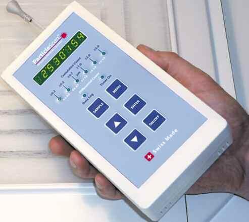
 Charging LEDs Power socket USB port (Mini-B) Display Calibration date sticker Particle Size Indicators")
8 Chapter 3 Getting to Know the ParticleScan Chapter 3 Getting to Know the ParticleScan 3.1 The ParticleScan Unit Isokinetic probe Tygon tube Intake nozzle Ethernet port (RJ-45) Charging LEDs Power socket USB port (Mini-B) Display Calibration date sticker Particle Size Indicators Differential Count Ranges Auto Timer Indicator Data Log Indicator SAMPLE Key UP Key ENTER Key DOWN Key ON/OFF Key Press and hold 2 sec. Cumulative Count Ranges Low Battery Indicator When both Data Log and Auto Timer flash MENU Button Press to display one of 13 menus: 1. Location Menu [Loc] 2. Data Logging Menu [Log] 3. Delete Data Menu [data] 4. Full Memory Menu [FULL] 5. Concentration Units Menu [Con] 6. Sample Time Menu [SAti] 7. Sample Repeat Menu [SAr] 8. Geiger Counter Menu [Geig] 9. Alarm Menu [A] 10. Timer Menu [t] 11. Date Menu [MM.DD.YYYY] 12. Auto Timer Menu [auto] 13. IP Menu [IP] 14. Remote Monitoring Menu [InEt] 8
9 Chapter 3 Getting to Know the ParticleScan 3.2 ParticleScan Features Isokinetic probe The isokinetic probe with the Tygon tube piece allows uniform low turbulence sampling of ambient air. It is also necessary for proportional sampling of particles of all sizes. Intake nozzle The intake nozzle is covered during shipping with a protective red plastic cap, which is designed to keep small objects from entering into the sampling chamber. The cap must be removed prior to taking a sample to prevent possible damage to the internal pump. Display When the device is off and not connected to the charger, the display will also be off. If the device is off and connected to the charger, it will show [charging] or [charged]. When the unit is sampling, the particle concentration measured will be displayed. The displayed concentration can be shown for one particle size range at a time (see Particle Size Indicators). When the Menu key is pressed, the display will show the user settings. Particle Size Indicators The particle size indicators show which particle size range is currently displayed. When the Alarm is set and the set particle concentration threshold is exceeded, the appropriate particle size indicator will flash and a beep will sound. Cumulative Count Ranges There are six cumulative size channels to select from: 0.3 / 0.5 / 0.7 / 1.0 / 2.0 / 5.0 microns. When a cumulative size channel is selected, the ParticleScan will count particles which are equal to and larger than the selected size channel. Differential Count Ranges There are five differential size channels to select from: / / / / microns. When a differential size channel is selected, the ParticleScan will count the particles whose size lies between the selected two size channels. Data Log Indicator This indicator lights up when data logging has been turned on. Whenever a measurement is taken, it will be logged to the ParticleScan s internal memory. Timer On Indicator This indicator lights up when the auto timer is actively set. The Auto Timer is a feature that allows the ParticleScan to take automatic measurements based on a timer schedule. The Auto Timer schedule is set via the ParticleScan USB Utility Software or the web browser interface. Low Battery Indicator When the battery is running low, both the Data Log Indicator and the Timer On Indicator will flash. The unit can operate for another 5 10 minutes from the time the Low Battery Indicator comes on. ON/OFF Key Press and hold for 2 seconds to turn the device on or off. SAMPLE Key Press once when the device is on to start a measurement. Press again to stop a measurement. UP/DOWN Keys Use during a measurement to select size channel displayed. It is also used to change a menu setting. MENU Key Press 1 to 14 times to display one of 14 user menus. ENTER Key Press and hold for 2 seconds when in a menu to make a menu item changeable. Press once in certain menus to progress. Press and hold for 2 seconds to save changes in a menu. 9
10 Chapter 4 Taking Measurements with the ParticleScan Chapter 4 Taking Measurements with the ParticleScan 4.1 Preparing the ParticleScan for Use To prepare your ParticleScan for use, simply follow these steps: 1. Remove the red protective cap from the intake nozzle. 2. Take the isokinetic probe and attach it with the tubing end to the intake nozzle. 4.2 Switching the ParticleScan On and Off 1. To switch the ParticleScan on, press and hold down the ON/OFF key for 2 seconds. When the device is turned on, it will sound a short beep and show [STANDBY] on the display. 2. To turn off the device, press and hold down the ON/OFF key for 2 seconds. When the ParticleScan turns off, it will sound a short beep and the display will extinguish or show [Charging] when it is connected to the power adapter. 4.3 Sampling Particles 1. To take a measurement, turn the ParticleScan on and press the SAMPLE key. The display will count down while the pump gathers the first air sample and then displays the first measurement. There will be a delay of a few seconds until the countdown starts, during which the ParticleScan performs a routine check. The number in the display represents the number of particles calculated to be present per cubic foot, liter or cubic meter (1000 liters) of air, depending on the concentration unit selected (see Chapter 5.5). 2. The display of the ParticleScan will update in regular intervals, as selected in the Sample Time Menu. The default setting is 6 seconds (see Chapter 5.6). 3. To stop taking measurements, press the SAMPLE key once. The last measurement result is now frozen on the display. 4.4 Taking Samples at Different Size Channels The ParticleScan features six size channels which allows the user to take cumulative counts for six different particle size ranges and differential counts for five different size ranges. 1. When the ParticleScan is first switched on, it will display the particle concentration per cubic foot (cu. ft.) of air for the default Cumulative Count Range (i.e. 0.3µm). 2. To change the size channel to the next particle size range, simply press the UP key once. The Size Range Indicator LED will shift from 0.3 to Repeated pressing of the UP key will scroll through all the different size ranges, first the Cumulative Count Ranges, then the Differential Count Ranges. To reach the required count range, simply scroll through all the count ranges until the desired Particle Size Indicator is lit. 10
11 Chapter 5 Adjusting Settings in the Menu Chapter 5 Adjusting Settings in the Menu The ParticleScan Pro/CR has 14 menus which allow the user to set a range of parameters. To access these menus, press the MENU key one to 14 times. To fast exit a menu at any time and get back to the measurement screen, you may press the SAMPLE key at any time. 5.1 Location Menu [Loc] The Location Menu allows the user to assign a location number from to any data that is logged. To change the location number, press the MENU key once until the display shows [Loc]. Press and hold the ENTER key for two seconds until the location number starts to flash. Then use the UP or DOWN key, to select the desired location number. To confirm the selection, press and hold the ENTER key for two seconds, until the location number stops flashing. 5.2 Data Logging Menu [Log] The Data Logging Menu allows the user to log data to the ParticleScan s internal memory. A user can set this function to be on or off. Whether data logging is currently on or off is indicated by the status of the Data Log indicator. To turn the data logging on or off, press the MENU key until the display shows [Log]. Press and hold the ENTER key for two seconds until [on] or [off] selection starts to flash. Use the UP or DOWN key to select the desired setting. Confirm the selection by pressing and holding the ENTER key for two seconds, until the selection stops flashing. 5.3 Delete Data Menu [data] The Delete Data Menu shows how many data points have been logged to the ParticleScan memory and allows to erase the logged data. The ParticleScan can log a maximum of 14,336 data points. To view the number of data points logged to the ParticleScan internal memory, press the MENU key until the display shows [data]. To delete the logged data, press and hold the ENTER key for two seconds until [del_data] flashes on the display. Press and hold the ENTER key for two seconds to confirm the deletion of all logged data. After the deletion of logged data the display will show [data 0]. 5.4 Full Memory Menu [FULL] The Full Memory Menu allows the user to select what should happen when the ParticleScan s data log memory is full. [FULLstop] means that once the maximum number of data points have been logged, data logging will stop. [FULLcycl] means that once the maximum number of data points has been logged, newly logged data will overwrite the oldest ParticleScan data logged. To change the Full Memory Setting, press and hold the ENTER key for two seconds until the [stop] or [cycl] selection starts to flash. Use the UP or DOWN key to select the desired setting. Confirm your selection by pressing and holding the ENTER key for two seconds until the selection stops flashing. 5.5 Concentration Units Menu [Con] The Concentration Units Menu allows the user to select whether the particle concentration is displayed in particles per cubic foot [Con CF], particles per liter [Con Lit] or particles per cubic meter (1000 liter) [Con1000L]. To change the concentration units, press and hold the ENTER key for two seconds until the [CF], [1000L] or [L] selection starts to flash. Use the UP or DOWN key to select the desired setting. Confirm your selection by pressing and holding the ENTER key for two seconds until the selection stops flashing. 11
12 Chapter 5 Adjusting Settings in the Menu 5.6 Sample Time Menu [SAti] The Sample Time Menu allows the user to select the sampling period (in terms of seconds) for particle sampling. The default setting is 6 seconds, which means that the ParticleScan will sample and display a new particle concentration measurement after 6 seconds.the minimum time period that can be set is 1 second and the maximum update period is 600 seconds (10 minutes). To change the sample time period, press and hold the ENTER key for two seconds until the currently set time period starts to flash. Use the UP or DOWN key to select the desired setting. Confirm your selection by pressing and holding the ENTER key for two seconds until the selection stops flashing. 5.7 Sample Repeat Menu [SAr] The Sample Repeat Menu allows the user to have the ParticleScan take just one sample [OncE] and hold the result or take continuous samples [Cont] until the sampling is stopped. The default setting is continuous. To change the Sample Repeat setting, press and hold the ENTER key for two seconds until the current setting starts to flash. Use the UP or DOWN key to select the desired setting. Confirm your selection by pressing and holding the ENTER key for two seconds until the selection stops flashing. 5.8 Geiger Counter Menu [GEIG] The Geiger Counter function enables the ParticleScan to emit an audible signal at intervals which are proportionate to the number of particles ( 0.3 µm) that are detected in a period of one second. The Geiger Counter Menu allows the user to choose from 10 sensitivity levels. The most sensitive setting is 1, which means that for each particle counted in a period of one second, the ParticleScan will generate one beep. The least sensitive setting is 10, which means that for every 500 particles counted in a one-second period, one beep will be generated. To change the Geiger Counter setting, press the Menu key until you reach the Menu display starting with [GEIG]. Press and hold the ENTER key for two seconds until the current setting starts to flash. Use the UP or DOWN key to select the desired setting. [OFF] means that the Geiger Counter function is disabled. 1 to 10 represent the available sensitivity settings (see table). Use the UP or DOWN key to select the desired setting. Confirm your selection by pressing and holding the ENTER key for two seconds until the selection stops flashing. Setting Note: Whereas the ParticleScan display updates particle concentration after 6 seconds (default), the Geiger Counter issues a beep based on the number of particles sampled in one second. Due to the shorter sampling period, the Geiger Counter reacts more quickly to changes in particle concentrations than the display. OFF One beep per x particles N/A Alarm Menu [A] The Alarm Menu allows the user to set audio alarm thresholds for every one of the six cumulative ( 0.3, 0.5, 0.7, 1.0, 2.0, 5.0 microns) and five differential ( , , , , microns) size channels. When an alarm threshold is exceeded, a beep alarm will sound and the appropriate channel size LED will flash. To set an alarm threshold for a channel, use the UP or DOWN key to select the size channel for which you would like to activate the alarm. Then press the Menu key until you reach the Menu display starting with [A] for Alarm. Press and hold the ENTER key for two seconds until [A ] appears. Use the UP or DOWN key to enter the first digit and/or press the ENTER key to move one digit to the right. Once the desired threshold is entered, press and hold the ENTER key for 2 seconds to confirm. To turn off an alarm threshold, select the appropriate size channel LED with the UP or DOWN key, press the MENU key until you reach the Menu starting with [A], press and hold the ENTER key for two seconds until the display shows [A ], with the first zero flashing. Press and hold the ENTER key for two seconds until the zero stops flashing and switches to [A OFF]. Your alarm threshold has now been turned off. 12
13 Chapter 5 Adjusting Settings in the Menu 5.10 Time Menu [t] The Time Menu allows the user to set the current time inside the ParticleScan. The ParticleScan uses a 24 hour clock format. The internal clock is used to time stamp logged measurements. It is also used for the automatic timer function. To set the time, press the MENU key until the display menu that starts with [t] is shown. Press and hold the ENTER key for two seconds until the hour block flashes. Use the UP or DOWN key to set the hours. Press the ENTER key to advance to the minutes. Use the UP or DOWN key to set the minutes. Press the ENTER key to advance to the seconds. Use the UP or DOWN key to set the seconds. Press and hold the ENTER key for two seconds until the flashing stops to save the selection Date Menu [MM:DD:YYYY] The Date Menu allows the user to set the current date inside the ParticleScan. The date format used is MM:DD:YYYY. This date is used to date stamp logged measurements. It is also used for the automatic timer function. To set the date, press the MENU key until [MM DD YYYY] is shown on the display. Press and hold the ENTER key for two seconds until the month block starts flashing. Use the UP or DOWN key to set the current month. Press the ENTER key to advance to the days. Use the UP or DOWN key to set the day. Press the ENTER key to advance to the year. Use the UP or DOWN key to set the year. Press and hold the ENTER key for two seconds until the flashing stops to save the selection Auto Timer Menu [auto] The Auto Timer Menu allows the user to activate or inactivate a timer program that has been set via the ParticleScan web browser interface (see Chapter 7.7). The auto timer allows the ParticleScan to turn itself on and off to take measurements at regular intervals. This is useful to collect regular particle samples over long periods, without having to sample all the time. This is desirable for permanent sampling applications, in order to reduce the wear on the sampling pump and other components. It also can be useful to reduce sampling noise in noise-sensitive environments IP Menu [IP] The IP Menu allows the user to activate and deactivate the network port (RJ-45) and assign an IP address to the ParticleScan on the network. The IP address is a number with which the ParticleScan is identified on a network. When the IP number is entered into a web browser such as Internet Explorer, the ParticleScan can be accessed via the network. The IP Menu has three main settings: IP OFF, DHCP and STATIC. The default setting of the IP Menu is IP OFF, which means that the RJ-45 port of the ParticleScan is inactive. NOTE: Data transfer via the USB port requires the IP Menu selection to be set to [IP OFF]. To activate DHCP, press the MENU key until the IP Menu [IP OFF] appears, press the ENTER key for three seconds until [IP OFF] starts to flash. Then press the ARROW DOWN key once. [DHCP] will appear flashing on the display. If the ENTER key is pressed, the DHCP mode is activated. To view the current IP address that has been assigned to your ParticleScan by a network router, connect your ParticleScan to a network with a network cable and ensure that DHCP is selected in the IP Menu. The IP Menu should now show the IP address assigned to your ParticleScan by intermittently displaying [DCHP], [IP xxx xxx ] and [ xxx xxx]. The x stands for numbers. The IP address consists of four blocks separated by a period. The first two blocks have the IP in front. Blocks three and four do not. A typical IP address could look like this on the ParticleScan display: [IP ]. In this example, the IP address would be It is this set of numbers together with the periods must be entered into the address field of the web browser. When the IP address is flashing on the display, this means the ParticleScan is not receiving an IP address. This could be due to a problem with the physical connection to the network or a problem with the DHCP server. Note: If the ParticleScan was disconnected from the network, it can take up to 3 minutes for the ParticleScan to be reassigned an IP address by the network router. In some network environments, it may be desirable to manually assign a specific, fixed IP address, commonly referred to a a static IP address. To set a static IP address, go to the IP menu, press the ENTER key for two seconds until the display starts flashing. Then press the ARROW UP or DOWN key until [STATIC] flashes on the display. Press the ENTER key for two seconds until a constant [-STATIC] appears. Now you can adjust the IP address [-IP Addr], the subnet mask [-Subnet] and the gateway [-Gate], by pressing an ARROW key to reach the item to be modified, followed by pressing and holding the ENTER key. The ARROW and ENTER keys serve to modify the IP address, subnet mask and the gateway. 13
14 Chapter 6 Maintenance of the ParticleScan 5.14 Remote Monitoring Menu [InEt off] (Beta-Feature) Please visit to find out more about this beta-feature. Important Note: Changing [InEt off] to [InEt on] disables all normal functions. These normal functions can be enabled again at any time by selecting [InEt off]. Chapter 6 Maintenance of the ParticleScan 6.1 The Battery Your ParticleScan is equipped with a internal Ni-MH (Nickel-Metal Hydride) rechargeable battery pack. Fully charged, the ParticleScan Pro will run continuously for up to five hours and the ParticleScan CR will run continuously for up to four hours. Note: For maximum battery life, IP OFF should be selected in the IP Menu (see Chapter 5.13) Low Battery Indicator When the battery is running low, both the Data Log Indicator and the Timer On Indicator will flash simultaneously. The unit can operate for another 5-10 minutes from the moment the Low Battery Indicator comes on Recharging the Battery To recharge the internal battery pack of the ParticleScan, simply connect the supplied power adaptor/charger to a power outlet and the round connector to the power socket of the ParticleScan. It takes about 3 hours to fully recharge the internal battery pack. When the unit is turned off and the power adapter is connected, the display will show [charging]. When the battery is fully charged, the display will show [charged]. Caution: Only use the supplied adaptor/charger to recharge the ParticleScan device. There are two charging LEDs next to the power socket. The green LED is on when the power adapter is connected. The red LED is on when charging is in progess Replacement of the Battery Pack The ParticleScan features one of the most sophisticated charging circuits available today, which ensures maximum battery life by monitoring voltage and temperature during charging. This means that the ParticleScan can be recharged over 1000 times before the battery pack may need replacement. To replace the battery, contact Technical Support, see page Sensor Testing & Cleaning After taking repeated readings in non-controlled environments, the highly sensitive particle sensor in your ParticleScan may have accumulated contaminants. As a result, the particle count may become inaccurate. A special purge filter is supplied with the ParticleScan kit to test the sensor for contamination. The test should be undertaken as follows: Zero Count Test 1. Remove the red protective cap or isokinetic probe from the ParticleScan s intake nozzle. 2. Attach the tubing end of the purge filter to the intake nozzle. 3. Switch the ParticleScan on. If the particle count reaches zero after a few readings, the sensor is clean. If the particle count does not reach zero within a few minutes, this suggests sensor contamination. In such a case, follow the below steps. (see Chapter 6.2.2) Sensor Cleaning To clean the sensor, the ParticleScan must be fitted with the purge filter and left running for several hours. Should the readout still not show a zero count after that, the ParticleScan should be returned to a ParticleScan Service Center for professional cleaning and re-calibration (see page 28). Note: In order to prevent the gradual accumulation of contaminants on the sensor, the purge filter zero count test should be performed regularly, especially after having used the ParticleScan in environments with elevated levels of airborne contamination. 14

.")
15 Chapter 7 Computer Connectivity Chapter 7 Computer Connectivity 7.1 Features The ParticleScan Pro/CR features a built-in Ethernet port (RJ-45) and USB port (Mini-B). The connection of a ParticleScan to a computer or network allows to control the ParticleScan via a Java interface on the computer. The control and data transfer features allow the user to: Initiate manual or automated particle measurements Update important ParticleScan settings, such as date, time and measurement updates Download logged data from the ParticleScan memory to a computer Log particle measurements in real-time from the ParticleScan to a computer (i.e. use as a remote sensor). Program the ParticleScan to take regular automated measurements, with or without being connected to a computer. Caution: To use USB port reliably, the IP menu needs to be set to IP OFF (see Chapter 5.13). 7.2 Computer Connectivity Options There are three basic ways to connect a ParticleScan to a computer: Via a Network Connection: Network cable from ParticleScan Ethernet port to network. System requirements: Windows 98/ME/NT/2000/XP/Vista, Mac OSX, Linux Software requirements: Web browser, Java Runtime Environment Other requirements: Network with router If a network is available, connecting a ParticleScan to the network via a network hub or switch allows to access the ParticleScan from any computer in the network that has a web browser (e.g. Internet Explorer, Safari etc.) and Java Runtime Environment installed. The ParticleScan CD includes J2RE for PC. For other computers, the appropriate J2RE version can be downloaded for free from On many current computers Java Runtime Environment is pre-installed. The ParticleScan is identified in the network by an IP address. The ParticleScan comes preconfigured with its network port and IP address off. To activate the network port and IP address of the ParticleScan go to the IP Menu and activate either DHCP or STATIC (see Chapter 5.13). ParticleScan with network cable for direct connection to the network Via a Crossover Connection Connection: Network cable with crossover adapter from ParticleScan Ethernet port (RJ-45) to computer Ethernet port (RJ-45) System requirements: Windows 98/2000/NT/XP/Vista, Mac OSX, Linux Software requirements: Web browser, Java Runtime Environment Other requirements: Ethernet port (RJ-45) on computer, network cable with crossover connector (supplied) If no network is available, but the computer has an Ethernet port (RJ-45), you can connect to the ParticleScan with the supplied network cable and the crossover adapter. You connect to the ParticleScan via a normal web browser by entering a valid IP address in the address window of the web browser. It is recommended that a fixed (static) IP address is assigned to the ParticleScan and the computer, otherwise IP addresses are assigned randomly with each restart. An IP address can be assigned to the ParticleScan in the IP Menu of the ParticleScan (see Chapter 5.13). ParticleScan with crossover adapter and network cable for direct connection to the ethernet port of a computer. 15
 Hardware: Computer")

. 7.2.")

16 Chapter 7 Computer Connectivity Via USB 1. System requirements: Windows XP/Vista Software requirements: ParticleScan USB Connection Software and ParticleScan USB drivers (supplied on CD) Hardware: Computer with USB port, USB cable (supplied) The USB connection of the ParticleScan is only supported for Windows XP/Vista computers. For USB connectivity, the installation of ParticleScan USB drivers and of the ParticleScan USB Connectivity Software is necessary. These are included on the ParticleScan CD supplied with the ParticleScan. Important: The IP Menu needs to be set to [IP OFF] for the USB connection to work (see Chapter 5.13) USB Driver Installation To allow data communication via a USB connection to a Windows computer, two drivers need to be installed. This installation process is easy and automatic. Connect the ParticleScan and the computer with the supplied USB cable The New Hardware Wizard automatically appears. Select <No, not this time> and click <Next>. Insert the ParticleScan CD and leave the selection on <Install the software automatically>. If the installation doesn t start, click <Next> Click <Finish>. The first driver is now installed. The New Hardware Wizard automatically appears to install the second driver. Select <No, not this time> and click <Next>. 16


17 Chapter 7 Computer Connectivity Leave the selection on <Install the software automatically> and press <Next>. Click <Finish>. All required drivers are now installed ParticleScan USB Utility Software for PC Installation 1. To view and transfer data between the computer and the ParticleScan, the ParticleScan USB Utility Software needs to be installed. It is supplied on the ParticleScan CD. Double-click on the <PScan_USB_setup> which is found on the ParticleScan CD Click on <Next> in the Setup Wizard window. Click on <Next> Click on <Next>. Click on <Finish> to finish the setup. 17
18 Chapter 7 Computer Connectivity Starting the ParticleScan USB Software for PC Ensure that the ParticleScan is connected to the computer via a USB cable. Switch your ParticleScan on by pressing the ON/OFF key for two seconds. Start your ParticleScan USB Software for PC by a simple double-click on the ParticleScan icon on your desktop. After a few seconds, the <Connection Dialog> window opens. If you are properly connected to the ParticleScan, the unit s name and serial number will appear in the USB description field. The ParticleScan Control window will appear. The Connection Status should be <Connected>. Note: If <Not Connected> appears, the ParticleScan may have been switched off. In this case you need to quit the ParticleScan software, switch the ParticleScan on and start the ParticleScan USB Software again. Important: The IP Menu needs to be set to [IP OFF] for the USB connection to work (see Chapter 5.13). 18
. When the Security Window appears, click <Always>. If you are running under J2RE 5.")
 The ParticleScan device features a beta-version of the new Remote Monitoring Menu (see Chapter 5.14).")
19 Chapter 7 Computer Connectivity 7.3 Accessing the ParticleScan via the Web Browser Open your web browser and enter the IP address of your ParticleScan (e.g. The IP address of your ParticleScan can be determined by going into the IP Menu (see Chapter 5.13). When the Security Window appears, click <Always>. If you are running under J2RE 5.0 select <Always trust content from this publisher> and click <Run>. Remote Monitoring Menu [InEt off] (Beta-Function) The ParticleScan device features a beta-version of the new Remote Monitoring Menu (see Chapter 5.14). The Remote Monitoring Menu allows the user to turn the ParticleScan into a remote particle monitor, which can be accessed from anywhere around the globe via internet. Please visit our Website to find out more about this beta-feature. Important note: The selection of [InEt on] disables all normal ParticleScan functions. These normal functions can be enabled again at any time by selecting [InEt off]. This is a free beta-version for trial purposes only. Full functionality is not guaranteed. 19

20 Chapter 7 Computer Connectivity 7.4 The ParticleScan Control Window The ParticleScan control window which can be reached via a web browser connection or a ParticleScan USB software connection has numerous remote control and data logging features Start/Stop Measurements To manually start or stop a measurement, click on the <Start> and <Stop> button. The measurement data is displayed in six current measurement fields, after every measurement update Sample Time The <Sample Time> selection allows to select the update period (in terms of seconds) for particle sampling. If the setting is 6 seconds, the ParticleScan will display a new particle concentration measurement every 6 seconds. The time also coincides with the data points logged Sample Repeat The Once/Continuous selection allows the user to have the ParticleScan take just one sample and hold the result ([once]) or take continuous samples ([cont]) until the sampling is stopped Measurement Units Select one of the three measurement units: particles per cubic meter (1000 L), particles per liter or particles per cubic foot (cu.ft.). This can be done during or after a measurement Count Type Select between <Cumulative> and <Differential>. The cumulative selection shows all the particles equal to or larger than the selected size channel. The differential selection shows the particles whose size lies between two size channels. Refer to ParticleScan Display On/Off The ParticleScan Display option allows to turn off the display and all indicators of the ParticleScan. This may be useful when the ParticleScan is used as a remote sensor. Turning off the display will also save battery life when the ParticleScan is not connected to a power adapter. 20


21 Chapter 7 Computer Connectivity 7.5 Setting the Time & Date The <Time & Date> section shows the current time and date as set in the ParticleScan. To change the time, double-click on the hour, minutes or seconds and use the arrows to adjust. To save your selection to the ParticleScan, press the <Save> button. To change the date, double-click on the < > button. This will open the <Date> window where the year, month and day can be selected. Press <Select & Close> to close the <Date> window. To save your selection to the ParticleScan, press the <Save> button. 7.6 Using the Auto Timer The Auto Timer Settings section allows to schedule the ParticleScan to make automatic measurements. To access the <Auto Timer Settings>, click on the < > button. Note: When the Auto Timer schedules measurements, these will automatically be logged to the internal memory of the ParticleScan, whether or not <Log to ParticleScan memory> is enabled. 21


22 Chapter 7 Computer Connectivity 7.7 Scheduling Regular Measurements To take measurements at regular intervals, choose the interval and the sample time per interval. If you would like to take a measurement every hour for 5 minutes, for example, enter <1> and <hour> in the top row of the window and <5> and <minutes> in the second row. Next, select the time you would like this measurement schedule to begin, designated with <Start time>. If you would like to begin immediately, select <now>. If you would like the measurement to start at a specific time in the future, press on the < > button and specify that time. Next, select the desired <End time> of the measurement schedule. If you select <unlimited>, the measurement schedule will stay in effect until disabled. This can be done by deselecting the <Timer Enabled> button. Alternatively, the Auto Timer may be disabled directly in the ParticleScan Menu starting with [auto]. You can also select a specific end time by clicking on the button to the right of <unlimited> and clicking on the < > button. The third option to define the end time is to select a specified number of run times. Once you made your selections, you can download these to the ParticleScan with the <Save> button. To enable the timer, you must select <Timer Enabled>. Alternatively you can enable the Auto Timer in the Auto Timer menu which is accessible from the ParticleScan. 22

23 7.8 Data Logging The Data Logging window allows to activate data logging to two different physical locations: <Log to Computer> will log the measurement data of the ParticleScan automatically to the Log to Computer window. The maximum number of measurements logged to computer is limited only by the hard disk space on the computer. <Log to ParticleScan memory> will log the measurement data to the internal memory of the ParticleScan. The internal memory of the ParticleScan can log 14,336 measurements Data Logging to Computer


24 Chapter 7 Computer Connectivity Data Logging to ParticleScan Memory To log measurement data to the ParticleScan s internal memory, select <Log to ParticleScan memory>. If a measurement is in progress, the next measurement update will be logged to the ParticleScan s internal memory Full Memory Options The ParticleScan can log 14,336 measurements. When this number is reached you have the option to stop data logging or to overwrite the oldest data with the newest logged data. Refer to Chapter 5.4 for more details Viewing Logged Data To view data that was logged to the ParticleScan s memory, click on the <Data Download> button in the Control window. Then press the <Load Data> button. All the logged data will now be loaded from the ParticleScan to the window. Depending on the amount of data logged, this may take several minutes. Note: Loading data to the window leaves the data on the ParticleScan memory unaffected. To delete the logged data on the ParticleScan, press the <Delete Data> button and confirm this choice in the pop-up confirmation window. The <Clear Window> button clears all data from the window, but leaves the data logged in the ParticleScan memory unaffected. To print logged data, click on the <Print> button. (see Chapter ) To save logged data to a CSV file, click on the <Save to File> button. (see Chapter 7.8.7) 24

 and the Count Type are set as desired.")


25 Chapter 7 Computer Connectivity Printing Logged Data To print logged data directly from the logged data window, press the <Print> button. Note: The data will be printed in exactly the format that you see in the logging window. Ensure before clicking <Print> that the Measurement Units (Concentration Units) and the Count Type are set as desired. For successful printing, ensure that you have selected the desired printer, the desired media size and orientation Saving Logged Data to a CSV File To save logged data to a file for import into a spreadsheet or other program, press the <Save to File> button. Note: The data will be saved to file in exactly the format that you see in the window. Ensure before saving to file that the Measurement Units and the Count Type are set as desired. In the <Save> window select the desired location where the file should be saved and enter the file name. The file is saved in the CSV format for easy import into spreadsheets. 25


26 Chapter 7 Computer Connectivity Importing a ParticleScan Data File into Excel The CSV data file that can be saved from the data logging window (see Chapter 7.8.7) can be opened and formatted in any common spreadsheet program. To make things easy, the ParticleScan CD contains an Excel Data Import Sheet that already contains convenient data import and formatting functions. Double-click on the <Data_import_sheet> icon on the ParticleScan CD. Click on <Enable Macros>. Click on <Import Data File> Locate and select the desired logged data file you created in Chapter Then click on <Open>. 26


27 Chapter 7 Computer Connectivity Your data is now automatically imported into the data sheet. The graph sheets give you a visual timeline for your logged data. The Alarm sheet allows you to set alarm particle threshold levels. The values need to be selected before data is imported. Data points that are above the alarm threshold levels are then marked in red. 27
28 Chapter 8 Troubleshooting Chapter 8 Troubleshooting 8.1 Symptom, Cause and Corrective Action Symptom Possible Cause Corrective Action Unit does not turn on, no display a) Low battery b) Defective adapter/charger c) Defective battery Charge battery for 3 hours Contact Technical Support Contact Technical Support Sample result remains at zero after sampling a) Defective pump b) Laser diode failure Contact Technical Support Contact Technical Support Sample result is lower than normal a) Isokinetic probe is missing b) Flowrate is low c) Something may be stuck in the inlet nozzle and blocking the beam d) Contaminated optics in sensor e) Calibration overdue Attach isokinetic probe Contact Technical Support Clean intake nozzle with compressed air. (Do not push any object down into nozzle) Contact Technical Support Contact Technical Support Sample result is higher than normal a) Contaminated optics in sensor b) Internal noise c) Calibration overdue Perform zero count test Contact Technical Support Contact Technical Support Battery pack does not hold a charge a) Defective or worn out battery pack b) Defective charger Contact Technical Support Test voltage of charger. Replace charger. Contact Technical Support 8.2 ParticleScan Technical Support? North America (United States, Canada and Mexico) Our website is available 24 hours per day and has answers for your most frequently asked questions. Technical Support is available from 8 am - 4:30 pm PST Monday-Friday. Call , or us at support@iqair.com. Worldwide Our website is available 24 hours per day and has answers for your most frequently asked questions. For additional technical support, info@incen.com. Warning: Tampering or opening the ParticleScan device may result in exposure to invisible laser radiation that can cause severe eye injuries. Service and repairs on the ParticleScan must only be undertaken by IQAir or Incen. Tampering with the warranty seal on the ParticleScan will void the warranty. 28
29 Chapter 9 Technical Specifications 0.3 µm cfm 0.3, 0.5, 0.7, 1.0, 2.0, seconds (user selectable) particles per cu. ft., particles per liter or particles per cubic meter (1000L) 8-digit LED Laser diode, 680 nm particles per channel 120V, 60Hz or 230V, 50Hz Nickel-Metal Hydride, 5 hours continuous operation 7.75 x 4.0 x 2.25 inches (19.5 x 10.0 x 5.5 cm), 1.8 lbs (0.8 kg) carrying case, purge filter, isokinetic probe, power adaptor, network cable, crossover adapter, USB cable, CD, calib. certificate, user manual 1 year on parts and labor Internal memory for data points Realtime logging to computer via USB or network connection Data transfer via USB or network conn. Network Connection: Windows
30 Notes 30
31 080312_IQ_MA_PSPPSCR_US
Handheld Laser Particle Counter. Model: P311. Operation Manual. Ver: 1.50 AIRY TECHNOLOGY INC
 Handheld Laser Particle Counter Model: P311 Operation Manual Ver: 1.5 AIRY TECHNOLOGY INC 1 Warranty AIRY TECHNOLOGY INC warrants to the original user that this instrument shall be free from defects in
AEROCET 531S MANUAL. Regional Service 3206 Main St. Suite 106 Rowlett, Texas Telephone Facsimile
 AEROCET 531S MANUAL Met One Instruments, Inc 1600 Washington Blvd. Grants Pass, Oregon 97526 Telephone 541-471-7111 Facsimile 541-471-7116 Regional Service 3206 Main St. Suite 106 Rowlett, Texas 75088
Particlecounter Modell GT-526. Manual
 Particlecounter Modell GT-526 Manual Met One Instruments Inc. CCS Messgeräte Vertriebs-GmbH 1600 NW Washington Blvd. Burghalde 13 Grants Pass, Oregon 97526 72218 Wildberg-Sulz Tel: 541-471-7111 Tel: ++49
AEROTRAK PORTABLE AIRBORNE PARTICLE COUNTER MODEL 9310/9350/9510/9550/9500 QUICK START GUIDE
 AEROTRAK PORTABLE AIRBORNE PARTICLE COUNTER MODEL 9310/9350/9510/9550/9500 QUICK START GUIDE Thank you for purchasing a TSI AeroTrak Portable Airborne Particle Counter (particle counter). This guide will
Fluke 983. Users Manual. Particle Counter. 99 Washington Street Melrose, MA Phone Toll Free
 99 Washington Street Melrose, MA 02176 Phone 781-665-1400 Toll Free 1-800-517-8431 Visit us at www.testequipmentdepot.com Fluke 983 Particle Counter Users Manual PN 2414721 January 2005 2005 Fluke Corporation.
USER GUIDE. Video Particle Counter with built in Camera. Model VPC300
 USER GUIDE Video Particle Counter with built in Camera Model VPC300 Introduction Thank you for selecting the Extech Instruments Model VPC300 Particle Counter with Camera. The VPC300 has a Color TFT LCD
AEROCET 831 MANUAL. Regional Service 3206 Main St. Suite 106 Rowlett, Texas Telephone Facsimile
 AEROCET 831 MANUAL Met One Instruments, Inc 1600 Washington Blvd. Grants Pass, Oregon 97526 Telephone 541-471-7111 Facsimile 541-471-7116 Regional Service 3206 Main St. Suite 106 Rowlett, Texas 75088 Telephone
AEROTRAK HANDHELD AIRBORNE PARTICLE COUNTER MODEL 9306 QUICK START GUIDE
 AEROTRAK HANDHELD AIRBORNE PARTICLE COUNTER MODEL 9306 QUICK START GUIDE Thank you for purchasing a TSI AeroTrak Model 9306 Handheld Airborne Particle Counter. This guide will help you quickly begin using
Model 2400 Model 2408 Laser Particle Counter
 Operating Guide Model 2400 Model 2408 Laser Particle Counter Operating Guide i Model 2400/2408 Major revisions of this manual are indicated by a new revision level. Minor corrections or additions may be
USER MANUAL Video Particle Counter with built in Camera Model VPC300
 USER MANUAL Video Particle Counter with built in Camera Model VPC300 Additional User Manual Translations available at www.extech.com Introduction Thank you for selecting the Extech Instruments Model VPC300
MODEL 831 MANUAL. Regional Service 3206 Main St. Suite 106 Rowlett, Texas Telephone Facsimile
 MODEL 831 MANUAL Met One Instruments, Inc 1600 Washington Blvd. Grants Pass, Oregon 97526 Telephone 541-471-7111 Facsimile 541-471-7116 Regional Service 3206 Main St. Suite 106 Rowlett, Texas 75088 Telephone
Installation and Operation Back-UPS BR1000G-IN / BR1500G-IN
 Installation and Operation Back-UPS BR1000G-IN / BR1500G-IN Important Safety Information Read the instructions carefully to become familiar with the equipment before trying to install, operate, service
ApexPortable OPERATING MANUAL. ApexP3, ApexP5
 ApexPortable P A R T I C L E C O U N T E R OPERATING MANUAL ApexP3, ApexP5 00 Lighthouse Worldwide Solutions ApexPortable Airborne Particle Counter Operating Manual Copyright 2015 by Lighthouse Worldwide
MET ONE HHPC-6 Handheld Airborne Particle Counter
 701229 MET ONE HHPC-6 Handheld Airborne Particle Counter USER MANUAL May 2008, Edition 4 701229 MET ONE HHPC-6 Handheld Airborne Particle Counter USER MANUAL May 2008, Edition 4 Hach Ultra Analytics, Inc.,
CI-150 Series. Airborne Particle Counters
 CI-150 Series The CLiMET CI-150 series of full-featured airborne particle counters are the smallest, lightest and fastest counters with unsurpassed ease of use. It is the smallest and lightest 1.0 CFM
IMPORTANT SAFETY INSTRUCTIONS SAVE THESE INSTRUCTIONS
 IMPORTANT SAFETY INSTRUCTIONS IMPORTANT SAFETY INSTRUCTIONS SAVE THESE INSTRUCTIONS WARNING (SAVE THESE INSTRUCTIONS): This manual contains important instructions that should be followed during installation
Operator Manual. Met One 2100C/2200C Portable Airborne Particle Counter
 Operator Manual Met One 2100C/2200C Portable Airborne Particle Counter Operator Manual Met One 2100C/2200C Portable Airborne Particle Counter Manual Part Number 701119 Revision A: Original Issue, October
SDM-03 Docking Station Standalone Configuration Operator s Manual
 SDM-03 Docking Station Standalone Configuration Operator s Manual Part Number: 71-0359 Revision: 0 Released: 2/1/16 www.rkiinstruments.com Warranty RKI Instruments, Inc. warrants gas alarm equipment sold
Fluke 983. Users Manual. Particle Counter
 Fluke 983 Particle Counter Users Manual PN 2414721 January 2005 Rev. 2, 1/07 2005-2007 Fluke Corporation. All rights reserved. Printed in China. All product names are trademarks of their respective companies.
User s Guide HHPT-51. Particle Counter. Shop online at omega.com. For latest product manuals:
 User s Guide HHPT-51 Shop online at omega.com e-mail: info@omega.com For latest product manuals: www.omegamanual.info MADE IN TAIWAN HHPT-51 PARTICLE COUNTER HHPT-51 Particle Counter omega.com info@omega.com
W-715 Fog Jet USER MANUAL English 2013 Antari Lighting and Effects Ltd.
 W-715 Fog Jet USER MANUAL English 2013 Antari Lighting and Effects Ltd. 1 2 Safety Information Please read the following safety information carefully before operating the machine. Information includes
DUSTTRAK II AEROSOL MONITORS MODELS 8530, 8530EP AND 8532
 DUSTTRAK II AEROSOL MONITORS MODELS 8530, 8530EP AND 8532 DESKTOP OR HANDHELD UNITS FOR ANY ENVIRONMENT, ANY APPLICATION DustTrak II Aerosol Monitors are battery-operated, data-logging, light-scattering
ARA FTS Flow Calibrator. Operation Manual August 1, 2016
 ARA FTS Flow Calibrator Operation Manual August 1, 2016 TABLE OF CONTENTS SECTION PAGE 1. INTRODUCTION 1 2. GETTING STARTED 1 2.1. Navigation 1 2.2. Charge Battery 1 2.3. Set Date and Time 2 2.4. Plug-In
FG-3000R Digital Force Gauge Operation Manual
 FG-3000R Digital Force Gauge Operation Manual Operators should wear protection such as a mask and gloves in case pieces or components break away from the unit under test. Whether the unit is ON or OFF,
Advanced Test Equipment Rentals ATEC (2832) Model A2100, A2200 Particle Counters. Operating Guide.
 Model A2100, A2200 Particle Counters. Operating Guide.") Established 1981 Advanced Test Equipment Rentals www.atecorp.com 800-404-ATEC (2832) Operating Guide Model A2100, A2200 Particle Counters Operating Guide i Models A2100C/A2200C Major revisions of this
Established 1981 Advanced Test Equipment Rentals www.atecorp.com 800-404-ATEC (2832) Operating Guide Model A2100, A2200 Particle Counters Operating Guide i Models A2100C/A2200C Major revisions of this
SC-01 Data Logger Management Program Operator s Manual
 SC-01 Data Logger Management Program Operator s Manual Part Number: 71-0138RK Revision: P1 Released: 9/12/07 www.rkiinstruments.com Warranty RKI Instruments, Inc., warrants gas alarm equipment sold by
Instruction Manual. Electronic Horizontal & Vertical Self-Leveling Rotary Laser Level Model Nos , ,
 4411H-English_Manuals 3/11/11 1:13 PM Page 1 Electronic Horizontal & Vertical Self-Leveling Rotary Laser Level Model Nos. 40-6526, 40-6529, 40-6544 Instruction Manual Congratulations on your choice of
Installation and Operation Back-UPS Pro BR700G-TW
 Installation and Operation Back-UPS Pro BR700G-TW Inventory Safety Do not install the UPS in direct sunlight, in excessive heat, humidity, or in contact with fluids. Do not connect a laser printer or hair
Users Manual. Airborne Particle Counter
 985 Airborne Particle Counter Users Manual March 2012 2012 Fluke Corporation. All rights reserved. Specifications are subject to change without notice. All product names are trademarks of their respective
FG-3000 Digital Force Gauge Operation Manual
 FG-3000 Digital Force Gauge Operation Manual Operators should wear protection such as a mask and gloves in case pieces or components break away from the unit under test. Whether the unit is ON or OFF,
GT-321 HAND HELD PARTICLE COUNTER OPERATION MANUAL
 GT-321 HAND HELD PARTICLE COUNTER OPERATION MANUAL Met One Instruments, Inc 1600 Washington Blvd. Grants Pass, Oregon 97526 Telephone 541-471-7111 Facsimile 541-471-7116 Regional Sales & Service 3206 Main
Installation and Operation Manual Back-UPS BR900G-RS
 Installation and Operation Manual Back-UPS BR900G-RS Inventory Safety bu001a This unit is intended for indoor use only. Do not operate this unit in direct sunlight, in contact with fluids, or where there
Installation and Operation Back-UPS Pro 900
 Us er Documentation Installation and Operation Back-UPS Pro 900 Inventory bu001a User Documentation (2) Safety and General Information Inspect the package contents upon receipt. Notify the carrier and
SPECIFICATIONS HAND HELD PARTICLE COUNTER KC Higashimotomachi, Kokubunji, Tokyo , Japan
 SPECIFICATIONS HAND HELD PARTICLE COUNTER KC-51 3-20-41 Higashimotomachi, Kokubunji, Tokyo 185-8533, Japan No. 10015-2E 15-06 Printed in Japan Outline The hand held particle counter KC-51 is designed to
Installation and Operation Back-UPS Pro 900
 software Us er Documentation Installation and Operation Back-UPS Pro 900 Inventory Connect the Battery bu001a User Documentation (2) Safety and General Information Inspect the package contents upon receipt.
FluoroSELECT Fluorometer User s Manual
 FluoroSELECT Fluorometer User s Manual Version 4.4.A Sigma-Aldrich Chemie GmbH Industriestrasse 25 CH-9470 Buchs Switzerland EurTechServ@sial.com techservice@sial.com (US and Canada) sigma-aldrich.com
BT-610 MANUAL. Regional Service 3206 Main St. Suite 106 Rowlett, Texas Telephone Facsimile
 BT-610 MANUAL Met One Instruments, Inc 1600 Washington Blvd. Grants Pass, Oregon 97526 Telephone 541-471-7111 Facsimile 541-471-7116 Regional Service 3206 Main St. Suite 106 Rowlett, Texas 75088 Telephone
Operation Manual. Concorde 600 Power Supply. *This instrument is intended for laboratory use only.
 Concorde 600 Power Supply Operation Manual Cat.no. R10-1001011 *This instrument is intended for laboratory use only http://www.recenttec.com E-mail : support@recenttec.com Version 1.1 Packing List x 1
Component List. Standard. Optional Extras. Consumables ITEM MODEL QTY. Main Unit Power Cord (with NEMA plug) - 1
 - 1") Component List Standard ITEM MODEL QTY Main Unit 3910-01 1 Power Cord (with NEMA plug) - 1 Standard Inlet 3910-06 1 Isokinetic Suction Probe 3910-07 1 Zero Filter 3910-04 2 Tygon Tube (2M) - 1 Printer
Component List Standard ITEM MODEL QTY Main Unit 3910-01 1 Power Cord (with NEMA plug) - 1 Standard Inlet 3910-06 1 Isokinetic Suction Probe 3910-07 1 Zero Filter 3910-04 2 Tygon Tube (2M) - 1 Printer
ARTiPRO. User Manual. (Model 910 & 920)
") ARTiPRO User Manual (Model 910 & 920) www.rtihub.com Main Keys & Interfaces 1. Main LCD display 2. / button 1 2 3 4 5 8 6 3. button 4. / button 5. Power & Alert LED 6.
ARTiPRO User Manual (Model 910 & 920) www.rtihub.com Main Keys & Interfaces 1. Main LCD display 2. / button 1 2 3 4 5 8 6 3. button 4. / button 5. Power & Alert LED 6.
FT-20 Fire Training Fog Machine User Manual English
 FT-20 Fire Training Fog Machine User Manual English 2018 Antari Lighting and Effects Ltd. 1 User Manual - English Safety Information Please read the following safety information carefully before operating
A smart system with an easy touch APC SmartTouch. Airborne Particle Counter
 A smart system with an easy touch APC SmartTouch Airborne Particle Counter APC SmartTouch Setting new standards Particle counting is a critical component of cleanroom monitoring programs. Detecting contaminants
SPECIFICATIONS HAND HELD PARTICLE COUNTER KC Higashimotomachi, Kokubunji, Tokyo , Japan
 SPECIFICATIONS HAND HELD PARTICLE COUNTER KC-52 3-20-41 Higashimotomachi, Kokubunji, Tokyo 185-8533, Japan No. 10017-3E 18-04 Printed in Japan Outline The hand held particle counter KC-52 is designed to
FG-7000L Digital Force Gauge Operation Manual
 FG-7000L Digital Force Gauge Operation Manual Operators should wear protection such as a mask and gloves in case pieces or components break away from the unit under test. Whether the unit is ON or OFF,
Airborne Particle Counter
 985 Airborne Particle Counter Getting Started PN 4136462 March 2012 2012 Fluke Corporation. All rights reserved. Printed in U.S.A. Specifications are subject to change without notice. All product names
USER GUIDE. Video Particle Counter with built in Camera. Model VPC300
 USER GUIDE Video Particle Counter with built in Camera Model VPC300 Introduction Thank you for selecting the Extech Instruments Model VPC300 Particle Counter with Camera. The VPC300 has a Color TFT LCD
EPS Power Supply
 EPS - 600 Power Supply Installation and Operation Manual Version 1.0 *This instrument is intended for laboratory use only Index A. Important Notice ----------------------------------------------------------------
FG-7000 Digital Force Gauge Operation Manual
 FG-7000 Digital Force Gauge Operation Manual Operators should wear protection such as a mask and gloves in case pieces or components break away from the unit under test. Whether the unit is ON or OFF,
DS400 / DS404. Software Installation and Operations Manual. DS400 Docking Station. (800) (734)
 (734)") DS400 / DS404 33 Docking Stations Software Installation and Operations Manual DS400 Docking Station DS404 Multi-inlet Docking Station 1194 Oak Valley Dr, Ste 20, Ann Arbor MI 48108 USA (800) 959-0329 (734)
DS400 / DS404 33 Docking Stations Software Installation and Operations Manual DS400 Docking Station DS404 Multi-inlet Docking Station 1194 Oak Valley Dr, Ste 20, Ann Arbor MI 48108 USA (800) 959-0329 (734)
Component List. Standard. Optional Extras. Consumables ITEM MODEL QTY. Main Unit Power Cord - 1
 Component List Standard ITEM MODEL QTY Main Unit 3905 1 Power Cord - 1 Standard Inlet 3910-06 1 Isokinetic Suction Probe 3905-07 1 Zero Filter 3910-04 2 Tygon Tube (2M) - 1 Printer Paper for 3910/3905
SDM-2009 Docking Station PC Controlled Configuration Operator s Manual
 SDM-2009 Docking Station PC Controlled Configuration Operator s Manual Part Number: 71-0262RK Revision: F Released: 12/12/17 www.rkiinstruments.com Warranty RKI Instruments, Inc. warrants gas alarm equipment
Model GX-2001 Data Logging Software. User s Guide
 Model GX-2001 Data Logging Software User s Guide Part Number: 71-0056RK Edition: First Released: 6/29/2001 Warranty RKI Instruments, Inc., warrants gas alarm equipment sold by us to be free from defects
JEROME J605 HYDROGEN SULFIDE ANALYZER OPERATION MANUAL
 USER MANUAL JEROME J605 HYDROGEN SULFIDE ANALYZER OPERATION MANUAL June 2010 ARIZONA INSTRUMENT LLC 3375 N Delaware Street Chandler, AZ 85225 USA 800.528.7411 602.470.1414 f 602.281.1745 www.azic.com Email:
SOLAIR Portable. Airborne Particle Counters 2017/11/09
 SOLAIR Portable Airborne Particle Counters 2017/11/09 SOLAIRPortable 1100LD 1.0 CFM - Airborne Particle Counter The Lighthouse SOLAIR 1100LD (Laser Diode) leads the industry as the first of it s kind portable
HCC-CW-201A. CWDM Analyzer. Operation Guide
 CWDM Analyzer Operation Guide Table of Contents Description... 3 Features... 3 Specifications... 4 Safety Information... 5 Preparing for Operation... 6 Unpacking the instrument... 6 Front keys definition...
HHPC 6+, HHPC 3+, HHPC 2+
 Test Equipment Depot - 800.517.8431-99 Washington Street Melrose, MA 02176 TestEquipmentDepot.com DOC026.97.80271 HHPC 6+, HHPC 3+, HHPC 2+ 10/2013, Edition 7 User Manual Table of Contents Specifications
JEROME J605 HYDROGEN SULFIDE ANALYZER
 USER MANUAL JEROME J605 HYDROGEN SULFIDE ANALYZER April 2015 Firmware v1.3x ARIZONA INSTRUMENT LLC 3375 N Delaware Street Chandler, AZ 85225 USA 800.528.7411 602.470.1414 f 602.281.1745 www.azic.com Email:
FT-20 Fire Training Fog Machine User Manual English
 FT-20 Fire Training Fog Machine User Manual English 2017 Antari Lighting and Effects Ltd. 1 User Manual - English Safety Information Please read the following safety information carefully before operating
-Direct.com FG-3000 Digital Force Gauge Operation Manual
 FG-3000 Digital Force Gauge Operation Manual Operators should wear protection such as a mask and gloves in case pieces or components break away from the unit under test. Whether the unit is ON or OFF,
Handheld P A R T I C L E C O U N T E R S
 Handheld P A R T I C L E C O U N T E R S Handheld 2016/3016/5016 Particle Counters THE ergonomically designed and lightweight Lighthouse Handheld 2016, 3016 and 5016 particle counters feature 0.2, 0.3
GX-2009 Data Logger Management Program Operator s Manual
 GX-2009 Data Logger Management Program Operator s Manual Part Number: 71-0163RK Revision: E Released: 4/14/17 www.rkiinstruments.com Warranty RKI Instruments, Inc. warrants gas alarm equipment sold by
DustTrak Presentation
 DustTrak Presentation Agenda + Introduction why do we need to sample? + Dusttrak market segments and applications + Product Line Models Features Theory of Operation Specifications + Accessories + Questions
GPS mini Watch User Manual Introduction. Getting Started. Caution: Step 1) Know your Watch:
 Know your Watch:") Watch User Manual Introduction Thank you for purchasing the GPS Watch. This GPS Watch is packed with personal Training features like speed, trip time, laps, etc. Watch features include but not limited
Watch User Manual Introduction Thank you for purchasing the GPS Watch. This GPS Watch is packed with personal Training features like speed, trip time, laps, etc. Watch features include but not limited
SDM-2012 Docking Station PC Controlled Configuration Operator s Manual
 SDM-2012 Docking Station PC Controlled Configuration Operator s Manual Part Number: 71-0256RK Revision: C Released: 8/12/13 www.rkiinstruments.com Warranty RKI Instruments, Inc. warrants gas alarm equipment
MET ONE HHPC+ Series Handheld Particle Counters. Simple Fast MET ONE MET ONE
 MET ONE HHPC+ Series Handheld Particle Counters Simple Fast MET ONE MET ONE MET ONE HHPC+ series handheld particle counter. Routine monitoring The easy-to-read high resolution display is fully configurable,
03 Series Data Logger Management Program Operator s Manual
 03 Series Data Logger Management Program Operator s Manual Part Number: 71-0323 Revision: P2 Released: 11/25/14 www.rkiinstruments.com Warranty RKI Instruments, Inc. warrants gas alarm equipment sold by
99 Washington Street Melrose, MA Phone Toll Free Visit us at
 99 Washington Street Melrose, MA 02176 Phone 781-665-1400 Toll Free 1-800-517-8431 Visit us at www.testequipmentdepot.com Table of Contents 1. General Safety Requirements... 1 2. Safety Terms and Symbols...
SHIMPO INSTRUMENTS. FG-7000T Digital Torque Gauge Operation Manual
 FG-7000T Digital Torque Gauge Operation Manual SHIMPO INSTRUMENTS Operators should wear protection such as a mask and gloves in case pieces or components break away from the unit under test. Whether the
Handheld P A R T I C L E C O U N T E R S 2017/11/10
 Handheld P A R T I C L E C O U N T E R S 2017/11/10 Handheld 2016/3016/5016 Particle Counters THE ergonomically designed and lightweight Lighthouse Handheld 2016, 3016 and 5016 particle counters feature
SENSIT CO Carbon Monoxide Analyzer
 INSTRUCTION MANUAL SENSIT CO Carbon Monoxide Analyzer Read and understand instructions before use. 7WA6 Approved UL913, For Class 1, Division 1, Groups C & D hazardous locations when used with alkaline
GX-6000 Data Logger Management Program Operator s Manual
 GX-6000 Data Logger Management Program Operator s Manual Part Number: 71-0383 Revision: B Released: 7/27/17 www.rkiinstruments.com Warranty RKI Instruments, Inc. warrants gas alarm equipment sold by us
Handheld Video Microscope
 Handheld Video Microscope SAFETY SUMMARY Personnel concerned with the operation of this instrument must thoroughly understand and follow the safety guidelines below. The manufacturer assumes no liability
GX-2009 Data Logger Management Program Operator s Manual
 GX-2009 Data Logger Management Program Operator s Manual Part Number: 71-0163RK Revision: P1 Released: 4/30/09 www.rkiinstruments.com Warranty RKI Instruments, Inc., warrants gas alarm equipment sold by
ETP-1.0 en January Operation and Service Manual (English) Operation and Service Manual (English) ETP-1.0 en January 2009
 Operation and Service Manual (English) ETP-1.0 en January 2009") i ii SHIP TO/MAIL TO: Biotest AG Technical Center Microbiology Wernher von Braun Straße 9 D-69214 Eppelheim German Technical Support: +49.6221.726.5130 Fax: +49.6221.726.5139 E-mail address: Hycon@biotest.de
i ii SHIP TO/MAIL TO: Biotest AG Technical Center Microbiology Wernher von Braun Straße 9 D-69214 Eppelheim German Technical Support: +49.6221.726.5130 Fax: +49.6221.726.5139 E-mail address: Hycon@biotest.de
CO Analyzer. The Value Leader TM
 CO Analyzer 707 The Value Leader TM www.tpi-thevalueleader.com Contents Specifications Product Features Standard Accessories Optional Accessories General Description Operating Instructions Battery Replacement
Handheld P A R T I C L E C O U N T E R S
 Handheld P A R T I C L E C O U N T E R S Handheld 2016/3016/5016 Particle Counters THE ergonomically designed and lightweight Lighthouse Handheld 2016, 3016 and 5016 particle counters feature 0.2, 0.3
REMOTE 3104P, 5104P Airborne Particle Counter Operating Manual
 00 Lighthouse Worldwide Solutions REMOTE 3104P, 5104P Airborne Particle Counter Operating Manual Copyright 2008, 2012 by Lighthouse Worldwide Solutions. All rights reserved. No part of this document may
MODEL GT-521 PARTICLE COUNTER OPERATION MANUAL
 MODEL GT-521 PARTICLE COUNTER OPERATION MANUAL GT-521-9800 REV D Met One Instruments, Inc 1600 NW Washington Blvd. Grants Pass, Oregon 97526 Telephone 541-471-7111 Facsimile 541-541-7116 Regional Sales
QUICK START OPERATION GUIDE
 QUICK START OPERATION GUIDE Radiation Detector PM1904 POLISMART II Made for iphone 4S, iphone 4 Professional technologies for public radiation protection 3 Table of Contents READ THIS FIRST... 5 PRECAUTIONS...
Table of Contents. 3.1 Front/Rear Panel and User Interface Front Panel Rear Panel User Interface...
 General Warranty OWON warrants that the product will be free from defects in materials and workmanship for a period of 2 years (1 year for accessories) from the date of purchase of the product by the original
Airborne Particle Counter
 Airborne Particle Counter MODEL 3900 -Part11 Edition- Operation Manual Please read this operation manual carefully and understand the warnings described within before operating this instrument. Keep this
Back-UPS RS APC Back-UPS RS 800VA 120V Black
 Back-UPS RS APC Back-UPS RS 800VA 120V Black APC Back-UPS RS, 540 Watts / 800 VA,Input 120V / Output 120V Includes: CD with software, Cord management straps, Free trial of anti-virus : firewall : email
Instruction Manual Standard Multi-Position Stirrers Advanced Multi-Position Stirrers
 Instruction Manual Standard Multi-Position Stirrers Advanced Multi-Position Stirrers Table of Contents Package Contents.............. 1 Warranty.............. 1 Installation.............. 2 Maintenance
Operating Manual. AdirPro HV8RL Red Beam Horizontal/Vertical Laser level
 Operating Manual AdirPro HV8RL Red Beam Horizontal/Vertical Laser level Maintenance and Safety The HV8RL is a class II laser according to 21CFR1040. Be careful not to expose your eyes to the laser beam.
U P S USER S MANUAL IMPORTANT SAFETY INSTRUCTIONS SAVE THESE INSTRUCTIONS. Uninterruptible Power System. Line Interactive (Network) UPS
 UPS") Important Safety Instructions IMPORTANT SAFETY INSTRUCTIONS SAVE THESE INSTRUCTIONS U P S Uninterruptible Power System Line Interactive (Network) UPS 400VA/ 500VA/ 600VA/ 800VA USER S MANUAL WARNING (SAVE
Important Safety Instructions IMPORTANT SAFETY INSTRUCTIONS SAVE THESE INSTRUCTIONS U P S Uninterruptible Power System Line Interactive (Network) UPS 400VA/ 500VA/ 600VA/ 800VA USER S MANUAL WARNING (SAVE
SDM-03 Docking Station PC Controlled Configuration Operator s Manual
 SDM-03 Docking Station PC Controlled Configuration Operator s Manual Part Number: 71-0360 Revision: C Released: 12/12/17 www.rkiinstruments.com Warranty RKI Instruments, Inc. warrants gas alarm equipment
SENSIT HCN Hydrogen Cyanide Analyzer
 INSTRUCTION MANUAL SENSIT HCN Hydrogen Cyanide Analyzer For Models SENSIT HCN and SENSIT HCN CO Read and understand instructions before use. Warning: To prevent ignition of flammable or combustible atmospheres,
Instruction Manual. Electronic Self-Leveling Dual Grade Horizontal / Vertical Rotary Laser Model No
 6274H-1_Manuals 9/26/12 10:44 AM Page 1 Electronic Self-Leveling Dual Grade Horizontal / Vertical Rotary Laser Model No. 40-6582 Instruction Manual Congratulations on your choice of this Electronic Self-Leveling
THE i-stat 1 DOWNLOADER/RECHARGER (MODEL NUMBER DRC-300)
") i-stat TECHNICAL BULLETIN THE i-stat 1 DOWNLOADER/RECHARGER (MODEL NUMBER DRC-300) OVERVIEW This Technical Bulletin describes the instructions for using the new i-stat 1 Downloader/Recharger (DRC), which
i-stat TECHNICAL BULLETIN THE i-stat 1 DOWNLOADER/RECHARGER (MODEL NUMBER DRC-300) OVERVIEW This Technical Bulletin describes the instructions for using the new i-stat 1 Downloader/Recharger (DRC), which
Use Specification of Pixie Princess
 User Manual ----------------------------------------------------------------------------1/14----------------------------------------------------------------------------- Preface Thank you for purchasing
VersaProbe Pro TM. Operating Instruction. 1. Description Technical Data Instructions for use 4
 VersaProbe Pro TM Operating Instruction Contents: 1. Description 2 2. Technical Data 3 3. Instructions for use 4 3.1. Reload of stored values 4 3.1.1. Booting Sequence 4 3.1.2. Preparation for a measuring
GigaStor Upgradeable 2U. User Guide
 GigaStor Upgradeable 2U User Guide Table of Contents Chapter 1: Installation...1 Unpacking and inspecting the parts...1 Installing the drives in your GigaStor...1 How to handle hard drives properly...
User Manual Back-UPS Pro BN 1100/1350/1375/1400/1500 M2 BN 1100/1350/1500 M2-CA
 User Manual Back-UPS Pro BN 1100/1350/1375/1400/1500 M2 BN 1100/1350/1500 M2-CA Safety and General Information Inspect the package contents upon receipt. Notify the carrier and dealer if there is any damage.
MODEL 3150 SUSPENDED SOLIDS ANALYZER MODEL 35/35L OPTICAL SUSPENDED SOLIDS SENSOR
 MODEL 3150 SUSPENDED SOLIDS ANALYZER MODEL 35/35L OPTICAL SUSPENDED SOLIDS SENSOR REVISION 15 May 2006 In site In strum e n tatio n Gro up, In c 80 Whisperwood Blvd. Suite 107 Slidell, LA 70458 Phone:
KI Channel Optical CWDM Power Meter. User Manual. KI6503 series 48-Channel Optical DWDM Power Meter
 User Manual KI6503 series 48-Channel Optical DWDM Power Meter Warranty: Information in this manual is given in good faith for the benefit of the user. It cannot be used as the basis for claims against
Back-UPS RS 550 Installation & Operation
 Back-UPS RS 550 Installation & Operation Inventory Safety Do not install the UPS in direct sunlight, in excessive heat, humidity, or in contact with fluids. bu001a Do not connect a laser printer or hair
Visible Light SD Card Datalogger
 Visible Light SD Card Datalogger 850007 Instruction Manual Eastern Energy Co., Ltd. 40/4 Vitoondumri Rd., Banbueng Banbueng, Chonburi, Thailand Tel: 66-3844-6117 sale@ete.co.th www.eastern-energy.com Visible
Network USB over IP Server With 1-USB2.0 Port. User Manual V1.0
 Network USB over IP Server With 1-USB2.0 Port User Manual V1.0 1 2 TABLE OF CONTENTS COPYRIGHT...4 1. INTRODUCTION...5 PRODUCT OVERVIEW...5 COMPONENTS AND FEATURES...5 HARDWARE INSTALLATION...5 2. THE
LDM M LASER DISTANCE MEASURER
 LDM120 120M LASER DISTANCE MEASURER INSTRUCTION MANUAL SAFETY Read the following safety instructions before attempting to operate this product. SAVE ALL WARNINGS AND INSTRUCTIONS FOR FUTURE REFERENCE.!
MET ONE 227 Particle Counter
 Test Equipment Depot - 800.517.8431-99 Washington Street Melrose, MA 02176 - TestEquipmentDepot.com 701094 MET ONE 227 Particle Counter USER MANUAL May 2008, Edition 6 701094 MET ONE 227 Particle Detector