FreeWave Technologies Tool Suite Version 2.6.0
|
|
|
- Juniper Turner
- 6 years ago
- Views:
Transcription
 444-3862 (303) 786-9948 Fax www.")
1 FreeWave Technologies Tool Suite Version FreeWave Technologies, Inc South Flatiron Court Boulder, CO (303) (303) Fax
2 Table of Contents FreeWave Tool Suite INTRODUCTION... 4 INSTALLING FREEWAVE TOOL SUITE... 4 SOFTWARE SETUP... 5 Install Required Programs... 5 Install Tool Suite... 9 UPGRADING TOOL SUITE FROM VERSIONS AND BELOW CONNECTING RADIOS TO A COMPUTER OR LAPTOP RECOMMENDED COMPUTER DISPLAY SETTINGS NAVIGATING THROUGH TOOL SUITE TOOL SUITE RIBBONS AND TOOLBARS FILE BUTTON RIBBON TOGGLE BUTTONS USING TOOL SUITE SOFTWARE APPLICATIONS ADDING A NETWORK Adding a Serial Network Adding a TCP Terminal Server Network Adding a Plus Ethernet Network CONFIGURATION Devices Discovered Devices and Template Devices Mapped Tree Views...22 Programming Device Settings DEVICE INFORMATION Serial/TCP Configuration Serial Radio Operation Mode Menu (0)...25 Serial Radio Baud Rate Menu (1)...26 Serial Radio Call Book Menu (2)...26 Serial Radio Transmission Characteristics Menu (3)...27 Serial Radio MultiPoint Parameters Menu (5)...27 Serial Radio TDMA Settings (6)...28 Additional Menu Feature...28 IO Serial Base & Expansion Module Configuration IO Serial Base & Expansion Module Universal Channels Menu (0)...29 IO Serial Base & Expansion Module Input Channels Menu (1)...30 IO Serial Base & Expansion Module Isolated Digital Inputs Menu (2)...30 IO Serial Base & Expansion Module Isolated Digital Outputs Menu (3)...30 IO Serial Base Stack Settings Menu (4)...30 Plus Ethernet Configuration Plus Ethernet Device Menu Tabs...32 Device Information...32 IP Setup Menu...32 Serial Setup 1 Menu...33 Plus Ethernet Call Book Menu...33 Serial Setup 2 Menu...34 Plus Ethernet Radio Setup Menu...35 Plus Ethernet Security Menu...35 Plus Ethernet SNMP Menu...35 Plus Ethernet RMS Menu...36 Plus Ethernet Tools Menu...36 Network Design Tab Serial Network Design Wizard...37 Plus Ethernet Network Design Wizard
3 Network Options Filter...52 Individual Radio Options...53 Upgrading Firmware...54 NETWORK DIAGNOSTICS Networks Add a Network...56 Network Diagnostics Configuration Wizard...56 Path View Network Diagnostics Options Network Settings...62 Start a Diagnostic Serial and TCP/IP...71 Plus Ethernet...72 Radio Summary View Settings Tab...77 Alert Tab...79 History View...80 View History...81 Search...82 Filter...82 Polling...83 Additional Feature...83 LOCAL DIAGNOSTICS SPECTRUM TOOL SETUP TERMINAL CP DATA LOGGER CP Data Logger Settings Network Settings...89 CP Data Logger Modbus Settings...91 CP Data Logger Serial/TCP Settings...93 CP Data Logger Options...95 Start and Stop Polling Read Latest CP Data Logger Polling Commands CP Data Logger Programming Summary View History View Report UPDATES Updating Tool Suite upon Program Start-up Updating Tool Suite from an Open Session Updating Tool Suite Locally TECHNICAL SUPPORT
4 Introduction FreeWave Tool Suite Tool Suite is a program that provides easy, reliable, and repeatable programming for FreeWave Technologies wireless data transceivers and IO Serial Base devices and Expansion Modules. The following FreeWave devices are compatible with Tool Suite: FGR2 IO Slave Board Level, Enclosed and IO Expansion Specific 2.4GHz I2-IO Board Level FGRIO Slave FGRIO Master FGR Cathodic Protection LRS 1.4GHz LRS 455MHz LRS 760MHz SMR 3.4 GHz FGR 900MHz Series FGR 900MHz Short Range FGR2 900MHz Series HT 900MHz Series IM 2.4GHz Series MM2 900MHz Series Ranger Series FGRplus Board Level and Enclosed HTplus Board Level & Enclosed MM2 1.3GHz Plus 2.4GHz I2 Plus IM 2.4GHz Cathodic Protection IOE-X-4422P Expansion Module IOE-X-4422PC Serial Base SSR 869 MHz Series 1.3GHz P-Series DGR 900MHz (Slaves) (Diagnostics only) 2.4GHz I2 Series Depending on the radio type, a radio may be configured via EZ Config, HyperTerminal or FreeWave Tool Suite. This document will describe how to configure radios and run diagnostics using FreeWave Tool Suite. Installing FreeWave Tool Suite Minimum Program Requirements and Compatible Operating Systems:! Microsoft.NET framework version 3.5! Microsoft SQL Server! Windows 2003 SP1! Windows XP SP2! Windows Vista or higher To install Tool Suite, download the file from the FreeWave customer extranet at or the FreeWave Utilities CD. This process may include installing the.net Framework and Microsoft SQL Server. NOTE: To gain access to the FreeWave customer extranet, please contact FreeWave Tech Support at or to obtain a Customer Login. 4

5 Software Setup If.NET, Microsoft SQL Server and Microsoft Report Viewer 2008 are not detected when initializing Tool Suite installation setup, these programs are downloaded and installed automatically and require an internet connection during the installation. This process may take several minutes for each to program install. Install Required Programs NOTE: To upgrade from a previous version of Tool Suite, skip to the section, Upgrading Tool Suite. 1. To begin: a. From the FreeWave customer extranet: after logging in, double-click ToolSuiteWebInstall to launch the installer. b. From the FreeWave Utilities CD: i. Insert the CD into the CD-ROM. If AutoPlay is enabled, the CD will automatically launch. Otherwise, launch the CD from My Computer by double-clicking on FW Utilities CD. ii. In the main menu click on the FreeWave Tool Suite button. iii. Click on Install Tool Suite to launch the installer. 2. Click Next to begin the Microsoft SQL Server Compact setup and installation. a. After reading the license agreement, in order to proceed, the terms of the agreement must be accepted. Click Next to accept the terms and proceed. Otherwise, click Cancel to exit. 5


6 b. Once setup is complete, begin the installation by clicking Install. Otherwise, select Back to return to the license agreement, or Cancel to exit. c. Once confirmation is received that Microsoft SQL Server Compact is installed successfully, click Finish to exit and proceed to the next program installation. 6


7 3. Next, setup and install Microsoft.NET Framework. a. After reading the license agreement, in order to proceed, the user must accept the terms of the agreement. Click Install to install and proceed. Otherwise, to exit click Cancel. b. Once confirmation is received that Microsoft.NET Framework is installed successfully, click Exit to proceed to the Microsoft Report Viewer installation. 7


8 4. Next, setup and installation begins for the Microsoft Report Viewer. a. Click Next to proceed to setup or Cancel to exit. b. After reading the license agreement, in order to proceed, the user must accept the terms of the agreement. Click Install to accept the terms and proceed. Otherwise, to exit click Cancel. 8


9 c. Once confirmation is received that Microsoft Report Viewer is installed successfully, click Finish to proceed to the FreeWave Tool Suite installation. Install Tool Suite 1. Setup and install FreeWave Tool Suite. a. After clicking Finish from successfully installing the Microsoft Report Viewer program, when prompted, click Next to begin setup and installation of FreeWave Tool Suite, or Cancel to exit. 9

10 b. Choose the setup type. NOTE: Typcial does NOT include the CP Datalogger application. c. Click Install to proceed with the installation. Otherwise, click Back to change the Setup Type or Cancel to exit. 10


11 d. Once installation successfully completes, click Finish to exit and launch FreeWave Tool Suite. 2. A FreeWave Tool Suite icon is added to the computer s desktop. 11


12 Upgrading Tool Suite From versions and below If upgrading from Tool Suite version or below, the following steps are required: 1. Select the Updates button. 2. New updates are now available, would you like to download? will appear. Select Yes. 3. Once the update is downloaded, a prompt to install the updates will pop-up. Click OK. 4. Another prompt will appear asking to merge databases. NOTE: Tool Suite databases from versions and below are not compatible with Tool Suite version 2.2 and above databases. Merging formats the earlier database versions for use with version 2.2 and above. 1. To merge databases, click Yes. If the database merge is not desired, but the user would still like to upgrade Tool Suite, click No (NOTE: all previously saved data will be lost) or Cancel to exit setup. 2. If the user elects to merge databases, a status box appears while the databases are merging. Please be advised, this can take several minutes to complete. If merging is not selected, Tool Suite will restart automatically upon clicking No. 3. Once the merge is complete, Tool Suite restarts and then reloads automatically. 12
13 NOTE: Tool Suite versions and below cannot upgrade to version 2.6 or above from the Updates application. To upgrade to the latest version, first un-install Tool Suite then download the latest installer from the FreeWave customer extranet or FreeWave Utilities CD. 13
14 Connecting Radios to a Computer or Laptop Connect a serial or diagnostic cable between the computer or laptop and the radio. A diagnostic cable is recommended. Plug in the power supply and turn on all radios. NOTE: A serial cable can be used for both Configuration and Setup Terminal functionality, but in order to run diagnostics using the Network or Local Diagnostics applications, a diagnostic cable is required. Also, for Diagnostics ONLY, functionality is available via TCP/IP if routing through a Terminal server to reach the serial master radio. Recommended Computer Display Settings In order to achieve optimal visual performance from Tool Suite, it is recommended to set the computer s desktop display settings accordingly: NOTE: Administrative rights to the computer may be required to make the following changes.! Minimum resolution set to: 1024 x 768! DPI set to: 96 NOTE: A DPI setting of 120 is not supported (graphics may not align and some text may be partially hidden). Navigating through Tool Suite The user can navigate through Tool Suite using the buttons on ribbons and toolbars and using the right- and left-click buttons on a computer mouse. Tool Suite Ribbons and Toolbars Ribbons refer to the toolbars that have either the FreeWave logo on them or the title bars, underneath, that display the network name. The button sections found on these ribbons are specific to the application the user is working in. NOTE: The terms ribbon and toolbar are used interchangeably throughout this manual. Below the main ribbon is a Network title ribbon that displays the name of the network that is currently selected. This ribbon is only displayed in the Configuration, Network Diagnostics and CP Data Logger applications. Configuration view of the title ribbon: Network Diagnostics view of the title ribbon: 14

15 CP Data Logger view of the title ribbon: File Button There is a File button, which functions similar to a File drop-down found in most software programs. It contains:! Hide Applications: Allows the user to hide or show the Applications window pane.! Help: a. About: Displays version information of the Tool Suite software b. User Manual: Opens an Adobe PDF version of the latest Tool Suite user manual (Adobe Acrobat Reader is needed to view this file)! Exit: The user can choose to exit the Tool Suite program from this menu (or by clicking the X on the title bar) Ribbon Toggle Buttons Located above the File button, is a small drop-down button that allows the user to:! Hide or show the ribbon toolbar (Minimize the Ribbon)! Move the drop-down button to its own toolbar, which displays below the ribbon, or replace the drop-down button back to its original position above the File button on the title bar. (Show Below the Ribbon) This function is also achieved by hitting the ribbon toggle button located above the FreeWave logo or double-clicking on the Serial Configuration tab (located next to the File tab. 15
16 NOTE: Clicking once on the Serial Configuration tab while the ribbon is hidden displays the ribbon until the user clicks a button or anywhere outside of the ribbon. The ribbon display is restored once you change to another Application, hit the toggle button above the FreeWave logo, or double-click on the Serial Configuration tab. 16

17 Using Tool Suite Software Applications To launch a Tool Suite Application, if the software is not already open, double click the FreeWave Tool Suite icon on the computer desktop. The software launches displaying the available applications. 1. Configuration 2. Network Diagnostics 3. Local Diagnostics 4. Spectrum Tool 5. Setup Terminal 6. CP Data Logger 7. Updates 17
18 Adding a Network Setup a network prior to configuring Serial or Plus devices in the Configuration application or running diagnostics in the Network Diagnostics application. Tool Suite supports multiple networks and network types that can run simultaneously. Adding a Serial Network 1. To add a new Serial network in Configuration or Network Diagnostics, click Add Network in the Datastore section of the Configuration or Network Diagnostics application ribbons. 2. Enter a name for the network and, if desired, enter a company name, then click Next. 3. Choose Serial as the network type. 4. Click Finish to save the network name, company name (if applicable) and to return to Configuration or Network Diagnostics. 18

19 Adding a TCP Terminal Server Network 1. To add a new TCP Terminal Server network in Configuration or Network Diagnostics, click Add Network in the Datastore section of the Configuration or Network Diagnostics application ribbons. 2. Enter a name for the network and, if desired, enter a company name, then click Next. 3. Click Finish to save the network name, company name (if applicable) and to return to Configuration or Network Diagnostics. 19

20 Adding a Plus Ethernet Network 1. To add a new Plus Ethernet network in Configuration or Network Diagnostics, click Add Network in the Datastore section of the Configuration or Network Diagnostics application ribbons. 2. Enter a name for the network and, if desired, enter a company name, then click Next. 3. Click Finish to save the network name, company name (if applicable) and return to Configuration or Network Diagnostics. 20
21 21

22 Configuration Configuration allows the user to setup radios according to specific network requirements. Devices FreeWave Tool Suite maintains a database of all radios that are read, programmed, or in some way manipulated in the software. This database has many functions that allow the user to check settings without being connected to the radio. Discovered Devices and Template Devices Mapped Tree Views Under the Devices tab there are two view options available.! Discovered Devices is the default view in Configuration. Any device in this list has a serial number and is added by reading a radio or serial base, through Network Diagnostics discovery or programming devices through the Network Design tab in Configuration.! Template Devices lists any radio created by the user through the template wizard and EZ Config imported files.! To change between the Discovered Devices and Templates mapped tree views click the button of the desired view. There are also options to hide or show one or both buttons by clicking the arrow at the bottom of the window pane and choosing which button(s) to hide or show. This can also achieved by moving the horizontal navigator bar located just above the view buttons up or down. 22

23 Programming Device Settings Program All The user makes the desired changes to any or all menus for a device then clicks All to apply all settings to the device. Program Quick If only a few settings changed the Quick option can be useful and less time consuming when applying the settings changes. Quick is only available if the current settings were previously read from the device. Default To set one or multiple radios back to factory default settings, click the Default button, then click Yes to proceed returning all settings to the factory defaults or No to cancel and exit the prompt. NOTE: Until All or Quick is selected, the changes made to settings in Tool Suite will not be sent to the radio; this includes setting a radio back to factory defaults. Device Information Upon a successful read of a device (after clicking Read Radio or Read Serial Base ), the Device list updates to include the device s serial number, name, and a symbol to indicate the operation mode. Tool Suite also refreshes the right side of the window displaying the settings of the device. Selecting a device 23


24 listed in the Discovered Devices or Templates view refreshes the Device Information and other settings for that selection. Serial/TCP Configuration 1. To begin configuring serial radios, select Configuration from the Applications pane. 2. Make sure the selected network is either Serial or TCP Terminal. 3. In the Configuration view, select the appropriate Com Port. NOTE: Tool Suite provides a list of available Com Ports. To find the correct Com Port for the computer or laptop, follow the path: Control Panel!System!Hardware!Device Manager!Ports. 4. Once the appropriate Com Port is selected, click the Read Radio button to import settings from the device that is currently connected to the serial or diagnostic cable. 24

25 Serial/TCP Terminal Device Menu Tabs All current settings from a device are stored in the database of Tool Suite when it is read from or programmed. These settings are viewed by navigating through the Menu Tabs located on the tab bar on the right side of the screen. The menu tab names correspond to the menus as they appear in HyperTerminal. NOTE: IO Expansion Serial Base and Expansion modules are not compatible with either HyperTerminal or Tool Suite s Setup Terminal application. For more information on configuring IO Expansion Serial base and Expansion Modules with Tool Suite, visit the IO Serial Base and Expansion Module Configuration section. Device Information tab for a serial radio device: Serial Radio Operation Mode Menu (0) Operation Mode defines the transceiver function (Master, Repeater, Slave, etc). FreeWave transceivers operate in a Master to Slave configuration. In order for transceivers to operate together, proper communication setup is required. Serial Ethernet options are also configured in this tab. NOTE: For proper settings requirements, please refer to the user manual for each specific serial radio type being configured. 25


26 Serial Radio Baud Rate Menu (1) The Baud Rate menu allows the user to set the communication rate between the transceiver and the instrument to which it is connected. Serial Radio Call Book Menu (2) The Call Book allows users to specifically incorporate up to 10 FreeWave transceivers, designate 1 to 4 Repeaters to be used with each transceiver, and designate which specific Slave the Master will call, by serial number. NOTE: The Call Book is required to be used in Point-to-Point networks. While the Call Book is an option in Point-to-MultiPoint networks, the Network ID feature is strongly recommended in most applications. 26

 MultiPoint Parameters consist of settings used to control how data is handled in situations requiring retries and the settings to control the behavior of a")
27 Serial Radio Transmission Characteristics Menu (3) The Transmission Characteristics allows the user to modify several different parameters in the transceiver. Many of these parameters must be maintained across the network for proper functionality. NOTE: This menu determines the RF characteristics used by the radio network. Default settings are not recommended for the network critical settings. However, an understanding of the settings in this menu is recommended prior to changing any of the values. Serial Radio MultiPoint Parameters Menu (5) MultiPoint Parameters consist of settings used to control how data is handled in situations requiring retries and the settings to control the behavior of a MulitPoint slave or repeater. When installing MultiPoint networks it is important to do some initial planning. Unlike Point-to-Point networks, a Point-to-MultiPoint network requires several parameters to be set consistently on all transceivers in the network. This includes RF data rate, Min and Max Packet Size, and FreqKey. NOTE: For detailed information concerning radio parameters, please refer to the appropriate user manual. 27


28 Serial Radio TDMA Settings (6) Time Divisible Multiple Access (TDMA) allows radios to do various operations on specific time slots. This option is only used for peer-to-peer communications or when applications are very time specific. NOTE: For additional information about TDMA, contact FreeWave Technical Support at (303) Additional Menu Feature Hovering the mouse pointer over a setting displays a brief description of its function NOTE: This feature does not apply to IO Expansion menus. IO Serial Base & Expansion Module Configuration! Once the appropriate Com Port is selected, click the Read Serial Base button to import settings from the device that is currently connected to the serial or diagnostic cable. 28
 and up to 15 Expansion Modules like IOE-X-4422P).")

29 NOTE: Clicking Read Serial Base when connected to a Serial Base with Expansion Modules in a stack, reads the Serial Base plus all Expansion Modules connected in the stack (a stack consists of one IO Expansion Serial Base or Serial Radio (ex. FGR2-IO-IOE) and up to 15 Expansion Modules like IOE-X-4422P). All current settings from a device are stored in the database of Tool Suite when it is read from or programmed. These settings are viewed by navigating through the Menu Tabs located on the tab bar on the right side of the screen. NOTE: IO Expansion Serial Base and Expansion modules are not compatible with either HyperTerminal or Tool Suite s Setup Terminal application. Device Information tab for an IO Expansion Serial Base device (PC) or Expansion Module device (P): IO Serial Base & Expansion Module Universal Channels Menu (0) The Universal Channels Menu corresponds and programs channels 1, 2, 3 and 4 of the IO Serial Base and Expansion Module devices. 29

 The Isolated Digital Outputs Menu corresponds and programs channels 11")
.")
30 IO Serial Base & Expansion Module Input Channels Menu (1) The Input Channels Menu corresponds and programs channels 5, 6, 7 and 8 of the IO Serial Base and Expansion Module devices. IO Serial Base & Expansion Module Isolated Digital Inputs Menu (2) The Isolated Digital Inputs Menu corresponds and programs channels 9 and 10 of the IO Serial Base and Expansion Module devices. IO Serial Base & Expansion Module Isolated Digital Outputs Menu (3) The Isolated Digital Outputs Menu corresponds and programs channels 11 and 12 of the IO Serial Base and Expansion Module devices. NOTE: For more advanced IO Serial Base and Expansion Module Modbus documentation and programming, please refer to the IO Expansion user manual (Document Number LUM0017AA, page 30, section ). IO Serial Base Stack Settings Menu (4) The Stack Settings Menu applies to the IO Serial Base and programs how the stack communicates with external Modbus devices. 30


31 Plus Ethernet Configuration 1. To begin configuring Plus Ethernet radio devices, select Configuration from the Applications pane. 2. Make sure a Plus Ethernet network is selected. 3. Tool Suite can access any Plus Ethernet device that is connected to a network. In the Configuration view, enter the IP address of the Plus Ethernet device to connect to. NOTE: Tool Suite does not list available IP addresses on the network. 31

32 4. Once the desired IP address is entered, click the Read Radio button to import settings from the device. 5. The user is prompted for the device s password. This password is stored for the network. NOTE: After initial login, Tool Suite will ONLY prompt the user for login information if the password has changed since the device was last read. Plus Ethernet Device Menu Tabs All current settings from a device are stored in the database of Tool Suite when it is read from or programmed. These settings are viewed by navigating through the Menu Tabs located on the tab bar on the right side of the screen. The menu tab names correspond to the menus as they appear in a web browser when accessing setup. Device Information Upon a successful read of a device (after clicking Read Radio ), the Device list will update to include the device s serial number, name, and a symbol to indicate the operation mode. Tool Suite also refreshes the right side of the window displaying the settings of the device. Selecting a device listed in the Discovered Devices or Templates view refreshes the Device Information and other settings for that selection. Device Information tab for a Plus Ethernet radio device: IP Setup Menu The IP Setup menu allows the user to change the IP address, Subnet Mask, and Default Gateway of the radio. WARNING: Please check with a Network Administrator before adjusting these settings! 32


33 Serial Setup 1 Menu Serial Setup 1 is where the data settings for serial port 1 can be assigned. These settings need to match the serial device connected to this port. Plus Ethernet Call Book Menu The Call Book allows users to specifically incorporate up to 10 FreeWave transceivers, designate 1 to 4 Repeaters to be used with each transceiver, and designate which specific Slave the Master will call, by serial number. NOTE: The Call Book is required to be used in Point-to-Point networks. While the Call Book is an option in Point-to-MultiPoint networks, the Network ID feature is strongly recommended in most applications. 33


34 Serial Setup 2 Menu Serial Setup 2 is where the data settings for serial port 2 can be assigned. These settings need to match the serial device connected to this port. NOTE: Serial ports 1 and 2 are independent of each other; they can have different baud rates, parity, protocol, etc. 34


35 Plus Ethernet Radio Setup Menu In the Radio Setup Menu the user can set the device s Operation Mode, Transmission Characteristics, and Multipoint Parameters. Plus Ethernet Security Menu The Security menu is where the user can set the RADIUS authentication information, change the user password, and the AES encryption key. NOTE: MAC filtering is not currently supported in Tool Suite Plus Ethernet SNMP Menu This menu is where the SNMP management features of the Plus radio are set. The Plus Ethernet radio supports SNMP versions 1, 2, and 3. NOTE: All of the SNMP manageable objects for FreeWave s Plus Ethernet radios are contained in a single MIB file: FREEWAVE-TECHNOLOGIES-MIB. This file is available from FreeWave Technologies upon request. 35
, from the RMS menu tab, the user will define the")


36 Plus Ethernet RMS Menu To configure a FreeWave Redundant Master Station (RMS), from the RMS menu tab, the user will define the Primary ( Main ) device and the Standby ( Backup ) device. Plus Ethernet Tools Menu A free form for users to enter Site Information, including a Site Name and Contact, a System Name and Notes NOTE: Tool Suite currently does not support firmware upgrades for Plus Ethernet devices. 36
37 Network Design Tab The Network Design feature allows a user to design and configure a network PRIOR to programming radios. This feature can even be utilized without previously adding radios to the Network through the Configuration tab. The user can create a Serial or Plus Ethernet Network Design. Serial Network Design Wizard Upon the first initial launch of the Network Design tab, Tool Suite will prompt the user to add a Master radio using the Template Wizard. NOTE: When programming radios from the Network Design template, the devices are applied to the current network that is selected. If the user has not created or selected a unique network, the Network Design template will apply to the Default Network. 1. From the drop-down list, choose the Master radio type and then click Next. 2. When prompted to select the network structure, click Next. NOTE: As of Tool Suite release version 2.4.0, Point to Point and TDMA network structures are not yet supported in the Network Design feature. 37


38 3. For FreeWave radios to successfully communicate with one another within a network there are 5 critical settings that must be the same across all radios in the network. These settings are inherited by any Slave, Repeater or Slave/Repeater connected to the Master template. When prompted, set the following to the desired values: a. Frequency Key: Values available to choose from are numbers 0 through 9 and letters A through E b. Max Packet Size: Choose from numbers 0 through 9. c. Min Packet Size: Choose from numbers 0 through 9. d. RF Data Rate: Choose either Normal or High. e. Network ID: Values available to choose from are numbers 1 through 4095, except 255. NOTE: For more information regarding radio settings, please refer to the appropriate FreeWave user manual for the radio type. 4. Next configure data port settings, which any connected Slave, Repeater, or Slave/Repeater will inherit as well. 38

39 5. Lastly, give the Master device template a name and then click Finish to save the template. 6. Once the initial creation of the Master radio template is complete, a Master radio icon will appear under the Network Design tab with the previously selected network parameters. Plus Ethernet Network Design Wizard Upon the first initial launch of the Network Design tab, Tool Suite will prompt the user to add a Master radio using the Template Wizard. NOTE: A Plus Ethernet network must be created before the user can access the Network Design feature. 1. From the drop-down list, choose the Master radio type and then click Next. 39

40 2. When prompted to select the network structure, click Next. NOTE: As of Tool Suite release version 2.4.0, Point to Point and TDMA network structures are not yet supported in the Network Design feature. 3. For FreeWave Plus radios to successfully communicate with one another within a network there are 8 critical settings that must be the same across all radios in the network. These settings are inherited by any Slave or Repeater connected to the Master template. When prompted, set the following to the desired values: a. Subnet Mask: This value is normally assigned by a network administrator. b. Default Gateway: This value is normally assigned by a network administrator. c. Frequency Key: Values available to choose from are numbers 0 through 9 and letters A through E d. Max Packet Size: Choose from numbers 0 through 9. e. Min Packet Size: Choose from numbers 0 through 9. 40

41 f. RF Data Rate: Choose either Normal or High. g. Master Tx Beacon: Choose from numbers 0 through 9. h. Network ID: Values available to choose from are numbers 1 through 4095, except 255. NOTE: For more information regarding radio settings, please refer to the appropriate FreeWave user manual for the radio type. 4. Lastly, give the Master device template a name and then click Finish to save the template. 5. Once the initial creation of the Master radio template is complete, a Master radio icon will appear under the Network Design tab with the previously selected network parameters. 41


42 Connecting Slave, Repeater, and Slave/Repeater Devices to a Master Template in Network Design After creating a template for a Master radio, the next step is to virtually connect Slaves, Repeaters, and/or Slave/Repeaters for programming. Serial Connections 1. Right-click on the Master Template, select Connect and choose the modem mode of the device to attach. a. Slave: i. Select the Radio Type. All possible radio types that can connect to the Master are listed. ii. Name the device template. iii. Click Add. Once connected, an icon for the modem mode will appear with the inherent critical settings. 42


43 b. Repeater: i. Select the Radio Type. All possible radio types that can connect to the Master are listed. ii. Name the device template. iii. Once connected, an icon for the modem mode will appear with the inherent critical settings. c. Slave/Repeater: i. Select the Radio Type. All possible radio types that can connect to the Master are listed. ii. Name the device template. iii. Click Add. Once connected, an icon for the modem mode will appear with the inherent critical settings. 2. To connect another radio to a Repeater or Slave/Repeater, right-click on the radio to add a connection to and repeat the steps to add a Slave, Repeater or Slave/Repeater connection. NOTE: If multiple Repeaters or Slave/Repeaters are connected, Tool Suite will automatically enable Repeater Frequency and assign a unique frequency key for each subsequent Repeater or Slave/Repeater connected. 43


44 Plus Ethernet Connections 1. Right-click on the Master Template, select Connect and choose the modem mode of the device to attach. a. Slave: i. Select the Radio Type. All possible radio types that can connect to the Master are listed. ii. Name the device template. iii. Click Add. Once connected, an icon for the modem mode will appear with the inherent critical settings. NOTE:!One slave node can be programmed for many radios. There is no need to connect multiple slaves together, when programming, simply change the Radio Name when prompted for the subsequent slave(s) as you program them. 44


45 NOTE:!One slave node can be programmed for many radios. There is no need to connect multiple slaves together, when programming, simply change the Radio Name when prompted for the subsequent slave(s) as you program them. b. Repeater: NOTE: Many advanced features of the Plus radio do not function correctly in networks where Repeaters are enabled. For best operation, FreeWave Technologies does not recommend the use of single-radio Repeaters for Plus Ethernet devices. i. Tool Suite prompts the user about adding a Repeater to a Plus Ethernet network. To proceed adding a Repeater click Yes. Otherwise click No to cancel and exit. ii. Select the Radio Type. All possible radio types that can connect to the Master are listed. iii. Name the device template. iv. Once connected, an icon for the modem mode will appear with the inherent critical settings. NOTE: Slave/Repeater mode is not supported by Plus Ethernet devices. 2. To connect another radio to a Repeater, right-click on the radio to add a connection to and repeat the steps to add a Slave connection. 45


46 Edit Settings for Template Radios The user may view and change all other settings that were not addressed during the wizard and are available under the Radio tab in Configuration. (For example, the user can change Ethernet settings in Operational Mode or Baud Rate Settings, etc.) 1. Right-click on the radio to change the settings on to access the setting menu tabs. 46

 with the change(s) and then returns to the template screen.")
47 2. After the desired changes are made, click Update to save the settings or Cancel to exit without saving any changes. 3. Tool Suite prompts the user to select whether the settings changes will affect just the selected radio or all the radios in the virtual network. Click Yes, to apply the changes to all connected radios in the template, No, for just the selected radio, or Cancel to return to the Edit Settings screen. 4. Tool Suite refreshes the template(s) with the change(s) and then returns to the template screen. Program Radios with Template Settings Once the virtual network is designed, program the settings for each radio individually. 1. Make sure the serial or diagnostic cable is connected to the desired radio for programming. 2. Right-click on the device template for programming and select Program Settings. 47


 as you program them. Rename a Radio Template 1.")
48 3. Tool Suite prompts the user to name the radio. This name is programmed into the device as the Radio Name. Either enter a name and click Program or leave the field blank and press Program. Otherwise, select Cancel to exit without programming the radio. 4. A status bar will appear while the radio is being programmed. Once the programming is complete, Tool Suite returns the user to the Network Design page. For each subsequent radio in the network that needs to be programmed from a template, connect the serial or diagnostic cable to the radio for programming and repeat steps 2 and 3 in this section. NOTE:!One slave node can be programmed for many radios. There is no need to connect multiple slaves together, when programming, simply change the Radio Name when prompted for the subsequent slave(s) as you program them. Rename a Radio Template 1. To change the displayed name of a template, right-click on the template to change and select Rename. 2. After changing the name, select Update to save the change, or Cancel to exit without making any changes. 3. Tool Suite will prompt the user to verify the change. Select Yes to proceed with the change or No to exit and close out without making a change. 48

 removed will no longer be shown in the Template diagram.")
49 Remove a Radio Template Delete a group of radio templates or a single radio template that is an end-point. For example, by removing the Master or a Repeater, all connected radios will be deleted as well, and by removing a Slave that is at the end of a network, only that Slave is deleted. 1. To remove a template or templates, right-click the radio template to delete and select Remove. 2. Select Yes to proceed or No to cancel without deleting the template(s). 3. The template(s) removed will no longer be shown in the Template diagram. Print the Network Design To print the current Network Design shown, right-click in an empty area of the Network Design and select Print. A print preview with print options will appear. Select the printer to print to and make any printing adjustments before sending it to the printer. Export the Network Design To export the template, right-click in the Network Design window and choose export, save it in a location you can easily access 49

.")
50 Attach it in an , add it to a jump drive or CD Import the Network Design To import a Network Design clear the templates by right-clicking in an empty area and select Clear Templates if a Network Design already exists. Once the Network Design area is clear right-click anywhere in the empty area and select Import Design. Once the file is imported, right-click on the desired device for programming and select Program Setting while connected to the device to receive those settings. Network Options The Devices tab displays a tree view of radios in the database (whether they have been Read through Tool Suite, added as a Template or discovered through Network Diagnostics). Right-clicking on Network or anywhere in the window pane displays a list of options or by clicking on the Options drop-down located on the Configuration network title ribbon. 50


51 Add Folder The Add Folder option allows the creation of a folder to store specific radios. This is useful when the user manages several networks as it allows organization of files by network. Add Radio Template The Add Radio option allows a user to manually name and add a radio with factory default settings to the network window pane. This feature functions as a single radio template and is added to the Template Devices section. Add Serial Base Template Manually name and create an IO Serial Base template with factory default settings. This feature functions as an IO Serial Base radio template, can connect up to 15 Expansion Module templates, and is added to the Template Devices section. Import The Import function allows a user to import network or individual radio database settings from different file formats: 1. A complete network from either an earlier Tool Suite database (.sdf file extension) or from the current database (.fwn file extension) 51

52 2. An import from an existing EZ Config file (.fws) into Tool Suite. This allows the user to rapidly upgrade from Legacy EZ Config setup files to the Tool Suite database. 3. Tool Suite also allows a user to import settings from a similar radio type to another. For example, if the user has an FGR 900MHz radio Slave file that can be used as a template to setup other radios similarly, the user can connect to an FGR2 900MHz radio, and then import the FGR file to setup the FGR2 with the same settings. This is useful if the user has a mix of radio types in a single network that will use the same frequency key, network ID, and other settings that need to be identical throughout the network. 4. Template files can also be imported (.fwt). NOTE: A Tool Suite version 2.2 and above file type (.fwn) can also be imported by clicking Import Network in the Datastore section on the Configuration ribbon. Export The Export function allows a user to save the entire network of radios and then transfer that information to a different computer or instance. The file created may be copied and imported into other instances of Tool Suite. The user can also export Template files. Refresh The Refresh function updates the radios in the network. If diagnostics is running, but radios are not shown in the Radio List in Configuration, the user can right-click on the network, select Refresh, and the radios should populate in the list. Clear Network With this function the user can clear the list of all radios shown in the window pane. NOTE: All radio configurations will be lost if Clear Network is selected. Remove Network This function permanently deletes all the radios and network settings, as well as the network name and data. Filter Located next to the Options drop-down on the Configuration title ribbon, Filter displays radios that only meet the modem mode criteria a user specifies. 52


53 Individual Radio Options Specific options for a radio can be found by right-clicking on a radio in the window pane. View Report The View Report function creates a document that displays all of the settings in the radio. This document can be saved in either Microsoft Excel or as a PDF. It can also be printed. NOTE: As of Tool Suite version 2.6.0, View Report is not currently available for IO Serial Base Devices or Expansion Modules. Build Network Design Only available when right-clicking on a Master radio, Build Network Design takes the selected Master and creates a Network Design template from it. The user can later connect Slave, Repeater or Slave/Repeater template devices to the Master in the Network Design tab. Export Unlike the Datastore export function, the radio export function allows the user to create an individual radio database file that can be copied and then imported into any other instance of the Tool Suite by exporting only the selected radio. 53


54 Delete The Delete function removes the highlighted radio and all information related to that radio from the database. Upgrading Firmware Tool Suite allows the user to upgrade firmware locally. NOTE: Currently Tool Suite does not support over-the-air firmware upgrades or Plus Ethernet firmware upgrades. Also, if an older version of firmware is loaded that is not supported by Tool Suite the software will prompt the user to launch EZ Config to run the configuration. 1. To check the current firmware version loaded on the radios in a network against a current firmware list, click View Available, in the firmware section in the Configuration ribbon. 2. This will display a list of the latest firmware versions for Tool Suite supported products. 3. Available settings for a Model are also given for viewing. 4. To upgrade to the latest firmware, connect to the desired radio for upgrading and then click Upgrade. 54


55 5. A prompt asking the user if they would like to continue will appear. Click Yes, to proceed, or No to cancel. 6. Tool Suite will identify and display the firmware version that is loaded on the connected radio and then display the latest version of firmware available for that model. To proceed with the upgrade, click Yes, or click No to exit. 7. A status of the firmware upgrade will appear. Once complete, a dialogue box informing the user that the firmware upgrade was successful should appear. 55

56 Network Diagnostics Network Diagnostics permits setup of different types of diagnostic networks and to view diagnostic data in real time. Click Network Diagnostics in the Applications pane to get started. Networks Add a Network If a network was added through Configuration and the user would like to setup or modify network settings, located on the network title bar, click the Options drop-down and select Network Settings. NOTE: Refer to Network Settings for assistance on setting up or modifying network settings. The Add button creates a new set of data including a new Master, Repeaters (if applicable) and Slaves. On the Network Diagnostics ribbon, under Networks, click the Add button to add a new network. Network Diagnostics Configuration Wizard After hitting Add the wizard launches to go through the setup process. Enter a network name and a company name, if desired, and click Next. 56


57 Serial Network 1. Select the Network Type: Serial 2. If 1.4GHz radios are used, this needs to be specified. Select Yes when prompted. 3. For all Master radio types: Select the Com Port in use and then click Next. 4. Click Finish to save the network and return to Network Diagnostics. Otherwise click Back to make changes or to cancel and exit the wizard. 57

58 5. The new network will appear in a list at the top of the page in the Networks box and on the network title bar. 6. To add additional networks, click Add, and repeat the setup steps through the wizard for each new network. TCP Terminal Network 1. Select TCP Terminal Server and select Next. 2. Enter the IP Address and the Port number of the radio which you are using. Select Next. 58


59 3. Once all the required settings have been entered click Finish to save the network to the database. 4. The new network will appear in a list at the top of the page in the Networks box and on the network title bar. 5. To add additional networks, click Add, and repeat the setup steps through the wizard for each new network. Plus Ethernet Network 1. Select Plus Ethernet, and click Next. 59

60 2. Once all the required settings have been entered click Finish to save the network to the database. 3. The new network will appear in a list at the top of the page in the Networks box and on the network title bar. 4. To add additional networks, click Add, and repeat the setup steps through the wizard for each new network. Path View When the Network Diagnostics application is opened, radios will populate under the path view showing the user a Master/Repeater/Slave radio hierarchy. 60


61 Check Boxes Checked radios get actively polled and radios that are unchecked are excluded from polling. FreeWave Tool Suite NOTE: All related radios linked to a Master will become checked or unchecked by clicking the Master. Ctrl + left-click checks or un-checks a single radio. Radio Icon Legends M Icon: This icon stands for Master radio and when it is blue, either there are no alarms/warnings, or all alarms/warnings have been acknowledged or cleared for this radio. S Icon: This icon stands for the Slave radio and when it is blue, either there are no alarms/warnings, or all alarms/warnings have been acknowledged or cleared. R Icon: This icon stands for Repeater and when it is blue, either there are no alarms/warnings, or all alarms/warnings have been acknowledged or cleared. S/R Icon: This icon stands for Slave/Repeater and when it is blue, either there are no alarms/warnings, or all alarms/warnings have been acknowledged or cleared. The Path View tab displays a tree view of radios in the network, whether they were added manually or through a discovery feature. Under the Path View tab, the user can access Diagnostics, Settings, Alerts and History specific to a selected radio. Network Diagnostics Options The Options button is located on the Network Diagnostics title ribbon. Several Network Diagnostics features are accessed through Options. Serial Network Diagnostics Options: Plus Ethernet Network Diagnostics Options: 61


62 Network Settings Displays the current configuration of a network that the user can edit. Name The user may define a network name. This field defaults to Default Network if a name is not chosen when creating a new network. Company Name Enter a company name, if desired. If no company is entered, the network is located in the Networks drop-down under No Company. Interface Allows the user to change the network type (Serial or TCP), COM port, or whether 1.4GHz radios are in use. If the user makes changes in this section, be sure to click Update to save the changes, or Cancel to exit without saving any changes. Polling Interval The user may change the speed the radios are polled. This field defaults to 200ms for Serial and TCP/IP networks, and defaults to 500ms for Plus Ethernet networks. The chart below illustrates recommended polling intervals based on whether serial Repeaters are used in a network or not. Network Type Default Polling Interval Minimum Polling Interval Repeaters turned OFF in Master 1 Repeater (add 50ms) 2 Repeaters (add another 50ms) For each addt l repeater, continue to add 50ms Serial 200ms 100ms 100ms 150ms 200ms 250ms 62

63 TCP/IP 200ms 100ms 100ms 150ms 200ms 250ms Plus* 500ms 100ms 100ms 150ms 200ms 250ms 455MHz 200ms 300ms 300ms 600ms 600ms Not supported NOTE: *For Plus Ethernet networks: customer data is not given polling priority over diagnostic data. Polling Mode 1. Discovery: This is the default mode when a new network is added. Upon the first diagnostic run of a new network, to discover radios more quickly, set the polling mode to Discovery. This will allot 9 out of 10 polls to discovering new radios in the network, and 1 out of 10 polls to populating settings information. NOTE: Discovery mode is not available for Plus Ethernet networks. 2. Sequential: Once all radios have been discovered in the network, it is recommended to change to Sequential mode. This will allot 1 out of 10 polls to discovering new radios, and 9 out of 10 polls to populating settings information. Clear Diagnostics After Tool Suite now clears network diagnostic data automatically after the user-specified amount of time has passed. 1. Choose the amount of time Tool Suite waits before clearing data for the specified network. In this example, the next time the diagnostics are run on the specified network and it has been at least 2 weeks, Tool Suite clears any old data for that network. 2. Be sure to select Update to save the change. Notes This field may be useful for logging any additional information about the network that is not highlighted in the settings. After all desired changes are made, click Update to implement save the changes or Cancel to quit without saving. Poll Radio The user may poll an individual radio for discovery or settings. This feature is also available by rightclicking on an individual radio, and when in the Settings tab, the user can poll the radio for a specific setting. NOTE: Tool Suite must be actively polling the network. This means the user has pressed Start and the polling indicator light displays a green light. If the user is not connected, the polling indicator light displays red. 63

64 Polling Serial and TCP/IP Devices If Serial devices are not automatically discovered, or the settings have not populated, while polling an active network, the user can manually poll a single device to discover it and/or the device s settings. The polled device should appear in the Path View window pane if polling for discovery, and the setting should appear if polling for settings. The user may need to poll the device more than once in order to discover it or populate its settings. Polling Plus Ethernet Devices While polling an active Plus Ethernet network the user can manually poll a range of IP addresses the network spans to discover devices. The polled devices should appear in the Path View window pane once discovered. The user may need to poll the IP addresses more than once. Discover Radios This feature is strictly for discovering Plus Ethernet radios. 1. Choose a length of time to automatically stop searching for radios. To stop searching before the allotted time, just hit the Search button again. 64


65 2. Once radios are discovered, hit Add Radios. To clear the radios listed, select Clear. 3. The radios should appear in the Path View. Read (Plus Ethernet ONLY) 65

66 When running diagnostics on a Plus Ethernet network, to poll the devices for settings, select All Radios. The Name/Firmware feature allows a user to manually poll Plus Ethernet devices for these specific settings. NOTE: The Read Name/Firmware feature is only available on Plus Ethernet networks with firmware versions 2.18 and above. Alerts View and customize alert notification according to the user s network requirements. Modify Alert Definitions Modify Alert Definitions is a function where the user can configure system event notifications either as a warning or as an alarm. NOTE: The network must be stopped before modifying alert definitions. An error message will appear if the user attempts to modify alerts while the network is active. If this occurs, click OK, stop the poller and try again. 66


67 View Alert Report Alert Report displays a list of all active acknowledged or unacknowledged alerts. The alert report is similar to the Radio information report. The Alert report can have a date range set, alert level specified, saved either as an Excel or PDF file and printed. Once the user completes reviewing the alerts report, click Cancel on the Alerts Reporting dialogue box to exit. Acknowledge All Alerts Allows the user to check off any unacknowledged warnings or alarms for an entire network. Clear All Alerts 67
 2. Tool Suite - versions 2.0.1.2 and below (.")
68 Allows the user to clear all acknowledged and unacknowledged warnings and alarms for an entire network. Import The Import Network function allows the user to import network settings using the following file types: 1. Tool Suite versions 2.2 and above (.fwn) 2. Tool Suite - versions and below (.fdn) 3. Comm Control (.nwf) 4. Comma Separated Value (.csv) NOTE: Plus Ethernet networks only have the option to import Tool Suite.fwn and Comma Separated Value.csv file types. Click Import in the Options drop-down to import any of the network types listed above. NOTE: The Import button located on the main ribbon only imports Tool Suite version 2.2 and above file type (.fwn). Once the file has been imported Tool Suite will alert the user that the import was successful. 68
 file is not in this format, an error message will appear.")

69 NOTE: Comma Separated Values (.csv) files must be formatted Serial Number, Name, and if applicable, IP Address. If the Comma Separate Values (.csv) file is not in this format, an error message will appear. Export The Export Network function allows a user to export the network file, all radio settings, as well as the Path View window pane view and any historical data. Tool Suite can export a.fwn file or a.csv file. The polling service must be stopped to export data. The network the user wishes to export must be selected and displayed in the Network Diagnostics application. Start by clicking Export in the Options drop-down and choosing the file type to export. For Tool Suite.fwn files, choose the date range of the data to export, choose whether diagnostic history will be excluded or not, and select Export to save the file to a hard drive folder or Cancel to exit. Name and save the file to a desired location. The file will be exported as a.fwn file (Tool Suite versions 2.2 and higher). 69
70 For.csv file exports, select Export from the Options drop-down and select Comma Separated Values. Name and save the file to a desired location. Once either a.fwn file or.csv file has been exported the system will alert that user that the export was successful. Clear Radios Removes all radios and settings from a network; however, the network name and network settings remain. Tool Suite will prompt the user before they clear a radio list. Click Yes to proceed, or No to cancel and exit. 70

71 Remove Network Deletes all radio and network settings associated with a network, as well as the network name and any stored diagnostic data. Tool Suite will prompt the user before they remove an entire network. Click Yes to proceed, or No to cancel and exit. Start a Diagnostic Tool Suite no longer utilizes the Active and Inactive button functions. Instead, starting a network in the Networks list activates it and stopping a network inactivates it. The user can run multiple networks at a time. NOTE: Please keep in mind that if multiple networks are running, this may greatly slow the performance of the computer. To speed up processing time the user may Stop, or inactivate, any networks that do not need to actively run at that time. Serial and TCP/IP Once the network is configured (Serial or TCP/IP) click Start to run the diagnostic network. The Start button will be greyed out when initialized and the polling indicator light will turn green. Devices will start to report in and populate in the Path View and the graph will begin to display diagnostic readings. There is a Poller Status located at the very bottom of the window, which indicates if the poller is connected or disconnected. If the poller is connected, but no radios are being added to the Path View, double check that the diagnostic cable is connected to the Master radio. 71

72 Plus Ethernet Once the network is configured, the user will need to discover radios before diagnostics can be run. 1. On the title ribbon, click the Options, drop-down, and select Discover Radios Follow the steps in Discover Radios in the Options section of the manual. 72
73 If returning to an existing Plus Ethernet network, click Start to run diagnostics. NOTE: Broadcasts may be blocked through certain brands of routers. If data is not displaying in Tool Suite and other factors have been ruled out, the user may try connecting the Ethernet cable directly to the computer s or laptop s Ethernet port. Diagnostics A graph will populate with communication information showing how the radio is functioning. This view presents several diagnostics statistics and values of the radios, which can be added or removed to or from the graph view by right-clicking on the graph. Last Response Displays the date and time for the last time the radio responded to a poll. Missed Polls Tracks the number of missed polls a radio does not receive until a successful poll is logged. Once there is a successful poll, the Missed Polls number resets to zero. Data Sent Only available for Plus Ethernet networks, Data Sent keeps track of the increasing number of polls a radio has sent out. When running diagnostics on Serial radios, the Data Sent number will remain at zero. 73
74 Reset Zoom Within the diagnostics graph the user has the ability to zoom into the diagnostics graph. Reset Zoom will restore the default zoom level. The user can reset to zoom by either clicking on the circles at the end on the scroll arrows or by right-clicking on the graph and selecting reset zoom from a menu list. Zoom Functionality By clicking on the graph a blue line axis will appear. Tool Suite allows the user to zoom in multiple times on a specific area of data on the graph. The X- and Y-axes adjust as the graph is zoomed in or out. 1. To zoom in on a specific area of the graph, hold down the left button on the mouse at the uppermost or lowest point of the area on the graph to zoom in on 2. Drag the mouse across the entire area the user wishes to zoom in on. This step can repeated multiple times for greater magnification. 3. To zoom out, click the O in either the top upper left corner (controls zooming out at the Y-axis) and/or the lower left corner (controls zooming out at the X-axis) of the graph. The user can alternate between zooming out on the X- or Y- axis. 4. Another option to fully reset the zoom is to right-click on the graph and select the first opion in the list of functions: Reset Zoom. NOTE: The number of times the graph was magnified equals the number of times the user needs to click either one of the reset points to return the graph to the normal view. 74


75 Reset Zoom with Buttons Functionality Click on both buttons highlighted to reset the zoom. Diagnostic Statistic Definitions and Recommended Values Inbound Signal/Noise: The inbound signal is the signal being received by the slave or repeater from the master or repeater that radio is linked to. The Inbound noise is the noise at the selected slave or repeater. Outbound Signal/Noise: The outbound signal is the signal being received by the master or repeater from the slave linked to it. The outbound noise is the noise that is seen at the Master or repeater. In/Out Margin: The margin is the difference between the signal and noise. In Margin is the spread of points between the Inbound Noise and Inbound Signal. We recommend a minimum of 20 db. This means the signal needs to be 20dB higher than the noise. Out Margin is the spread of points between the Outbound Noise and Outbound Signal. A spread of 20dB or greater is considered ideal. Voltage: The voltage is the input voltage received by the radio. This value should be with in the specified range of the radio that is being read. Example: FGR series radio should be between the 6 and 30 Volts DC. Temperature: This is a reading of the temperature of the radio. VSWR: This setting is reporting the amount of signal being reflected back into the radio. A setting between 0 and 5 is considered good, between 6 and 25 is Fair, Between 26 and 30 or higher is considered Poor and needs attention. 75


76 Receive %: Receive rate measures the percentage of data packets that were successfully transmitted from the Master to the Slave on the first attempt. A number of 75 or higher indicates a robust link that will provide very good performance even at high data transmission rates. A number of 15 or lower indicates a weak or marginal link that will provide lower data throughput. An Overall Receive Rate of 100% will provide approximately 100 KBaud of bandwidth with an RF Data Rate setting of 3 and approximately 150 KBaud of bandwidth with an RF Data Rate of 2. These numbers are reduced approximately 50% if one or more Repeaters are in the network. DiagPoll% (serial only): Poll is the diagnostics response rate. This is the percentage of the time that the radio reported back diagnostics data when polled. If the radio transmits a lot of data as part of its normal operation, it will have less time to respond to the Master polling it for diagnostics data; in that case, the diagnostics response rate will decrease. If this value is 0, it may be because this radio is disconnected from the network Transmit % (Ethernet only): The Transmit % is only used in the Plus series radios. This statistic shows the percentage of packets sent by the radio that successfully reached the upstream radio (i.e. the Gateway or a Repeater). This statistic will show '0.00%' on a Multipoint Gateway or Multipoint Repeater. This statistic is only valid on Multipoint Endpoint radios. FreeWave recommends a minimum of 75% for proper radio operation. Chart Span: Allows the user to select a specific span of time on the graph. Radio Summary View The Summary View, located next to the Path View tab, is a tabulated configuration summary of statistics of radios in the network. Information can be sorted by any column in the Summary View. NOTE: Summary information can be copied and pasted into an Excel spreadsheet by right-clicking an individual radio or right-clicking and selecting select all (or by Ctrl + a) and then copying and pasting the radio information from the Summary View into an Excel spreadsheet. Serial and TCP/IP Summary View: 76

77 Plus Ethernet Summary View: Settings Tab There is a Settings tab located at the bottom of the Network Diagnostics page. This functionality allows the user to tab through each of the radio configuration fields and change information according to the radio s requirements over-the-air. Operation Mode, Baud Rate, Transmission Characters and Multipoint Parameters are available to configure. NOTE: As of Tool Suite release 2.6.0, Plus Ethernet settings can change over-the-air. When making changes, always start at the furthest site in the line, for example, the Slave radio furthest from the Master radio. In order to make a settings change over the air, the user must click on the Settings tab, select the desired setting to change and right-click. A menu will appear allowing the user to Change Settings. 77


78 Type in or choose from the drop-down list the desired setting and click Change. A screen will appear asking if the user would like to make the change. The next screen shows the progress of the change being made. A small warning icon will appear next to the setting that is being changed as well. 78

79 The new value should show up after the warning symbol disappears. If the value does not show right away, the user may try polling the radio to make sure the setting was changed. The user may need to poll the radio multiple times. Alert Tab This tab displays a chart of alert values for an individual radio s diagnostics. When an alert is logged on the system an indicator will illuminate next to the serial number of the radio in red or yellow, depending on the type of warning or alarm. To view a description of the alerts or alarm for a particular radio, click on the serial number then on the Alert tab at the bottom of the screen. To acknowledge an alert or alarm for a radio, click on the Acknowledge Alerts button and it will clear the indicator next to the serial number of the radio. Click Clear Alerts to clear alerts for the radio selected. If you clear the alerts, the warnings and alarms may return if the radio is still out of the set value range. The warnings or alarms will still be visible on the alerts page for later reference but the indicator next to the serial number will be clear. All warnings or alarms that have been acknowledged will have a check box on the far right side indicating that it has been acknowledged. For each value that is reported in diagnostics, there are set values which are warning and alarm values. A warning is when the radio is being marginally disrupted, and an alarm is when the setting is far enough out of range that the radio is having problems. Red radio icon: The radio is in an alarm state. Yellow radio icon: The radio is in a warning state. 79


80 History View The History View shows the user a trend analysis of reported data. The Time Span can be adjusted to the networks requirements. Select the desired network, radio, and time span to be viewed. Click Filter at the top of the screen when changing the time span. To zoom in on the History chart, click at the bottom of the screen and drag up. The scale on the left of the chart will change parameters. The process is the same as resetting zoom on the Diagnostics graph. 80
 that recently transmitted data.")

81 View History The last received radio is displayed next to the View History button. "View History" displays a log of end points (slaves) that recently transmitted data. This is most useful in the case of a chatty slave, where it allows the user to see a pattern of repeated data transmissions. To view, click the View History button located in the far right corner of the Tool Suite screen. The number of results displayed can be changed from 10 to 100. If the Auto-Refresh button is checked, then the report will automatically update the list, if Auto-Refresh is not checked, then the user can manually refresh the list by clicking the Refresh button. 81
 Displayed at the bottom of Tool Suite s screen, next to the View History button, is the Last Rx status, which displays the latest radio to report in.")


82 NOTE: This feature is not available for Plus Ethernet networks. Last Rx (Received) Displayed at the bottom of Tool Suite s screen, next to the View History button, is the Last Rx status, which displays the latest radio to report in. NOTE: This feature is not available for Plus Ethernet networks. Search Located next to the Options drop-down is the Search feature. This allows the user to search for a specific radio in the Path View list. This function is helpful if the user needs to single out an individual radio within a large network and would like to quickly locate that radio in the list. If the radio is found, Tool Suite will jump to and highlight the located radio. For Serial and TCP/IP networks, the user can search by serial number or name. Once the user starts entering a serial number or name of a radio in the network, Tool Suite will prompt the user with a dropdown of similar or matching criteria that the user may select from. For Plus Ethernet networks, the user can search by serial number, name, or IP Address. NOTE: Serial numbers should be formatted WITHOUT a dash when entered into the Search field for Serial, TCP/IP and Plus Ethernet networks. Filter Located next to the Search button on the Network Diagnostics title ribbon, Filter displays radios that meet Warning, Alarm, or Alert (both warnings and alarms) criteria a user specifies or will show only Parent radios (Masters, Repeaters, or Slave/Repeaters directly linked to a Master) when Show Infrastructure is selected. To reset the view back to normal, select Show All. 82
 when Poll Infrastructure is selected. To reset the polling back to normal, select Poll All Radios.")
83 Polling Located to the left of the Filter button, Polling selectively polls radios that only meet Warning, Alarm, or Alert (both warnings and alarms) criteria a user specifies or will poll only Parent radios (Masters, Repeaters, or Slave/Repeaters directly linked to a Master) when Poll Infrastructure is selected. To reset the polling back to normal, select Poll All Radios. Additional Feature Verify Database This feature, available in both Configuration and Network Diagnostics applications, compresses data and ensures the integrity of the database. If the underlying Tool Suite database passes the integrity check, an Integrity check complete and compacted screen will appear after clicking Verify Database. 83

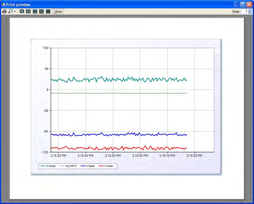
84 Local Diagnostics This application presents a real time snapshot of MultiPoint setups that measure the signal to noise level of the radio. This information may be taken from a Slave, Repeater, or Slave/Repeater radio. NOTE: In order to run Local Diagnostics the user must set the connected radio s Diagnostics (located under the Multi-Point Parameters tab in the Configuration application) to a value greater than zero. This information may be used to help direct a directional antenna of a slave radio by tracking the signal and noise levels as the antenna is aimed back at the Repeater or Master. When viewing, ensure the correct COM Port is set. Click Start to run the diagnostics. Click Stop to cease the diagnostics. As of Tool Suite release 2.4.0, users now have the capability to print the current view of the graph. Select the Print button to bring up a print preview of the graph. To print, hit the printer icon in the upper left corner of the print preview window. The document will be sent to the default printer selected on the user s computer. 84
85 85

86 Spectrum Tool The Spectrum Tool application puts a supported serial radio into a listening mode that monitors the ambient noise at various spectrum points as the radio hops through them. NOTE: This application is only available for 900MHz, 2.4GHz, and 1.3GHz radios only. Connect the radio for analysis and select Start. Tool Suite will prompt the user that using the Spectrum Tool application will cause the radio to go offline and requires the user to either select Yes to proceed, or No to cancel and exit the prompt. Hitting Reset Data resets the Peak and Average trend lines. Select Stop to cease listening to the radio. As of Tool Suite release 2.4.0, users now have the capability to print the current view of the graph. Select the Print button to bring up a print preview of the graph. To print, hit the printer icon in the upper left 86

87 corner of the print preview window. The document will be sent to the default printer selected on the user s computer. 87


88 Setup Terminal The Setup Terminal functionality allows the user to configure a radio using a terminal window. Click Connect to run the terminal window. Make sure that you do not have diagnostics running. NOTE: All changes made through the terminal window are immediate. A menu will appear on the screen allowing the user to start configuring the radio via terminal window. Be sure to hit the Disconnect button (or on the keyboard the ESC button at least twice) to exit the Terminal Window screen before configuring or running diagnostics on radios. 88


89 CP Data Logger The FreeWave Technologies CP DataLogger is an application that provides basic polling and reporting functions for FreeWave Cathodic Protection Remote Monitoring Units. CP Data Logger Settings When using CP Data Logger for the first time, the user will need to configure a network. Network Settings 1. Click Settings, to open the Network Settings dialogue box. 2. Name Network: The user can define a name for the network to be polled. NOTE: Default will be displayed as the network name in the status bar, unless the user selects a network name or the field is cleared. 89
90 3. Network Connection Type: Under the Network tab, there are two options for establishing a connection with the DataLogger software. a. Serial i. Connecting to the main port via a serial cable. ii. Choose a COM port, set the parity, baud rate, and turn Flow Control ON or OFF. iii. If the connected CP unit is a 2.4GHz Sand High Impedance device, check the High Impedance box. NOTE: Refer to CP Data Logger Serial/TCP Settings for configuring a serial connection. b. TCP i. Connect via Terminal Server. ii. The user will need to know the Terminal Server IP address and Port number that the FGR serial master is connected to. iii. If the connected CP unit is a 2.4GHz Sand High Impedance device, check the High Impedance box. NOTE: Refer to CP Data Logger Serial/TCP Settings for entering terminal information. 90

91 4. Add Notes: An alpha-numeric field available for use at the user s discretion; up to 100 characters. This area can be left blank. CP Data Logger Modbus Settings! Address Length: Select the length of the Modbus address. It will be either 8-bit or 16-bit. The address length must match the address length selected in the FGR-CP radios.! Poll Timeout: Define the number of milliseconds the Master waits for a response from a poll; between 100 and 5,000. NOTE: The default and recommended value is 3000 (3000 = 3 seconds). Also keep in mind that the higher the number, the longer the Master will wait before timing out (ex = 5 seconds).! Interval Timeout: Set the number of milliseconds the Master will wait between polling each site; measured in milliseconds between 50 and
; measured in seconds between 1 and 60.")
92 ! Instant Off Repeats: Controls the number of times the Rectifier Interrupt cycle is repeated; between 1 and 25.! Relay ON Delay: Select the amount of time the relay is turned on (disabling the rectifier); measured in seconds between 1 and 60.! Relay OFF Delay: Determine the number of seconds the relay is turned off (enabling the rectifier); between 1 and

93 ! Charge Delay: Choose a length of time (in seconds) to wait for the measurement capacitors to charge; between 1 and 200. CP Data Logger Serial/TCP Settings Serial Connection Configure a Serial Connection: The Baud Rate, Parity, and Flow Control MUST match the Master radio s settings. 1. If the COM port that is in use is not already selected, choose the correct COM port from the dropdown list provided. 2. Select the baud rate. 93
 or OFF (the box is unchecked). 5.")

94 3. Choose the parity. 4. Turn Flow Control either ON (the box is checked) or OFF (the box is unchecked). 5. Once the network is setup with the desired settings, click OK to save the changes and close Network Settings, or click Cancel to exit without saving changes TCP Connection Configure a TCP Connection: 1. Enter the Terminal Address (IP Address) of the terminal server. 94

95 2. Enter the Terminal Port number the serial master is connected to. 3. Once the network is setup, click OK to save the changes and close Network Settings, or click Cancel to exit without saving changes. CP Data Logger Options To add a site or group, refresh the network tree, or delete an entire network, either click on the Options drop down or right-click in the tree view. Add Group Add a folder for a specific set of sites that will be polled at the same time. 1. Click the Options button or right-click in the Network window pane and select Add Group. 2. The user can define a name for the group(s) to be polled. NOTE: New Group will be displayed as the Group name in the tree view, unless the user selects a group name or the field is cleared. 95


96 3. Enter a Description: an alpha-numeric field available for use at the user s discretion; up to 100 characters. This area can be left blank. 4. Set Poll Interval and Poll Start: Set how often the DataLogger will collect data from the sites in the group and when in the interval to start polling. The interval chosen will display under Polling under the group name in the tree view. a. Hourly: Polling can be set to start on minute 1 (:01) up to minute 59 (:59) of every hour. b. Daily: Choose which hour polling will begin on each day. Polling can be set to start on any hour from 1AM to 11PM. c. Weekly: Choose the initial day and date the poller will start on the displayed calendar. The poller will continue to poll each week on the specified day at midnight (12AM). d. Monthly: Choose the initial day and date the poller will begin for the month. The poller will continue to poll each month on the specified date (5 th of each month) at midnight (12AM). 96

97 e. Active/Inactive: The user can activate or inactivate an entire group, which activates or inactivates all sites within that group for polling. This can also be achieved by rightclicking on the group. i. Active: ii. Inactive: Add Site Add and configure an individual Cathodic Protection radio. 1. Click the Options button or right-click in the Network window pane and select Add Site. 97


98 2. Click the Configuration tab at the bottom of the Data Logger screen to setup the site. Name Site The user can define a name for the site(s) to be polled. NOTE: New Site will be displayed as the Group name in the tree view, unless the user selects a site name or the field is cleared. 98
99 Coordinates GPS coordinates or notes can be entered in this field at the user s discretion. Shunt Resistance The user must enter the value of the shunt resistor. Modbus ID Be sure to enter the same Modbus ID as the site that will be polled. Poll Interval and Poll Start Set how often the Data Logger will collect data from the site and when in the interval to start polling. The interval chosen will display under Polling under the site name in the tree view.! Hourly: Set the start time starting on the 1 st minute (:01) up to the 59 th minute (:59) of every hour.! Daily: Choose which hour polling will begin on each day. Polling can start on any hour from 1AM to 11PM.! Weekly: Choose the initial day and date the poller starts on the displayed calendar. The poller continues to poll each week on the specified day starting at midnight (12AM).! Monthly: Choose the initial day and date the poller will begin each month. The poller continues to poll each month on the specified date (5 th of each month) at midnight (12AM). Active/Inactive The user can activate or inactivate an individual site for polling. To poll a single site at one time, inactivate any active groups or other individual sites within the network. This can also be achieved by right-clicking on the individual site.! Active:! Inactive: NOTE: Inactivating a single site within a group only inactivates that specific site. Alarms User definable alert values that signal the user if the site goes outside of the specified value(s). Below are recommended alarm values. This section or specific alarms can be left blank.! Analog Input: Set the low limit at or below a value of 0 and the high limit at or above a value of 6 (measured in VDC)! Rectifier Shunt Voltage: Set the low limit at or below a value of -1.6 and the high limit at or above a value of 1.6 (measured in mvdc)! Rectifier Voltage: Set the low and high limits at an impossible range (measured in mvdc)! Pipe to Soil: Set the low limit at or below a value of -1.6 and the high limit at or above a value of 1.6 (measured in mvdc)! Battery Voltage: Set the low limit at or below a value of 5 and the high limit at or above 31 (measured in VDC) 99
100 ! Temperature: Set the low limit at or below a value of -36 and the high limit at or above a value of 76 (measured in C) Enable Discrete Output Programming & Enable VSNS Programming In order to activate the Discrete Out and/or VSNS programming button(s) on the toolbar the user must select each desired checkbox prior to using either programming function. Please refer to the section on CP Data Logger Programming for more information on the individual functions. Refresh Selecting Refresh updates the sites, and then the groups in the tree view. Clear Network Selecting Clear Network deletes all sites and groups within the entire network. NOTE: A single site can be deleted by right-clicking on the specific site for deletion and selecting Delete. Start and Stop Polling 1. To start Polling data, click Connect in the Network section of the ribbon. 2. To stop the Poller, click Disconnect. Read Latest By clicking Read Latest in the Poll Commands section of the ribbon, the user can retrieve stored Modbus data from the connected site.! If a graph does not appear upon connecting, hit Read Latest to populate the screen with the view of a graph, hit Read Latest again to populate data on the graph. 100

101 Zoom Functionality Tool Suite allows the user to zoom in multiple times on a specific area of data on the graph. The ax- and Y-axes adjust as the graph is zoomed in or out. 5. To zoom in on a specific area of the graph, hold down the left button on the mouse at the uppermost or lowest point of the area on the graph to zoom in on 6. Drag the mouse across the entire area the user wishes to zoom in on. This step can repeated multiple times for greater magnification. 7. To zoom out, click the O in either the top upper left corner (controls zooming out at the Y-axis) and/or the lower left corner (controls zooming out at the X-axis) of the graph. The user can alternate between zooming out on the X- or Y- axis. NOTE: The number of times the graph was magnified equals the number of times the user needs to click either one of the reset points to return the graph to the normal view. 101
102 CP Data Logger Polling Commands Force Refresh Force the radio to cycle relays, which refreshes the measurements of the charging capacitors. 102
103 NOTE: The status of the polling command is displayed at the bottom of the screen. FreeWave Tool Suite Rectifier Interrupt Each time Rectifier Interrupt is clicked it turns off the rectifier and goes through one ON, OFF, CHARGE relay cycle. NOTE: The status of the polling command is displayed at the bottom of the screen. Perform Instant Off This function engages Instant Off Repeats previously defined by the user in the Network Settings. 103

104 NOTE: The status of the polling command is displayed at the bottom of the screen. CP Data Logger Programming Discrete Out Controls the Relay Digital Output on the CP Interface Board. When turned ON it disconnects the rectifier from the pipe. 104
105 NOTE: For more detailed information on programming the Discrete Output, please refer to the Cathodic Protection Manual Addendum (Document # LAD0014AA, page 6, Section COILS # 13 Interrupter Relay Driver ) on the FreeWave Utilities CD. VSNS This function allows remote controllable power to an analog sensor. 105
106 NOTE: For more detailed information on programming the Sensor Power (VSNS), please refer to the Cathodic Protection Manual Addendum (Document # LAD0014AA, page 6, Section COILS # 2 SENSOR POWER ) on the FreeWave Utilities CD. Summary View Displays the most recent polls and provides an overview of all the sites and groups within the network on a single page. NOTE: If the Rectifier Input Status is ON in the site, then the check box will be checked in the Summary View. It cannot be manipulated from this view. History Located at the bottom of the Data Logger screen, displays at-a-glance history for an individual site: what was polled and what the reading was at that time of polling. The history tab is refreshed as often as a radio is polled. 106

107 View Report To save or print the history data, right-click on the specific site and select View Report. 1. Specify the date range of the data to view. 107


108 2. Click Report to bring up the report viewer, or Cancel to exit. 3. Once the report is populated, to save/export as either an Adobe PDF or an Excel spreadsheet, click the disk icon on the report. To print, click the printer icon. 4. Save the report to a folder on the computer and click Save. 108


109 Updates The Update application lists the most current release notes and allows the user to update Tool Suite to the latest software versions. The software first downloads the updates and then installs them. NOTE: Updating Tool Suite upon Program Start-up and from an Open Session requires an internet connection. Updating Tool Suite upon Program Start-up 1. If a new update is available, upon opening a new session of Tool Suite, a prompt will automatically appear informing the user that new updates are available. If you would like Tool Suite to automatically download the update, click Yes. The user is then automatically taken to the Updates Application and Tool Suite downloads the update. Otherwise, click No to exit the prompt and access Tool Suite normally. 2. Once the update is downloaded, Tool Suite will prompt the user to install the update by clicking the Apply Updates button, which should now be highlighted. 3. Once the user confirms that they would like to install the update, Tool Suite will automatically reload and then re-launch once the install is complete and successful. A status Updating window will appear while the update is in progress. 109


110 Updating Tool Suite from an Open Session 1. If Tool Suite is currently open, and the user would like to manually check for updates, in the Applications menu, click Updates. 2. To manually check for updates to the software (and if prompted at the beginning of a Tool Suite session), click Check Updates. 3. A pop up window will tell the user whether or not updates are available and ask for confirmation to download. Select Yes to download updates. Otherwise click No to exit the prompt without downloading the update. 4. When the download process is complete a message will appear prompting the user to click Apply Updates to install the updates. Click OK to proceed. 110
111 5. The Apply Updates button will no longer be greyed out. To install the updates, click Apply Updates. 6. Once the user confirms that they would like to install the update, Tool Suite will automatically reload and then re-launch once the install is complete and successful. 111

112 Updating Tool Suite Locally To update computers and/or laptops that do not have access to an internet connection, Tool Suite has a function which allows the user to download the latest update package to a computer that has an internet connection, and either distribute it by a network drive, or to a jump drive or a CD that can be taken out into the field or throughout an office. 1. To install a Tool Suite update package for a Local Update, the user must first download the package from the FreeWave website at 2. Save the package to a folder on a local or network drive, or on a jump drive or CD, for convenient access later. 3. Once the update package has been saved to the desired location (if the package has been saved to a jump drive or CD, make sure the hardware is plugged into the computer or the CD with the update package is in the computer s CD-ROM), from the Applications menu, click Updates. 4. Click Local Update. 5. Tool Suite will navigate to the last folder that was accessed through the software. The user may need to navigate to the appropriate folder that contains the update package. 6. Once the package is located, click Open to install the package. 7. Once the user confirms that they would like to install the update, Tool Suite will automatically reload and then re-launch once the install is complete and successful. 112
EZ Config V2.3 Instructions
 FreeWave EZ Config is GUI-based setup software that is designed to provide reliable, easy-touse, repeatable programming for FreeWave wireless data transceivers. This version of EZ Config is compatible
NETWORK PRINT MONITOR User Guide
 NETWORK PRINT MONITOR User Guide Legal Notes Unauthorized reproduction of all or part of this guide is prohibited. The information in this guide is subject to change for improvement without notice. We
KMnet Viewer. User Guide
 KMnet Viewer User Guide Legal Notes Unauthorized reproduction of all or part of this guide is prohibited. The information in this guide is subject to change for improvement without notice. We cannot be
Using LCS Help. In This Section
 Using LCS Help We want to help you get the most out of Square D Lighting Control Software (LCS) system by Schneider Electric. This Help system contains most of the information you'll need to successfully
Version /20/2012. User Manual. AP Manager II Lite Business Class Networking
 Version 1.0 12/20/2012 User Manual AP Manager II Lite Business Class Networking Table of Contents Table of Contents Product Overview... 1 Minimum System Requirements... 2 Access Point Requirements... 2
DCP585CW Windows Network Connection Repair Instructions
 Difficulty printing from your PC can occur for various reasons. The most common reason a networked Brother machine may stop printing, is because the connection between the computer and the Brother machine
IBM NetBAY Virtual Console Software. Installer and User Guide
 IBM NetBAY Virtual Console Software Installer and User Guide INSTRUCTIONS This symbol is intended to alert the user to the presence of important operating and maintenance (servicing) instructions in the
Legal Notes. Regarding Trademarks KYOCERA MITA Corporation
 Legal Notes Unauthorized reproduction of all or part of this guide is prohibited. The information in this guide is subject to change without notice. We cannot be held liable for any problems arising from
DBT-120 Bluetooth USB Adapter
 DBT-120 Bluetooth USB Adapter Rev.2.1 (09/25/2002) 2 Contents Introduction... 5 Package Contents... 6 Installing Bluetooth Software... 6 Hardware Installation... 8 Introduction to Bluetooth Software...
IBM NetBAY Virtual Console Software. Installer and User Guide
 IBM NetBAY Virtual Console Software Installer and User Guide INSTRUCTIONS This symbol is intended to alert the user to the presence of important operating and maintenance (servicing) instructions in the
KYOCERA Net Viewer 5.3 User Guide
 KYOCERA Net Viewer. User Guide Legal Notes Unauthorized reproduction of all or part of this guide is prohibited. The information in this guide is subject to change without notice. We cannot be held liable
Legal Notes. Regarding Trademarks KYOCERA MITA Corporation
 Legal Notes Unauthorized reproduction of all or part of this guide is prohibited. The information in this guide is subject to change without notice. We cannot be held liable for any problems arising from
Apptix Online Backup by Mozy User Guide
 Apptix Online Backup by Mozy User Guide 1.10.1.2 Contents Chapter 1: Overview...5 Chapter 2: Installing Apptix Online Backup by Mozy...7 Downloading the Apptix Online Backup by Mozy Client...7 Installing
KYOCERA Net Admin User Guide
 KYOCERA Net Admin User Guide Legal Notes Unauthorized reproduction of all or part of this guide is prohibited. The information in this guide is subject to change without notice. We cannot be held liable
KYOCERA Net Viewer User Guide
 KYOCERA Net Viewer User Guide Legal Notes Unauthorized reproduction of all or part of this guide is prohibited. The information in this guide is subject to change without notice. We cannot be held liable
Version 4.1 June Xerox Device Agent (XDA) Lite User Guide
 Lite User Guide") Version 4.1 June 2013 Xerox Device Agent (XDA) Lite User Guide 2008-2013 Xerox Corporation. All rights reserved. Xerox and Xerox and Design are trademarks of Xerox Corporation in the US and/or other countries.
Version 4.1 June 2013 Xerox Device Agent (XDA) Lite User Guide 2008-2013 Xerox Corporation. All rights reserved. Xerox and Xerox and Design are trademarks of Xerox Corporation in the US and/or other countries.
USING THE XPERT2 / 9210B ON A TCP/IP NETWORK
 1 USING THE XPERT2 / 9210B ON A TCP/IP NETWORK Prepared by: R&D January, 2009 Updated September 26, 2013 Sutron Corporation 22400 Davis Drive Sterling, Virginia 20164 TEL: (703) 406-2800 FAX: (703) 406-2801
Calendar & Buttons Dashboard Menu Features My Profile My Favorites Watch List Adding a New Request...
 remitview User Guide 1 TABLE OF CONTENTS INTRODUCTION... 3 Calendar & Buttons... 3 GETTING STARTED.... 5 Dashboard.... 7 Menu Features... 8 PROFILE.... 10 My Profile... 10 My Favorites... 12 Watch List...
MFC790CW Windows Network Connection Repair Instructions
 Difficulty printing from your PC can occur for various reasons. The most common reason a networked Brother machine may stop printing, is because the connection between the computer and the Brother machine
Manual. bintec elmeg GmbH. Manual. bintec elmeg Dime Manager. Copyright Version 1.3.8, 2013 bintec elmeg GmbH
 Manual Manual Copyright Version 1.3.8, 2013 1 Manual Legal Notice Warranty This publication is subject to change. offers no warranty whatsoever for information contained in this manual. is not liable for
Application Note #5494 Upgrading Plus Ethernet Radio Firmware September 9, 2013
 Application Note #5494 Upgrading Plus Ethernet Radio Firmware September 9, 2013 The Plus Ethernet transceivers share a common firmware upgrade platform and process using the FreeWave TFTP Server and a
Argosy University Online Programs, Version 7.0. digital bookshelf. Student User Guide
 Argosy University Online Programs, Version 7.0 digital bookshelf Student User Guide 1 Take your ebooks with you! Download the Bookshelf app. If you own an iphone, ipad, or ipod Touch, you can download
Bluetooth PC Card from IBM
 Bluetooth PC Card from IBM Installation and User s Guide IBM 19K4260 Note: Before using this information and the product it supports, read Appendix E, Product warranties and notices on page E-1. First
Oct 2007 Version 1.01
 Oct 2007 Version 1.01 Table of Contents Introduction...4 System Requirement...4 Getting Started...4 Installing the Smart WLAN Manager...5 Discovering the Switch and AP...9 Understanding the Screen Layout...12
Printing System Driver User Guide
 Printing System Driver User Guide Legal Notes Unauthorized reproduction of all or part of this guide is prohibited. The information in this guide is subject to change for improvement without notice. We
Wireless-G Router User s Guide
 Wireless-G Router User s Guide 1 Table of Contents Chapter 1: Introduction Installing Your Router System Requirements Installation Instructions Chapter 2: Preparing Your Network Preparing Your Network
IQSweb Installation Instructions Version 5.0
 IQSweb Installation Instructions Version 5.0 Contents Additional References... 3 IQSweb ROSS Connection... 3 IQSweb V5.0 Install/Upgrade Scenarios... 4 IQSweb Configuration Options... 5 A. Single Computer/Server
BackupVault Desktop & Laptop Edition. USER MANUAL For Microsoft Windows
 BackupVault Desktop & Laptop Edition USER MANUAL For Microsoft Windows Copyright Notice & Proprietary Information Blueraq Networks Ltd, 2017. All rights reserved. Trademarks - Microsoft, Windows, Microsoft
VSM Manager. The VSM Manager is a Windows GUI that can be installed to serially control Genesis Matrixes with a firmware of version 2.5 or later.
 VSM Manager Table of Contents Overview...1 Getting Started...1 Toolbar... 2 Serial Connection... 2 Refresh... 3 Help... 3 Tab Pages... 4 General... 4 Control...5 Schedule... 6 Command... 6 Communications...
Print Server. User s Manual. Rev. 01 (April, 2004) Made In Taiwan
 Made In Taiwan") Print Server User s Manual Rev. 01 (April, 2004) Made In Taiwan TABLE OF CONTENTS ABOUT THIS GUIDE... 4 INTRODUCTION... 5 PACKAGE CONTENTS... 6 SYSTEM REQUIREMENTS... 6 GENERAL FEATURES... 7 PRODUCT VIEW...
Print Server User s Manual Rev. 01 (April, 2004) Made In Taiwan TABLE OF CONTENTS ABOUT THIS GUIDE... 4 INTRODUCTION... 5 PACKAGE CONTENTS... 6 SYSTEM REQUIREMENTS... 6 GENERAL FEATURES... 7 PRODUCT VIEW...
Legal Notes. Regarding Trademarks. Models supported by the KX printer driver KYOCERA MITA Corporation
 Legal Notes Unauthorized reproduction of all or part of this guide is prohibited. The information in this guide is subject to change without notice. We cannot be held liable for any problems arising from
MX OPC Server 5.0 Help Documentation
 5.0 Help Documentation Contents 1. Introduction to MX OPC Server 1-1 2. Starting MX OPC Server Configuration 2-1 3. Address Space 3-1 4. Alarm Definitions 4-1 5. Simulation Signals 5-1 6. Runtime Operations
User Guide. Rev Dot Origin Ltd.
 User Guide Introduction to the EasyTac File Explorer...1 Using EasyTac to read drivers' cards with a card reader...2 Using EasyTac to read VU files from a download device...3 Using EasyTac to download
A Division of Cisco Systems, Inc. GHz g. Wireless-G. USB Network Adapter. User Guide WIRELESS WUSB54G. Model No.
 A Division of Cisco Systems, Inc. GHz 2.4 802.11g WIRELESS Wireless-G USB Network Adapter User Guide Model No. WUSB54G Copyright and Trademarks Specifications are subject to change without notice. Linksys
Network Management Utility
 4343-7705-02 Network Management Utility Foreword Welcome Network Management Utility is utility software that provides central control over printers, copiers, and other devices on a network. With Network
The Administration Tab - Diagnostics
 The Administration Tab - Diagnostics The diagnostic tests (Ping and Traceroute) allow you to check the connections of your network components. Ping Test. The Ping test will check the status of a connection.
IT Essentials v6.0 Windows 10 Software Labs
 IT Essentials v6.0 Windows 10 Software Labs 5.2.1.7 Install Windows 10... 1 5.2.1.10 Check for Updates in Windows 10... 10 5.2.4.7 Create a Partition in Windows 10... 16 6.1.1.5 Task Manager in Windows
EFI Fiery Utilities Technical Reference. Part Number: , Rev. 1.0
 EFI Fiery Utilities Technical Reference Part Number: 59308805, Rev. 1.0 15 March 2008 CONTENTS 3 CONTENTS INTRODUCTION 5 Terminology and conventions 6 About this document 7 About Help 7 Preparing for installation
User Guide 701P Wide Format Solution Wide Format Scan Service
 User Guide 701P44865 6204 Wide Format Solution Wide Format Scan Service Xerox Corporation Global Knowledge & Language Services 800 Phillips Road Bldg. 845-17S Webster, NY 14580 Copyright 2006 Xerox Corporation.
Network USB over IP Server With 1-USB2.0 Port. User Manual V1.0
 Network USB over IP Server With 1-USB2.0 Port User Manual V1.0 1 2 TABLE OF CONTENTS COPYRIGHT...4 1. INTRODUCTION...5 PRODUCT OVERVIEW...5 COMPONENTS AND FEATURES...5 HARDWARE INSTALLATION...5 2. THE
Server Edition USER MANUAL. For Microsoft Windows
 Server Edition USER MANUAL For Microsoft Windows Copyright Notice & Proprietary Information Redstor Limited, 2016. All rights reserved. Trademarks - Microsoft, Windows, Microsoft Windows, Microsoft Windows
Bluetooth Application Note
 Bluetooth Application Note FCC Interference Statement This equipment has been tested and found to comply with the limits for a Class B digital device pursuant to Part 15 of the FCC Rules. These limits
SWP-0036 AFHCAN Telehealth Cart Imaging and Software Configuration. Revision: 1. Effective Date: 1/4/2011
 Software Procedure SWP-0036 AFHCAN Telehealth Cart Imaging and Software Configuration Revision: 1 Effective Date: 1/4/2011 Alaska Native Tribal Health Consortium Division of Health Information & Technology
Printer Driver User Guide
 PRINT COPY SCAN FAX TASKalfa 0i TASKalfa i Printer Driver User Guide Legal Notes Unauthorized reproduction of all or part of this guide is prohibited. The information in this guide is subject to change
A Division of Cisco Systems, Inc. GHz 2, g. Wireless-G. User Guide. PCI Adapter WIRELESS. with SpeedBooster WMP54GS (EU/UK/LA) Model No.
 Model No.") A Division of Cisco Systems, Inc. GHz 2,4 802.11g WIRELESS Wireless-G PCI Adapter with SpeedBooster User Guide Model No. WMP54GS (EU/UK/LA) Copyright and Trademarks Specifications are subject to change
A Division of Cisco Systems, Inc. GHz 2,4 802.11g WIRELESS Wireless-G PCI Adapter with SpeedBooster User Guide Model No. WMP54GS (EU/UK/LA) Copyright and Trademarks Specifications are subject to change
Wireless USB Port Multi-Functional Printer Server. Model # AMPS240W. User s Manual. Ver. 1A
 Wireless USB 2.0 1-Port Multi-Functional Printer Server Model # AMPS240W User s Manual Ver. 1A Table of Contents 1 Introduction...3 1.1 Package Contents... 3 1.2 System Requirements... 3 2 Multi-Functional
ebob v5.2 Operator s Manual
 ebob v5.2 Operator s Manual BinMaster Division of Garner Industries 7201 North 98 th Street Lincoln, NE 68507 402-434-9102 info@binmaster.com www.binmaster.com 925-0267 Rev E 10/1/2013 (this page intentionally
Legal Notes. Regarding Trademarks. Models supported by the KX printer driver KYOCERA Document Solutions Inc.
 Legal Notes Unauthorized reproduction of all or part of this guide is prohibited. The information in this guide is subject to change without notice. We cannot be held liable for any problems arising from
Table of Contents. 1 Introduction. 2 Wireless Configurations. 3 Setting Up your LAN Administrator Station
 Table of Contents 1 Introduction About Avaya Wireless 1-1 About Avaya Wireless Tools 1-2 About Avaya Wireless Access Points 1-5 About This User s Guide 1-6 About Icons used in this Document 1-7 On-line
HR-Lite Database & Web Service Setup Guide
 HR-Lite Database & Web Service Setup Guide Version: 1.00 HR21 Limited All rights reserved. No part of this document may be reproduced or transmitted in any form or by any means, electronic or mechanical,
User Manual Device Manager
 User Manual About this document This document describes the application, that is used for administration of devices. Contents 1.... 1 1.1 Basic Terminology... 1 2. The GUI... 2 2.1 Sort and Filter the
KYOCERA Net Viewer User Guide Supplement
 KYOCERA Net Viewer User Guide Supplement Legal Notes Unauthorized reproduction of all or part of this guide is prohibited. The information in this guide is subject to change without notice. We cannot be
A Division of Cisco Systems, Inc. GHz g. Wireless-G. PCI Adapter with SRX 400. User Guide WIRELESS WMP54GX4. Model No.
 A Division of Cisco Systems, Inc. GHz 2.4 802.11g WIRELESS Wireless-G PCI Adapter with SRX 400 User Guide Model No. WMP54GX4 Copyright and Trademarks Specifications are subject to change without notice.
PMS 138 C Moto Black spine width spine width 100% 100%
 Series MOTOROLA and the Stylized M Logo are registered in the US Patent & Trademark Office. All other product or service names are the property of their respective owners. 2009 Motorola, Inc. Table of
A Division of Cisco Systems, Inc. GHz 2, g. Wireless-G. User Guide. Access Point WIRELESS WAP54G (EU/LA/UK) Model No.
 Model No.") A Division of Cisco Systems, Inc. GHz 2,4 802.11g WIRELESS Wireless-G Access Point User Guide Model No. WAP54G (EU/LA/UK) Copyright and Trademarks Specifications are subject to change without notice. Linksys
A Division of Cisco Systems, Inc. GHz 2,4 802.11g WIRELESS Wireless-G Access Point User Guide Model No. WAP54G (EU/LA/UK) Copyright and Trademarks Specifications are subject to change without notice. Linksys
Legal Notes. Regarding Trademarks. Models supported by the KX printer driver KYOCERA MITA Corporation
 Legal Notes Unauthorized reproduction of all or part of this guide is prohibited. The information in this guide is subject to change without notice. We cannot be held liable for any problems arising from
Server Edition. V8 Peregrine User Manual. for Microsoft Windows
 Server Edition V8 Peregrine User Manual for Microsoft Windows Copyright Notice and Proprietary Information All rights reserved. Attix5, 2015 Trademarks - Microsoft, Windows, Microsoft Windows, Microsoft
Printer Driver User Guide
 PRINT COPY SCAN FAX TASKalfa 700i TASKalfa 800i Printer Driver User Guide Legal Notes Unauthorized reproduction of all or part of this guide is prohibited. The information in this guide is subject to change
User Guide. Web Intelligence Rich Client. Business Objects 4.1
 User Guide Web Intelligence Rich Client Business Objects 4.1 2 P a g e Web Intelligence 4.1 User Guide Web Intelligence 4.1 User Guide Contents Getting Started in Web Intelligence 4.1... 5 Log into EDDIE...
A Division of Cisco Systems, Inc. GHz g. Wireless-G. Access Point. User Guide WIRELESS. WAP54G ver Model No.
 A Division of Cisco Systems, Inc. GHz 2.4 802.11g WIRELESS Wireless-G Access Point User Guide Model No. WAP54G ver. 3.1 Copyright and Trademarks Specifications are subject to change without notice. Linksys
LevelOne. User's Guide. Broadband Router FBR-1402TX FBR-1403TX
 LevelOne Broadband Router FBR-1402TX FBR-1403TX User's Guide Table of Contents CHAPTER 1 INTRODUCTION... 1 LevelOne Broadband Router Features... 1 Package Contents... 3 Physical Details...4 CHAPTER 2 INSTALLATION...
Controlsoft Identity and Access Management Software Controlsoft Identity Access Management Software
 Controlsoft Identity Access Management Software IA Server Software Installation Guide v8.0.229 2018 Controlsoft Ltd 9010-0050 Issue 6 Page 1 of 39 29/10/2018 Contents 1. Introduction... 3 1.1. PC Specifications...
A Division of Cisco Systems, Inc. Dual-Band. Wireless A/G g a. User Guide. Game Adapter WIRELESS WGA54AG (EU/LA/UK) Model No.
 Model No.") A Division of Cisco Systems, Inc. Dual-Band 5GHz 2, 4GHz 802.11a 802.11g WIRELESS Wireless A/G Game Adapter User Guide Model No. WGA54AG (EU/LA/UK) Copyright and Trademarks Specifications are subject to
A Division of Cisco Systems, Inc. Dual-Band 5GHz 2, 4GHz 802.11a 802.11g WIRELESS Wireless A/G Game Adapter User Guide Model No. WGA54AG (EU/LA/UK) Copyright and Trademarks Specifications are subject to
Printer Driver User Guide
 PRINT ECOSYS P500cdn ECOSYS P500cdw ECOSYS P50cdn ECOSYS P50cdw ECOSYS P505cdn ECOSYS P506cdn ECOSYS P506cdw Printer Driver User Guide PRINT COPY SCAN FAX ECOSYS M550cdn ECOSYS M550cdw ECOSYS M55cdn ECOSYS
DATA ARCHIVING SOFTWARE V.
 Interscan Corporation. ARC-MAX III - DATA ARCHIVING SOFTWARE V. 2.1.0.9 OPERATION MANUAL 1 Contents 1 Opening the program.... 3 2 Login Window... 3 2 Menu & Toolbar... 4 2.1 Current Data Display... 5 2.2
9936A LogWare III. User s Guide. Revision
 9936A LogWare III User s Guide Revision 680301 Table of Contents 1 Introduction... 1 1.1 Symbols Used...1 1.2 Conventions...1 1.3 What is LogWare?...1 1.4 License Agreement...2 1.5 Requirements...2 1.6
Printer Driver User Guide
 PRINT COPY SCAN FAX ECOSYS M660idn ECOSYS M655idn ECOSYS M65idn ECOSYS M65dn Printer Driver User Guide PRINT COPY SCAN ECOSYS M5idn ECOSTS M5dn Legal Notes Unauthorized reproduction of all or part of this
IntesisBox MAPS. Configuration & monitoring software of IntesisBox KNX series. User's manual Issue Date: 06/17 r1.0 eng
 IntesisBox MAPS Configuration & monitoring software of IntesisBox KNX series User's manual Issue Date: 06/17 r1.0 eng Intesis Software S.L.U. 2017 All Rights Reserved. Information in this document is subject
Network Management Software ALLNET Zone Controller
 Network Management Software ALLNET Zone Controller For ALL0558N / ALL02850N / ALL02860ND / ALL02880ND User Manual v1.0 Table of Contents 1. Installation & Un-installation... 4 1.1. Install NMS Suite...
Top Producer for Palm Handhelds
 Top Producer for Palm Handhelds Quick Setup Top Producer Systems Phone number: 1-800-830-8300 Email: support@topproducer.com www.topproducer.com Fax: 604.270.6365 Top Producer for Palm handhelds Quick
Chapter 1 Getting Started with Switch Management
 Chapter 1 Getting Started with Switch Management This section provides an overview of switch management, including the methods you can choose to start managing your NETGEAR GS700TS Gigabit Stackable Smart
ATX Document Manager. User Guide
 ATX Document Manager User Guide ATX DOCUMENT MANAGER User Guide 2008 CCH Small Firm Services. All rights reserved. 6 Mathis Drive NW Rome, GA 30165 No part of this manuscript may be copied, photocopied,
CityVault Client Manual
 CityVault Client Manual Contents Preface: Preface...4 Chapter 1: Overview...5 Chapter 2: Installing CityVault...6 Downloading the CityVault Client...6 Installing the CityVault Client...6 Configuring CityVault...8
Covering Firmware v. 2.18
 Version 4.0 LUM0009AB Rev C Covering Firmware v. 2.18 1 SPREAD SPECTRUM WIRELESS DATA TRANSCEIVER USER MANUAL Copyright 1995-2008 by FreeWave Technologies, Inc. All rights reserved. Published 2008. WARRANTY
Display Manager Version 1.0
 Introduction Basics Adjustments and Controls Troubleshooting Appendix Display Management Utility Software Display Manager Version 1.0 For Windows Operation Manual Please read this operation manual carefully
installation manual SALES AND ADMINISTRATION (toll free)
") installation manual SALES AND ADMINISTRATION 800.637.2645 (toll free) 217.442.0611 sales@timeomatic.com TECHNICAL SUPPORT 866.637.2645 (toll free) service@timeomatic.com www.watchfiresigns.com Quick Start-Up
installation manual SALES AND ADMINISTRATION 800.637.2645 (toll free) 217.442.0611 sales@timeomatic.com TECHNICAL SUPPORT 866.637.2645 (toll free) service@timeomatic.com www.watchfiresigns.com Quick Start-Up
3.0. Manual and. Application note. USB Adapter
 3.0 USB Adapter Manual and Application note Index INTRODUCTION 1 CHAPTER 1 Package 2 Features 2 Bluetooth profile support 2 Drivers support 3 CHAPTER 2 Setup for Windows 98SE/ME/2000/XP 4 CHAPTER 3 Application
User Manual. MPPTracker. Management Software for Solar Charge Controller. Version: 1.2
 User Manual MPPTracker Management Software for Solar Charge Controller Version: 1.2 Table of Contents 1. MPPTracker Overview... 1 1.1. Introduction... 1 1.2. Features... 1 2. MPPTracker Install and Uninstall...
635-FTS Factory Programming Guide
 GALAXY CONTROL SYSTEMS 635-FTS Factory Programming Guide ( Supported on 635-CPU v10.4.9 - or later ) Factory Program & Flash with a 635 Factory Test Station(FTS) GALAXY TECHNICAL GUIDE 1 st EDITION SEP
LevelOne Broadband Routers
 LevelOne Broadband Routers FBR-1100TX FBR-1400TX FBR-1401TX FBR-1700TX User's Guide TABLE OF CONTENTS CHAPTER 1 INTRODUCTION... 1 Features of your LevelOne Broadband Router... 1 Package Contents... 4
TCP/IP CONFIGURATION 3-6
 TCP/IP CONFIGURATION 3. Type IPCONFIG /RENEW and press the Enter key. Verify that your IP Address is now 192.168.2.xxx, your Subnet Mask is 255.255.255.0 and your Default Gateway is 192.168.2.1. These
Vol. 1 Introduction. OMS-100 User Manual. Publishing version: V2.2. Publishing version: V2.2 1
 Vol. 1 Introduction OMS-100 User Manual Publishing version: V2.2 Publishing version: V2.2 1 OMS-100 User Manual Table of Contents I Vol. 1 Introduction 5 2 1 Foreword... 5 1.1 Typographical Conventions...
CompactFlash/SDIO Connection Kit with Bluetooth Wireless Technology
 CompactFlash/SDIO Connection Kit with Bluetooth Wireless Technology Featuring a Socket CompactFlash/SDIO card and Windows CE software for adding Bluetooth capability to the following mobile computers:
Legal Notes. Regarding Trademarks. Models supported by the KX printer driver KYOCERA Document Solutions Inc.
 Legal Notes Unauthorized reproduction of all or part of this guide is prohibited. The information in this guide is subject to change without notice. We cannot be held liable for any problems arising from
Legacy Client Chart (LCC) Installation Guide for Purkinje System
 Installation Guide for Purkinje System") Legacy Client Chart (LCC) Installation Guide for Purkinje System A Guide to Run and Configure the Legacy Client Chart (LCC) Solution For questions about using this guide please contact IMS@aohc.org Table
Legacy Client Chart (LCC) Installation Guide for Purkinje System A Guide to Run and Configure the Legacy Client Chart (LCC) Solution For questions about using this guide please contact IMS@aohc.org Table
Sound Manager 2 User Guide
 Sound Manager 2 User Guide Version 1.8.4 September 27 th, 2016 OVERVIEW 2 USER OPERATION 3-6 LOGIN SCREEN 7 OPTIONAL STEP 8-10 MAIN MENU 11 DEVICES TAB 11 ZONE TAB 12 EQ TAB 13 SOURCES TAB 14 SYSTEM TAB
Legal Notes. Regarding Trademarks. Models supported by the KX printer driver. Copyright 2009 KYOCERA MITA Corporation All rights reserved.
 Legal Notes Unauthorized reproduction of all or part of this guide is prohibited. The information in this guide is subject to change for improvement without notice. We cannot be held liable for any problems
Wireless-N. User Guide. USB Network Adapter WUSB300N WIRELESS. Model No.
 2.4 GHz WIRELESS Wireless-N USB Network Adapter User Guide Model No. WUSB300N Copyright and Trademarks Specifications are subject to change without notice. Linksys is a registered trademark or trademark
Legal Notes. Regarding Trademarks. Models supported by the KX printer driver KYOCERA MITA Corporation
 Legal Notes Unauthorized reproduction of all or part of this guide is prohibited. The information in this guide is subject to change without notice. We cannot be held liable for any problems arising from
Installation 3. PerTrac Reporting Studio Overview 4. The Report Design Window Overview 8. Designing the Report (an example) 13
 13") Contents Installation 3 PerTrac Reporting Studio Overview 4 The Report Design Window Overview 8 Designing the Report (an example) 13 PerTrac Reporting Studio Charts 14 Chart Editing/Formatting 17 PerTrac
Contents Installation 3 PerTrac Reporting Studio Overview 4 The Report Design Window Overview 8 Designing the Report (an example) 13 PerTrac Reporting Studio Charts 14 Chart Editing/Formatting 17 PerTrac
User Manual PDUTracker
 User Manual PDUTracker Management Software for PDU Table of Contents 1. Overview... 1 1.1. Introduction... 1 1.2. Features... 1 2. Install and Uninstall... 1 2.1. System Requirement... 1 2.2. Software
Synergy Application Software
 Synergy Application Software This document is written to provide an overview of the Synergy Application Software that controls the Discover Systems and their accessories. The information for the initial
User Manual. pdoc Forms Designer. Version 3.7 Last Update: May 25, Copyright 2018 Topaz Systems Inc. All rights reserved.
 User Manual pdoc Forms Designer Version 3.7 Last Update: May 25, 2018 Copyright 2018 Topaz Systems Inc. All rights reserved. For Topaz Systems, Inc. trademarks and patents, visit www.topazsystems.com/legal.
WVL2 Wireless Vehicle Link 2 Installation and Setup Manual
 WVL2 Wireless Vehicle Link 2 Installation and Setup Manual Chapter 1: Introducing the Wireless Vehicle Link 2...1 WVL2 Components...2 Component Checklist...3 Product Specifications...4 System Requirements...5
Creative USB Adapter CB2431 with Bluetooth Wireless Technology. User s Guide
 Creative USB Adapter CB2431 with Bluetooth Wireless Technology User s Guide Application Setup & User s Guide Information in this document is subject to change without notice and does not represent a commitment
Quick Start Guide for Windows
 for Windows The Eudora 5.1 User Manual for Windows is on the Eudora CD included in the product box. If you prefer a printed and bound copy, you can purchase one from www.eudora.com or call 1-800-2-EUDORA
Quick Start Guide - Contents. Opening Word Locating Big Lottery Fund Templates The Word 2013 Screen... 3
 Quick Start Guide - Contents Opening Word... 1 Locating Big Lottery Fund Templates... 2 The Word 2013 Screen... 3 Things You Might Be Looking For... 4 What s New On The Ribbon... 5 The Quick Access Toolbar...
GHz g. Wireless A+G. User Guide. Notebook Adapter. Dual-Band. Dual-Band WPC55AG a. A Division of Cisco Systems, Inc.
 A Division of Cisco Systems, Inc. Dual-Band 5 GHz 802.11a + GHz 2.4 802.11g WIRELESS Dual-Band Wireless A+G Notebook Adapter User Guide Model No. WPC55AG Copyright and Trademarks Specifications are subject
FaxFinder Fax Servers
 FaxFinder Fax Servers Models: FF130 FF230 FF430 FF830 Client User Guide FaxFinder Client User Guide Fax Client Software for FaxFinder Series PN S000460B, Version B Copyright This publication may not be
Session 10 MS Word. Mail Merge
 Session 10 MS Word Mail Merge Table of Contents SESSION 10 - MAIL MERGE... 3 How Mail Merge Works?... 3 Getting Started... 4 Start the Mail Merge Wizard... 4 Selecting the starting document... 5 Letters:...