L11 - FactoryTalk View Site Edition - Building Applications Lab. For Classroom Use Only!
|
|
|
- Isabella Tucker
- 6 years ago
- Views:
Transcription


1 L11 - FactoryTalk View Site Edition - Building Applications Lab For Classroom Use Only!


2 Important User Information This documentation, whether, illustrative, printed, online or electronic (hereinafter Documentation ) is intended for use only as a learning aid when using Rockwell Automation approved demonstration hardware, software and firmware. The Documentation should only be used as a learning tool by qualified professionals. The variety of uses for the hardware, software and firmware (hereinafter Products ) described in this Documentation, mandates that those responsible for the application and use of those Products must satisfy themselves that all necessary steps have been taken to ensure that each application and actual use meets all performance and safety requirements, including any applicable laws, regulations, codes and standards in addition to any applicable technical documents. In no event will Rockwell Automation, Inc., or any of its affiliate or subsidiary companies (hereinafter Rockwell Automation ) be responsible or liable for any indirect or consequential damages resulting from the use or application of the Products described in this Documentation. Rockwell Automation does not assume responsibility or liability for damages of any kind based on the alleged use of, or reliance on, this Documentation. No patent liability is assumed by Rockwell Automation with respect to use of information, circuits, equipment, or software described in the Documentation. Except as specifically agreed in writing as part of a maintenance or support contract, equipment users are responsible for: properly using, calibrating, operating, monitoring and maintaining all Products consistent with all Rockwell Automation or third-party provided instructions, warnings, recommendations and documentation; ensuring that only properly trained personnel use, operate and maintain the Products at all times; staying informed of all Product updates and alerts and implementing all updates and fixes; and all other factors affecting the Products that are outside of the direct control of Rockwell Automation. Reproduction of the contents of the Documentation, in whole or in part, without written permission of Rockwell Automation is prohibited. Throughout this manual we use the following notes to make you aware of safety considerations: Identifies information about practices or circumstances that can cause an explosion in a hazardous environment, which may lead to personal injury or death, property damage, or economic loss. Identifies information that is critical for successful application and understanding of the product. Identifies information about practices or circumstances that can lead to personal injury or death, property damage, or economic loss. Attentions help you: identify a hazard avoid a hazard recognize the consequence Labels may be located on or inside the drive to alert people that dangerous voltage may be present. Labels may be located on or inside the drive to alert people that surfaces may be dangerous temperatures.
3 FactoryTalk View Site Edition - Building Applications Lab Contents Before you begin... 6 About this lab... 6 Who should complete this lab... 6 Choose the lab section (activity) that you want to learn... 6 What you will accomplish in this lab... 7 Tools & prerequisites... 7 Lab Files... 8 Overview... 9 About this section... 9 What s New in FactoryTalk View SE v8.0 and v8.1?... 9 FactoryTalk View Site Edition components Different Types of FactoryTalk View SE Applications Section 1: Experience FactoryTalk View 8.1 Runtime - InstantFizz Application Demo (10 minutes) About this Section Explore the InstantFizz_Learning_Demo application Section 2: Working with the InstantFizz Application (5 minutes) About this section Section 3: Creating and testing Tags (10 minutes) About this section Add an object referencing to an HMI tag Tag Find and Replace Tag Cross Reference Section 4: Testing displays and creating a Runtime Client configuration (10 minutes) About this section Test display of 254
4 Configuring a client file Section 5: Graphic Displays, Objects and Animations (25 minutes) About this section Graphic Displays Modifying an existing object on a graphic display Tooltips Configuring a button object to respond to commands Object Explorer, Animations and Expressions Enhanced Color Animation Local Messages Creating a simple Parameter file Digit Grouping Section 6: Working with Global Objects (30 minutes) About this section Read about Global Objects Create reference objects Tag Substitution Modifying Global Objects Section 7: Data logging and trending (15 minutes) About this section Runtime exploration Configuration exploration Configuring trends Section 8: FactoryTalk Alarms and Events (30 minutes) About this section Subscribing to Device Based Alarms and Events Working with Device-based Alarms and Events (Digital and Analog) Working with Tag-based Alarms and Events Setting up historical alarm and event logging Viewing Alarm History in Alarm Log Viewer object Filtering Alarms Section 9: Language switching (15 minutes) About this section Read about language switching of 254
5 Configuration of supported languages Export strings for translating Import strings that have been translated Language switching command View language switching Section 10: FactoryTalk View Application Documenter (5 minutes) About this section Starting FactoryTalk View Application Documenter and Opening a Project Section 11: Introduction to FactoryTalk ViewPoint (20 minutes) Before you begin About this section Connecting to the FactoryTalk ViewPoint Administration Site FactoryTalk ViewPoint Security Settings FactoryTalk ViewPoint Server Settings Activating FactoryTalk ViewPoint Publishing a FactoryTalk View SE application Running an application in a browser Configuring FactoryTalk ViewPoint Application Security Tag Write Functionality of 254
6 Before you begin About this lab This session provides you with an opportunity to explore the features of FactoryTalk View Site Edition (FactoryTalk View SE). Factory Talk View SE is an integrated package for developing and running multi-user, networked human-machine interface (HMI) applications. FactoryTalk View SE is designed for automated process or machine monitoring, and supervisory control. In this lab, you will be working with a network distributed application containing an HMI Server, a data server, and a single HMI Client. For this lab, these servers and clients will all be located on the same computer. FactoryTalk View Studio, the development environment, will also be on this computer. In the deployed system however, these components could actually be on separate computers, and additional HMI clients could be used, since View SE scales easily from small to large systems. This hands-on lab focuses on the basic building blocks of FactoryTalk Site Edition. This lab is intended to be a compilation of several smaller exercises designed to instruct the user on the features of FactoryTalk View Site Edition. The lab can be done linearly, or the user may select which exercises interests them most without having to be concerned with numerical order. The following steps must be completed before starting the lab exercise: 1. If the Log On To Windows dialog is active, type Labuser for Username and rockwell for password. 2. Use the same Login information if prompted to Log On to the FactoryTalk Directory or when creating a FactoryTalk Alarms and Events History Database. Who should complete this lab This hands-on lab is intended for individuals who have a basic knowledge of HMI software and are involved in the design and implementation of supervisory-level HMI projects. Choose the lab section (activity) that you want to learn You can do the complete lab (one section at a time) or you can choose to do just specific sections (or sub-sections). At the end of each lab section there will be a table of quick links so you can jump to various sections (or sub-sections) of choice. Also look for the icon that marks what s new in FactoryTalk View SE 8.0 and 8.1. Icon Title Description What s new in FactoryTalk View SE 8.0 and 8.1? A summary of all the new features in SE 8.0 and SE 8.1 and where to find them in this manual. 6 of 254
7 What you will accomplish in this lab As you complete the exercises in this hands-on session, you will gain an understanding of the functionality and capability of FactoryTalk View Site Edition by Configuring and running an HMI client file Exploring the InstantFizz network application s runtime components Exploring the InstantFizz network application s design time components Creating and testing Tags Utilizing graphics and animation Working with Global Objects Test running displays Working with data log models and trends Configuring and monitoring alarms (FactoryTalk device and tag based) Exploring Language switching Exploring how to create reports of the InstantFizz network application Working with FactoryTalk ViewPoint Tools & prerequisites Hardware This hands-on lab does not require any hardware. A Logix5000 controller could be used in place of SoftLogix Software This hands-on lab uses the following software: FactoryTalk Services Platform v (CPR 9 SR 7.4) FactoryTalk View SE v8.10 RSLinx Enterprise v (cpr 9 SR 7.4) FactoryTalk Alarms and Events v (CPR 9 SR 7.4) FactoryTalk Diagnostics v (CPR 9 SR 7.4) FactoryTalk Activation Manager v RSLinx Classic v3.74 RSLogix 5000 v SoftLogix5800 v FactoryTalk ViewPoint v8.10 Microsoft SQL Server 2008 R2 Express Microsoft SQL Server 2008 R2 Standard Microsoft Office 2013 Internet Explorer 11 dopdf 7.3 and Adobe Reader 11 7 of 254
8 Lab Files This hands-on lab uses the following files located in the following folders: In C:\Lab Files\FTView SE folder: IF_Client_1280x1024.cli - a preconfigured FactoryTalk View SE Client file InstantFizz_Learning_Demo.cli a preconfigured FactoryTalk View SE client file ODBC_InstantFizz.mdb a Microsoft Access database In C:\Lab Files\RSLogix 5000 folder: IF2_DEMO.ACD control program to be used in this lab 8 of 254
9 Overview About this section This section will outline the major components and fundamental ideas of FactoryTalk View Site Edition. It will specifically: Discuss the components of FactoryTalk View SE Discuss the differences between FactoryTalk View SE Local and Network Applications Discuss HMI Servers, data servers, and Tag Alarm and Event Servers Discuss FactoryTalk Alarms and Events Services for Device Based and Tag Based Alarms What s New in FactoryTalk View SE v8.0 and v8.1? Look for the NEW icon throughout the manual to learn more about new features in FactoryTalk View SE v8.0 and v8.1. The following table lists the new features and the page numbers for each item. This new feature FactoryTalk View Site Edition version Is on page Remotely edit the HMI server in a Network Station application Capturing Value Before Change Button Enable/Disable CurrentUserHasGroup() security function Digit Grouping Confirmation Pop Up Irregular Touch Style Application Documenter File Numeric and String Keypad Enhancements Pop Display Position Relative to calling object Parameterized Screen testing Alarm Groups for Filtering in the Alarm Summary and A&E Log Viewer , 203, 211 For a complete description of the new features in version 8.0 and version 8.1 of FactoryTalk View SE and FactoryTalk ViewPoint, see the following AID s:: AID What's new in FactoryTalk View Site Edition 8.0 CPR9 SR7? AID What's new in FactoryTalk ViewPoint 8.0 CPR9 SR7? AID What's new in FactoryTalk View Site Edition 8.1 (CPR9 SR7.4)? 9 of 254
10 FactoryTalk View Site Edition components FactoryTalk View Site Edition FactoryTalk View Site Edition is an integrated software package for developing and running human-machine interface (HMI) applications that involve multiple users and servers, distributed over a network. FactoryTalk View Site Edition (also called FactoryTalk View SE) provides all the tools you need to create powerful, dependable process monitoring and supervisory control applications. FactoryTalk View SE software is designed for use with Microsoft Windows Server 2003, 2008/2008 R2 and 2012/2012 R2, Windows 7, Windows 8/8.1, Windows XP, and Windows Vista Business. It can run on 32-bit or 64-bit versions of Windows. FactoryTalk View Site Edition consists of several pieces of software you can use to build automation applications. Depending on the particular software packages installed, you will have one or more of the following pieces of software: 1. FactoryTalk View Studio FactoryTalk View Studio is configuration software for developing and testing FactoryTalk View SE applications. FactoryTalk View Studio contains editors for creating complete applications, and includes client and server software for testing the applications you create. 2. FactoryTalk View SE Client FactoryTalk View SE Client is a complete runtime operating environment for viewing and interacting with FactoryTalk View SE local and network applications. 3. FactoryTalk View SE Administration Console FactoryTalk View Administration Console is for administering FactoryTalk View applications after they have been deployed. You can make minor changes to an application without the need for installing FactoryTalk View Studio. 4. FactoryTalk View SE Server The FactoryTalk View SE Server, also called the HMI server, stores HMI project components (for example, graphic displays, global objects, and macros) and serves them to clients. The server also contains a database of tags, performs historical data logging, and HMI alarm monitoring. Once installed, it runs as a set of headless Windows services that supply information to clients as they request it. 5. FactoryTalk Alarms and Events To maintain compatibility with existing applications, HMI Tag Alarming type of alarm monitoring is still supported. FactoryTalk Alarms and Events now allows multiple FactoryTalk products to participate together in a common, consistent view of alarms and events throughout a FactoryTalk system. FactoryTalk Alarms and Events support two types of alarm monitoring: Device-based alarm monitoring - Pre-built alarm instructions, available in RSLogix 5000 v. 16 or later, are programmed in a logic project and then downloaded into a Logix5000 controller. The controller detects alarm conditions and publishes event information, which is routed through the system for display and logging. Tag-based alarm monitoring - If you are not using Logix5000 controllers, or if you do not want to use the pre-built alarm instructions available with RSLogix 5000, tag-based alarm monitoring offers the equivalent of HMI Tag Alarm Monitoring, but with an expanded feature set. Software-based Tag Alarm and Event Servers monitor controllers for alarm conditions through data servers and publish event information for display and logging. Tag-based alarm monitoring is supported for Logix5000 controllers, PLC-5, and SLC 500 devices communicating through Rockwell Automation Device Servers (RSLinx Enterprise), or for third-party controllers communicating through OPC data servers. 10 of 254
11 6. FactoryTalk Services Platform FactoryTalk Services Platform provides common services (such as diagnostic messages, health monitoring services, and access to real-time data) to products and applications in a FactoryTalk system. 7. FactoryTalk Directory FactoryTalk Directory centralizes access to system resources (for example, FactoryTalk View SE Servers, or OPC servers) and names (for example, data tags, graphic displays, and log models), for all of the FactoryTalk products and components participating in an automated control system. FactoryTalk Directory software works like a telephone directory, or electronic address book, providing a lookup service for parts of an application to find each other on a single computer, or across a network. FactoryTalk View Site Edition applications use two types of FactoryTalk Directory: FactoryTalk Local Directory (also called the Local Directory) manages local applications. All local application components, except for OPC data servers, must be located on the same computer. FactoryTalk Network Directory (also called the Network Directory) manages network distributed and network station applications. Network distributed applications can consist of multiple clients and servers, distributed across several computers connected over a network. Network station applications can consist of multiple clients and a single server, all of which must be located on the same computer. One Network Directory manages all of the FactoryTalk products that participate in a single network application. Both the Local and the Network Directory are set up on the computer, when you install the FactoryTalk Services Platform. 8. FactoryTalk Administration Console FactoryTalk Administration Console is an optional, stand-alone tool for developing applications and managing a FactoryTalk system. You can use FactoryTalk Administration Console or FactoryTalk View Studio to develop applications and manage a FactoryTalk system. 9. FactoryTalk Activation FactoryTalk Activation provides a secure, software-based system for activating Rockwell Software products and managing software activation files. With FactoryTalk Activation, there is no need for a physical master disk or any physical media; instead, activation files are generated and distributed electronically. 10. RSLinx Enterprise RSLinx Enterprise is a FactoryTalk Live Data server that can run on multiple platforms, from PanelView Plus dedicated terminals to desktop computers. For communications with Allen-Bradley local and remote devices particularly with Logix5000 controllers RSLinx Enterprise is the recommended data communications software for FactoryTalk View applications. 11. RSLinx Classic RSLinx Enterprise is the preferred choice when using Logix controllers, but there are some cases where RSLinx Classic must be used. For example, install and use RSLinx Classic to serve data through DH+ (Data Highway +) networks, to support complex bridging and routing, and to support unsolicited messaging from a controller to RSLinx. 11 of 254
12 Different Types of FactoryTalk View SE Applications 1. Network Distributed Applications A network distributed application can contain several servers, running on multiple computers on a network, with multiple client users connecting to the application simultaneously, from anywhere on the network. For example, you may use separate servers for different functional areas or locations within your enterprise, and allow clients to interface to any of the servers. Network distributed applications have one or more areas (see Areas definition below), one HMI server per area, and one or more data servers. An area may contain another area within it. Once you have created the applications and an HMI server, you can use the FactoryTalk View Studio editors in the HMI server project to create application components such as graphics displays, global objects, and data log models. Areas A key part of the network architecture system is the area. An area is a logical division within your application. You can think of areas as partitions of your hard drive. The partitions are all on the same main disk (or application, in this analogy), but they divide it logically and hold information independently of each other. An area can also be used to organize the application in a way that makes sense for the process it is controlling. For example, an area might represent a portion of a process, or a region within the process facility. An automotive plant could be divided into areas called Press and Fabrication, Body Shop, Paint Shop, Engine, and Transmission. Alternatively, a plant with identical production lines could be divided into areas called Line 1, Line 2, Line 3, and so on. This would allow you to add new, identical production lines to the application by copying HMI server projects into new areas. Root Area All FactoryTalk View applications have one system-defined area called the root area, which has the same name as the application. The application root area can contain one HMI server, and one or more data servers. 12 of 254

13 This is an example of a FactoryTalk View SE network distributed application. This is NOT the application you will be using in this lab. 13 of 254
14 The InstantFizzDemo application consists of 5 different defined areas: Area_Blending, Area_CIP, Area_Filling, Area_Labeling and Area_Packaging. The areas are marked by the folders that are right off the root, which is the application InstantFizzDemo. Look at one of the areas Area_Blending, the topmost area. Notice that the HMI server called HMI_tankBlending is located inside the area. The folders under the HMI_tankBlending HMI Server titled System, HMI Tags, Graphics, Alarms, Logic and Control, and Data Log are all different components you can configure under each HMI server they are not areas within the area, but are actually components of an HMI server. There is a data server called RSLinx Enterprise located under the root area (InstantFizzDemo). 2. Network Station Applications A network station application can consist of one or more areas, one HMI server, and, if necessary, multiple data servers and FactoryTalk Tag Alarm and Event Servers. A network station application is similar to a network distributed application with the following exceptions: Only one HMI server can be added to a network station application The HMI server will not support redundancy HMI clients can only connect to the network station application from the same computer as the HMI server. FactoryTalk View Studio, the FactoryTalk View SE Administration Console, and the FactoryTalk View SE Client are all HMI clients. As of FactoryTalk View SE v8.0, you can remotely edit the HMI server in a network station application. The benefit of this is that now you don t need to install Studio on the same computer as the runtime SE client. 3. Local Applications A local application is similar to an RSView32 project; all application components and the FactoryTalk View SE client are located on a single computer. There is only one HMI server that is created for you in the root area when the application is created. You may use local applications for parts of the plant or process that are self-contained and are not related to other parts of the process. 14 of 254
 About this Section In this section of the lab, you will explore the runtime environment of a FactoryTalk View SE Network Station application")
15 Section 1: Experience FactoryTalk View 8.1 Runtime - InstantFizz Application Demo (10 minutes) About this Section In this section of the lab, you will explore the runtime environment of a FactoryTalk View SE Network Station application named InstantFizz_Learning_Demo. This application is created in a way to make it easy to navigate the different components of the application. This is only a demo application. You will not be making any changes to it. In later sections of the lab, we will be using a different application, named InstantFizz, which you will be modifying as you learn about some of the features of FactoryTalk View SE. Wireframes Some objects on the various graphic displays are configured for animation or to show data through a connection to a data server. The objects can appear as not functioning or as a blank rectangular box when they are unable to retrieve data. In this VMWare image we have configured a quick restart tool for the RSLinx Enterprise data server. If you notice wireframing is occurring in the HMI Client while do this hands-on-lab, press F1 or use the Windows Start > Restart RSLinx.bat file. It will take about 1 minute for the alarms, animations and data to appear once the RSLinx Enterprise data server restarts. Explore the InstantFizz_Learning_Demo application 1. Go to the C:\Lab Files\FTViewSE folder. 2. Double click on InstantFizz_Learning_Demo.cli to open the application in FactoryTalk View SE Client. 3. Click on More > Learning Mode menu on the right-hand side to display the Learning mode blue boxes. You will see the Plant Overview screen and one of the Learning mode blue boxes. This updated FactoryTalk View SE 8.1 sample application now includes a "Learning Mode" that provides information about features being used. Use them to learn more about new or unique features and as a tool to understand how the application 15 of 254

16 was developed. While in the Learning Mode, blue boxes can be seen as you navigate through the application. If you would like to hide these blue boxes, select More > Demo Mode. 4. Note the different navigation buttons on the Plant Overview screen CIP, Packaging, Blending, Filling, and Labelling. Clicking on these buttons will take us to the different screens, each created to perform a different function. 5. Notice that you can also navigate to the different screens by clicking on the buttons from the Navigation Menu 6. Observe the Alarm Banner at the top of the screen. The alarm banner allows you to view and interact with the most important alarms in your system. You can also get to more alarm information by clicking on the Alarms button from the Navigation Menu. We will walk through three screens Filling, Rapid Mix and CIP. You are encouraged to click on other navigation buttons and explore other screens to understand what the application does. Review the contents of the blue boxes. 7. Go to the Filling screen by clicking on the Filling button on the Navigation Menu or the Filling button on the plant overview screen. 8. Observe the animation as the bottles move from the Filler machine to the Capper machine. 16 of 254
17 You might have to toggle the START and STOP buttons to start the animation. 9. Change the product that is being filled from the Change Filling Product box by clicking on the product of your choice. 10. Notice that a confirmation pop up box opens up alerting an Operator that a change is about to be made and whether the Operator wants to commit that change or not. This was implemented using the Confirmation Popup feature that was introduced in FactoryTalk View Click Yes to change the product that is being filled. 12. Go to the CIP screen by clicking on either the CIP button on the Navigation Menu or the CIP button on the plant overview screen. 13. Notice that there are 4 tanks on this screen. The tanks were all created easily by using the Global Objects feature which is described for you in the blue box. Using Global Objects you can create an object once and create multiple instances based on the original object thereby saving valuable development time. 14. Click on the picture of the valve This is actually a button that looks like a valve. Clicking the valve button causes a display to popup called CIP_Valves. Notice that the display pops up relative to the placement of the valve button itself. This Relative positioning feature is new in FactoryTalk View SE 8.1 and improves visibility. 15. Click on the X to close the CIPValves display. 16. Click on the CIP-Repeat Cycle button and observe the changes to the animation on the screen. Watch as each step ends and the next one begins in the progress area as shown below: 17. Click on the CIP Trend button. 18. Notice the change in the trend as the CIP cycle completes. You might have to click the CIP-Repeat Cycle to see the trend change if you are already on the last step. 19. Close the CIP Data Trend when you are done. 17 of 254

18 20. Click on the CIP Process Steps button The CIP Process Steps display will open 21. Click on the numeric input box next to Step1: Adding Water. 22. Notice the Keypad that pops up. The keypad shows you what tag is about to be changed and what the current value is. The keypad for the Numeric and String Input objects were improved in FactoryTalk View SE 8.1 to show more information like Minimum, Maximum, Tag name and Current Value. 23. Enter a value in the Keypad and click OK. What happens when you type in a value outside the allowed range ( )? 24. Close the Keypad and CIP Process Steps display 25. Click on the Rapid Mix button from the Navigation menu. 18 of 254
19 26. Click the STOPPED button to get the Rapid Mix process started on a new cycle. If the button says RUNNING then the process is still working on the last processing cycle and is waiting for you to press the PRESS WHEN MANUAL ADD COMPLETED button You will now see a green Running button appear where the STOPPED button was previously. to continue. 27. Notice the yellow text to the right as it goes through the Rapid Mix process. 28. Notice the value to the right of Step 2: Adding Water. Notice that the value is comma separated improving readability for the operator. This was implemented by using the new Digit Grouping feature that was added in FactoryTalk View SE You are probably now in Step 3: Please add manual ingredients. When completed press the Completed button. 30. Observe that the button became active or enabled once the process arrived at Step 3. It was disabled prior to this step and will be disabled once the manual add is complete. This effect was created using the Button Enable/Disable feature which is new in FactoryTalk View SE Click on More > Shutdown > YES/EXIT to close the application. 19 of 254
20 Congratulations! You have completed Section 1! Please complete Section 2 before jumping ahead to any of the other lab sections. Completing this section is required for future lab sections to function correctly. FactoryTalk View Site Edition - Building Applications Lab 8.0 / 8.1 Content Section 1: Experience FactoryTalk View SE run time (10 minutes) Section 2: Working with the InstantFizz Application (5 minutes) Section 3: Creating and testing Tags (10 minutes) Section 4: Testing displays and creating a runtime client (10 minutes) Section 5: Graphic displays, objects, animations (30 minutes) Section 6: Working with Global Objects (30 minutes) Section 7: Data logging and Trending (15 minutes) Section 8: FactoryTalk Alarms and Events (30 minutes) Section 9: Language Switching (15 minutes) Section 10: FactoryTalk View Application Documenter (5 minutes) Section 11: Introduction to FactoryTalk ViewPoint (20 minutes) 20 of 254
21 Section 2: Working with the InstantFizz Application (5 minutes) About this section For the remainder of the lab, you will be working with the InstantFizz Network Distributed application, making changes to it with Display mode in FactoryTalk View Studio. To prepare for the rest of the sections, you will now open InstantFizz in FactoryTalk View Studio and in FactoryTalk View SE Client. Opening InstantFizz in FactoryTalk View Studio 1. From the Windows Start menu, click on FactoryTalk View Studio. 2. Select View Site Edition (Network Distributed) application type and press Continue. 3. Select InstantFizz and press Open. Opening InstantFizz in FactoryTalk View SE Client 1. From the Windows Start menu, click on the IF_Client_1280x1024.cli shortcut. Alternatively, you can doubleclick the IF_Client_1280x1024.cli shortcut on the Windows desktop. Congratulations! You have completed Section 2! FactoryTalk View Site Edition - Building Applications Lab 8.0 / 8.1 Content Section 1: Experience FactoryTalk View SE run time (10 minutes) Section 2: Working with the InstantFizz Application (5 minutes) Section 3: Creating and testing Tags (10 minutes) Section 4: Testing displays and creating a runtime client (10 minutes) Section 5: Graphic displays, objects, animations (30 minutes) Section 6: Working with Global Objects (30 minutes) Section 7: Data logging and Trending (15 minutes) Section 8: FactoryTalk Alarms and Events (30 minutes) Section 9: Language Switching (15 minutes) Section 10: FactoryTalk View Application Documenter (5 minutes) Section 11: Introduction to FactoryTalk ViewPoint (20 minutes) 21 of 254


22 Section 3: Creating and testing Tags (10 minutes) About this section In this section of the lab we will use the InstantFizz application to create and test an HMI tag. You will learn how to: Add an object and reference an HMI tag Test a display Learn about Tag Labels Learn how to search for and replace tags easily A tag can be stored in devices, data servers and a HMI tag database. An HMI tag database contains all tags resident in the memory of the HMI server that are therefore not found in the Logix Controller project. Add an object referencing to an HMI tag If the InstantFizz application is not already open, select Start All Programs Rockwell Software FactoryTalk View FactoryTalk View Studio Network Distributed InstantFizz 1. Create a new display. An untitled display will be opened. 2. Select the Objects Numeric and String Numeric Display menu. 22 of 254

23 3. On the empty display, single-click and hold down the mouse button, drag the cursor to draw the numeric display and release the mouse button. As you are dragging the mouse you will see a rectangle to show the size of the object that you are creating: 4. The Numeric Display Properties window will open. Select Tags to open the Tag Browser. The same Tag Browser window is used to browse for HMI Tags, Direct Reference Tags associated with an online and offline controller, Diagnostic Items and pre-defined System tags. Let s review the Tag Browser. 23 of 254

24 5. Expand the Data Area folder. Shortcut is the device shortcut associated with the SoftLogix controller. It contains all the direct reference tags to the controller. Dashboard_Trending, RapidMix and system are folders created in the HMI Tag Database. System contains the pre-defined memory tags and are stored in the HMI Server. For example, System\Second. Diagnostic Items: Pre-defined diagnostics tags to Logix controllers, such which indicates the current mode of the controller (Run, Program, and Remote) Offline: Direct reference tags to the Offline Tag File that was associated with the Shortcut Online: Direct reference tags to the controller. Structured Tag Support in FactoryTalk Tag Browser The tag browser lets you select a structure tag in the left-hand pane of the object browser and return a partial tag identifier to the editor that launched the browser. This structured tag can be assigned to a faceplate object to supply values to multiple objects. 24 of 254

25 6. Expand the HMI_Area and select the RapidMix folder, then select the WaterAmount tag and click OK. 25 of 254

26 7. The tag has been added to the object. Click OK to exit. 8. Add a Tag Label object on the same display to the right of the Numeric Display object using Objects Advanced Tag Label menu and drawing out the object on the display. Use Tag Label objects to display information about a tag's properties at run time. You can display the value of one property per tag label. The properties include: Low EU (tags Minimum Value), High EU (tag Maximum Value), Contact Value (tag Status), Engineering Units (EU) (tag Units), Tag Name, Tag Description, Contact Open Label (tag Off Label), and Contact Close Label (tag On Label). 26 of 254

27 9. The Tag Label Properties window will open. Set up the properties as shown below. Browse to the same RapidMix\WaterAmount tag and set the Property to Engineering Units (EU). 10. Click OK to close. 11. Test the display by selecting the Test Display button on the Graphics toolbar. You can test animation or tag values during development of your displays by using the Test Display feature. This avoids the need to launch a runtime client file every time a minor change is made to your display. 12. Review the display. The Numeric Display object will display the current value of the RapidMix\WaterAmount HMI Tag and the Tag Label will display the defined Engineering Units of the HMI Tag. Note: The Tag Label object only works with HMI Tags, because we defined the properties (such as Units) of this tag in the HMI Tag Database. It does not work with direct references. To display the engineering units of a direct reference tag you can add a Text Object and type the applicable units. 27 of 254
28 13. Click the Edit Display button to get back to edit mode. 14. Close the display without saving. Tag Find and Replace The Tag Find and Replace allows for finding a specific tag or a text string within specific product component and location. The product components that can be searched within are Graphic Displays and Global Objects. The location (the scope) of the search can be one or more HMI servers that belong to the same application. We will explore this feature in more detail in the following exercise. 1. In the Standard toolbar in View Studio click on the Find icon: 2. In the Find and Replace dialog click on the ellipsis button next to Find what field to open Tag Browser: 28 of 254


29 3. Select CIPValve0 item, as shown below making sure that /Data_Area::[Shortcut]CIPValve0 syntax is shown in the Selected Tag field: 4. Click OK to close Tag Browser. 5. In the Find and Replace dialog, click on the ellipsis button next to Find within field and unselect the checkbox next to Global Objects. Notice we limited the component search scope to Displays only. 29 of 254

30 6. Click OK to close Find Within dialog. The Find and Replace window should look like in the snapshot below: Note that we didn t need to modify the Find where field since the application contains only one HMI server which by default becomes the scope of the search. 7. Click Find All button to find all instances of the data item CIPValve0 in all graphic displays. After the search is done, the search results will be presented in table format as shown below: 30 of 254

31 The search found two graphic displays containing the searched data item: med_cip and web_cip. 8. Double-click on the first found item in the table - this action will open the hosting display med_cip. 9. Using horizontal scroll bar at the bottom of the med_cip display, scroll to the right until you see the highlighted object as shown below: In addition to automatically opening the display hosting the searched item, the new feature also highlights the object on a display associated with the searched item (CIPValve0). In the next step, let s edit the highlighted object. 31 of 254

32 10. Double-click on the highlighted object and in the Button Properties click on the Action tab. 11. Position the cursor in the Release Action field and scroll a few characters to the right you will find that the item CIPValve0 indeed exists in the command syntax: 12. Click OK to close Button Properties window. Keep the Find and Replace window open. In the next part of this exercise we will explore Replace function of the Find and Replace feature 32 of 254

33 1. In the Find and Replace window click on Replace tab. 2. Click on the ellipsis button next to Replace with field. 3. In the Tag Browser select the item CIPValve1 as shown below: 33 of 254

34 4. Click OK to close Tag Browser. 5. Back in the Find and Replace window, unselect Confirm replacement checkbox. Find and Replace window should look like this screenshot: 34 of 254


35 6. Click on Replace All button to replace all found instances of CIPValve0 with CIPValve1. After the replacements are completed, the results will again be presented in a table format. Replacement results are also logged to a log file in text format: 7. Click on the View Log File button at the bottom right corner the log file will open in Notepad: After reviewing the log file, close the Notepad. For the rest of the lab we don t want the above replacement to be in effect so let s undo them all: 35 of 254
36 8. Click on Undo Replace button. After all the replacements have been undone, the undo results will be shown in the table: Again, you can click on the View Log File button to open the log file and see the undo replacing results in Notepad. Notice that there are number of search options that you can use for your custom searches such as Match whole word only (if you are searching for a text string, as opposed to a data item), Match prefix, Match suffix as well as the search Direction. For more details on these search options click on the Help button. 9. Close the Find and Replace dialog. 36 of 254

37 Tag Cross Reference Cross Reference is yet another new feature that provides the ability to find tags and text strings in the following HMI project components: Tag Database, Displays, Global Objects, Parameters, Macros and Data Logs. Same as Find and Replace feature, it operates across multiple HMI servers and presents results in an interactive spreadsheet format. 1. In the Standard toolbar in View Studio click on the Cross Reference icon: This time we will search for a specific text string within selected components: 2. In the Cross Reference window, type in string tank in the Find what field. 3. Click on the ellipsis button next to Find within field and uncheck the checkboxes next to Displays and Global Objects: In this example we are interested in finding all instances of the text sting tank but we want Displays and Global Objects excluded from the search. 37 of 254

38 4. Click OK to close Find Within dialog - the Cross Reference window should look like in the snapshot below: Note that we didn t need to modify the Find where field since the application contains only one HMI server which by default becomes the scope of the search. 5. Click Search button. After the search is done, the search results will be presented in table format as shown below: The search found four instances of the text string tank, all of which belong to the Data Log component called cip 6. Double-click on the first item in the table. This action will open the data log model cip and the tab Tags in Model. In the list of tags you will see a highlighted tag containing the first found instance of the text string tank : 38 of 254

39 In the above list, you will also notice three other instances of the string tank found by Cross Reference. 7. Click OK to close Data Log Model window. 8. Close the Cross Reference window. The Cross Reference function exercise demonstrated how easy it is to find and locate any tag or a text string in the HMI project. 39 of 254
40 Congratulations! You have completed Section 3! FactoryTalk View Site Edition - Building Applications Lab 8.0 / 8.1 Content Section 1: Experience FactoryTalk View SE run time (10 minutes) Section 2: Working with the InstantFizz Application (5 minutes) Section 3: Creating and testing Tags (10 minutes) Section 4: Testing displays and creating a runtime client (10 minutes) Section 5: Graphic displays, objects, animations (30 minutes) Section 6: Working with Global Objects (30 minutes) Section 7: Data logging and Trending (15 minutes) Section 8: FactoryTalk Alarms and Events (30 minutes) Section 9: Language Switching (15 minutes) Section 10: FactoryTalk View Application Documenter (5 minutes) Section 11: Introduction to FactoryTalk ViewPoint (20 minutes) 40 of 254
41 Section 4: Testing displays and creating a Runtime Client configuration (10 minutes) About this section In this section of the lab you will: Test Run displays in the FactoryTalk View Studio Graphics Editor Configure a FactoryTalk View Client File called InstantFizz Observe Startup Macro Observe Client Keys Run the FactoryTalk View Client File Verify Client Keys work at Runtime Test display Quickly testing objects and other screen components on a display using the built-in Test Display functionality is a powerful feature of FactoryTalk View Site Edition. While some elements of the screen cannot be tested, such as FactoryTalk Alarms and Events objects and screen navigation commands, testing the display provides quick confirmation that everything designed and configured works as intended. Let s use the Labeling display to explore this functionality. 41 of 254


42 1. Open the med_labeling display in from the Displays folder under HMI_Area in FactoryTalk View Studio. 2. From the FactoryTalk View Studio toolbar, click on the Test Display button on the Graphics toolbar. Observe that the med_labeling display begins to animate. 3. Click on the Labeler Control button. You may need to select STOP first and then click the RUN button. What happened? Notice that the labeler animation works. 42 of 254
. What happened? Nothing.")

43 4. Click the Edit Display button to get back to edit mode. 5. Close the display. Select No if asked to save the display. 6. Open the Security display and then click on the Test Display button to start animating it. 7. Click on the Log In button (i.e. the Locked icon). What happened? Nothing. Look at the Diagnostics List at the bottom of the screen.the Login command on the button was issued but the command is ignored in FactoryTalk View Studio. Certain commands cannot be executed in test display mode. You will need to configure and run a client to be able to execute these commands. 8. Click on the Edit Display button to stop testing the display. 9. Close the Security display. Now let s configure a client file and run the client to finish testing the display. 43 of 254
44 Configuring a client file Before you configure the client file, look at a few of the components that were preconfigured for you to use with your client. Configuring a macro A macro is a list of commands or command symbols stored in a text file. The commands in the macro will be executed in the order in which they are listed. A macro can be specified on startup or shutdown of a client or display. It can be called from a command line in FactoryTalk View Studio or from the Factory Talk View Administration Console for system administration. FactoryTalk View has multi-tasking capabilities that you can take advantage of when you create macros. Generally, the commands in a macro are executed in the order in which they are listed, with one command finishing before the next begins execution. Some commands (such as Print) finish quickly and the next command can start. Others, such as Set, take longer. In the case of Set, it does not finish until the message has been sent to the controller. In cases like that, you can set up the macro so that the next command can be executed before the previous command is finished. Use the ampersand character (&) to do this. Observe the configured macro The commands specified in the macro below will dock displays at the top and bottom of the client window, and set tag values in the controller. 1. From the Explorer, expand the Macros folder. 2. Double-click on the med_startup_client macro. The macro will open. This macro will open a header display (med_topnavbar) in a docked area on the top of the client. Then it will open the Plant Overview display (med_overview) that will be undocked. Following this, the macro will set the HMI tag MoreMenu Tag to the value Close the macro. If prompted to save changes, select the No button. Configuring a client key Client Keys allow the operator to interact with the system at run time to do things like change displays or set tag values. Client keys are defined for an application. They are enabled whenever the application is running on a FactoryTalk View SE Client. In addition to Client Keys, there are object and display keys. Object and display keys are defined in the Graphics editor. They are active only when their associated object or display is active. However, object and display keys take precedence over client keys. The order of precedence for key animation is: object keys, display keys and client keys. This means, that if a key has object and client key definitions, when the object has focus at run time and the key is pressed, the object key action will be carried out and the client key action will not. Observe pre-configured client keys These commands will perform a refresh of your client. This is useful for testing since you may need to make changes to displays 44 of 254

45 and you don t want to have to close and open the client each time you add or change something on a display. Let us investigate a pre-configured Client Key file. 1. From the Explorer, open up the clientkeys client key file from the Client Keys folder by double-clicking on it and select the F5 key. On the release action of function key F5, all displays including docked displays will be closed. The header display will then be re-opened and docked at the top and the footer display will be docked at the bottom of the client. Med_Startup_Client calls the macro that re-opens and docks the displays. 2. Close the clientkeys window by clicking on OK. If prompted to save changes, select the No button. 45 of 254

46 Configuring a FactoryTalk View runtime client file The FactoryTalk View SE Client can be launched from FactoryTalk View Studio. If a client is already running, close it using the More Shutdown Yes/Exit button from the navigation display. 1. Select the SE Client button on the tool menu. 2. When the Launch FactoryTalk View SE Client dialog opens, select the New button. The FactoryTalk View SE Client Wizard will open. 46 of 254


47 3. Type InstantFizzTest for the name of the configuration file and click the Next button. You can leave the location field at default. 4. Select the Network Distributed radio button and click the Next button. 47 of 254

48 5. Select the InstantFizz application and the English initial language, leave the defaults, and click the Next button. 48 of 254

49 6. Configure the client components as shown below and click Next. If you used parameters in the initial display, they would be specified in the Display parameters field. If you use a network application, the area would need to be specified for the initial display. 49 of 254


50 7. Type InstantFizz for the title bar text, check the Maximize window option, and click the Next button. 8. Leave the defaults for auto logout and click the Next button. 9. Leave the default to save configuration and open FactoryTalk View SE Client now and click the Finish button. The FactoryTalk View Client will start with the specified configuration. 50 of 254
51 Running the FactoryTalk View SE client The InstantFizz application will start and is now running in a FactoryTalk View SE Client window. Test the client keys You will see the Plant Overview screen open. 1. Navigate to a different screen by clicking on the Navigation buttons on the Navigation bar. 2. Select the F5 key (using the client keys defined to close all displays and re-display the header and Plant Overview display). Observe that all displays are closed. The header display is re-docked at the top and the Plant Overview display is opened below it. Runtime Editing Changes made to the development environment that can be transferred to the application while it is running are commonly called run-time edits. These fall into four groups: Changes that take effect immediately. Changes that require a non-disruptive action, such as reopening a graphic display, before they take effect. Changes that require a disruptive action, such as restarting a server or a run-time client, before they take effect. Changes that cause adverse effects immediately. Warnings have been added to FactoryTalk to tell users if making a particular change in the development environment will adversely affect the run-time system. If the change is made through a dialog box, a warning icon appears next to the component where the change can be made. When the mouse cursor hovers over the icon, the following warning is displayed: For example, you can add a FactoryTalk alarm, add a tag or change a graphic without the need to restart the client. We will make changes in the development environment several times in the sections that follow and observe how the changes are shown in the runtime client. 51 of 254

52 3. Close the InstantFizzTest client file by clicking on More Shutdown Yes/Exit Application. Congratulations! You have completed Section 4! FactoryTalk View Site Edition - Building Applications Lab 8.0 / 8.1 Content Section 1: Experience FactoryTalk View SE run time (10 minutes) Section 2: Working with the InstantFizz Application (5 minutes) Section 3: Creating and testing Tags (10 minutes) Section 4: Testing displays and creating a runtime client (10 minutes) Section 5: Graphic displays, objects, animations (30 minutes) Section 6: Working with Global Objects (30 minutes) Section 7: Data logging and Trending (15 minutes) Section 8: FactoryTalk Alarms and Events (30 minutes) Section 9: Language Switching (15 minutes) Section 10: FactoryTalk View Application Documenter (5 minutes) Section 11: Introduction to FactoryTalk ViewPoint (20 minutes) 52 of 254
53 Section 5: Graphic Displays, Objects and Animations (25 minutes) About this section In this section of the lab you will: Learn about graphic displays Learn how to modify an existing object on a graphic display Configure a button object to respond to commands Learn about Object Explorer, Animations and Expressions Understand Color Animation enhancements Configure a tooltip Use Local Messages Adding tag references from within a parameter file Understand Digit Grouping feature Graphic Displays A graphic display represents the operator s view of plant activity. The display can show system or process data, and provide operators with a way to read values from or write values to external devices such as programmable controllers. The elements that make up a graphic display are called graphic objects. The Objects toolbar (see below) in the Graphic Displays editor provides simple drawing elements such as line, rectangle and ellipse, as well as ready-made objects such as push buttons, input and display fields, and alarm summaries. Use these elements to create visual representations of processes and activities then animate the display by linking objects to tags so that the appearance of the objects will change as the values of the tags change. Types of Graphic Displays Standard Displays - stored in the Displays folder. These are the displays that the operator sees at run time. They present views of automated plant activity or processes. They can show system or process data and provide operators with a way to write values to a real-time database or network devices such as a controller. Global Object Displays - stored in the Global Objects folder. Global object displays let you link the appearance and behavior of a graphic object on a global object display to multiple copies of that object in standard displays. When you make changes to the original object, the changes are automatically applied to the copies. Library Displays - stored in the Libraries folder. A library display contains ready-made graphic objects that you can use in other displays. The graphics editor allows you to easily duplicate objects, reshape or resize objects, and arrange them in a variety of ways like stacking them, aligning them with each other, spacing them horizontally or vertically, flipping them horizontally or vertically, rotating them, and grouping them so they behave as a single object. Graphic objects can be: 53 of 254
54 Created using the Graphic Display editor. Copied and pasted from the Graphics Libraries. Copied to the clipboard from another Windows application and then pasted into the graphics display. Created by another Windows application and inserted into the graphic display using object linking and embedding. Dragged and dropped from another graphic display or library, or another Windows application. Objects Toolbar The Object Toolbar contains buttons for commonly-used menu items so you can access the items without opening the menus. When you point to a button on the toolbar, its description is displayed below it. This is called a tooltip. Use the items on the View Toolbars menu to display or hide the various toolbars. Graphic Libraries FactoryTalk View Site Edition offers two kinds of graphics libraries: Symbol Factory and the standard Libraries. Symbol Factory Symbol Factory is a graphics library interface that can be launched from FactoryTalk View Studio. It is a common library between FactoryTalk View Machine Edition and Site Edition. Symbol Factory is built on Software Toolbox s Symbol Factory, and contains over 5,000 graphical objects. Approximately 4,000 of these are grouped object based graphics with the remainder being static bitmaps. The Symbol Factory library supports drag-and-drop and copy/paste onto a native FactoryTalk View display. 54 of 254
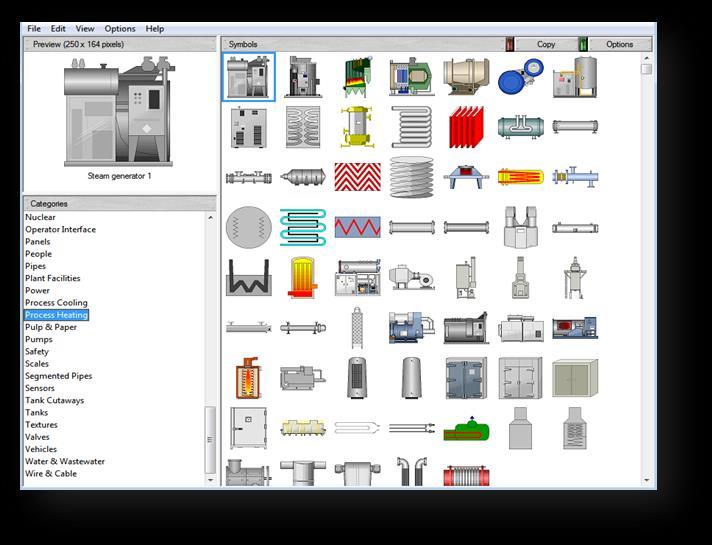
55 55 of 254

56 Libraries The Graphics Library comes with a number of ready-made graphic displays containing objects that you can use in other displays. There are many different library objects that you can use within your applications. Note: Any animation that has been attached to an object will be included with it when it is copied into a display. 56 of 254


57 Modifying an existing object on a graphic display Let s learn how to modify an object on a display that is already created for you. Note that a majority of the display is already complete for your convenience. 1. Double-click the cip_processsteps display to open it. Let us modify the Step 1: Adding H20 text of this display to read Step 1: Adding Water. 2. Select the text display Step 1: Adding H of 254

58 3. Double click the text display object to open the Text Properties window. You can also right click the text display object and select Properties. 4. Select the text H20 in replace it with Water. 5. Click OK to close the Text Properties window. Notice that the text in Step1 has changed from Step1: Adding H20 to Step1: Adding Water. We will now test the change we have made by using the Test Display button. Once a display has been created, it is good design practice to test the display. 6. Test the display by selecting Test Display button on the Graphics toolbar. Notice the text in the Text Display object changed from Step1: Adding H20 to Step1: Adding Water 7. Click the Edit Display button to get back to edit mode. Most objects that are created have different properties that you can modify to customize your application. Let s explore and modify a property of a Numeric Input object. 8. Notice that the cip_processsteps display has Numeric Input objects already created. Let s open one of them. 58 of 254


59 9. Open the properties of the Numeric Input object next to Step 2: Adding Chemicals by double-clicking the object. You might have to double click a few times to get to the Numeric Input object as the objects are grouped together You will notice the Numeric Input Properties window open up. 10. Observe the different properties available to modify under the General, Common and Connections tabs 11. Click on Display On-screen Keyboard checkbox to enable the Numeric keyboard to appear at runtime. This Display On-screen Keyboard property allows for a keyboard to pop up during runtime when a user interacts with the Numeric Input Object or a String Input object. Note that we are using a Numeric Input object and therefore a Numeric Keypad will open. If we have used a String Input object, a String Keypad will pop up at runtime. The input keypad is context sensitive. 59 of 254
 4. Tag description (HMI tags) 5.")
60 Numeric Keypad enhancements With FactoryTalk View Site Edition 8.1, the Numeric Input Keypad has been enhanced to give a user a modern look and feel. A sample screenshot is shown below. The enhanced Numeric Keypad now shows: 1. Current tag value 2. Current tag 3. Entry Min/Max (when configured) 4. Tag description (HMI tags) 5. Tag units (HMI tags) String Keypad Enhancements If a string input object was used, the enhanced String Keypad will pop up. The string keypad now shows: 1. Current tag value 2. Current tag 3. Tag description (HMI tags) 4. Tag units (HMI tags) 60 of 254

61 12. Click OK Let us test this change by using the Test Display feature. 13. Click on the Test Display button. 14. Click on the Numberic Input object next to Step 2: Adding Chemicals Notice the enhanced Keypad popup. 15. Type in a value between Notice the Current Value is This is the current value that is stored in the tag which will be changed to the value you entered once you click OK. You can also see the tag that is being changed at the top of the Keypad. Feel free to explore the different buttons on the keypad. 16. Click OK. 17. Click the Edit Display button to finish testing your display. 18. Save the changes you just made by selecting File Save. 61 of 254

62 Tooltips To provide information about a graphic object to an operator, you can add a tooltip to objects: Tooltips can be added to graphical objects Tooltips support embedded variables Language switching is supported on tooltip text By default, an object has no tooltip. If you add a tooltip, it displays at run time, when the operator positions the pointer over the object for a few seconds. Parameter Enhancements Added parameter enhancements provide support for embedded variables in tooltips and title bars. Literal numbers and strings can now be added into the embedded variable syntax. In this lab we will add a Numeric Input object to show a tooltip example. 1. In FactoryTalk View Studio, open the cip_processsteps display if it is not already open. 2. From the Objects menu, select Numeric and String Numeric Input. 62 of 254

63 3. Add the Numeric Input object in the display location shown below in red. 4. Select the Connections tab. 63 of 254
![5. Click on the ellipsis button to browse and add the Value tag under InstantFizz Data_Area Shortcut Online SodaCIPTanks RecoveredWater folder. {/Data_Area::[Shortcut]SodaCIPTanks.RecoveredWater.Value 6.](/docs-images/78/78516330/images/64-0.jpg "Click on the ellipses button to browse and add the Minimum tag: {/Data_Area:: [Shortcut]SodaCIPTanks.RecoveredWater.Minimum 7.")
64 5. Click on the ellipsis button to browse and add the Value tag under InstantFizz Data_Area Shortcut Online SodaCIPTanks RecoveredWater folder. {/Data_Area::[Shortcut]SodaCIPTanks.RecoveredWater.Value 6. Click on the ellipses button to browse and add the Minimum tag: {/Data_Area:: [Shortcut]SodaCIPTanks.RecoveredWater.Minimum 7. Click on the ellipses button to browse and add the Maximum tag: {/Data_Area:: [Shortcut]SodaCIPTanks.RecoveredWater.Maximum 8. Click OK to close. 9. Save the display. 10. Test the display by selecting Test Display button on the Graphics toolbar. We have specified the Minimum and Maximum values for the Numeric Input Object. Let s write a value into our object. This value has to be higher than the Minimum and lower than the Maximum values. 11. Type then press Enter. The object background will turn red indicating that the value enter is outside the valid minimum and maximum bounds. How will the operator know what the valid bounds are? Add a tooltip! Let s add a tooltip to the Numeric Input object. 64 of 254


65 12. Click the Edit Display button to get back to edit mode. 13. Double-click on the Numeric Input object to open up its properties. Or right-click and select Properties. 14. Select the Common tab. 15. Type Minimum: in the ToolTip text text box. 16. Click on Insert Variable and select Numeric to add a variable. 17. Browse to the {/Data_Area::[Shortcut]SodaCIPTanks. RecoveredWater.Minimum} tag. Click OK. 65 of 254
![18. Repeat steps 15-17 to add the Maximum: information as well. The Maximum tag to browse to is {/Data_Area::[Shortcut]SodaCIPTanks.RecoveredWater.Maximum}. 19. Click OK 20. Save the display. 21.](/docs-images/78/78516330/images/66-1.jpg "Test the display by selecting Test Display button on the Graphics toolbar. 22. Type 22000 then press Enter.")
66 18. Repeat steps to add the Maximum: information as well. The Maximum tag to browse to is {/Data_Area::[Shortcut]SodaCIPTanks.RecoveredWater.Maximum}. 19. Click OK 20. Save the display. 21. Test the display by selecting Test Display button on the Graphics toolbar. 22. Type then press Enter. Again, the object background will turn red indicating that the value enter is outside the valid minimum and maximum bounds. 23. Hover the mouse over the object and you should see our tooltip text indicating the proper value bounds. 66 of 254
67 Let s now observe how a change in value in a Numeric Input object appears in FactoryTalk Diagnostics. 1. In the cip_processsteps display notice the value in Step 2 2. Type 7000 into the Numeric Input object on Step 2 then press Enter. 3. Go to the bottom of the screen and notice the diagnostics message that is created showing the new value and the previous value. New in FactoryTalk View SE v8.0, when you change a Numeric Input or String Input value, the previous value and the new value being written are logged to FactoryTalk Diagnostics. In previous versions of SE, only the new value being written was logged. The benefits of this feature are: -Provides improved tracking of operator actions. -Improves support for 21 CFR Part 11 compliance. -Streamlines troubleshooting process 4. Click the Edit Display button to get back to edit mode. 5. Close the display cip_processsteps. 67 of 254

68 Configuring a button object to respond to commands FactoryTalk View commands allow you interact with and control application components. Most commands accept parameters for added precision and control. 1. You can set up keys and graphic objects to run commands at run time. For example, as the press, release, or repeat action when you assign touch animation to an object in a graphic display, or as the action for a button. 2. You can run commands from the HMI server s command line. 3. You can create a list of commands in a macro, and run the macro in places where the commands are required. 4. You can run commands at a particular event using an Event file. There are approximately 80 different commands. Use the Command Wizard for assistance with selecting and building commands. We will create a Button object with a display command. 1. In FactoryTalk View Studio, close all the currently open displays without saving. 2. Open the med_cip display. 3. Select the Button menu item from Objects Push button Button. 68 of 254


69 4. Draw the Button in the display as shown below where the red outlined box is shown: 5. In the Button Properties window that pops up, select the Action tab 6. Click on the ellipses button next to Press Action to open the Commands Wizard. 69 of 254


70 7. Select the Display command. You can either select All Commands and Macros and find the Display command alphabetically, or select Graphics Graphic Displays Navigation Display. The Command Wizard window can be resized by dragging the bottom right corner. This adds ability to see the list and the description of all command categories and associated commands without the need to use the scroll bars. 8. Click Next to continue. 9. Fill the display command information by selecting cip_processsteps from the File drop down list. If our application had more than one area we could choose to open a display from a different area. 10. Leave the optional selections blank and click Finish to complete. 70 of 254


71 11. Add a Button Caption by selecting the Up Appearance tab and typing CIP Process Steps in the Caption field. 12. Click OK to complete. The new button added should look as shown here. Resize the button if needed. 13. Save the display and then close it. 14. If it is not already open, launch the client window by clicking on Window Start > IF_Client_1280x1024.cli shortcut. 71 of 254
72 15. Select the CIP button in the navigation display. 16. Open the CIP Process Steps display. In the upper right corner of the CIP display, click on the newly added CIP Process Steps button. CIP Process Steps display will open! Using the Command Wizard we have created a button which when pressed opens another display. The Commands Wizard contains many more commands related to closing/opening displays, alarming, printing, languages, external applications and many others. Let s explore a different parameter for the Display command. 72 of 254
73 18. Close the CIP Process Steps display. 19. Notice the four valves on the CIP screen. These valves are buttons which will bring up a pop up display when clicked. This was implemented by using the Display command similar to the exercise we did in Steps Click on the first valve. Notice that the CIP Valves pop up display is displayed on top of the Valve button thereby hiding the button. 21. Close the CIP Valves pop up display. We can specify screen coordinates to position the display, but there is an easier way! We will modify a parameter of the Display command to bring up the display relative to the position of the calling button. Popup Position Relative to Calling Object With FactoryTalk View Site Edition 8.1, a HMI Developer can now specify the location of the popup to be relative to the calling object. This eliminates the need to specify screen coordinates. To implement relative positioning, simply use the /RP parameter with the Display command. 73 of 254


74 22. Minimize the IF_Client_1280x1024 client window. 23. Return to FactoryTalk View Studio and open the med_cip display if not already open. 24. Right click on the first of the four valves and select Object Explorer. We will learn more about the Object Explorer later. 25. Double click Button3 under Group 60 to open the Button Properties window 26. Select the Action tab 27. In the Release action section you will see the below configuration: Display CIP_Valves /T/Data_Area::[shortcut]CIPValve2.InAlarm,/Data_Area::[shortcut]Valve[2], /Data_Area::[shortcut]CIPValve2.Acked,/Data_Area::[shortcut]CIPAlarmTrigger[2],2 74 of 254
![28. Add the /RP parameter to the end of the line in the Release Action section as shown below: Display CIP_Valves /T/Data_Area::[shortcut]CIPValve2.](/docs-images/78/78516330/images/75-0.jpg "InAlarm,/Data_Area::[shortcut]Valve[2], /Data_Area::[shortcut]CIPValve2.Acked,/Data_Area::[shortcut]CIPAlarmTrigger[2],2 /RP Notice that there is a space between Trigger [2], 2 and /RP 29.")
75 28. Add the /RP parameter to the end of the line in the Release Action section as shown below: Display CIP_Valves /T/Data_Area::[shortcut]CIPValve2.InAlarm,/Data_Area::[shortcut]Valve[2], /Data_Area::[shortcut]CIPValve2.Acked,/Data_Area::[shortcut]CIPAlarmTrigger[2],2 /RP Notice that there is a space between Trigger [2], 2 and /RP 29. Click OK 30. Save the changes you made on the display by using the button 31. Close the Object Explorer 32. Return to the Client window and click on Overview to open the Plant Overview screen. 33. Click on the CIP button to open the CIP screen. 34. Click on the first valve and notice how the CIP Valves pop up display is now placed relative to the valve button s position and does not hide the valve button any more. 35. Close the CIP Valves pop up display and return to FactoryTalk View Studio. 75 of 254
76 Object Explorer, Animations and Expressions Animation is the ability to add logic to a graphic object so that some characteristic of the object will change when a tag value changes. For example, an object can be made to fill (up, down, left, or right) or change color in relation to a tag value. Expression is an expression is a mathematical or logical equation that returns a value. It can contain tag names, constants and mathematical, relational, logical and/or bitwise operators. A single tag name is often used for simple expressions. In the picture below, the animation dialog shows that expressions are used to animate objects. If there is a check mark in front of the animation type it means that the selected object is using that animation. If an animation type is not available for a selected object, the fields on that animation tab will be grayed out. In the example below, the Fill and Color animations are being used on the selected object. Selecting a new object while the Animation dialog is opened will update the Animation dialog for the object that was just selected. Let s also learn briefly what the Object Explorer is and how we can use it to look at Animations set on an object. 76 of 254

77 Object Explorer The Object Explorer provides a list of all the objects in the current graphic display, including those that are hidden by other objects. A group of objects has a plus sign in front of its name. Click this to expand the list of objects that make up the group. You can expand or collapse the whole list using the Expand and Collapse buttons. When you click an object in the display to select it, its corresponding entry in the Object Explorer is highlighted in gray. When you click an item in the Object Explorer, the object it corresponds to is selected. If an object is hidden by another, or is part of a group, when you select it in the Object Explorer the handles outlining the selected object are visible. Opening the Object Explorer 1. Return to FT View Studio and open the med_rapid_mix display. The Rapid Mix - Overview display will open. 2. Select the View Object Explorer menu item -orselect the Show/Hide Object Explorer button from the menu bar to show or hide it. The Object Explorer can be resized and moved. You can click on any of the objects listed, and you will notice that the objects will be highlighted in the display. 77 of 254

78 The Object Explorer is truly useful when you group items together and want to reference individual elements within that group. Grouping is useful when you have common objects that you want to move around or apply behaviors toward, for example, animation behavior. 78 of 254


79 Viewing groups and animation by using the object explorer 1. Select the Group4 group in the Object Explorer. 2. Click on the + next to the Group4 to expand the object group. 3. Right-click on the Water2 element within the Group4 group and select the Animation Fill context menu item. 79 of 254
80 4. The Animation dialog will appear and open on the Fill tab. The Fill animation expression has already been pre-entered for you. You can review and familiarize yourself with the Fill and other animation properties, such as Color. 5. Close the Animation window and the Object Explorer. 6. Return to the running client window and select the Rapid Mix button in the navigation display. 7. If the button at the top of the display says STOPPED then press it to start another cycle and watch the animation. If the button says RUNNING then the process is still working on the last processing cycle and is waiting for you to press the PRESS WHEN MANUAL ADD COMPLETED button to continue. 80 of 254

81 8. Watch the tank fill or empty (depending on where you are in the cycle). The water filling up in the tank or changing color happened as a result of the animation that you observed from the object explorer. 81 of 254

82 Enhanced Color Animation FactoryTalk View SE provides color/shading animation. In this section you will review the color animation capability. Gradient coloring allows a variable or static blending of two colors. Color Animation Demo Screen 1. From the FactoryTalk View Studio explorer, open the display sf_color_demo. 82 of 254


83 2. Select the Gradient colored Red Square, on the left. Right-click and select Animation Color to open the Animation dialog. Notice the Fill Style is set to Gradient for each configured state. 3. Left click the small red square to the right of Fill: to open the Gradient Fill dialog. Notice that this is for the state Value 1 of the animation. 83 of 254


84 The Colors slider adjusts the percentage of each color to be displayed. To select different colors Left click the Start or End Color and select a new color. The percentage of Gradient can be different for each value of the Color Animation. 4. When you are done looking at the Gradient Fill and Color animation configuration, click OK or Cancel to close the Gradient Fill dialog, Close to close the Animation dialog and select No when prompted to save changes. 5. Test run this screen by selecting Test Display button on the Graphics toolbar. Enter Values from 0 to 5 to see the different Percentage of Gradient fill. Remember to hit the Enter key after you type in a new value. 84 of 254

 0 state, the Original Fill Style is selected.")
85 6. Stop the running display by selecting Edit Display button on the Graphics toolbar 7. Right-click on the Boiler symbol under the middle Shaded area. Select Animation Color to open the Animation dialog. The Color tab shows the color animation configuration for the Boiler. Note that for the A) 0 state, the Original Fill Style is selected. This means that when the expression evaluates to a value of 0, the boiler graphic will be displayed in its original color. Fill Styles include Original, Shaded, Solid and Gradient. 85 of 254
 has a Fill Style of Original.")
86 An HMI memory tag, SF_Test, has been configured for this example. When Fill Style is set to Original, the color indicators reflect this selection by displaying the symbol. 8. Scroll through the A to P thresholds on the left.. This graphic symbol has been configured for a color selection and value for each threshold. Threshold A (Value=0) has a Fill Style of Original. The remaining thresholds (B to P) are configured for the Shaded Fill Style. Thresholds K, L, and M are configured to blink the Fill Color. 9. Click Close to close the Animation dialog. 10. Select No if asked to save changes to the Animation dialog. 11. Right-Click on the Boiler under the Gradient Column, and Select the Object Explorer. Expand Group20 and right Click on PolyLine91. Select Properties. The Polyline Back Style is set to Gradient. Left Click on the Back Color 86 of 254


87 12. Click OK to close the Gradient Fill window 13. Click OK to close the Polyline Properties Window 14. The machines below the Boiler have Polylines with their back Styles set to Gradient and the Gradient fill properties set to enhance the coloring of the machines. Explore each machine, setting the Back Style and Gradient Fill coloring percentage and shading direction. The Solid Column has Fill Style set to Solid The Gradient Column has Gradient selected for some of the Back Style Properties. 87 of 254
.")

88 15. Test run this screen by selecting the Test Display button on the Graphics toolbar. The screen will appear like this when running: The starting value is zero (0). If the value shown in the indicator is not zero, then click RESET to set it back to zero (0). Each graphic symbol on this display is configured to maintain the original library color at value zero (0). 16. To show the color changes on each symbol, increment the analog value by selecting the Ramp Up button. The value will increase by 1 and each symbol will change to the next color. Notice that even with the color change, the shading of the objects in the middle column has been maintained. When the value is greater than zero, notice the difference between the Solid, Shaded and Gradient Fill Styles. 88 of 254
89 17. Ramp the value to 11 and 12 to see the object blink between two colors. 18. Stop the running display by selecting Edit Display 19. Close the display without saving. 89 of 254

90 Local Messages Use local message displays to provide an operator with information about a process, or about what to do next, at run time. For example, the med_rapid_mix display contains a Local Message object that gives the operators instructions on what the current step is in the mixing tank. 1. In the running client window, select the Overview button in the navigation display in order to close the Rapid Mix display. 2. Return to FactoryTalk View Studio. Let s review the rapidmix Local Message file that has been pre-created for you. Open this file: 90 of 254


91 3. Local Message editors consist of Trigger Value and Message columns. When the value of the Local Message tag equals the Trigger Value, the corresponding Message will be displayed. For example, if the tag value is equal to 6, the message STEP 6: Initiating CIP Clean will be displayed. 4. Click Close. 5. In order to view the messages on a display at run-time, a Local Message object needs to be added. Open the med_rapid_mix display. 6. Add the Local Message Display to med_rapid_mix by selecting the Local Message Display object from Objects Advanced menu. 91 of 254


92 7. Draw the Local Message Display object as shown. 8. We will modify some properties of the message text, such as font and color. On the Properties dialog that opens up, change the Font Size to of 254


93 We would like this Local Message Display to display messages from the RapidMix Local Message File. The messages will be triggered by the /Data_Area::[Shortcut]MixSteps tag 9. Click on the ellipses button below Message File to browse the Local Message File. Select rapidmix then click OK to close. 10. Select the Connections tab and browse to the /Data_Area::[Shortcut]MixSteps tag. In the tag browser expand Shortcut, select Online then on the right, select the MixSteps tag. The value of this tag will determine which message will be displayed. 93 of 254

94 11. Click OK to close. 12. Save and close the display. Let s view the Local Messages in action 13. Return to the running client window and select the Rapid Mix button in the navigation display. 14. If the button at the top of the display says STOPPED then press it to start another cycle and watch the Local Message Object display different messages depending on what process step is being executed. If the button says RUNNING then the process is still working on the last processing cycle and is waiting for you to press the PRESS WHEN MANUAL ADD COMPLETED button to continue. 15. Follow the Local Message messages as they change. 94 of 254

95 16. Minimize the running client window and return to FactoryTalk View Studio. Let s now explore the configuration behind the Manual Add button that was used above in the Rapid Mix process. 17. Return to FT View Studio and double click on the Manual Add button within the Rapid Mix display. 18. Once the Button Properties window is open, click on the Disabled Appearance tab. The expression defined indicates that the button will only become enabled once Step 3 of the process has been reached as indicated by the MixSteps tag. Button objects now have the ability to use a tag name or an expression to determine whether the state of the button should be enabled or disabled. The appearance of the disabled state is configurable with an automatic grayscale option or the use of image references. 95 of 254


96 We also want to verify that a user is a part of a specific security user group before they can gain access to this button. Let s add to the button state expression to accomplish this. 19. Click on the Expression button to edit the button state expression. 20. Click at the end of the expression to add an and so that your expression now looks like the following: 21. Click the Functions button to bring up the list of function categories. 22. Select Security then CurrentUserHasGroup(user group name) to add this function to the expression and click OK. 96 of 254
97 The CurrentUserHasGroup() security function gives the ability to check whether the current user has been assigned to a particular FactoryTalk user group. FactoryTalk View SE v8.0 also introduced the CurrentUserGroups() security function that return the FactoryTalk user group list of which the current user is a member. This function is available in VBA only. 23. Verify that the CurrentUserHasGroup( ) function has now been added to the expression. 24. An Operators group has already been created within the FactoryTalk Directory. This is the group we want a user to be a part of before they will have access to the Manual Add button. To specify this group within the function, type Operators within double quotes. The expression should now look like the following: 25. Click OK twice to save the changes to the Expression Editor and the Button Properties. 26. Save the changes to the Rapid Mix display. 27. Return to the running client window and navigate away from the Rapid Mix display. 28. Once again select the Rapid Mix button in the navigation bar so that we can load the display with our changes. 29. If the button at the top of the display says STOPPED then press it to start another cycle and watch the Local Message Object display different messages depending on what process step is being executed. 97 of 254

98 30. Follow the Local Message messages as they change. Once Step 3 has been reached we had previously seen that the button would become enabled. However, we have since added the criteria of the Operators user group to which Labuser is not a part of and the button remains disabled. The currently logged in user is indicated in the upper right hand corner of the display. 31. We will now log in Operator1 who is a member of the Operators group. To log this user in click on the More menu and select Security. 98 of 254


99 32. Select the Log In button and enter the credentials Operator1 for both user name and password. Note that the password is case sensitive. 33. Click OK and close the Security display. 34. We have now logged in a user that is part of the Operators user group. Notice that the button has changed from disabled to enabled because the button state expression is now evaluating to true. With the CurrentUserHasGroup() security function now a part of the expression, click the enabled button and watch the Local Messages as the process completes. 99 of 254
100 35. We will now log back in as Labuser. To log this user in click on More Security. 36. Select the Log In button and enter the credentials Labuser for user name and rockwell as the password. Note that the password is case sensitive. 37. Click OK and close the Security display. 38. Minimize the running client window 39. Return to the FactoryTalk View Studio InstantFizz application. We will now remove the CurrentUserHasGroup() function from the expression under Disabled Appearance. 40. From the med_rapid_mix display, double click the Manual Add button to open the button properties. 41. Once the Button Properties window is open, click on the Disabled Appearance tab. 42. Click on the Expression button to edit the button state expression. 43. Modify the expression as shown in the screenshot below: 100 of 254

101 44. Click OK twice to save the changes to the Expression Editor and the Button Properties. 45. Save the changes to the Rapid Mix display. 101 of 254

102 Creating a simple Parameter file When you create a graphic display that uses tag placeholders, you can specify a parameter file that will supply tag or folder names, or parts of tag names, for the tag placeholders at run time. This allows you to use different sets of tags with a single graphic display. Let us create a simple parameter file with two parameters. 1. Right click on the Parameters editor in the application tree and select New menu. We will be creating two parameters as shown below: 102 of 254

103 2. Type #1= in the first line 3. Double click in the white space area next to #1=. This will launch the Tag Browser FactoryTalk View supports the ability to launch the Tag Browser from within the Parameters editor. This makes it easy to search and add the tags of your choice without having to rely on your memory to add the tag name. 4. Select the BlueBerry_Amt tag from InstantFizz HMI_Area in the Tag Browser and press OK. You have just created a single Parameter definition. Notice how the tag path is added to the Parameter definition 5. Now repeat Steps 2-4 to add another parameter with the associated tag Kiwi_Amt. The parameter file should look like this: 103 of 254
104 6. Close the parameter file that you just created and save it as test_parameter when prompted to save. Let us now test run this parameter definitions that we created in a display. We will create a new display for this section. 7. Create a new display by right-clicking on Display New 8. Create a numeric display object by selecting Objects Numeric and String Numeric Display 9. Click on the white space on your new display and draw the Numeric display object. The Numeric Display Properties window appears. 10. In the Expressions editor box, type #1 Recall that #1 is associated to BlueBerry_Amt in our parameter definition. 11. Click OK to close the Numeric Display Properties window. 12. Create a second numeric display object by selecting Objects Numeric and String Numeric Display 13. Click on the white space on your new display and draw the Numeric display object. The Numeric Display Properties window appears. 14. In the Expressions editor box, type #2. Recall that #2 is associated to Kiw_Amt in our parameter definition. 104 of 254
105 15. Click OK to close the Numeric Display Properties window. Your display will now look like this. 16. Test run this display by using the Test Display button. 17. The parameterized screen testing window appears. New in FactoryTalk View 8.1, HMI Developers can now use Test Display on screens with parameters. Users can specify individual tags in the Parameter List or select a parameter file. This avoids the need to launch the FactoryTalk View client file to simply test the paramaters. We already have a parameter file! Let s select the parameter file that we created. 105 of 254


106 18. Click the Browse button. The Component Browser window opens. 19. The test_parameter parameter file that we had created is selected by default for you. 106 of 254
107 20. Select OK. 21. Select OK in the Parameterized screen Test Display window. What did you see on the display while testing? The tags values for BlueBerry_Amt and Kiwi_Amt are passed to the parameters #1 and #2 that you see while testing the display. A sample Notice how easy it was to create the parameter file with the parameter definitions by just browsing to the Tag Browser. We also tested the defined parameters from within the Test Display environment without having to launch a runtime client file. 18. Close the Untitled display and select No when asked to save changes. 107 of 254

108 Digit Grouping The Numeric Display graphic object can show the digit grouping of the tag value at runtime. The digits are divided in groups of three by the Windows digit grouping symbol. The digit grouping symbol uses the numeric format of the current runtime language. The format can be configured in the Windows Region and Language settings of Control Panel. This improves readability for the user at runtime. Let s explore this feature. 1. Open the languages display in FactoryTalk View Studio. 2. Select the Objects Numeric and String Numeric Display menu. 3. On the blank area at the bottom of the display, click and drag the mouse to draw the Numeric Display object and then release the mouse button to create the object. The Numeric Display properties dialog will appear. 108 of 254

109 4. Click on the Tags button to open the Tag Browser. 5. Select the HMI_Area item on the left side to display the HMI tags on the right side. 6. Select the DigitGrouping tag on the right side and press OK. 109 of 254
110 7. Set the Field Length to Check the Show Digit Grouping option and press OK to save the changes. We have just created a Numeric Display object that is using Digit Grouping. Now let s duplicate this object and turn off the Digit Grouping so that you can see the difference. 110 of 254

111 9. Right-click the Numeric Display object and select the Duplicate menu item. (Alternatively, you could have selected the object and pressed Ctrl-D to duplicate it.) 10. Click the duplicated object and drag it below the original object. 11. Double-click the duplicated object to open the Numeric Display Properties dialog. 12. Uncheck the Show Digit Grouping option and press OK to save the changes. Now we are going to need a Numeric Input object so that we can modify the value of the DigitGrouping tag. 111 of 254

112 13. Select the Objects Numeric and String Numeric Input menu. 14. To the right of the Numeric Display object, click and drag the mouse to draw the Numeric Input object and then release the mouse button to create the object. The Numeric Input properties dialog will appear. 15. Set the Field Length to Select the Connections tab. 17. Press the button under the Tag column for the Value connection and browse and select the DigitGrouping tag like you did for the Numeric Display object. 112 of 254


113 18. Press OK to save the dialog changes. 19. Close and save the languages display. Let s see how this Digit Grouping feature looks at runtime. 20. Switch to the running client window and click on the click the MORE button on the right side and then the LANGUAGES button in the navigation display. 21. In the Numeric Input object, enter the number and press the ENTER key. Notice that the Numeric Display object with Digit Grouping has commas to separate the digits. Also notice that the Numeric Display object without Digit Grouping has no separator character in the digits. 113 of 254


114 22. Close the InstantFizz client application by clicking on More Shutdown 23. Select YES/EXIT at the following prompt: Now, let s see how switching the language affects the Digit Grouping display. We will add two languages French and German to the FactoryTalk View application, InstantFizz to see how Digit Grouping varies when different languages are used. 24. Return to the InstantFizz application in FactoryTalk View Studio 25. Select Tools Languages 114 of 254
.")
115 26. In the Language Confirmation dialog window, click Add. 27. In the Add Language window select French(France). 28. Click OK. 29. The Language Confirmation window should look like this: 30. Repeat steps to add another language German (Germany). The Language Confirmation window should look like this: 115 of 254

116 31. Click OK to close the Language Confirmation window. 32. Launch the InstantFizz runtime client application by click on the Launch SE Client button. 32. Select the IF_Client_1280X1024.cli and click on Run. 33. Click on the More button Languages. 34. Press the French button to switch the application to use the French language. Notice that the Numeric Display object with Digit Grouping has spaces to separate the digits. This is the French standard. 35. Press the German button (third button from left) to switch the application to use the German language. Notice that the Numeric Display object with Digit Grouping has periods to separate the digits. This is the German standard. 36. Press the English button (left most button) to switch back to English and then close the display. 116 of 254

117 37. Minimize the running client window. Now, we re going to see how the different languages define the different standards for Digit Grouping and what character is used to separate the digits. This is defined in the Windows operating system. 38. From the Windows START menu, select the Control Panel Region and Language option. This will open the region and language options for English (United States). 39. Click on the Additional settings button. 117 of 254

118 This will display the Digit Grouping format and the Digit Grouping symbol used to separate the digits. 40. Press Cancel to close the dialog. 41. Explore the Digit Grouping for other languages by selecting a different language in the Format list at the top of the dialog and then opening the Additional settings button again. 118 of 254

119 42. When you are done exploring, press Cancel on both these dialogs so that the default language for the computer remains at English. 43. Close the Control Panel Region and Language window. Congratulations! You have completed Section 5! FactoryTalk View Site Edition - Building Applications Lab 8.0 / 8.1 Content Section 1: Experience FactoryTalk View SE run time (10 minutes) Section 2: Working with the InstantFizz Application (5 minutes) Section 3: Creating and testing Tags (10 minutes) Section 4: Testing displays and creating a runtime client (10 minutes) Section 5: Graphic displays, objects, animations (30 minutes) Section 6: Working with Global Objects (30 minutes) Section 7: Data logging and Trending (15 minutes) Section 8: FactoryTalk Alarms and Events (30 minutes) Section 9: Language Switching (15 minutes) Section 10: FactoryTalk View Application Documenter (5 minutes) Section 11: Introduction to FactoryTalk ViewPoint (20 minutes) 119 of 254
120 Section 6: Working with Global Objects (30 minutes) About this section In this section, you will learn the following about Global Objects: Create reference objects in a display, and view the display Using Global Object Parameters Testing Global Object Parameter Values in FactoryTalk View Studio Using Tag substitution on Global Objects Modifying a global object, and view the changes in a display Read about Global Objects FactoryTalk View global objects allow you to link the appearance and behavior of one graphic object to multiple references of that object in the same application. Global objects are created on global object displays. In FactoryTalk View Studio, you create global object displays in the Global Objects folder, the same way you create standard graphic displays in the Displays folder. Changes you make to the base object are reflected in all of the reference objects linked to it the next time a display containing the reference objects are opened, or refreshed by closing and reopening them. Global Object Parameters Global object parameters let you customize each reference global object instance with a specific tag(s) for that instance without having to break the link to the base object's tags and expressions. This means each reference object can have a unique data source(s) and still be able to be updated with changes to other aspects of the base global object. Parameter passing is dynamic, meaning it happens at runtime on the client. Global object parameters give you an alternative way of using parameter passing at design time. Create reference objects In this section of the lab, you will use a pre-created global object and add a reference object on a display. You will use the parameter values to specify which tags you want to view and animate. 120 of 254


121 Pre-created Global Object displays 1. In FactoryTalk View Studio, open the cipcomponents global object. You will see some of the global objects that are used in this application: 121 of 254

122 2. Right-click on the left gray tank global object and select Global Object Parameter Definitions 3. Review the Global Object Parameter Definitions for the tank global object. Global object parameters are defined in base objects in global object displays. They let you customize each reference global object instance with a specific tag(s) for that instance without having to break the link to the base object's tags and expressions. When you copy a global object from a global object display onto a standard display from the Graphics folder, you can assign values to the global parameters in the resulting reference object. 122 of 254

123 We have defined parameters #1 - #5 and provided a description for each. Click Cancel to close. The placeholder parameters can be used in any object contained on the global object display but the Global Object Parameter Definitions are assigned at the top level group. 123 of 254
 to select, drag and drop it on the tank location of the med_cip display.")
124 4. Open the med_cip display. 5. Create a reference object on the med_cip display single-click on the tank global object (in cipcomponents) to select, drag and drop it on the tank location of the med_cip display. You may need to bring the cipcomponents display to the front (by double-clicking on the cipcomponents under Global Objects again) so that it is not covered by the med_cip display. Drag and drop the tank from the cipcomponents Global Object onto the med_cip display. Position the object in the location shown. 124 of 254

125 6. Close the cipcomponents global object. Don t save it if prompted. 7. Open the Global Object Parameters dialog on the reference object by right-clicking on the reference object and select the Global Object Parameter Values context menu item. 125 of 254

126 The Global Object Parameter Values dialog is opened. Notice that there is a description for the #1 to #5 parameters. You will be browsing for several tags. 126 of 254
![8. Assign tags for #1 - click on the button under the Tag column for #1. When the Tab Browser opens navigate to {/Data_Area::[Shortcut]CIPFilling[3]} 9. Click the OK button. 10.](/docs-images/78/78516330/images/127-0.jpg "Repeat the above step for #2 - #5 using the tags below: Name Tag Description #2 {/Data_Area::[Shortcut]CIPTimer[3].ACC} The value of the liquid in the tank while the tank is filling.")
127 8. Assign tags for #1 - click on the button under the Tag column for #1. When the Tab Browser opens navigate to {/Data_Area::[Shortcut]CIPFilling[3]} 9. Click the OK button. 10. Repeat the above step for #2 - #5 using the tags below: Name Tag Description #2 {/Data_Area::[Shortcut]CIPTimer[3].ACC} The value of the liquid in the tank while the tank is filling. #3 {/Data_Area::[Shortcut]Program:Main.TempCalc[3]} The value of the liquid in the tank while the tank is emptying #4 {/Data_Area::[Shortcut]CIPTankColour[3]} Colour of the tank #5 {/Data_Area::[Shortcut]CIPActive} CIP active? 127 of 254

128 The completed Global Object Parameter Values dialog should look as follows. 11. Click the OK button on the Global Object Parameter Values dialog. Test the display Now you will test out the Global Object Parameter Values in FactoryTalk View Studio. New in FactoryTalk View SE 8.1 is the ability to test your parameters in FactoryTalk View Studio. This saves you the trouble of having to start the FactoryTalk View SE Client in order to test out your parameters. This new feature includes the ability to test out regular Parameters (e.g. #1), Parameter Files and Global Object Parameter values in FactoryTalk View Studio. 1. Test the display by selecting Test Display button on the Graphics toolbar. 2. To see the animation in action, press the CIP Repeat Cycle button. What happens? You should see values and animations for all tanks. Each one of the tanks is a reference object to the tank global object. We have assigned unique Global Object Parameter Values for each tank, resulting in different colors, fill values and data for every tank. 3. Click the Edit Display button on the Graphics toolbar to get back to edit mode. 128 of 254

129 Tag Substitution Reference objects created with global object parameters support the Tag Substitution feature. This can be used as an alternative method to creating instances of the same reference objects but with different parameters. In the previous exercise you created a reference object by copying a base global object from a global object display onto a standard display and then edited its parameters. In this exercise you will achieve the same result by using an alternative method copying an existing reference object and modifying its parameters using the Tag Substitution feature. 1. In FactoryTalk View Studio, open the med_cip display. 2. Delete the reference object instance you created in the previous exercise. It is the second tank from the left above the Sanitizer text. 129 of 254
 by selecting it with the mouse and then right-clicking and selecting the Duplicate menu item.")
130 3. Copy the leftmost tank reference object (i.e. the tank object above the Chemicals text.) by selecting it with the mouse and then right-clicking and selecting the Duplicate menu item. 130 of 254

131 4. Drag the copy of the Tank object and drop it in the empty tank location. 131 of 254


132 5. With the copy of the reference object still selected, on the main menu click Edit > Tag Substitution or press Ctrl-R on the keyboard or right-click and select Tag Substitution menu. The Tag Substitution dialog is now opened. 6. In the Search for: field type 2 and in the Replace with: field type 3. Clear Confirm replacements check-box. By replacing number 2 with number 3 you are associating a copied referenced object with a different group of pre-existing data items. Make sure you are working with the newly copied Tank object. 132 of 254

133 7. Click Replace to replace all instances at once. Four tag instances will be substituted. 8. Click OK to close the Tag Substitution Complete dialog window. Notice how in this exercise you didn t have to open Global Object Parameter Editor to edit and modify parameters associated with the new tank reference object. All the parameters were modified through Tag Substitution. Test the display Now you will test out the Global Object Parameter Values in FactoryTalk View Studio. 1. Test the display by selecting Test Display button on the Graphics toolbar. 2. To see the animation in action, press the CIP Repeat Cycle button. What happens? You should see values and animations for all tanks. Each one of the tanks is a reference object to the tank global object. We have assigned unique Global Object Parameter Values for each tank, resulting in different colors, fill values and data for every tank. 3. Click the Edit Display button on the Graphics toolbar to get back to edit mode. 4. Close and save the med_cip display. 133 of 254

134 Modifying Global Objects What happens when you think you have your application all done and then you get a change request? The change could be adding a new item to a display or changing colors on an animation. Global objects allow you to make the change in the base object and the reference objects will inherit that change. This makes maintaining your application a lot easier. You will be modifying the cipcomponents Global Object. Modify text You will change the color of text that is used several times in the med_cip display. Instead of changing the color property several times for each reference, you will only change it once in the base object and every reference object will reflect that change. 1. In FactoryTalk View Studio, open the cipcomponents Global Object. 2. Open the Object Explorer by selecting the View > Object Explorer menu item. 3. Find the object Text1 object in the Object Explorer and select it. It is at the bottom of the window inside the Group3 group. 134 of 254

135 4. Double-click on Text1 in the Object Explorer to open the Text Properties dialog and change the Fore color property to red. Change the Fore color of the text to RED. 5. Click the OK button. 6. Close and save the cipcomponents Global Object. 7. In FactoryTalk View SE Client, if the CIP display is already open, we need to re-open it. To do this, click the Overview button and then click the CIP button from the navigation bar. If the CIP display is not already open, then just click the CIP button from the navigation bar. Notice the four reference objects have been changed: So you made a change in 1 place, the base object and the 4 reference objects now reflect the change. 135 of 254
136 Congratulations! You have completed Section 6! FactoryTalk View Site Edition - Building Applications Lab 8.0 / 8.1 Content Section 1: Experience FactoryTalk View SE run time (10 minutes) Section 2: Working with the InstantFizz Application (5 minutes) Section 3: Creating and testing Tags (10 minutes) Section 4: Testing displays and creating a runtime client (10 minutes) Section 5: Graphic displays, objects, animations (30 minutes) Section 6: Working with Global Objects (30 minutes) Section 7: Data logging and Trending (15 minutes) Section 8: FactoryTalk Alarms and Events (30 minutes) Section 9: Language Switching (15 minutes) Section 10: FactoryTalk View Application Documenter (5 minutes) Section 11: Introduction to FactoryTalk ViewPoint (20 minutes) 136 of 254
137 Section 7: Data logging and trending (15 minutes) About this section In this section, you will learn about: Runtime Exploration o Data Logging o Trending Configuration Exploration o Historical Trending o Runtime Trending o Data Log Models Configuring Methods using the Invoke command You will be using the cip_sensortrend display and CIP data log model. Runtime exploration Data logging Data logging is a FactoryTalk View component that collects and stores tag values. You specify which tag values to collect, when to collect them, and where to store them by defining a data log model. The HMI tag database does not store actual tag values; it only defines which values are to be collected. The values themselves are stored on a given HMI server. When the HMI server is turned off, the value table is cleared (excluding retentive tags). To have a permanent record of tag values, log them to the data log file on disk. Remember: controller tags will keep their value when an HMI server is powered down because they re located within the controller; they re not HMI (or memory) tags stored on the server itself. To log tag values to disk, you create a data log model and specify the tags that are to be logged. This is done in the Data Log Model editor. The values can also be logged to an ODBC-compliant database. An application can have up to 20 data log models running at a time. The maximum number of tags that can be logged by one data log model is 10,000. Trending A trend is a visual representation, or chart, of current or historical tag values. A trend provides operators with a way of tracking plant activity as it is happening. The trend object displays real-time data and historical data from the FactoryTalk View Site Edition data logs. Pens on the run-time chart represent data from the tags and expressions that you add to the trend object. The trend object provides extensive, flexible run-time control. You can add pens, toggle between isolated and non-isolated graphing, specify unique line settings, plot one variable against another in XY plots, and print chart data. There are two different types of Trending: Historical Trending Historical Trending is when a trend polls data from a data log that is previously configured. This will allow the user to browse through a timeline to look at the data over a given period of time. 137 of 254

138 Runtime trending A Runtime trend displays data trends directly from the processor. The trend will start trending its runtime data from the time it s first loaded on the display. Configuration exploration Data log models 1. Double-click the cip datalog model to open. The CIP Data Log Model dialog opens to the Setup tab. A pre-configured System DSN pointing to a database that is called ODBC_InstantFizz is set up. For this example the ODBC data source points to Microsoft Access. An alternative could be SQL Server. 138 of 254
 called ODBC_InstantFizz that points to a Microsoft Access database called ODBC_InstantFizz.")
139 You can set up logging to a file set or to log to any database that you can connect to with ODBC. The data log model can be configured to be stored as a file set or an ODBC database. Notice that this data model is being stored in an ODBC database. There is a System Data Source Name (DSN) called ODBC_InstantFizz that points to a Microsoft Access database called ODBC_InstantFizz. An ODBC System DSN stores information about how to connect to the indicated data pointer. If you would like to see how the System DSN was configured, double click C:\Windows\SysWOW64\ odbcad32.exe. The ODBC Date Source Administrator window will open. Select the System DSN tab. Double click the ODBC_InstantFizz System Data source to see how the System DSN was setup. 2. Click the Create Tables button. You should get a FactoryTalk View Datalog Editor message saying ODBC tables were successfully created. Click the OK button. 3. Click on the Paths tab. This Paths tab is used to set the file location of the data logs. This is useful if you have a distributed network set up; you will want to store the logs to one common location instead of on each individual HMI server on the network. 139 of 254
 you will be able to see the historical data in the trend display because of the secondary Backup Path. 4. Click the File Management tab.")
140 Notice that the Enable ODBC Backup Path was selected and a logging path was specified. If the connection to the ODBC database fails (Microsoft Access) you will be able to see the historical data in the trend display because of the secondary Backup Path. 4. Click the File Management tab. This configuration tab is used to configure how long you want to keep logging to individual files until you either create a new file or delete older files. 140 of 254

141 5. Click the Log Triggers tab. This configuration tab is used to decide how often and based upon what event the log should be updated. Notice that the trigger for logging is Periodic and we are logging periodically every 3 seconds. The data log can be configured to log Periodically, On Change, or On Demand. Periodic To log tag values periodically, select Periodic, then type a time in the Interval field and select a time unit to specify how often tag values will be logged. All tags will be logged each time this interval expires. On Change On Change logging only logs tags whose values have changed. Use the On Change trigger to log tag values once a certain percentage of change in the value has occurred. The percentage is based on the tag's minimum and maximum (or High EU and Low EU) values. For example, specifying 10 means a tag's value must change by 10 percent to be logged. This applies to analog HMI tags only. For data server tags and digital and string HMI tags, which do not have minimum/maximum properties, every change is logged. On Demand Choose On Demand as the trigger, to log data only when the FactoryTalk View command DataLogSnapshot is issued. This command can be given anywhere that other FactoryTalk View commands and macros can be. For example, it could be typed in the command line, or specified as the action for an event. If you specify Periodic or On Change, you can still use on demand logging whenever it is appropriate. 141 of 254
142 6. Click the Tags in Model tab. This configuration tab is used to select what information is logged. You can add or remove different tags from this menu using the tag browser. Notice 5 tags have been added to the model. 7. Click the Cancel button to close the CIP Data Log Model dialog. 142 of 254

143 Configuring trends Do not add a new trend or change this one. You can do so at the end of this section. 1. From the Explorer, double-click on the cip_sensortrend display to open it. A new Trend object can be created by selecting the Objects Advanced Trend menu item or by selecting the Trend button on the menu bar 2. Double-click on the grid of the existing Trend object on the display. The Trend Properties dialog will open. Let s get familiar with the trend properties and capabilities. 143 of 254

144 3. Click on the General tab. The General tab contains several configurable properties. The Chart Style determines the plotting style of the chart. A trend chart can either plot values against time or against a selected pen. 144 of 254
 button. The Configure Tags dialog opened.")
145 4. Click the Pens tab. Notice that the Model column has CIP which is the data model that was created. These pens were added by setting the Pen Source to Data Log Model and then selecting the Add Pen(s) button. The Configure Tags dialog opened. The Add All button was selected to add all the tags. Then the OK was clicked to accept the changes. 145 of 254

146 5. Click on the X-Axis tab. Use this tab to set up the time range and display options for the chart's run-time horizontal axis. The Time Span controls the amount of data that displays on the run-time chart. For a standard line chart, the time span controls the chart's horizontal scale. For an XY plot, the Min and Max properties (set up on the Pens tab) of the selected pen control the horizontal scale, and the time span controls the number of data points plotted. 146 of 254

147 6. Click on the Y-Axis. Use this tab to set up the minimum/maximum value options, display options, and scale options for the chart's run-time vertical axis. For example, Isolated graphing places each pen in a separate band of the chart. To allow pens to overlap, you would need to clear the check box. 147 of 254

148 7. Click on the Overlays tab. With the trend object, you can capture and save a snapshot of graphed data at run-time and then layer that saved data over current data in a trend. This feature allows you to overlay and compare historical data with current data or any multiple sets of data. 148 of 254

149 8. Click on the Template tab. Use this tab to save the settings for the current trend as a template, to load another template for the current trend to use, or to delete a template. The settings that are saved for the template are those from the General, Display, Pens, and X and Y Axis tabs. A template can be applied to all trends in an application to create a consistent appearance. You can load templates during design time and runtime. We will import several pre-created templates into the application. But first we will complete reviewing the Trend properties and capabilities. 149 of 254


150 9. Click on the Runtime tab. Use this tab to determine which trend options are available to operators at run time. To prevent operators from changing these options, the Runtime tab is not available at run time. 10. Click the Cancel button on the Trend Properties dialog to close the dialog. Notice that we have a few Trend Templates already added to the project. 11. In the cip_sensortrend display, right-click on the Start group object to display the context menu and then select the Animation Touch menu to open the Animation properties. 150 of 254
151 12. The Release Action command DataLogOn cip starts the data logging for the model. The Datalogon command can be placed in a start-up macro as well. When the client is launched, the datalogging is started automatically from the start-up macro. 13. Notice the Confirm Action check box is checked. You can choose to show a confirmation popup dialog box and configure the appearance when executing commands or actions on buttons, numeric inputs, string inputs, or objects with touch animation. The benefits of using this feature: Enable operations to confirm they want to take requested action before it occurs. Remove the need to use a display graphic to perform this native action. 151 of 254

152 14. Click the Configure Button. The Confirmation configuration dialog box opens up. Notice that there are several properties here that can be customized in this dialog box. Title Bar - Select this check box to show the title bar of the confirmation dialog box. You can enter up to 255 characters. Insert Variable - Adds an embedded variable to the title bar. Click Insert Variable and then select the type of variable to be inserted in the caption. In the Variable dialog box, specify the details. After you have set up the embedded variable, the syntax appears in the Title Bar field. Window position - Select a position where the confirmation dialog box will be shown. Caption - Enter the message that will be shown in the confirmation dialog box. If you have added an embedded variable to the caption, the embedded variable syntax appears in the Caption field, but the text of the variable appears on the dialog box. Insert Variable - Adds an embedded variable to the message. Click Insert Variable and then select the type of variable to be inserted in the caption. In the Variable dialog box, specify the details. After you have set up the embedded variable, the syntax appears in the Caption field. Font - Select a font for the message, or click the browse button (...) to open the standard font dialog box that lets you select a font and specify how it is to look (except for font color). Size - Select a font size from the list. Image settings - You can choose a pattern and color for the confirmation dialog box. You can also import a bitmap or icon to be displayed on the dialog box. 152 of 254
153 No image - Select this if no bitmap, jpeg, png, or icon is to be displayed on the dialog box. Use image reference - Select this to use an image from the current HMI project. Image - Enter the name of the image file or click the browse button (...) to select an image to reference using the Image Browser. If you add an image to the Image Browser, it is also added to the Images folder in the Explorer. Import file - Select this and then click Import to locate and select a bitmap or icon to display on the conformation dialog box. The imported graphic is placed in the center of the dialog box and saved with it. The caption is displayed on top of the imported graphic. This does not add the image to the Images folder in the Explorer. Scale image - Select this check box to scale the image to fit within the dimensions of the dialog box. This applies to both referenced and imported images. The recommended dimensions are 48 x 48 pixels. Button Settings - Select buttons that will be shown in the confirmation dialog box, including OK and Cancel, OK only, Yes and No, and Yes only. 15. Notice the Caption property that has a custom text that will be displayed in a dialog box at runtime in the client to the user with the buttons OK and Cancel that are clickable. 16. Click the Cancel button to close the Confirmation properties. 17. In the Animation properties window, notice that the Touch Style is specified as Irregular. Since we are using a circular object to execute our DataLogOn command with touch animation, we would like for the touch area to be circular as well. An irregular touch style is selected when the object outline is the desired touch area versus the default rectangular bounding box. 18. Click the Close button to close the Animation properties. 153 of 254

154 We will now configure the Confirmation pop up box for the Stop button. 19. Right-click on the Stop group object and navigate to Animation Touch menu to open the Animation properties. 20. Check the Confirm Action checkbox. 21. Click the Configure button. 22. Configure the Confirmation window as shown below and Click OK to close the dialog. 23. Click Apply and then Close to save the animation and close the animation dialog. 24. Close the cip_sensortrend display. When prompted to save changes, select the Yes button. 154 of 254

155 Viewing the trend at runtime 1. Go to the running client. If you have any open pop-up displays, please close them. If you do not have a running client, click on to launch the client. 2. Click the CIP button from the navigation menu. Then click on CIP Trend button in the top right corner. The cip_sensortrend will be displayed. 3. Hover the cursor over the Start button and notice that the highlight is confirming that we have an irregular touch area configured since it is the shape of the object and not a rectangular box. Click the Start button to start historical logging. 4. You will see the Confirmation pop-up dialog. Click on the OK button to start logging historical data. 5. Close the cip_sensortrend display. Click on the CIP Repeat Cycle button on the CIP display to start the CIP clean. 155 of 254


156 6. The CIP data is being logged. Reopen the cip_sensortrend display and observe the trend. To view the data of another CIP cleaning cycle, click the CIP Repeat Cycle button again. Earlier we have executed the DataLogOn command with the START button. The trend historical data is stored in the Microsoft Access database. If we close the trend and then re-open it, we will still be able to view our CIP cycle from a few minutes ago. You can try it. 7. Click the close button on the cip_sensortrend display by clicking the X button. Then re-open the trend display from the CIP display. You may need to Scroll back on the trend to see the CIP cycle data. 8. The cip_sensortrend display contains several buttons to demonstrate trend functionalities and capabilities. 156 of 254

. Then double-click on the 2 Minutes button. 10.")

157 As seen earlier, the trend can be configured to display data in different time spans, for example 2 Minutes, 1 Hour, 1 Day etc. To view the different time spans at runtime, the trend configurations can be saved to templates, such as the templates we had imported earlier. The templates can then be loaded at runtime using the Invoke command. 9. Go back to FactoryTalk View Studio and open the cip_sensortrend display (if it is not already open). Then double-click on the 2 Minutes button. 10. The Button Properties window will open. Select the Action tab. Invoke command is used to launch the template called 2Minute at runtime. 11. Click the Cancel button to exit the button properties. 12. Go back to the running client. Click on the different time spans buttons to see the trend object X-Axis change. 13. You can also use templates to switch between different pen views: Isolated pens or all pens on one scale. Click on the Pen Display buttons to see the pens change. 157 of 254
158 Isolated pens. Each pen has a separate trend band. Notice the Y-axis. 158 of 254

159 All pens on 1 Scale. Notice the Y-axis. Many objects in FactoryTalk View SE have Object Methods for additional object functionality. You must use Invoke commands to call a Method. Let s explore some Object Methods for the trend object. 14. Go back to FactoryTalk View Studio and open the cip_sensortrend display. 159 of 254


160 15. Right-click on the trend and select Methods. The Object Methods dialog box appears. It displays methods and properties implemented in the selected trend object. A method is a function that is part of an object. 16. Let s see an example where the Object Methods can be used. We have already used the LoadTemplate method to load our Time Span templates. Double-click on the Print Trend button to open the Button properties on the cip_sensortrend display. The button is part of a group, so you will have to drill down in the group to find the button. 160 of 254

161 17. In the Button Properties, select the Action tab. The Invoke command was used to launch the PrintChart Method. Always use the Invoke command to call a method. When you use the Invoke command to call a method, you need to specify the name of the object in which the method is implemented. In our case the name of the object is Trend1. For help on how to use the Invoke command, go to FactoryTalk View Help and search for Invoke. 18. Click Cancel to exit the Button Properties. 19. Let s see our PrintChart method in action. Return to the running client. On the cip_sensortrend display click on the Print Trend button. 20. The Print properties will open. In this example, we are printing to a.pdf file select the dopdf v7 printer. 161 of 254


162 21. Click OK. The print dialog will open. 22. Press OK. This will save and then open the PDF file in Adobe Reader. Close the Adobe Reader window when done. 162 of 254


163 23. As discussed in Configuring Trends section, many of the trend properties can be configured to be accessible during run-time. Right-click on the trend in the client and explore the options. 24. We will now finally stop the data logging by clicking on the Stop button on the CIP Data Trend screen. 25. You will see the Confirmation pop-up dialog box that was configured earlier: 26. Click the Yes button to stop logging data. 27. Close the CIP Data Trend screen. 28. Minimize the running client window. 163 of 254
164 Congratulations! You have completed Section 7! FactoryTalk View Site Edition - Building Applications Lab 8.0 / 8.1 Content Section 1: Experience FactoryTalk View SE run time (10 minutes) Section 2: Working with the InstantFizz Application (5 minutes) Section 3: Creating and testing Tags (10 minutes) Section 4: Testing displays and creating a runtime client (10 minutes) Section 5: Graphic displays, objects, animations (30 minutes) Section 6: Working with Global Objects (30 minutes) Section 7: Data logging and Trending (15 minutes) Section 8: FactoryTalk Alarms and Events (30 minutes) Section 9: Language Switching (15 minutes) Section 10: FactoryTalk View Application Documenter (5 minutes) Section 11: Introduction to FactoryTalk ViewPoint (20 minutes) 164 of 254
165 Section 8: FactoryTalk Alarms and Events (30 minutes) About this section In this section, you will learn about: Subscribing to Device Based Alarms and Events o Testing Alarms and Events using the alarm summary object Working with Device-based Alarms and Events (Digital and Analog - RSLogix 5000 alarm instructions: ALMD and ALMA) o Acknowledging an alarm from RSLogix 5000 Working with Tag-based Alarms and Events o o o Viewing alarms as tags Create an Alarm Group Acknowledging alarms from the alarm summary object. o Shelving alarms Setting up historical alarm and event logging o o Add a database definition to the FactoryTalk system Associate database definition with alarm servers For device-based FactoryTalk Alarms and Events servers For tag-based FactoryTalk Alarms and Events servers Viewing Alarm History in Alarm Log Viewer object Filtering Alarms o o Filtering with the Alarm and Event Summary object Runtime Filtering with the Alarm and Event Log Viewer object 165 of 254

166 Subscribing to Device Based Alarms and Events Your application has been pre-configured to enable Device Based alarms. Let us explore how this was set up and display some of these alarms. 1. In FactoryTalk View Studio, right-click on RSLinx Enterprise and select Properties. 166 of 254
 3.")
 so that you can see everything. 5.")
167 2. In the RSLinx Enterprise Server Properties dialog box, click the Alarms and Events tab and then: Verify that the Enable alarm and event support check box is checked Verify that the Enable history check box is NOT checked. (You will set up historical logging later in the lab.) 3. Click Cancel to close the RSLinx Enterprise Server Properties dialog box. 4. Double-click the Communication Setup editor under the RSLinx Enterprise folder. Resize the editor (if needed) so that you can see everything. 5. In the Communication Setup editor, under Device Shortcuts, select the shortcut named Shortcut. 167 of 254

168 6. Verify the Shortcut is associated with IF2_DEMO in slot 2. Verify Enable is set to Yes under Alarms & Events 7. Click Cancel to close the Communication Setup dialog box. This confirms that device-based alarms is enabled and that the RSLinx Enterprise server is subscribing to alarms and events from the SoftLogix controller running on this computer. Next you are going to create a new display and add an Alarm and Events Summary to view alarms. 8. Right-click on the Displays folder, select the New context menu item: An untitled display will be opened. 168 of 254


169 9. On the Objects menu, point to Alarm and Event, and then click Summary or on the toolbar, click the Summary button. The mouse pointer changes to the Object drawing cursor. 10. Using the mouse, drag the rectangle to fill the display. Start in the upper left corner, drag down to the lower right and then release the left mouse button. The Alarm and Event Summary object will appear in the display with the Alarm and Event Summary Properties on top. 11. Press Cancel to close the Property page as we will use the default settings. 169 of 254


170 12. On the Graphics toolbar, click Test Display button. You will see alarms! You are looking at the default configuration of the alarm summary object. 13. On the Graphics toolbar, stop testing the display by clicking the Edit Display button. 14. Save the display by clicking the Save button on the toolbar. In the Save dialog box, type My Alarm Summary for the name of the display and then click OK. 170 of 254
 is configured to monitor its input for one of the following alarm conditions: the input value equal to one the input value equal to zero When the alarm condition is true, the alarm")
171 Working with Device-based Alarms and Events (Digital and Analog) You will now explore device-based digital and analog alarms with the RSLogix 5000 instructions ALMD and ALMA A digital alarm (ALMD instruction) is configured to monitor its input for one of the following alarm conditions: the input value equal to one the input value equal to zero When the alarm condition is true, the alarm enters the In Alarm state. When the alarm condition is false, the alarm enters the Normal or Out of Alarm state. An analog alarm can be configured to monitor for two types of alarm conditions: Level and Rate of Change. A Level alarm monitors an input for alarm conditions that go In Alarm when the input value goes above or below predefined limits. When defining a level alarm, you can configure up to four alarm level conditions each with limits (sometimes called thresholds), a severity and alarm message. The supported alarm conditions are: High High (HIHI) High (HI) Low (LO) Low Low (LOLO) A Rate of Change alarm monitors an input for alarm conditions that go In Alarm when the input value changes faster or slower than predefined limits. When defining a level alarm, you can configure up to two rate of change conditions each with limits, a severity, and an alarm message. The supported alarm conditions are: Rate of Change Positive (ROC_POS) Rate of Change Negative (ROC_NEG) Working with digital alarms (ALMD instruction) 1. Click on the IF2_DEMO.ACD shortcut on the Windows Start menu. 2. Go online with the controller by clicking the pull down next to the Controller Status display and selecting Go Online If you are prompted with the Connected To Go Online dialog, choose Download twice and select Yes when prompted to change to the controller back to Remote Run. Ignore any verification warnings you see. 171 of 254

![In this case, the input conditions are the BOOLEAN tags named CIPAlarmTrigger[1] and CIPAlarm_Start. You can tell the conditions are true because they are also highlighted in green. 5.](/docs-images/78/78516330/images/172-1.jpg "On Rung 0, select the Examine On instruction for CIPAlarmTrigger[1]. Right-click and select Toggle Bit or select Control+T to turn the bit to off.")
172 3. In the left pane, expand the MainTask > Main folder under Tasks, and then double-click the Alarms routine. 4. Look at Rung 0 and notice that the ALMD alarm instruction named CIPValve1 is active. You can tell by looking at the instruction s output parameter InAlarm. Notice that it is highlighted green. The InAlarm parameter is active because the input conditions are true. In this case, the input conditions are the BOOLEAN tags named CIPAlarmTrigger[1] and CIPAlarm_Start. You can tell the conditions are true because they are also highlighted in green. 5. On Rung 0, select the Examine On instruction for CIPAlarmTrigger[1]. Right-click and select Toggle Bit or select Control+T to turn the bit to off. Notice now that the input condition of CIPAlarmTrigger[1] is off and the InAlarm parameter of the CIPValve1 ALMD instruction is no longer active. 172 of 254

 8.")

173 6. Return to FactoryTalk View Studio. 7. Select the My Alarm Summary screen you created earlier. If it is not still running in test mode, on the Graphics toolbar, click Test Display button. You will see in your test display that the CIPValve1 alarm is still in the alarm list, but it is no longer active. (Tip: You may have to scroll down your alarm list to find it.) 8. Return to RSLogix Inside the alarm instruction, click the Browse button to open the ALMD Configuration Dialog box. 9. Change the Severity to Click OK to close the ALMD Properties dialog box. 173 of 254
![11. Select again the Examine On instruction for CIPAlarmTrigger[1].](/docs-images/78/78516330/images/174-0.jpg "Right-click and select Toggle Bit or select Control+T to turn the bit to on. 12.")

174 11. Select again the Examine On instruction for CIPAlarmTrigger[1]. Right-click and select Toggle Bit or select Control+T to turn the bit to on. 12. Click the Browse button to open the ALMD Configuration Dialog box again. 13. In the ALMD Properties dialog box, select the Status tab and then observe the In Alarm Time and Return To Normal Time. 174 of 254
. 15. Click OK to close the ALMD Properties dialog box. 16.")
 to (In Alarm and Acknowledged) indicating that the alarm has been acknowledged.")
175 14. To acknowledge the alarm from RSLogix 5000, click the Acknowledge button near the bottom of the dialog window. The Acknowledge Time will update on the Status tab. You will also see the Acked output of the alarm instruction becomes active (green highlight). 15. Click OK to close the ALMD Properties dialog box. 16. Return again to FactoryTalk View Studio and select the My Alarm Summary screen you created earlier. If it is not still running in test mode, on the Graphics toolbar, click Test Display button. 17. Find the CIPValve1 alarm in your list. Notice that the alarm status icon has changed from (In Alarm and Unacknowledged) to (In Alarm and Acknowledged) indicating that the alarm has been acknowledged. Whether you realize it or not, you have also witnessed that online changes to alarm instructions take effect without having to reboot your PC or restart your client. If an active alarm has a pending edit, the update takes affect whenever the alarm changes state next. 175 of 254


176 18. On the Graphics toolbar, stop testing the display by clicking the Edit Display button. Working with analog alarms (ALMA instruction) 1. Return to RSLogix If the Alarms subroutine is not open, then in the left pane, expand the Main folder under Tasks, and then double-click the Alarms routine. 3. Scroll down to Rung 4 to see an ALMA alarm instruction named MotorOverheatAlarm. Notice that no alarm levels are active you can tell because none of the alarm condition parameters are highlighted in green. 4. Double-click the 35 value below MotorTemp and change the value to 501. Notice how the HInAlarm condition is now true and the HAcked condition is now false. 176 of 254


177 5. Double-click the 501 value below MotorTemp and change the value to Notice now that both the HInAlarm and HHInAlarm conditions are true, while both the HAcked and HHAcked conditions have turned false. If a High High (HIHI) alarm level condition is met, the High (HI) alarm level condition is always true as well. Therefore, whenever a HH alarm is active the H alarm is as well. The same case applies to the two low level alarms. If the Low Low (LOLO) alarm condition is met, the Low (LO) alarm is also triggered. 177 of 254
 for the MotorOverheatAlarm. You may need to scroll down the list.")
178 6. Return to FactoryTalk View Studio and select the My Alarm Summary screen you created earlier. If it is not still running in test mode, on the Graphics toolbar, click Test Display button. Find the 2 entries (HI, HIHI) for the MotorOverheatAlarm. You may need to scroll down the list. To get the alarms to appear beside each other, you might need to click on the Alarm Name column to sort the alarms by name. While both conditions are active, they each have a different severity level as designated by the different display colors and the different severity icons: (Urgent) and (High). You can see on the alarm summary screen that the alarm message for the HI condition is The Motor is overheating. The current temperature of the motor is 501. Recall that 501 is the first value we set to MotorTemp to trigger the HI condition. In many cases it is useful to have additional process information associated with an alarm. When an alarm is defined, you can associate up to four tags with the alarm. At run time, the tag values are recorded in the alarm and event history log and can also be displayed in the Alarm and Event Summary or Alarm and Event Log Viewer. The values of associated tags can also be embedded in alarm messages and the contents of the Alarm and Event Summary or Alarm and Event Log Viewer can also be filtered based on the value of an associated tag. 178 of 254
 that we observed was included in")
 and using it in the alarm message, not only is the current temperature of the motor embedded in the")
179 7. Return to RSLogix Inside the alarm instruction, click the Browse button to open the ALMA Configuration Dialog box. 8. Select the Messages tab to see the messages defined for each level, as well the Associated Tag (MotorTemp) that we observed was included in each of the messages. By defining the Associated tag (MotorTemp) and using it in the alarm message, not only is the current temperature of the motor embedded in the alarm message and displayed but it s value will be recorded in the alarm history (when configured) anytime the alarm is triggered. 179 of 254
180 9. Press Cancel to close the ALMA Properties dialog. 10. Save the program by clicking the Save button on the toolbar and then click Yes on the dialog that asks if you want to upload tag values before saving the project. 11. Close RSLogix 5000 by pressing the X in the top right corner. 12. In FactoryTalk View Studio, on the Graphics toolbar, stop testing the display by clicking the Edit Display button. 13. Close the My Alarm Summary display by clicking the in the corner. Select No if you are prompted to save. 180 of 254

181 Working with Tag-based Alarms and Events With tag-based alarm detection, a Tag Alarm and Event Server uses tags to monitor programmable controllers for alarm conditions. When an alarm condition is detected, the server generates an alarm to the FactoryTalk Alarms and Events system. Use tag-based alarm monitoring with: PLC-5 or SLC 500 controllers, communicating through RSLinx Classic or RSLinx Gateway. Third-party controllers, communicating through OPC-DA servers (e.g., KEPWare). Logix5000 controllers that have not been programmed with pre-built alarm instructions available in RSLogix 5000 v.16 or later. Tag-based alarms are also useful for monitoring alarm conditions in instructions that do not currently produce devicebased alarms (e.g., PIDE). 1. Switch back to FactoryTalk View Studio. 2. In the Explorer window, under the application node ( Instant Fizz), expand the FTAETag_Area, expand the FTAETag_Server, then double-click the Alarm and Event Setup. 181 of 254


182 3. Notice in the Alarm and Event Setup, there are 5 alarms pre-configured one Level alarm and four Digital alarms. 4. Select and double-click the first alarm in the list, which is a Level alarm, named ChemValveFlow. Notice that the configuration of the tag-based Level alarm is very similar to the device-based ALMA with the following exceptions: Input Tag This is the tag that is monitored for the alarm condition. Show Alarm as a Tag This option allows you to monitor the status and operate on alarms programmatically at run time using tags that are exposed by the Tag Alarm and Event server. Live Data clients can read and write to the alarm tags to monitor and change alarm states. 182 of 254

183 Status Tags Status tags allow you to keep alarm state changes synchronized with a programmable controller. For example, if you assign a tag to the Acknowledged status tag, when an operator acknowledges the alarm from the Alarm Summary, the status tag is set to 1. Control Tags Control tags allow you monitor and control alarms by using tags in the controller. For example, if you assign a tag to the Suppress control tag, when the value of the tag changes to positive, the Tag Alarms and Events Server automatically Suppresses alarms associated with the control tag. Like the device-based alarms, there are many properties of a Level Alarm that you can configure within Level Alarm Properties dialog box. If you d like more information about them and what they do, click Help on this dialog box. 5. Click Cancel to close the Level Alarm Properties dialog box. 6. Select and double-click the Digital alarm in the list named PaperOut. Notice that the configuration of the tag-based Digital alarm is very similar to the device-based ALMD with the following exceptions: Input Tag This is the tag that is monitored for the alarm condition. Show Alarm as a Tag This option allows you to monitor the status and operate on alarms programmatically at run time using tags that are exposed by the Tag Alarm and Event server. Live Data clients can read and write to the alarm tags to monitor and change alarm states. 183 of 254
184 Status Tags Status tags allow you to keep alarm state changes synchronized with a programmable controller. For example, if you assign a tag to the Acknowledged status tag, when an operator acknowledges the alarm from the Alarm Summary, the status tag is set to 1 Control Tags Control tags allow you monitor and control alarms by using tags in the controller. For example, if you assign a tag to the Suppress control tag, when the value of the tag changes to positive, the Tag Alarms and Events Server automatically Suppresses alarms associated with the control tag. Like the device-based alarms, there are many properties of a Digital Alarm that you can configure within the Digital Alarm Properties dialog box. If you d like more information about them and what they do, click Help on this dialog box. 7. Select and enable the Show Alarm as a Tag checkbox. This will allow us to browse the alarm parameters in the tag browser. 8. Click OK to close the Digital Alarm Properties dialog box. 184 of 254

185 9. In the Alarm and Event Setup window, select and double-click the Digital alarm in the list named Tank2Jam and select the Control Tags tab. When using Shelve Control tags, you must also define the Shelve Duration tag and set it to the amount of time in minutes for the alarms to be shelved. For this example, the ShelveTime tag is set to 2 as shown in the Logix controller tags below. Alarm control tags allow you to monitor alarms by using tags in the controller. If you assign a tag as the control tag, when the value of the tag changes to positive, the Tag Alarms and Events Server automatically acknowledges, disables, enables, suppresses, unsuppresses, shelves or unshelves all alarms associated with the control tag. 10. Click Cancel to close the Digital Alarm Properties dialog box. 185 of 254


186 Alarm Grouping is new in FactoryTalk View SE version 8.1. Alarm Grouping attributes allow a user to logically group alarms and then use the Alarm Summary object to filter by a pre-configured group of alarms. 11. Right Click on the FTAETag_Server folder and choose Add Group. 12. Type in Tank Alarms as the name for the group. 186 of 254


187 13. Drag the Tank1Jam and the Tank2Jam alarms into the Tank Alarms folder. 14. Click on the Tank Alarms folder and confirm that the Tank1Jam and the Tank2Jam alarms are now located here in this group. We will explore filtering by alarm groups in the Alarm Summary object further on in this lab section. 15. Save the changes to the Alarm and Event Setup by clicking the Save button on the toolbar Clicking Save immediately loads any alarm edits or new alarms to the Alarms and Events server. 16. Click the X button in the corner to close the Alarm and Event Setup. 17. In Factory Talk View Studio, open the med_alarms display. The pre-configured alarm summary screen for the InstantFizz demo application will open. You may want to maximize Factory Talk View Studio to see the entire screen, if you haven t done so already. 187 of 254

188 18. On the med_alarms screen, select and double-click the Shelve button below the Tank 2 Discharge Valve button. We are going to configure this button to shelve the Tank2Jam alarm from the Control tag we observed in the FactoryTalk Alarm and Events setup. 19. On the Button Properties dialog, select the Action tab. Beside the Release Action field click on the Browse button to open the Command Wizard. 20. Choose the Set command and click Next. 188 of 254


189 21. Click the Browse button next to the Tag field to open the FactoryTalk Tag Browser. 22. Right-click on the InstantFizz application name and select Refresh All Folders. 23. Browse under the Data_Area > Shortcut folder to select Online and select AlarmTank2Jam_Shelve from the Contents panel. Select OK to close the Tag Browser. 189 of 254
190 24. Set Value or Label to Click Finish to exit the Command Wizard. The resulting Button Properties window will look like this: 26. Click OK to close the Button Properties dialog box. 27. Save the display by clicking the Save button on the toolbar. 28. On the Graphics toolbar, click Test Display button. Since a simulation program is running, the display will be filled with alarms. 29. Select the Acknowledge All icon from the Alarm Summary toolbar and select the Acknowledge button on the Acknowledge Alarm with Comment confirmation dialog that follows. 190 of 254
 or in the controller (for device-based alarms) at the moment when the alarm condition was")
191 30. To simulate some tag-based Digital alarms, click the 3 buttons shown below once, rapidly in succession. Notice that the new alarms will appear in the alarm summary list after 3-4 seconds. FactoryTalk Alarms and Events capture the time of the event on the alarm server (for tag-based alarms) or in the controller (for device-based alarms) at the moment when the alarm condition was observed. It is this time stamp that is sent with the alarm data and populated in any of the alarm objects. Although there may be a delay in displaying the alarm data, the time and date at which it is being reported is accurate 31. Select the Shelve button that you configured earlier, under the Tank 2 Discharge Valve button. Notice that the Tank2Jam alarm now has the Shelved symbol 32. Click the Turn off buttons for each of the three alarms to return the alarm conditions to normal. Observe that Tank2Jam will change from Active Shelved to Normal Shelved. 33. On the Graphics toolbar, stop testing the display by clicking the Edit Display button. 34. Close the Alarms display by selecting File > Close from the FactoryTalk View Studio menu. Select Yes to save changes if prompted. 191 of 254

192 Setting up historical alarm and event logging FactoryTalk Alarms and Events can log alarm and event information to a database so that the information can be viewed or reported on at a later date. The Alarm and Event Log Viewer object is used to view the historical alarm and event information in a simple grid view. In this section of the lab you will: Set up historical alarm and event logging. View historical events using the Log Viewer object. Add a database definition to the FactoryTalk system 1. In the FactoryTalk View Studio, expand the folders System > Connections, and then right-click the Databases folder. On the context menu, click New Database. 192 of 254

193 2. In the Alarm and Event Historian Database Properties dialog box: For the Definition name, type AlarmEventHistory. For the Database user name, type Labuser. For the Database password, type rockwell. For the Database name, type FTAEHistory. When you are finished, the Alarm and Event Historian Database Properties dialog box should look as follows: 193 of 254


194 3. Click on the Advanced tab. The system will attempt to create the database and the user account. On the Database does not exist dialog box, click the Yes button. 4. In the Advanced tab, change the Log events to database every setting from 100 to 1. This change is just for testing purposes so that we do not have to wait long for information to be logged to the database. The Log events to database every settings control how many events are cached before sending them to the database. This makes writing to the database more efficient. The events are cached to a file located on the computer hosting the alarm server that is generating the alarm and event information. If the connection to the database is lost, alarm and event information will continue to be cached to files. Once the connection is restored, the cached information will be sent to the database. The Limit database buffering to settings control how much information will be cached if the database connection is lost for a long period of time. Once the limits are reached the oldest information is overwritten. 5. Click OK to save the Database Definition. 194 of 254
.")

195 Associate database definition with alarm servers For device-based FactoryTalk Alarms and Events servers: 1. Right-click the alarm server named RSLinx Enterprise. (RSLinx Enterprise is both a data server and an alarm server). On the context menu, click Properties 2. In the RSLinx Enterprise Server Properties dialog box, click the Alarms and Events tab. 3. Under Alarm and Event History, select the Enable history check box. 4. In the Database definition list, select AlarmEventHistory. 5. Click OK to save the changes. 195 of 254
196 For tag-based FactoryTalk Alarms and Events servers: 1. Right-click the alarm server named FTAETag_Server. On the context menu, click Properties 2. In the FTAETag_Server Properties dialog box, click the Priorities and History tab. 3. Under Alarm and Event History, select the Enable history check box. 4. In the Database definition list, select AlarmEventHistory. 5. From the Log Language definition list, select English (United States), en-us. 6. Click OK to save the changes. The Log language setting is related to the Language Switching feature which allows you to configure multiple languages for user defined strings that can be switched between at runtime. The combo box allows you to select the language to log alarm messages in (only one language is supported for the alarm and event log). You have just configured both device-based and tag-based FactoryTalk Alarms and Events servers to send their alarm and event information to the database. We will now view this historical data in the Alarm Log Viewer. 196 of 254

197 Viewing Alarm History in Alarm Log Viewer object 1. In the Factory Talk View Studio, open the alarmlogviewer display. This display contains an Alarm and Event Log Viewer object that will display the historical alarm information that is stored in the alarm history database that you created in the previous section. 2. On the Graphics toolbar, click Test Display button. 3. The display will automatically populate with the last 2000 events from the alarm history database. Since we have just added the historical database, it won t contain 2000 events yet. These events are alarms that are occurring in the simulation program that s running. The actual number of events is listed in the corner of the display. 4. Click the Refresh button on the Log Viewer toolbar. The event count will increase since our simulation program is continuously triggering and clearing alarms. 197 of 254

198 5. Select an alarm (any alarm) from the list to see details in the Details pane of the Log Viewer object. The detailed information documents information about that particular event such as: Alarm State, Priority, Severity, Current Value (triggering condition), any User Comment, and much more. 198 of 254

199 The events that are captured for each alarm are described in the following Alarm state table: An icon may represent different alarm states. This is because the states Disabled, Suppressed, and Shelved take different orders of precedence: Disabled takes precedence over Suppressed Suppressed takes precedence over Shelved. 6. On the Graphics toolbar, stop testing the display by clicking the Edit Display button. 7. Close the display by clicking the in the corner. You have just: Linked the history database to both the device-based and tag-based Alarms and Events servers. Verified the database connection by viewing events in the standard Alarm and Event Log Viewer object. 199 of 254

200 Filtering Alarms Event subscriptions and display filters limit the information that is displayed in the Alarm and Event Summary. You can configure event subscriptions, display filters, or both to refine the information displayed in the Alarm and Event Summary at run time. Event subscriptions are used to control the events that are sent to an Alarm and Event Summary. The Summary default subscription includes events of any priority from all areas and event sources. If you want to only display alarms from one area in the Alarm and Event Summary, create an event subscription that only subscribes to events from that area. A display filter does not limit the events the Alarm and Event Summary receives; it only limits the information that the Alarm and Event Summary displays. If you remove a display filter, all of the alarms and events that were filtered out or hidden are displayed. Use display filters if you need to limit the information displayed by the alarm summary temporarily. For example, if you routinely need to see alarms from all areas, but occasionally want to see alarms from only one area, create a display filter for the one area, and apply it to the Alarm and Event Summary when you need to see data for that area alone. In this section you will: Create and apply a new filter to an alarm summary display. Create a new subscription for an alarm summary display and compare the results. Filtering with the Alarm and Event Summary object Rather than displaying all of the events, you can build a filter to display only those events which meet your specific criteria. Events that do not meet your criteria are hidden. There are filters which have been pre-configured in the InstantFizz application. Let s explore how they are configured and used during runtime. 1. Switch to the FactoryTalk View SE Client. 2. The Alarm and Event Summary display should already open but if not click the Alarms button in the navigation display. 3. From the filter drop down box on the Alarm and Event Summary object, select any of the existing filters. As you select different filters, observe that the messages contained in the object will be updated to only display the filtered alarms. Note also that the Status Bar updates its counts according to what is being displayed. 4. Switch to FactoryTalk View Studio and open the med_alarms display. 200 of 254

201 5. Double-click on the Alarm and Event Summary Design View object in the display and the Alarm and Event Summary Properties will open. 6. Click on the Display Filters tab to view the properties. 7. Select Valve 0 from the Display Filters field and view the configured criteria. The Filter Wizard allows the user to select from the Event fields and specify what criteria are used to create a logical expression. In the example below, all alarms that contain Valve0 in the alarm name will be displayed. 8. Click the Add button to create a new filter. 201 of 254

202 9. Type in the name CIP for your filter. 10. Select Alarm Name in the Event Fields and click Add Criteria 11. In the Filter Wizard dialog, change the condition to Contains and type in CIP to define the criteria where any alarm name containing the text CIP will be displayed when this filter is used. Click OK. 12. Confirm that the defined criteria is: 202 of 254


203 13. Click the Add button to create another new filter. 14. Type in the name TankGroup for the filter. 15. Select Group in the Event Fields and click Add Criteria Alarm Grouping is new in FactoryTalk View SE version 8.1. Alarm Grouping attributes allow a user to logically group alarms and then use the Alarm Summary object to filter by a pre-configured group of alarms. 16. In the Filter Wizard dialog, click on the ellipse button to open the selection window. 203 of 254


204 17. Expand the FTAETag_Area folder and drill down to the Tank Alarms Group that we created earlier. Then click OK 18. Click OK on the Filter Wizard. 19. Confirm that the defined criteria is: 204 of 254

205 20. Click Apply. 21. Click the Columns tab. 22. Select the check box for Group. 23. Click OK to accept the changes and close the properties window. 24. Save the changes by selecting Save. Now let s test out our alarm filter at runtime. 25. Switch back to the running FactoryTalk View SE Client and navigate to another display and return to Alarms with the button in the navigation display. This will load the changes which we had just saved. 205 of 254


206 26. Notice there is now a column heading for Group. You are able to click on the Group heading to sort the alarms. If you don t see any alarms related to the Tank Group, then make the alarms occur by pressing the two buttons shown under the Simulate tag-based alarms title. It may take a moment for the alarm to initiate. 27. From the filter drop down box on the Alarm and Event Summary object, select your new CIP filter from the existing filters. 206 of 254


207 28. The alarm messages become filtered so that any alarm name containing CIP will be displayed. Note that the Status bar also updates with the number of filtered alarms and the name of the filter that has been applied. 29. From the filter drop down box on the Alarm and Event Summary object, select your new TankGroup filter from the existing filters. 30. The alarm messages become filtered so that only alarms that are part of the TankGroup will be displayed. 31. Clear any selected filter by selecting (No filter) from the filter drop down box. Runtime Filtering with the Alarm and Event Log Viewer object 1. In the FactoryTalk View SE Client, click on the Alarm and Event Log Viewer button on the right side to open the display that has the Alarm Log Viewer object. 2. Select the new Edit Filter button 207 of 254


208 New for FactoryTalk View SE 8.0 Create or Edit filters at runtime - A new button (Edit Filter) is added in the toolbar of Alarm and Event Log Viewer. This allows the user to create a custom filter for the events displayed in the Alarm Log at runtime. Filter by Event time - Shows the events that match your defined time criteria in the Alarm and Event Log Viewer. 3. Select Event Time and click Add where condition 4. In the Filter Wizard dialog, change the condition to be Greater than > and change the time to be ten minutes previous. In this example the current time is 5:15:44, so the selected time would be 5:05: of 254


209 5. Click OK to accept the first condition. 6. Click Apply Filter 209 of 254

210 7. Notice the Filter is now set to Custom indicating the filter has been created during runtime. 210 of 254

211 8. Scroll through the alarms to verify you only see events past the filter time. 9. Select No Filter from the drop-down menu. 10. Select the new Edit Filter button 11. Select Group and click Add Where Condition Alarm Grouping is new in FactoryTalk View SE version 8.1. Alarm Grouping attributes allow a user to logically group alarms and then use the Alarm and Event Viewer to filter by a pre-configured group of alarms. 211 of 254

212 12. Expand the FTAETag_Area folder and drill down to the Tank Alarms Group. Then click OK 13. Click Apply Filter 212 of 254

213 14. Notice the Filter is now set Custom indicating the filter has been created during runtime. 15. Verify that you only see alarms that are part of the Tank Group. If you don t see any alarms related to the Tank Group, then make the alarms occur by pressing the two buttons shown under the Simulate tag-based alarms title. It may take a moment for the alarm to initiate. 16. Click on the X in the corner to close the Alarm and Event Log Viewer display when finished. 213 of 254
214 Congratulations! You have completed Section 8! FactoryTalk View Site Edition - Building Applications Lab 8.0 / 8.1 Content Section 1: Experience FactoryTalk View SE run time (10 minutes) Section 2: Working with the InstantFizz Application (5 minutes) Section 3: Creating and testing Tags (10 minutes) Section 4: Testing displays and creating a runtime client (10 minutes) Section 5: Graphic displays, objects, animations (30 minutes) Section 6: Working with Global Objects (30 minutes) Section 7: Data logging and Trending (15 minutes) Section 8: FactoryTalk Alarms and Events (30 minutes) Section 9: Language Switching (15 minutes) Section 10: FactoryTalk View Application Documenter (5 minutes) Section 11: Introduction to FactoryTalk ViewPoint (20 minutes) 214 of 254
215 Section 9: Language switching (15 minutes) About this section In this section, you will learn about: Language Switching FactoryTalk View SE Language Switching o Configuration of supported languages o Export strings for translating o Translate strings o Import strings that have been translated o Language switching command o View language switching Read about language switching Language switching allows operators to view user-defined text strings in FactoryTalk View SE Client applications in multiple languages at run time. This includes FactoryTalk device-based alarm messages created in RSLogix 5000 and FactoryTalk tagbased alarm messages created in the Alarm Setup Editor. FactoryTalk historical alarm and event information is only logged in one language which is specified on the alarm server properties. At run time in a network application, multiple FactoryTalk View SE clients can switch between any of the languages the application supports. Multiple clients can also run in different languages at the same time. With language switching you can: Develop an application in one language, export the user-defined text strings for the application, and then import translated strings for up to 40 languages into the same application. Deploy a distributed application across different countries, allowing operators in each location to view the application in their own language. Enable operators in multilingual countries to use the language of their choice. String Spreadsheet Editing String spreadsheet editing lets you export text strings for all languages supported by an application to an Excel spreadsheet in one easy operation. You can also import text strings in one or multiple languages from an Excel spreadsheet to an application. The Optimize Duplicate Strings feature allows you to translate only 1 occurrence of each string to reduce errors and translation costs. FactoryTalk Alarms and Events Language switching is supported in FactoryTalk Alarms and Events. Faceplate Language Switching All built-in faceplates have been translated to several languages: English, French, Spanish, German, Chinese and Japanese. 215 of 254
216 FactoryTalk View SE language switching In general, the user-defined strings that support language switching are those that an operator sees in an application at run time. Specifically, these are: Text you specify for graphic objects and global objects including o o o o o captions tool tip text time and date embedded variables local messages numeric embedded variables FactoryTalk View text objects (Note: A text object with its SizeToFit property set to True might change in size when displayed in different languages.) Text strings defined for FactoryTalk Alarm and Event summaries, banners, and log viewers Graphic display titles specified in the Display Settings dialog box Among the text strings that do not support language switching are: Text strings that are part of the graphical user interface of FactoryTalk View Studio or FactoryTalk View SE Client software, such as menus, which are displayed in the same language as the operating system. These are translated when FactoryTalk View is localized Text that can be displayed at run time but is used to operate the application, such as the names of graphic displays and command strings Tag descriptions and string constants in expressions Text in the title bar of the FactoryTalk View SE Client window, which is part of the setup of the client, not part of the application Text associated with HMI tag alarms Alarm Fault List messages displayed in FactoryTalk Alarm and Event Summary and Banner objects. 216 of 254

217 Configuration of supported languages You will need to add the desired languages to the application. 1. In FactoryTalk View Studio, select the Tools > Languages menu item. 2. Click the Add button on the Language Configuration dialog. The languages in the list are supported for language switching by the application at run time. Be sure that these Windows languages are installed on the development and client computers before trying to switch languages. To find out which languages are installed on a computer, check the Regional and Language option in the Control Panel. The languages you will be selecting are installed. 217 of 254
 language and click the OK button. 6. Click the Add button on the Language Configuration dialog. 7.")
218 3. Select the German (Germany) language and click the OK button. NOTE: If you did the earlier lab section that covered Digit Grouping, then the German Language will have been previously added. 4. Click the Add button on the Language Configuration dialog. 5. Select the Spanish (Mexico) language and click the OK button. 6. Click the Add button on the Language Configuration dialog. 7. Select the Chinese (Simplified, PRC) language and click the OK button. 8. Click the Add button on the Language Configuration dialog. 9. Select the Japanese (Japan) language and click the OK button. 10. Click the Add button on the Language Configuration dialog. 11. Select the French (France) language and click the OK button. NOTE: If you did the earlier lab section that covered Digit Grouping, then the French Language will have been previously added. 12. Notice that these languages have been added to the list and English is set as the default language as indicated by the check mark next to English. 218 of 254

219 13. Check the Display undefined strings using the default language option. 14. Click the Apply button. Your application has been configured to support 6 languages. Now you will need to perform an export to get the strings that you will need for translation. 219 of 254

220 Export strings for translating There are a number of ways to change the text strings in a graphic display besides editing them individually by object. The best approach is to export the strings to Excel and use the Optimize duplicate strings feature. The Optimize duplicate strings feature allows strings that occur more than once in the application to be written to the spreadsheet only once. After the first occurrence, a placeholder is inserted into the spreadsheet for other occurrences. 1. Click the Export button. 2. Select the Export strings for all languages to an Excel spreadsheet radio button. Check the Optimizing duplicate strings and Open exported file options. 3. Click the Next button. For a network application with multiple HMI Servers you are prompted to select a HMI Server at this point. 220 of 254
 is referencing a duplicate string in the REF column before the language column.")
221 4. Select /HMI_Area:InstantFizz_HMI, then click Next. 5. Leave the default location and click the Finish button. The String Export in Progress will start and then complete. This will take a few minutes. The Excel document will be created and opened. Observe the open Excel file. Everywhere you see the text **REF: in the language columns (i.e., en-us, de-de, es-mx, fr- FR, ja-jp and zh-cn) is referencing a duplicate string in the REF column before the language column. That means you don t have to translate the text for that object. You only have to translate the first occurrence of that text indicated by the text **UNDEFINED**. 6. The InstantFizz application has been partly translated for you. Let s add another translation by translating one of the English strings into French. Feel free to translate more if you like. In Excel, search (using Ctrl-F) for the string CIP Data Trend. It should be in Column F. 7. In Column L with heading fr-fr (which represents the French column), change the word **UNDEFINED** to Tendance - donnees CIP. 8. Save and close the Excel file. 221 of 254

222 Import strings that have been translated Now that you have a file with some translated strings, let s import them. 1. Select the Import button from the Language Configuration dialog. 2. Select the option to Import strings from an Excel spreadsheet. from the String Import Export Wizard dialog and click the Next button. 3. Select the Browse button and browse to this file C:\Users\Public\Public Documents\RSView Enterprise\Strings\InstantFizz_11.xls and click the Finish button. String import in Progress will start. This will take a few minutes. Once it is completed, you will see the message String import completed successfully in the Diagnostics List. 4. Click the OK button on the Language Configuration dialog. In the next section, you will learn how to see the results of your translation in the running client. 222 of 254

223 Language switching command There is a FactoryTalk View language switch command that you use to perform language switching. Buttons that use this command have been configured on the Languages display. Let s look at them. 1. In FactoryTalk View Studio, open the languages display. 2. Double-click on the US flag button to open the Button Properties dialog. You will have to drill down through the group object to get to the button. 3. On the Button Properties dialog, click on the Action tab. Notice the Press action - Language en-us. The Language command was added to the Press action by clicking the button and then using the Command Wizard. The command Language is located under the System Languages folder. 223 of 254

224 Only the languages that have been added to your application will be displayed in the language ID list. 4. Click the Cancel button. 5. Repeat steps 2 4 for the other flags to observe the press action. 6. Close the Languages display. 224 of 254
225 View language switching Language switch commands are ignored in Test Display mode. Since the client was up and running before we added the new languages, we need to close the client and open it again for the additional languages to appear. 1. In FactoryTalk View SE Client, close it by pressing the MORE button and then the SHUTDOWN button in the navigation window. Select YES / EXIT to confirm. 2. Start the FactoryTalk View SE client by clicking on the IF_Client_1280x1024.cli shortcut on the Windows Start button or the desktop. 3. To see the string you translated in the last section, press the CIP button in the navigation display. 4. Press the CIP Trend button in the top right corner. Notice the title bar of CIP Trend window says CIP Data Trend. 5. Click the MORE button and then the LANGUAGES button in the navigation display. The Languages display will open on top of the CIP Data Trend display. 225 of 254

226 6. Press the French button on the Languages display. You should see your translated string in the title bar of the CIP Data Trend display. 7. Go ahead and navigate through different languages and the different displays. You will notice that many of strings in the application have been translated into the other 5 languages. System Tags and Language Switching You can use FactoryTalk View SE system tags in an application to display text in graphic displays. For example, the tag, system\dateandtimestring, displays the current date and time. Text in the following system tags is always displayed in the format prescribed by the language of the Windows operating system: System\Time System\Date System\DateAndTimeString System\MonthString System\AlarmMostRecentDate System\AlarmMostRecentTime System\AlarmStatus If you use the Time and Date object instead of the above system tags then the date and time will language switch as well. 8. Switch the runtime language back to English by clicking on the US flag on the LANGUAGES display that you had previously opened. 226 of 254
227 Congratulations! You have completed Section 9! FactoryTalk View Site Edition - Building Applications Lab 8.0 / 8.1 Content Section 1: Experience FactoryTalk View SE run time (10 minutes) Section 2: Working with the InstantFizz Application (5 minutes) Section 3: Creating and testing Tags (10 minutes) Section 4: Testing displays and creating a runtime client (10 minutes) Section 5: Graphic displays, objects, animations (30 minutes) Section 6: Working with Global Objects (30 minutes) Section 7: Data logging and Trending (15 minutes) Section 8: FactoryTalk Alarms and Events (30 minutes) Section 9: Language Switching (15 minutes) Section 10: FactoryTalk View Application Documenter (5 minutes) Section 11: Introduction to FactoryTalk ViewPoint (20 minutes) 227 of 254
 and Factory Talk View ME applications.")
228 Section 10: FactoryTalk View Application Documenter (5 minutes) FactoryTalk View ME/SE Application Documenter is a utility that provides detailed information on HMI projects in Factory Talk View SE applications (both Network and Local) and Factory Talk View ME applications. The utility allows a user to view, export and print the content of the HMI project components including the tag cross reference information associated with each component as well as the VBA code (for SE applications) associated with the graphic displays. About this section In this section of the lab you will: Learn how to use the FactoryTalk View Application Documenter Starting FactoryTalk View Application Documenter and Opening a Project 1. Start Application Documenter. From the Start menu, select All Programs Rockwell Software FactoryTalk View Tools Application Documenter. 2. Select the application type as View Site Edition (Network Distributed) then press OK. 228 of 254

229 3. Select the InstantFizz application OK. Make sure English is selected as the Language 4. Once the application is opened, the Application Documenter main window will open, presenting the list of project components to choose from in the left pane. Expand Displays and click on any display to open it. Details of this display will be shown on the right pane. Note that a screen shot of the display is also shown. 229 of 254
230 5. Application Documenter is capable of generating a report for the selected components and exporting it into an html format. To generate a report select Export from the File menu. The html reports can be exported to any location specified. Note that html report will be generated only for the components with the check box checked. The report contains links to other pages in the report. These other pages are stored in the xml format in the HMI project and/or area subfolders, depending on the components the report has been generated on. You now have the ability to copy and view the exported files on any computer, regardless of whether that computer has FactoryTalk View installed on it or not. 6. Printing functions are available from the File menu. Similar to the Exporting feature, the report will be printed only for the components with the check box checked. Feel free to play with this useful tool to check on things like tag and parameter file cross referencing. Congratulations! You have completed Section 10! FactoryTalk View Site Edition - Building Applications Lab 8.0 / 8.1 Content Section 1: Experience FactoryTalk View SE run time (10 minutes) Section 2: Working with the InstantFizz Application (5 minutes) Section 3: Creating and testing Tags (10 minutes) Section 4: Testing displays and creating a runtime client (10 minutes) Section 5: Graphic displays, objects, animations (30 minutes) Section 6: Working with Global Objects (30 minutes) Section 7: Data logging and Trending (15 minutes) Section 8: FactoryTalk Alarms and Events (30 minutes) Section 9: Language Switching (15 minutes) Section 10: FactoryTalk View Application Documenter (5 minutes) Section 11: Introduction to FactoryTalk ViewPoint (20 minutes) 230 of 254

231 Section 11: Introduction to FactoryTalk ViewPoint (20 minutes) Before you begin FactoryTalk ViewPoint is an add-on to FactoryTalk View that extends visualization and real-time decision capabilities to browserbased remote users, including plant managers, supervisors or mobile workers. With FactoryTalk ViewPoint, critical information of plant floor operations can now be easily accessed and monitored from virtually any location and virtually any device. As of v8.10, FactoryTalk ViewPoint leverages HTML5 technology which opens up connectivity across common types of mobile devices and modern browsers. Whether you re using Internet Explorer on an operator workstation, Safari on an ipad or Google Chrome on a Samsung Galaxy Tab, a web browser is all that is needed to gain access to a web-enabled application. The available functionality and feature set in this release remains the same as it was with its previous technology, Microsoft Silverlight. A FactoryTalk ViewPoint web application consists of graphic displays selected from an existing FactoryTalk View application, converted for viewing in a web browser, and then published to a FactoryTalk ViewPoint Server (also called the web server). For Site Edition applications, the FactoryTalk ViewPoint Server runs on a desktop or server computer. For Machine Edition applications, a PanelView Plus, PanelView Plus 6 or PanelView Plus 7 Standard operator terminal functions as the server. In the lab, you ll be using FactoryTalk ViewPoint SE, the FactoryTalk View SE InstantFizz application and Internet Explorer within the VMWare image as the FactoryTalk ViewPoint client. A typical Network system could have separate machines for the FactoryTalk View SE Server, the FactoryTalk ViewPoint Server, and the FactoryTalk ViewPoint client. 231 of 254
232 About this section This section provides you with an opportunity to explore the basics of FactoryTalk ViewPoint SE. FactoryTalk ViewPoint SE is used to develop and run web applications for FactoryTalk View SE network and local projects. The FactoryTalk ViewPoint client is a supported web browser that can connect to a FactoryTalk ViewPoint server. As you complete the exercises in this section, you will gain an understanding of the functionality and capability of FactoryTalk ViewPoint by: Connecting to the FactoryTalk ViewPoint Administration Site Exploring FactoryTalk ViewPoint Security Settings Exploring FactoryTalk ViewPoint Server Settings Activating FactoryTalk ViewPoint Publishing a FactoryTalk View SE application Running an application in a browser Utilizing Tag Write Functionality 232 of 254

233 Connecting to the FactoryTalk ViewPoint Administration Site FactoryTalk ViewPoint configuration is web enabled. This allows configuration of the FactoryTalk ViewPoint Server from any machine with network access to the FactoryTalk ViewPoint Server. FactoryTalk ViewPoint Administration is served to the connecting client computer with no additional software packages beyond an internet browser needing to be installed. 1. Double-click the FactoryTalk ViewPoint Administration shortcut on the desktop to open FactoryTalk ViewPoint Administration. NOTE: It will take several minutes for the FactoryTalk ViewPoint Administration console to open. The FactoryTalk ViewPoint Administration console allows you to publish displays to the web, configure security, set up activations, view server settings and access the on-line help. 233 of 254

234 FactoryTalk ViewPoint Security Settings FactoryTalk ViewPoint allows you to secure access to FactoryTalk ViewPoint Administration and the published web application with additional flexibility and granularity. FactoryTalk ViewPoint security is based upon roles where a role refers to a FactoryTalk Security group that uses FactoryTalk Security services to authenticate and authorize users. 1. Select Security Settings on the red navigation bar within FactoryTalk ViewPoint Administration. You will notice two security tabs: Administration: Used for securing access to the FactoryTalk ViewPoint Administration console. Secured Displays: Used for configuring run-time security. FactoryTalk ViewPoint Administration Security FactoryTalk ViewPoint Administration security is used for securing access to FactoryTalk ViewPoint Administration and the settings contained within. The Administration tab lists the FactoryTalk User Groups that are available for use when configuring FactoryTalk ViewPoint Security and provides a checkbox to enable or disable the Administration Security. The above FactoryTalk User Groups are created automatically when FactoryTalk Services are installed: Authenticated Users, Operators, Windows Administrators and Administrators. For the purpose of this lab, we will leave these settings as is. 234 of 254


235 FactoryTalk ViewPoint Secured Displays Secured Displays is the second portion making up FactoryTalk ViewPoint Security. These settings are used when configuring run-time security for the global application or a specific Area or Display. Feel free to look at the Secured Displays view but we will be exploring application security later on in this lab. 1. Select the Secured Displays tab to switch views. FactoryTalk ViewPoint Server Settings Additional information about the FactoryTalk ViewPoint Server can be found on the Server Settings tab. Most importantly is the name of computer hosting the FactoryTalk ViewPoint (or Web) server, the port it s using (80 is the default) and the URL that is used to connect to that server. In this lab, our FactoryTalk ViewPoint server is located on the same image that we re using to launch the FactoryTalk ViewPoint Administration site, therefore, the web server name is localhost. 235 of 254

236 Activating FactoryTalk ViewPoint Licensing is not required for FactoryTalk ViewPoint server functionality; however, the FactoryTalk ViewPoint clients do require a client access license (CAL) to connect to a FactoryTalk ViewPoint server. Client access licenses (CALs) are concurrent FactoryTalk activations and are provided to the FactoryTalk ViewPoint clients by the FactoryTalk ViewPoint server. When a client consumes a CAL, it allows three browser or tabbed instances of the published web application to be open at a time. The FactoryTalk ViewPoint server is configured to consume CALs from the FactoryTalk Activation server. In the case where multiple FactoryTalk ViewPoint servers are being used, licenses can be shared among the FactoryTalk ViewPoint servers by configuring each server to consume a selected number of CALs. 1. Select the Activation tab. 236 of 254

237 By default, a FactoryTalk ViewPoint server will automatically consume 3 licenses after install but this can also be configured by entering a new number of licenses, ranging from 1 to the number of available licenses, and selecting Apply. As you can see, there is a total of 25 licenses for this lab. We will leave the number of assigned licenses set to 3. Publishing a FactoryTalk View SE application FactoryTalk ViewPoint Administration also allows you to publish web applications to the FactoryTalk ViewPoint server. FactoryTalk ViewPoint supports both Site Edition Network Distributed and Station as well as Site Edition Local applications. Let s go ahead and publish an application. 1. Select the Publish displays to Web tab. Select Site Edition (Network Distributed) if it is not selected and make sure that the application InstantFizz is selected. 2. Click the Select graphic displays button in the bottom right corner of the browser. FactoryTalk ViewPoint will only maintain one FactoryTalk ViewPoint application configuration at a time. Selecting a different FactoryTalk View application, or selecting a different set of displays to publish, will replace the current Web application configuration and the published content. 3. A list of displays from the FactoryTalk View SE application will be displayed. These displays are available to be published to the FactoryTalk ViewPoint server. Expand the area HMI_Area, if it s not already, by clicking on the next to HMI_Area to view the entire list. For the first publish of an application, all displays are initially selected but you can choose which displays you would like to publish. By default the initial display the first display that opens in the Web browser is the first display that is selected to be published in the Administration Site. 237 of 254


238 4. Scroll down to the bottom to see the web_dashboard display. The web_dashboard display is not currently published so let s add it to the list by selecting the checkbox beside the display name. To remove a display from a published application, uncheck the display prior to publishing. 5. You can change the initial display by selecting an alternative display in the Initial Display column or you can select a startup macro for opening displays on startup. If you specify a startup macro, the Initial Display setting is ignored. Since the FactoryTalk ViewPoint application uses a docked display we have created a macro, named web_startup_client, to use for the startup macro. Verify that web_startup_client is selected. This macro displays the navigation display at the top of the screen as a docked display and then the web_overview screen by running the following FactoryTalk View SE commands: Display web_topnavbar /DT Display web_overview Using docked displays and a startup macro is the best approach for configuring FT View applications with multiple display windows that also need to run in FactoryTalkViewPoint. 6. Select the Publish Displays button. Observe progress as the site analyzes the selected displays and prepares these displays to be hosted in the browser before publishing. Depending on the size of the displays, the publishing process may take several minutes when performed for the first time. 238 of 254

239 Subsequent publish actions are optimized to analyze and prepare any displays that have been changed or selected to be published. In the interest of time, a majority of the displays have already been published and are currently selected in the Web Enable column. You also have the option of re-publishing all selected displays, whether or not they have been modified. The Re-publish all selected displays option deletes the entire existing published content before the new content is created based on selected displays. This selection is useful after upgrading to a new version of FactoryTalk ViewPoint to ensure that the published application contains the latest features. When the publishing process is complete, you will be provided with a link to the publishing report which will describe any errors or warnings that may have occurred during publication and a link to your initial FactoryTalk ViewPoint display. Any objects which are not supported in FactoryTalk ViewPoint will be listed as a warning. 7. Click the View publishing report link to open a separate browser window containing the publishing report. 239 of 254

240 8. After exploring the publishing report, close the browser window tab that shows this report. 240 of 254


241 Running an application in a browser 1. After the publishing process finishes, the Open Web Application button becomes available. Click on this button. This opens Internet Explorer and executes the selected startup macro. 2. Maximize the browser. The FactoryTalk ViewPoint screens automatically scale to fit the size of the browser window. We had specified the web_startup_client macro during publishing so that when a FactoryTalk ViewPoint client is connected to the Server, the macro would execute the Display commands providing the navigation bar at the top of the screen as a docked display and the Plant Overview (web_overview) as the main screen. 241 of 254
242 FactoryTalk ViewPoint provides a thin client solution for FactoryTalk View. There is no need to install and maintain any Rockwell Software on the client machine. This lowers a total cost of ownership, minimizes downtime and improves security. FactoryTalk ViewPoint also provides convenient access to FactoryTalk View applications from anywhere (central office, home, internet) which extends the reach of visualization to remote, casual and mobile users such as plant managers, central maintenance engineers, OEMs and System Integrators. Think of all of the remote users in your facility or your customer s facility that could benefit from improved access to plant floor visualization information as you run the InstantFizz application in FactoryTalk ViewPoint. Starting a FactoryTalk ViewPoint client from within FactoryTalk ViewPoint Administration is just one of a number of different ways to start it. You could also use browser features to do this. 3. Close the browser tab showing the FactoryTalk ViewPoint client. You should now be showing FactoryTalk ViewPoint Administration browser. If not, restore this browser instance. 4. Open a new browser tab by clicking on the New Page icon as shown below in the screenshot: 5. In the New Tab address bar type in the default FactoryTalk ViewPoint page for published content. FactoryTalk ViewPoint provides a rich, interactive browser user experience. All of the navigation built into the FactoryTalk View SE application also works in the browser. 6. Using the navigation bar at the top, click on the Filling button to navigate from the Overview display to the Filling display. Observe how the navigation functionality works in FactoryTalk ViewPoint. The Filling display should now be shown in FactoryTalk ViewPoint. Observe that the animation used to simulate the bottles filling and moving along the bottling line is fully functional in FactoryTalk ViewPoint. FactoryTalk ViewPoint supports full animation of FactoryTalk View SE objects without the need to refresh your browser. 242 of 254

243 Maximize the browser window if it is not already at full size. 243 of 254

244 7. Navigate from the Filling display to the Packaging display (click on the button). The Packaging display should now be shown in FactoryTalk ViewPoint. Once again, observe that the packaging line objects, such as numeric displays and color animation used to show line status, are updating dynamically. FactoryTalk ViewPoint is fully interactive and does not use static screen captures to display information in the browser. If the Internet Explorer window is maximized, you can double-click on the top blue Internet Explorer title bar to restore the window to the previous size. Notice the screen resizes at runtime. This allows you to develop a single display and run it on a wide variety of client devices with different screen sizes and resolutions (including supported wireless, mobile devices). 8. Navigate from the Packaging display to the CIP (Clean in Place) display (click on the button). The Clean in Place display should now be shown in FactoryTalk ViewPoint. Then, by clicking on the bottom right hand corner of the internet explorer window while holding down the left mouse key and dragging, resize the browser window again. 244 of 254


245 9. In the Internet Explorer click on Favorites icon and then on Add to Favorites button. You can do this by clicking on the Favorites button menu in your browser or by pressing the ALT key to bring up the from which Favorites can be selected 10. In the Name field, type in a friendly name for the CIP display (i.e. CIP Overview) and Click Add to add the display to your Favorites list. You can now navigate to CIP Overview display using Favorites feature of the Internet Explorer. 245 of 254


246 11. In the Internet Explorer click on Recent Pages button and click on the link FTVP HMI_Area:: (which is a short name for the initial application page). Instead of using FactoryTalk ViewPoint navigation buttons, you navigated back to the Plant Overview display using Internet Explorer navigation feature. 12. From the Plant Overview display navigate to the Production Dashboard display by clicking on the Dashboard button. 13. The Production Dashboard display provides a nice example of a display specifically designed for a remote, casual FactoryTalk ViewPoint user such as a Plant Manager. This display provides an overview of line status and production data. 246 of 254

247 14. Try putting Internet Explorer browser in full screen mode by hitting the F11 function key. FactoryTalk ViewPoint application will occupy the entire screen. Press F11 again to return to a normal view mode. 15. Continue to browse the application with FactoryTalk ViewPoint by navigating to the Rapid Mix, Blending and other displays and observe the behavior in FactoryTalk ViewPoint. FactoryTalk ViewPoint has an informative help file that is easily accessible from any FactoryTalk ViewPoint client or FactoryTalk Administration site. 16. Open the product Help file by clicking Help in the upper right hand corner. 17. The help file covers important topics like creating and viewing applications, security, alarms, tag write functionality and trends. It also contains the Release Notes which outlines System Requirements, unsupported FactoryTalk View features, and installing any prerequisite software. Navigate through these topics and any others you choose to view what information is available. 247 of 254

248 18. Click on Troubleshoot FactoryTalk ViewPoint from the menu on the right side. This special section in the Help file allows users to learn about any issues that they may encounter and provides assistance if troubleshooting is required. The user would find the heading that describes what they were doing at the time and clicks on the link that best characterizes the behavior that was observed. 19. Close the Help window by clicking on the X in the upper right hand corner of the Internet Explorer tab. Congratulations! You have successfully published the FactoryTalk View SE ViewPoint application and can now run it using your web browser. Note that FactoryTalk ViewPoint automatically converted and published the displays to the FactoryTalk ViewPoint Server; you did not need to make any modifications to the FactoryTalk View SE application to accomplish this. 248 of 254
249 Configuring FactoryTalk ViewPoint Application Security As mentioned earlier in the lab, there are two portions of security Administration and Secured Displays. In the next steps we will configure and explore application security at the application and display level. Display Security By default, FactoryTalk ViewPoint disables Application security which means that the default behavior for an unsecured application will be read only (View permission). This is done in order to prevent access to an application unknowingly. 1. In Internet Explorer, switch to the tab hosting FactoryTalk ViewPoint Administration console. If you no longer have this tab open, start a new tab and type in on the New Tab address bar to start a new instance. 2. Select Security Settings on the red navigation bar within FactoryTalk ViewPoint Administration. You will notice two security tabs: Administration: Used for securing access to the FactoryTalk ViewPoint Administration console. Secured Displays: Used for configuring run-time security. 249 of 254

250 3. Select the Secured Displays tab to switch views. 4. Select the Enable Application Security checkbox. We will not be enabling any display security for this particular lab but selecting this checkbox allows you to view the table that lists all of the FactoryTalk User Groups and their associated Write or View security permissions when security permissions are configured. As noted above the table, the Security permissions apply to the entire InstantFizz application because the root of the InstantFizz application is selected in the left hand pane. The security configured at this level will be automatically applied to all displays within the application. 5. Clear the Enable Application Security checkbox. 250 of 254
251 Global Application Security As mentioned in the previous section, the permissions in FactoryTalk ViewPoint are View only by default which prevents any unauthorized control of a system from occurring. Let s enable tag writes for the application and continue to use these settings throughout the remainder of the lab. 1. Switch to the browser tab running the FactoryTalk ViewPoint client and navigate to the CIP display again (click on the button). If a FactoryTalk ViewPoint client session is not running, type in in the address bar of a new browser tab. 2. The CIP Repeat Cycle button sets a tag in the controller that initializes the CIP process. Click on this button. You will notice that the button does not respond to click action. This is because tag write operations are disabled in FactoryTalk ViewPoint Security by default. 3. Switch back to the tab hosting the FactoryTalk ViewPoint Administration console. If you no longer have this tab open, start a new tab and type in on the New Tab address bar to start a new instance of the console. 4. The Secured Displays tab should have the following view: 5. Select the Enable Write checkbox that is located in the middle of the screen. 6. Click on the Save button to save the changes. 251 of 254

252 Let s explore what affect these changes will have in the next section. Tag Write Functionality The configuring of application security allows for tag writes to be enabled. You have already experienced the behavior when the tag writes were disabled in the previous section. In this section, you will now explore enabled tag write functionality in more detail. In addition to already supported Abort and Display navigation commands, FactoryTalk ViewPoint SE supports the following tag write commands: = (Equal) Ramp Set Toggle In the following steps you will use various control objects that support tag write functionality. 1. Switch to the browser tab running the FactoryTalk ViewPoint client and press F5 to refresh the browser. The CIP display will now be loaded with the new application security settings. 2. Click on CIP Repeat Cycle button again. This time the click action will take place and you will see CIP process steps being executed. In the Status Area at the bottom of the screen you will see the message: This indicates that the Set command associated with the button was executed successfully. In the previous section, this did not occur because tag writes were disabled. 3. On the navigation bar, click the Filling button. 4. In the Change Filling Product area click on any of the four buttons to change the current product. Behind each of these buttons there is an object with Touch animation that executes a Set command. As soon as the associated tag is set, you will notice that current product has changed. Again, successful command execution is accompanied with the message: 252 of 254

253 5. Click on Filler Control Selector Switch to stop and re-start the production line. The status area message will indicate yet another supported tag write command: This indicates that the Toggle command associated with the button was executed successfully. Congratulations! You have completed Section 11! FactoryTalk View Site Edition - Building Applications Lab 8.0 / 8.1 Content Section 1: Experience FactoryTalk View SE run time (10 minutes) Section 2: Working with the InstantFizz Application (5 minutes) Section 3: Creating and testing Tags (10 minutes) Section 4: Testing displays and creating a runtime client (10 minutes) Section 5: Graphic displays, objects, animations (30 minutes) Section 6: Working with Global Objects (30 minutes) Section 7: Data logging and Trending (15 minutes) Section 8: FactoryTalk Alarms and Events (30 minutes) Section 9: Language Switching (15 minutes) Section 10: FactoryTalk View Application Documenter (5 minutes) Section 11: Introduction to FactoryTalk ViewPoint (20 minutes) 253 of 254
FactoryTalk View Site Edition - Building Applications Lab. For Classroom Use Only!
 FactoryTalk View Site Edition - Building Applications Lab For Classroom Use Only! Important User Information This documentation, whether, illustrative, printed, online or electronic (hereinafter Documentation
Product Compatibility and Download Center
 Product Compatibility and Download Center Important User Information This documentation, whether, illustrative, printed, online or electronic (hereinafter Documentation ) is intended for use only as a
Product Compatibility and Download Center
 Product Compatibility and Download Center Important User Information This documentation, whether, illustrative, printed, online or electronic (hereinafter Documentation ) is intended for use only as a
L12 - Studio 5000 and Logix: Basics Lab. For Classroom Use Only!
 L12 - Studio 5000 and Logix: Basics Lab For Classroom Use Only! Important User Information This documentation, whether, illustrative, printed, online or electronic (hereinafter Documentation ) is intended
FactoryTalk View Machine Edition and PanelView Plus Project Skills. For Classroom Use Only!
 FactoryTalk View Machine Edition and PanelView Plus Project Skills For Classroom Use Only! Important User Information This documentation, whether, illustrative, printed, online or electronic (hereinafter
L01 - Effective Design Methods for Integrating Safety Using Logix Controllers. For Classroom Use Only!
 L01 - Effective Design Methods for Integrating Safety Using Logix Controllers For Classroom Use Only! Important User Information This documentation, whether, illustrative, printed, online or electronic
Extending FactoryTalk View Site Edition with ACP ThinManager and Relevance. Doug Coulter
 Extending FactoryTalk View Site Edition with ACP ThinManager and Relevance Doug Coulter dcoulter@thinmanager.com Important User Information This documentation, whether, illustrative, printed, online or
Getting Results Guide. FactoryTalk Gateway
 Getting Results Guide FactoryTalk Gateway Important user information Read this document and the documents listed in the additional resources section about installation, configuration, and operation of
Bus Regulation. PowerFlex 755 AC Drives. For Classroom Use Only!
 Bus Regulation PowerFlex 755 AC Drives For Classroom Use Only! Important User Information This documentation, whether, illustrative, printed, online or electronic (hereinafter Documentation ) is intended
Studio 5000 Architect Getting Results Guide
 Getting Results Studio 5000 Architect Getting Results Guide Rockwell Automation Publication ARCH-GR001I-EN-E Supersedes Publication ARCH-GR001H-EN-E Important user information Read this document and the
For Classroom Use Only! Flying Start PowerFlex 755 AC Drives
 For Classroom Use Only! Flying Start PowerFlex 755 AC Drives Important User Information This documentation, whether, illustrative, printed, online or electronic (hereinafter Documentation ) is intended
Getting Results Guide. RSLinx Enterprise
 Getting Results Guide RSLinx Enterprise Important user information Read this document and the documents listed in the additional resources section about installation, configuration, and operation of this
ThinManager TM Advanced Lab: From New Server to Completed Deployment. For Classroom Use Only!
 ThinManager TM Advanced Lab: From New Server to Completed Deployment For Classroom Use Only! Important User Information This documentation, whether, illustrative, printed, online or electronic (hereinafter
Installation Instructions. FactoryTalk View Site Edition Installation Guide
 Installation Instructions FactoryTalk View Site Edition Installation Guide Important user information Read this document and the documents listed in the additional resources section about installation,
FactoryTalk View Site Edition. Installation Guide
 FactoryTalk View Site Edition Installation Guide Important user information Read this document and the documents listed in the additional resources section about installation, configuration, and operation
L21 - FactoryTalk AssetCentre Hands-On Lab. For Classroom Use Only!
 L21 - FactoryTalk AssetCentre Hands-On Lab For Classroom Use Only! Important User Information This documentation, whether, illustrative, printed, online or electronic (hereinafter Documentation ) is intended
Size, Select and Configure Kinetix and PowerFlex Drives Using Motion Analyzer. For Classroom Use Only!
 Size, Select and Configure Kinetix and PowerFlex Drives Using Motion Analyzer For Classroom Use Only! Important User Information This documentation, whether, illustrative, printed, online or electronic
Sizing PlantPAx System Architecture for Optimal Performance. For Classroom Use Only!
 Sizing PlantPAx System Architecture for Optimal Performance For Classroom Use Only! Important User Information This documentation, whether, illustrative, printed, online or electronic (hereinafter Documentation
RSLinx Enterprise GETTING RESULTS GUIDE. PUBLICATION LNXENT-GR001F-EN-E August 2010 Supersedes Publication LNXENT-GR001E-EN-E
 RSLinx Enterprise GETTING RESULTS GUIDE PUBLICATION LNXENT-GR001F-EN-E August 2010 Supersedes Publication LNXENT-GR001E-EN-E Contact Rockwell Customer Support Telephone 1.440.646.3434 Online Support http://www.rockwellautomation.com/support/
SequenceManager Controls
 Reference Manual SequenceManager Controls 1756 ControlLogix, 1756 GuardLogix, 1769 CompactLogix, 1769 Compact GuardLogix, 1789 SoftLogix, Studio 5000 Logix Emulate Important user information Read this
USER GUIDE. Rockwell Automation Publication RSSQL-UM001I-EN-P-June 2014
 USER GUIDE Rockwell Automation Publication RSSQL-UM001I-EN-P-June 2014 Supersedes Publication RSSQL-UM001H-EN-P-April 2011 Contacting Rockwell Copyright Notice Trademark Notices Other Trademarks Warranty
TOP SERVER V5 CLIENT CONNECTIVITY ROCKWELL FACTORYTALK VIEW STUDIO. Table of Contents
 ROCELL FACTORYTALK VIEW 1 (15) Table of Contents Overview and Requirements... 2 Creating a New FactoryTalk Project... 2 Adding a New Data Server to the Project... 4 Synchronizing FactoryTalk with the OPC
Quick Start Guide. FactoryTalk Security System Configuration Guide
 Quick Start Guide FactoryTalk Security System Configuration Guide Table of contents Preface About this publication... 9 Additional resources... 9 Chapter 1 About FactoryTalk systems About FactoryTalk
FactoryTalk Security. System Configuration Guide
 FactoryTalk Security System Configuration Guide Table of contents Preface About this publication... 11 Required software... 12 Required hardware... 13 Additional resources... 14 Legal Notices... 15 Chapter
RSView SE V4.0 (CPR7+) Server Redundancy Guidelines
 Server Redundancy Guidelines") RSView SE V4.0 (CPR7+) Server Redundancy Guidelines This page left intentionally blank. RSView SE 4.0 (CPR7+) Server Redundancy Guidelines.doc 2/14/2007 Page 2 of 17 Table of Contents Introduction...4
RSView SE V4.0 (CPR7+) Server Redundancy Guidelines This page left intentionally blank. RSView SE 4.0 (CPR7+) Server Redundancy Guidelines.doc 2/14/2007 Page 2 of 17 Table of Contents Introduction...4
SIMATIC HMI. WinCC V7.4 SP1 SIMATIC HMI WinCC V7.4 Getting Started. Welcome 1. Icons 2. Creating a project. Configure communication
 Welcome 1 Icons 2 SIMATIC HMI WinCC V7.4 SP1 SIMATIC HMI WinCC V7.4 Getting Started Getting Started Creating a project 3 Configure communication 4 Configuring the Process Screens 5 Archiving and displaying
FactoryTalk AssetCentre Basic Operation to Advanced Configuration. For Classroom Use Only!
 FactoryTalk AssetCentre Basic Operation to Advanced Configuration For Classroom Use Only! Important User Information This documentation, whether, illustrative, printed, online or electronic (hereinafter
PowerMonitor 5000 Unit Catalog Number Upgrade
 Installation Instructions PowerMonitor 5000 Unit Catalog Number Upgrade Catalog Numbers 1426-MxE-xxx Topic Page Upgrade the Device Catalog Number with the ControlFLASH Utility 3 Determine Communication
Developing RSView Supervisory Edition Applications. RSView Supervisory Edition 3.0
 Developing RSView Supervisory Edition Applications RSView Supervisory Edition 3.0 Contacting Rockwell Software Copyright Notice Technical Support Telephone 440-646-5800 Technical Support Fax 440-646-5801
L22 - Deploying PlantPAx TM to Thin Clients with ThinManager TM. For Classroom Use Only!
 L22 - Deploying PlantPAx TM to Thin Clients with ThinManager TM For Classroom Use Only! Important User Information This documentation, whether, illustrative, printed, online or electronic (hereinafter
PlantPAx Logix Batch and Sequence Manager
 Reference Manual PlantPAx Logix Batch and Sequence Manager Version 4.0 Important User Information Read this document and the documents listed in the additional resources section about installation, configuration,
L21 - Distributed HMI with FactoryTalk View Site Edition: Introductory Lab
 L21 - Distributed HMI with FactoryTalk View Site Edition: Introductory Lab PUBLIC Copyright 2018 Rockwell Automation, Inc. All Rights Reserved. 1 Operations Engineering Maintenance Plant IT FactoryTalk
Import/Export Project Components. Programming Manual
 Import/Export Project Components Programming Manual Important User Information Solid state equipment has operational characteristics differing from those of electromechanical equipment. Safety Guidelines
N2KExtractor. Maretron Data Extraction Software User s Manual
 N2KExtractor Maretron Data Extraction Software User s Manual Revision 3.1.6 Copyright 2017 Maretron, LLP All Rights Reserved Maretron, LLP 9014 N. 23rd Ave #10 Phoenix, AZ 85021-7850 http://www.maretron.com
Quick Start Guide. FactoryTalk ViewPoint
 Quick Start Guide FactoryTalk ViewPoint Important user information Read this document and the documents listed in the additional resources section about installation, configuration, and operation of this
Micro800 Programming Basics. For Classroom Use Only!
 Micro800 Programming Basics For Classroom Use Only! Important User Information This documentation, whether, illustrative, printed, online or electronic (hereinafter Documentation ) is intended for use
Turn Control System Data into Improved Business Performance leveraging FactoryTalk Products. For Classroom Use Only! Allen-Bradley
 Turn Control System Data into Improved Business Performance leveraging FactoryTalk Products For Classroom Use Only! Allen-Bradley Important User Information This documentation, whether, illustrative, printed,
Quick Start. PlantPAx System Application Templates System Release 3.0
 Quick Start PlantPAx System Application Templates System Release 3.0 Important User Information Read this document and the documents listed in the additional resources section about installation, configuration,
Catalog Numbers 9308-RSFB64ENE, 9308-RSFB256ENE, 9308-RSFB1024ENE
 Release Notes RSFieldbus Software Catalog Numbers 9308-RSFB64ENE, 9308-RSFB256ENE, 9308-RSFB1024ENE Topic Page Important User Information 2 Before You Begin 3 Software Requirements 4 Install the Software
ThinManager and FactoryTalk View SE Deployment Guide
 Application Technique Original Instructions ThinManager and FactoryTalk View SE Deployment Guide Copyright 2019 Rockwell Automation Inc. All rights reserved Contents Background... 4 Goal of Configuration
FactoryTalk VantagePoint EMI Basic Lab: Building an Information System. For Classroom Use Only!
 FactoryTalk VantagePoint EMI Basic Lab: Building an Information System For Classroom Use Only! Important User Information This documentation, whether, illustrative, printed, online or electronic (hereinafter
ControlLogix Redundancy Update and Module Replacement Guidelines
 Reference Manual Original Instructions ControlLogix Redundancy Update and Module Replacement Guidelines Product Family ControlLogix 5570 Controllers Important User Information Read this document and the
Simple Package Measurement Connected Components Building Block. Quick Start
 Simple Package Measurement Connected Components Building Block Quick Start Important User Information Solid state equipment has operational characteristics differing from those of electromechanical equipment.
Logix5000 Control Systems: Connect a PanelView Plus Terminal over an EtherNet/IP Network
 Quick Start Logix5000 Control Systems: Connect a PanelView Plus Terminal over an EtherNet/IP Network Catalog Numbers Logix5000 Controllers, 2711P PanelView Plus Terminals Important User Information Solid-state
DeviceNet Communications
 DeviceNet Communications For PanelView Plus and PanelPlus CE Terminals 2711P User Manual Important User Information Solid state equipment has operational characteristics differing from those of electromechanical
PowerMonitor 1000 Unit Catalog Number Upgrade
 Installation Instructions PowerMonitor 1000 Unit Catalog Number Upgrade Catalog Numbers 1408-UPT1-E3, 1408-UPT2-E3, 1408-UPE1-E3, 1408-UPE2-E3, 1408-UP485-ENT, 1408-UPT3-E3 Topic Important User Information
AssetCentre. Asset Management INSTALLATION GUIDE INTEGRATED PRODUCTION & PERFORMANCE SUITE
 INTEGRATED PRODUCTION & PERFORMANCE SUITE AssetCentre Asset Management INSTALLATION GUIDE PUBLICATION FTAC-IN002D-EN-E November 2008 Supersedes Publication FTAC-IN002C-EN-E Contact Rockwell Customer Support
Function. Description
 Function Check In Get / Checkout Description Checking in a file uploads the file from the user s hard drive into the vault and creates a new file version with any changes to the file that have been saved.
ProcessLogix R510.0 Server Installation Instructions
 ProcessLogix R510.0 Server Installation Instructions Installation Instructions Before you begin... This publication guides you through the remaining processes required to initialize a ProcessLogix Server.
Getting Results Guide. FactoryTalk eprocedure
 Getting Results Guide FactoryTalk eprocedure Important User Information Solid-state equipment has operational characteristics differing from those of electromechanical equipment. Safety Guidelines for
SIMATIC. Process Control System PCS 7 OS Process Control (V8.1) Preface 1. Additional documentation 2. Functions of the PCS 7 OS in process mode 3
 Preface 1. Additional documentation 2. Functions of the PCS 7 OS in process mode 3") Preface 1 Additional documentation 2 SIMATIC Process Control System PCS 7 Operating Instructions Functions of the PCS 7 OS in process mode 3 PCS 7 OS process mode - user interface 4 System operator inputs
Preface 1 Additional documentation 2 SIMATIC Process Control System PCS 7 Operating Instructions Functions of the PCS 7 OS in process mode 3 PCS 7 OS process mode - user interface 4 System operator inputs
Ethernet DHX Driver Help Ethernet DHX Driver for Allen-Bradley TCP/IP Networks
 Ethernet DHX Driver Help Ethernet DHX Driver for Allen-Bradley TCP/IP Networks Version 9 ETHERNET DHX DRIVER HELP Ethernet DHX Driver for Allen-Bradley TCP/IP Networks Version 9 Copyright 1994-2017, Cyberlogic
L17 - Introduction to the PlantPAx Process System for Operations and Engineering Lab
 L17 - Introduction to the PlantPAx Process System for Operations and Engineering Lab (Great Demo Format) For Classroom Use Only! Important User Information This documentation, whether, illustrative, printed,
Color-Sensing Connected Components Building Block. Quick Start
 Color-Sensing Connected Components Building Block Quick Start Important User Information Solid state equipment has operational characteristics differing from those of electromechanical equipment. Safety
PlantPAx Logix Batch and Sequence Manager
 Reference Manual PlantPAx Logix Batch and Sequence Manager Version 3.5 Important User Information Read this document and the documents listed in the additional resources section about installation, configuration,
Logix5000 Controllers Function Block Diagram
 Logix5000 Controllers Function Block Diagram Catalog Numbers 1756 ControlLogix, 1769 CompactLogix, 1789 SoftLogix, 1794 FlexLogix, PowerFlex 700S with DriveLogix Programming Manual Important User Information
SIMATIC. Process Control PCS 7 V7.0 PCS 7 OS Process Control. Preface, Contents. Additional Documentation 1 Functions of the PCS 7 OS in Process Mode
 s SIMATIC Process Control PCS 7 V7.0 PCS 7 OS Process Control Operating Instructions Preface, Contents Additional Documentation 1 Functions of the PCS 7 OS in Process Mode 2 PCS 7 OS Process Mode - User
PanelView Plus 6 Terminals and 600
 PanelView Plus 6 Terminals PanelView Plus 6 Terminals - 400 and 600 The smaller PanelView Plus 6-400 and 600 terminals combine the display, logic, memory, and power into one base unit: The 400 model has
SIMATIC. Process Control System PCS 7 OS Process Control (V8.1) Security information 1. Preface 2. Additional documentation 3
 Security information 1. Preface 2. Additional documentation 3") Security information 1 Preface 2 SIMATIC Process Control System PCS 7 Operating Instructions Additional documentation 3 Functions of the PCS 7 OS in process mode 4 PCS 7 OS process mode - user interface
Security information 1 Preface 2 SIMATIC Process Control System PCS 7 Operating Instructions Additional documentation 3 Functions of the PCS 7 OS in process mode 4 PCS 7 OS process mode - user interface
Attix5 Pro Storage Platform Console
 Attix5 Pro Storage Platform Console V7.0.1 User Manual for Microsoft Windows Your guide to managing the Attix5 Pro backup environment using the Storage Platform Console. 0 Copyright notice and proprietary
Exhibitor Software User s Manual. Exhibitor Software V
 Exhibitor Software User s Manual Exhibitor Software V1.0.1 090908 1 Contents 1. Exhibitor Software 2. Installation 3. Using Exhibitor Program 3.1 Starting the Program 3.2 Logging in to the Program 3.3
suitedxt Instructions for Use NeoSoft, LLC NS Rev. 2 Copyright 2014 NeoSoft, LLC All rights reserved
 suitedxt Instructions for Use NeoSoft, LLC NS 03 009 0001 Rev. 2 Copyright 2014 NeoSoft, LLC All rights reserved Revision History Document Revision Date of Issue Description 1 14 July 2014 Initial Release
Working with Mailbox Manager
 Working with Mailbox Manager A user guide for Mailbox Manager supporting the Message Storage Server component of the Avaya S3400 Message Server Mailbox Manager Version 5.0 February 2003 Copyright 2003
How to Get Started. Figure 3
 Tutorial PSpice How to Get Started To start a simulation, begin by going to the Start button on the Windows toolbar, then select Engineering Tools, then OrCAD Demo. From now on the document menu selection
PanelViewt 1200 Transfer Utility User Manual
 User Manual Solid state equipment has operational characteristics differing from those of electromechanical equipment. Safety Guidelines for the Application, Installation and Maintenance of Solid State
DeviceNet Network Configuration
 User Manual DeviceNet Network Configuration 1756 ControlLogix, 1756 GuardLogix, 1769 CompactLogix, 1769 Compact GuardLogix, 1789 SoftLogix, Studio 5000 Logix Emulate Important User Information Solid-state
SIMATIC HMI. WinCC V7.4 WinCC/Options for Process Control. Overview of process control system options 1. OS Project Editor 2.
 Overview of process control system options 1 OS Project Editor 2 SIMATIC HMI WinCC V7.4 System Manual Horn 3 Time Synchronization 4 Lifebeat Monitoring 5 Picture Tree Manager 6 Graphic Object Update Wizard
The Fundamentals. Document Basics
 3 The Fundamentals Opening a Program... 3 Similarities in All Programs... 3 It's On Now What?...4 Making things easier to see.. 4 Adjusting Text Size.....4 My Computer. 4 Control Panel... 5 Accessibility
IGSS 13 Configuration Workshop - Exercises
 IGSS 13 Configuration Workshop - Exercises Contents IGSS 13 Configuration Workshop - Exercises... 1 Exercise 1: Working as an Operator in IGSS... 2 Exercise 2: Creating a new IGSS Project... 28 Exercise
Remark Office OMR. Demo Tutorials
 Remark Office OMR Tutorial Overview Demo Tutorials Thank you for downloading a demo version of Remark Office OMR. In order to allow you to sample the functionality in the software, we have included this
Preface 1. Main Management System 2. Contact Information 3 SIPLUS CMS. SIPLUS CMS4000 X-Tools - User Manual Main Management System.
 4000 X-Tools - User Manual - 03 - Main Management System Preface 1 Main Management System 2 Contact Information 3 4000 X-Tools User Manual - 03 - Main Management System Release 2011-09 Release 2011-09
Getting Results Guide. FactoryTalk Batch Material Manager
 Getting Results Guide FactoryTalk Batch Material Manager Important User Information Solid-state equipment has operational characteristics differing from those of electromechanical equipment. Safety Guidelines
Aotewell SIMATIC S7-PDIAG for S7-300 and S Configuring Process Diagnostic Getting St
 SIMATIC S7-PDIAG for S7-300 and S7-400 - Configuring Process Diagnostic Getting Started Edition 01/2003 First Steps with S7-PDIAG and ProAgent The Getting Started for This product is not a stand-alonedescription.
Getting Results Guide. RSLinx Classic
 Getting Results Guide RSLinx Classic Important user information Read this document and the documents listed in the additional resources section about installation, configuration, and operation of this
Investigator Site OC RDC PDF User Guide
 Investigator Site OC RDC PDF User Guide Version 1.0 Page 1 of 40 TABLE OF CONTENTS Accessing OC RDC Steps for Access 3 Logging On 4 Change Password 4 Laptop and System Security 5 Change Study 5 Navigating
Micro800 Controllers Starter Pack Quick Start
 Quick Start Micro800 Controllers Starter Pack Quick Start Catalog Numbers Bulletin 2080-LC20, 2080-LC30, 2080-LC50 Important User Information Read this document and the documents listed in the additional
Client Setup (.NET, Internet Explorer)
") Powered By: Version 2.0 Created December, 2008 .NET & Internet Explorer Setup Client Setup (.NET, Internet Explorer) The WebTMS application itself is a windows executable program. In order to run WebTMS,
Powered By: Version 2.0 Created December, 2008 .NET & Internet Explorer Setup Client Setup (.NET, Internet Explorer) The WebTMS application itself is a windows executable program. In order to run WebTMS,
Calendar & Buttons Dashboard Menu Features My Profile My Favorites Watch List Adding a New Request...
 remitview User Guide 1 TABLE OF CONTENTS INTRODUCTION... 3 Calendar & Buttons... 3 GETTING STARTED.... 5 Dashboard.... 7 Menu Features... 8 PROFILE.... 10 My Profile... 10 My Favorites... 12 Watch List...
WebVisit User course
 WebVisit 6.01.02 User course 1 Project creation and the user interface WebVisit User course 2 Getting started with visualization creation 3 Access to structures and fields 4 Macros in WebVisit Pro 5 Language
Document Management System User Guide
 Document Management System User Guide Rev. Feb. 21, 2013 TABLE OF CONTENTS LASERFICHE WEBLINK GUIDE... 1 INTRODUCTION... 3 CONNECTING TO THE WEBSITE... 3 WEBLINK LOG IN... 3 BROWSING... 4 SEARCHING...
SC-T35/SC-T45/SC-T46/SC-T47 ViewSonic Device Manager User Guide
 SC-T35/SC-T45/SC-T46/SC-T47 ViewSonic Device Manager User Guide Copyright and Trademark Statements 2014 ViewSonic Computer Corp. All rights reserved. This document contains proprietary information that
EZware Quick Start Guide
 EZware Quick Start Guide Your Industrial Control Solutions Source www.maplesystems.com For use as the following: Evaluation Tool for Prospective Users Introductory Guide for New Customers Maple Systems,
Getting Results. RSLinx Classic Getting Results Guide
 Getting Results RSLinx Classic Getting Results Guide Important user information Read this document and the documents listed in the additional resources section about installation, configuration, and operation
Confluence User Training Guide
 Confluence User Training Guide Below is a short overview of wikis and Confluence and a basic user training guide for completing common tasks in Confluence. This document outlines the basic features that
Introduction to IBM Rational HATS For IBM System i (5250)
") Introduction to IBM Rational HATS For IBM System i (5250) Introduction to IBM Rational HATS 1 Lab instructions This lab teaches you how to use IBM Rational HATS to create a Web application capable of transforming
Introduction to IBM Rational HATS For IBM System i (5250) Introduction to IBM Rational HATS 1 Lab instructions This lab teaches you how to use IBM Rational HATS to create a Web application capable of transforming
Chapter 2 Using Slide Masters, Styles, and Templates
 Impress Guide Chapter 2 Using Slide Masters, Styles, and Templates OpenOffice.org Copyright This document is Copyright 2007 by its contributors as listed in the section titled Authors. You can distribute
Studio 5000 View Designer Getting Started Guide
 Publication 9324-QS001A-EN-D - September 2015 This publication is not superseded by another version Important user information Read this document and the documents listed in the additional resources section
CitectSCADA Batch Tutorial
 CitectSCADA Batch Tutorial Version 1.0.8 Citect Pty Ltd 3 Fitzsimmons Lane Gordon NSW 2072 Australia www.citect.com 2 DISCLAIMER Citect Pty. Limited makes no representations or warranties with respect
Getting Results Guide. FactoryTalk Batch
 Getting Results Guide FactoryTalk Batch Important User Information Solid-state equipment has operational characteristics differing from those of electromechanical equipment. Safety Guidelines for the Application,
SFC Visualization (V8.0 SP1) SIMATIC. Process Control System PCS 7 SFC Visualization (V8.0 SP1) What's new in SFV? 1. SFC Visualization (SFV)
 SIMATIC. Process Control System PCS 7 SFC Visualization (V8.0 SP1) What's new in SFV? 1. SFC Visualization (SFV)") What's new in SFV? 1 SFC Visualization (SFV) 2 SIMATIC Process Control System PCS 7 Programming and Operating Manual Basic SFC settings 3 Configuration 4 Operating and monitoring SFCs 5 Appendix 6 12/2012
What's new in SFV? 1 SFC Visualization (SFV) 2 SIMATIC Process Control System PCS 7 Programming and Operating Manual Basic SFC settings 3 Configuration 4 Operating and monitoring SFCs 5 Appendix 6 12/2012
Allen-Bradley Drives ADMINISTRATION GUIDE. Rockwell Automation Publication BZWARE-IN001N-EN-P-August 2017
 ADMINISTRATION GUIDE Rockwell Automation Publication BZWARE-IN001N-EN-P-August 2017 Supersedes Publication BZWARE-IN001M-EN-P-June 2014 Allen-Bradley Drives Preface Copyright notice End User License Agreement
IMS Client Operation Guide Version V1.1 Date
 Version V1.1 Date 2015-10-20 About This Document About This Document About This User Manual Please note the following points before using this user manual: This user manual is intended for persons who
Introduction to the PlantPAx Process System for Operations and Engineering Lab
 Introduction to the PlantPAx Process System for Operations and Engineering Lab (Great Demo Format - RAOTM) For Classroom Use Only! Important User Information This documentation, whether, illustrative,
described in or ensuring that only properly trained prohibited. help you: identify a hazard avoid a hazard
 FactoryTalk Transaction Manager For Classroom Use Only! Important User Information This documentation, whether, illustrative, printed, online or electronic (hereinafter Documentation ) is intended for
Last Revised: January 13, :16:43
 Contact Rockwell Customer Support Telephone 1.440.646.3434 Online Support http://www.rockwellautomation.com/support/ Copyright Notice 2010 Rockwell Automation Technologies, Inc. All rights reserved. Printed
IBM NetBAY Virtual Console Software. Installer and User Guide
 IBM NetBAY Virtual Console Software Installer and User Guide INSTRUCTIONS This symbol is intended to alert the user to the presence of important operating and maintenance (servicing) instructions in the
Creating Interactive PDF Forms
 Creating Interactive PDF Forms Using Adobe Acrobat X Pro for the Mac University Information Technology Services Training, Outreach, Learning Technologies and Video Production Copyright 2012 KSU Department
JUN / 04 VERSION 7.1 FOUNDATION
 JUN / 04 VERSION 7.1 FOUNDATION PVI EWSLBME www.smar.com Specifications and information are subject to change without notice. Up-to-date address information is available on our website. web: www.smar.com/contactus.asp
RWT Network System Installation Guide
 RWT Network System Installation Guide Copyright 2003, Talking Fingers, Inc. Page 1 of 48 This document is Copyright 2003 by Talking Fingers, Inc. All rights are reserved. This document may not be copied
HP ALM Overview. Exercise Outline. Administration and Customization Lab Guide
 HP ALM 11.00 Administration and Customization Lab Guide Overview This Lab Guide contains the exercises for Administration and Customization of HP ALM 11 Essentials training. The labs are designed to enhance