Size, Select and Configure Kinetix and PowerFlex Drives Using Motion Analyzer. For Classroom Use Only!
|
|
|
- Prosper Henry
- 5 years ago
- Views:
Transcription


1 Size, Select and Configure Kinetix and PowerFlex Drives Using Motion Analyzer For Classroom Use Only!

2 Important User Information This documentation, whether, illustrative, printed, online or electronic (hereinafter Documentation ) is intended for use only as a learning aid when using Rockwell Automation approved demonstration hardware, software and firmware. The Documentation should only be used as a learning tool by qualified professionals. The variety of uses for the hardware, software and firmware (hereinafter Products ) described in this Documentation, mandates that those responsible for the application and use of those Products must satisfy themselves that all necessary steps have been taken to ensure that each application and actual use meets all performance and safety requirements, including any applicable laws, regulations, codes and standards in addition to any applicable technical documents. In no event will Rockwell Automation, Inc., or any of its affiliate or subsidiary companies (hereinafter Rockwell Automation ) be responsible or liable for any indirect or consequential damages resulting from the use or application of the Products described in this Documentation. Rockwell Automation does not assume responsibility or liability for damages of any kind based on the alleged use of, or reliance on, this Documentation. No patent liability is assumed by Rockwell Automation with respect to use of information, circuits, equipment, or software described in the Documentation. Except as specifically agreed in writing as part of a maintenance or support contract, equipment users are responsible for: properly using, calibrating, operating, monitoring and maintaining all Products consistent with all Rockwell Automation or third-party provided instructions, warnings, recommendations and documentation; ensuring that only properly trained personnel use, operate and maintain the Products at all times; staying informed of all Product updates and alerts and implementing all updates and fixes; and all other factors affecting the Products that are outside of the direct control of Rockwell Automation. Reproduction of the contents of the Documentation, in whole or in part, without written permission of Rockwell Automation is prohibited. Throughout this manual we use the following notes to make you aware of safety considerations: Identifies information about practices or circumstances that can cause an explosion in a hazardous environment, which may lead to personal injury or death, property damage, or economic loss. Identifies information that is critical for successful application and understanding of the product. Identifies information about practices or circumstances that can lead to personal injury or death, property damage, or economic loss. Attentions help you: identify a hazard avoid a hazard recognize the consequence Labels may be located on or inside the drive to alert people that dangerous voltage may be present.

3 Labels may be located on or inside the drive to alert people that surfaces may be dangerous temperatures.
4
5 Size, Select and Configure Kinetix and PowerFlex Drives Using Motion Analyzer Contents Before You Begin... 4 About This Lab... 4 Tools & Prerequisites... 4 Log In to the Motion Analyzer Website... 5 Entering Lab User Credentials... 5 Take the Motion Analyzer Guided Tour... 6 Understanding the Home Page... 6 Managing Your User Profile... 9 Navigating Through the Website Reviewing a Completed Project Reviewing a Completed Axis Size a System in Motion Analyzer Creating a New Project Starting Your First Axis Defining a Motion Profile Entering a Mechanism Entering Transmission Components Selecting a Motor and Drive Notes: of 114
6 Before You Begin About This Lab Welcome to the Size, Select and Configure Kinetix and PowerFlex Drives Using Motion Analyzer lab. Experience the speed and simplicity of using the new Motion Analyzer to size and select motion and drive systems. This session will premiere the new web based selection tool. As you complete the exercises in this hands-on session, you will: Log in to the new Motion Analyzer website Follow along on a guided tour of the Motion Analyzer site Review a completed project Create a new project and select a motor and drive for a vertical lift application This hands-on lab is ideal for: Individuals who size, select, and optimize motion control applications Mechanical engineers and controls engineers designing machines with motion control Machine users trying to improve an existing machine with motion control System integrators selling motion control This lab takes approximately 90 minutes to complete. Tools & Prerequisites For this hands-on lab, the following is required to complete the exercises: Software Required: Mozilla Firefox Internet Browser Additional Requirements: Valid user credentials to access the website 4 of 114
7 Log In to the Motion Analyzer Website Motion Analyzer has become an online tool that can be accessed from anywhere with an internet connection. By logging in, you can create new applications, access existing application data, or simply browse for drive or motor product information. Let s begin by logging into the site. Entering Lab User Credentials 1. Open Mozilla Firefox. From the desktop or start menu, select All Programs > Mozilla Firefox. 2. Click in the web address bar and type motionanalyzer.rockwellautomation.com to navigate to the Motion Analyzer website. Note: Do not type www. prior to the web address, or the link will not take you to the correct site. 3. Enter your address and Password by clicking on LOGIN If you do not have an account, please register using the Create Account button. 5 of 114
8 Take the Motion Analyzer Guided Tour In this section of the Hands-On lab, you will explore the Motion Analyzer site to get accustomed to the interface. Understanding the Home Page Upon logging in to the Motion Analyzer website, the home page appears. Let s take a moment to understand the key areas on this page. In the next sections we will begin to navigate through the site. 6 of 114
9 Home Button: In the upper left corner of the webpage, you will find the Home button. This button is accesible from any point within the tool and will bring you back to this home page. Profile Management: In the upper right corner of the webpage, you will notice your user address and a Notifications button. This is where you modify User Profile information, manage shared library items, and access your notifications. These links are available from any point within the tool. Navigation Tabs: On the left side of the toolbar at the top of the page, you will see several Navigation tabs labeled Products, Library, Tools and Support. These tabs provide convenient access to the main Motion Analyzer tools from anywhere in the website. Serach Tool: On the right side of the toolbar at the top of the page, you will see the Search Tool. This tool can be used to search for specific product information or general support topics. 7 of 114
10 Additional References: Along the right side of the webpage, you will find links to additional referecences. Using these links, you can quickly access the Compatibility Browser, the Inertia Calculator, or external websites, such as the Rockwell Automation website and Literature Library. Additionally, any notifications you receive are displayed here. Core Sizing & Selecting Paths: In the center of the page, you will see the two primary starting points for sizing and selecting products to meet your application requirements. The Start Building path guides you through the process of entering specific system parameters to properly size a motor and drive for your application. The Browse Product path provides access to detailed product information so that you can compare product features and options across families. 8 of 114

11 Managing Your User Profile Now that we have reviewed the key areas on the Motion Analyzer Home page, let s begin by taking a look at the Profile Management page. 1. Click on the lab user address in the top right corner of the page. 2. Select the View Profile option. 9 of 114
12 3. The User Profile page will appear. In the Overview tab of the User Profile page, you can change your password, update your personal information and modify the settings for units used throughout the site. For this lab, we will be entering information in metric units, which are the default settings, so there is no need to make a selection. 10 of 114


13 4. Click on the Shared tab at the top of the User Profile page. In the Shared tab of the User Profile page, you can manage your projects. Here you can share projects with other Motion Analyzer users or change the owner of a project. 5. Click on the Notifications tab at the top of the User Profile page. In the Notifications tab of the User Profile page, you can access your notifications and change your notification preferences. 11 of 114

14 Navigating Through the Website Next, let s begin looking around the site in more detail by exploring the Navigation tabs. Products Navigation Tab 1. Click on the Products navigation tab on the toolbar at the top of the page. 12 of 114
15 2. The Browse Products page will appear. The Browse Products page is where you go to browse and compare drives, motors, linear actuators and gearboxes. 13 of 114


16 3. Click on the Browse Drives button. 4. The Browse Drives page will appear. Here, you can select one or more drive families to see the features and options that are available for the various platforms. 14 of 114

17 5. Click View More to see more of the drive product families. 15 of 114

18 6. Let s narrow the list of drive families by utilizing the product feature filters. 16 of 114
19 7. Expand the Motor Control heading and check the Induction Volts/Hz Control check box. The list will narrow to the Kinetix 5500, Kinetix 5700, PowerFlex 520 and PowerFlex 750 drive families. 17 of 114
20 8. Let s compare a few features for two of these drives. Check the Select boxes for the Kinetix 5500 Servo Drive and the PowerFlex 527 drive and then click on the Compare Selected Families button. 18 of 114

21 9. When the Compare Products page appears, select the following features in the Add Feature drop down menu: Application Type Induction Flux Vector Control Surface Mount Permanent Magnet Control Hardwired Safe Torque Off Integrated Safe Torque Off 19 of 114
22 10. Here is the comparison of the selected features for the two drive families. 20 of 114
23 Encompass Partners 1. Click on the Products navigation tab again. 2. Click on the Browse Gearboxes button. 21 of 114
24 3. The Gearboxes page will appear. Here you can see there are a number of Encompass Partners and their product offerings. 22 of 114
25 Library Navigation Tab 1. Click on the Library navigation tab on the toolbar at the top of the page. 2. The Library page will appear. This is where you can access your Projects and Reusable Components. As you create application components, such as Axes, Profiles, and Transmissions, you can save them and reuse them in other Projects. 23 of 114
26 Tools Navigation Tab 1. Click on the Tools navigation tab on the toolbar at the top of the page. 24 of 114
27 2. The Tools page will appear. The Tools page can be used to quickly access the Compatability Browser, Inertia Calculator and Cable Selector tools. We will use the Inertia Calculator later in this lab. 25 of 114

28 Note: These tools can also be accessed from the Quick Tools Section of the Home page. 26 of 114
29 Support Navigation Tab 1. Click on the Support navigation tab on the toolbar at the top of the page. 2. The Support page will appear. The Support page is where you can go to find additional information on how to use Motion Analyzer. If you are not able to find the information you are looking for, you can find support contact information in the Still Need Help section of the page. 27 of 114
30 3. Click on the Library Objects topic. 28 of 114
31 4. The Library Objects page will appear. This page has multiple tabs with information on the different types of library objects. The Project tab is displayed by default. The Support page will continue to be populated as the content is developed. 29 of 114
32 5. Click on the other tabs to learn more about the various Library Objects. 6. When you are finished browsing, click on the Home button at the top of the page to return to the Home page. 30 of 114
33 Reviewing a Completed Project Now that you have become familiar with how to navigate through the website, let s take a look at the components of a completed Project. 1. In the Start Building section of the Home page, click the View Current Projects button. 31 of 114
34 2. The Library page will appear. Click on the Sample Project. Note: This is a Global Sample project that has been shared with all of the lab user accounts for demonstration purposes. For this reason, you will not be able to modify the objects within the project. You will be creating a new project in the next section of the lab. 32 of 114

35 3. The Project Detail page will appear. There are several tabs for viewing different aspects of your project. Let s take a moment to examine the information contained in the various tabs. 33 of 114
36 Component Detail Tab 1. The Component detail tab appears as default when you open an existing project. In the center of the page you will see a list of the Project Components. This particular application contains two axes. 34 of 114
37 2. Expand the Box Pusher Axis by clicking the carrot next to the axis name. 35 of 114

38 3. You can now see that the box pusher axis contains a load and motion profile, a motor and a drive. These components can be modified by clicking on the Edit buttons. Along the right side of the page there are buttons for Project Actions. The Project Actions buttons can be used to create or import an axis or motion profile. 36 of 114
39 Summary Tab 1. Click on the Summary tab of the Project Detail page. 37 of 114

40 2. The Summary tab provides a quick overview of information in your project such as the number and type of products you have selected. In the Action Items section, you can see a list of tasks which have not yet been completed, such as selecting a shunt or power supply or create a BOM. In the New & Changed In This Project section, you can see a list of the chages that have been made to the project as well as details about those changes. 38 of 114

41 Power Analysis Tab 1. Click on the Power Analysis tab of the Project Detail page. 39 of 114
42 2. The Power Analysis tab is where you go to see the power utilization for your application. If your application requires them, you can add capacitor modules, shunts and power supplies here. Also shown is a power analysis graph. 40 of 114

43 Customer/Site Tab 1. Click on the Customer/Site tab of the Project Detail page. 41 of 114
44 2. The Customer/Site tab is where you update customer, industry and site information. 42 of 114
45 Selected Products Tab 1. Click on the Selected Products tab of the Project Detail page. 43 of 114
46 2. The Selected Products tab contains product catolog numbers and descriptions of the particular drives and motors you have selected in your project. You can download the project report, save these products to a Product List or Export the Bill of Materials to another program such as Microsoft Excel. 44 of 114

47 Reviewing a Completed Axis Now that you have had the chance to review a completed project, let s take a closer look at the components of a completed axis. 1. Click on the Component Detail tab of the Sample Project page. 2. Click the Edit button for the Box Pusher Axis. 45 of 114

48 3. The Components tab of the Box Pusher Axis page will appear. Let s take a look at this page in more detail. Along the top of the components tab is the Power Requirements section. This is where you select the Voltage and Phase for the application. In the center of the page you will find the axis components. This application contains load and profile information as well as information for a ball screw linear mechanism. 46 of 114
49 4. Since a drive and motor have been selected for the application, let s take a look at the performance plots for this solution. Click on the Performance tab of the Box Pusher Axis page. 5. The Box Pusher Axis Performance page will appear. The Torque/Speed Curve appears first. Here you can see where the particular segments of the motion profile fall relative to the Torque/Speed curve. You can see the curve for additional drives or motors by clicking on the Size Up and Size Down buttons. If a gearbox is selected for the application, you could also see how changing the gearbox impacts the Torque/Speed results. 47 of 114
50 6. Click on the Power/Speed and Thermal buttons to see the other Performance plots for the application. 7. When you are finished browsing the application performance plots, click on the Home button at the top of the page to return to the Home page. 48 of 114
51 49 of 114

52 Size a System in Motion Analyzer In this section of the Hands-On lab, you will model an axis in Motion Analyzer for a vertical lift and then identify an appropriate drive and motor that will meet the application requirements. You are given the following information for a new application. Let s walk through entering this information in Motion Analyzer. 50 of 114
53 Creating a New Project 1. On the home page, click the Start A New Project button. 51 of 114


54 2. Enter a name for your project and a description (optional) in the Create A Project dialog box, and click the Create Project button. 3. Enter 20 degrees Celsius for the Ambient Temperature. Customer Information can also be entered if desired. Click the Go to project button. 52 of 114

55 Starting Your First Axis 1. The Project Detail page will appear. Click the Start your first Axis Define Load & Profile button. 53 of 114


56 2. For this application, we will be selecting a rotary motor, however the load will be moving linearly. We will be utilizing a mechanism which translates the rotary motion of the motor into linear motion of the load. The motion profile is entered for the load, so in our case, we will be entering linear motion profile data. Select Linear Axis with Mechanism from the Select Motion Type drop-down list and click the OK button. 3. Select Weight from the Initial Load drop-down list. 4. For this application, the profile begins with the load on the vertical lift table. The table then lifts the load, stops, and the load is removed. The table then returns to the starting position and the process repeats. Enter Lift Load for the name of the load. Since the profile starts with the load on the table, enter 50 kilograms as the initial point, and click the Submit button 54 of 114

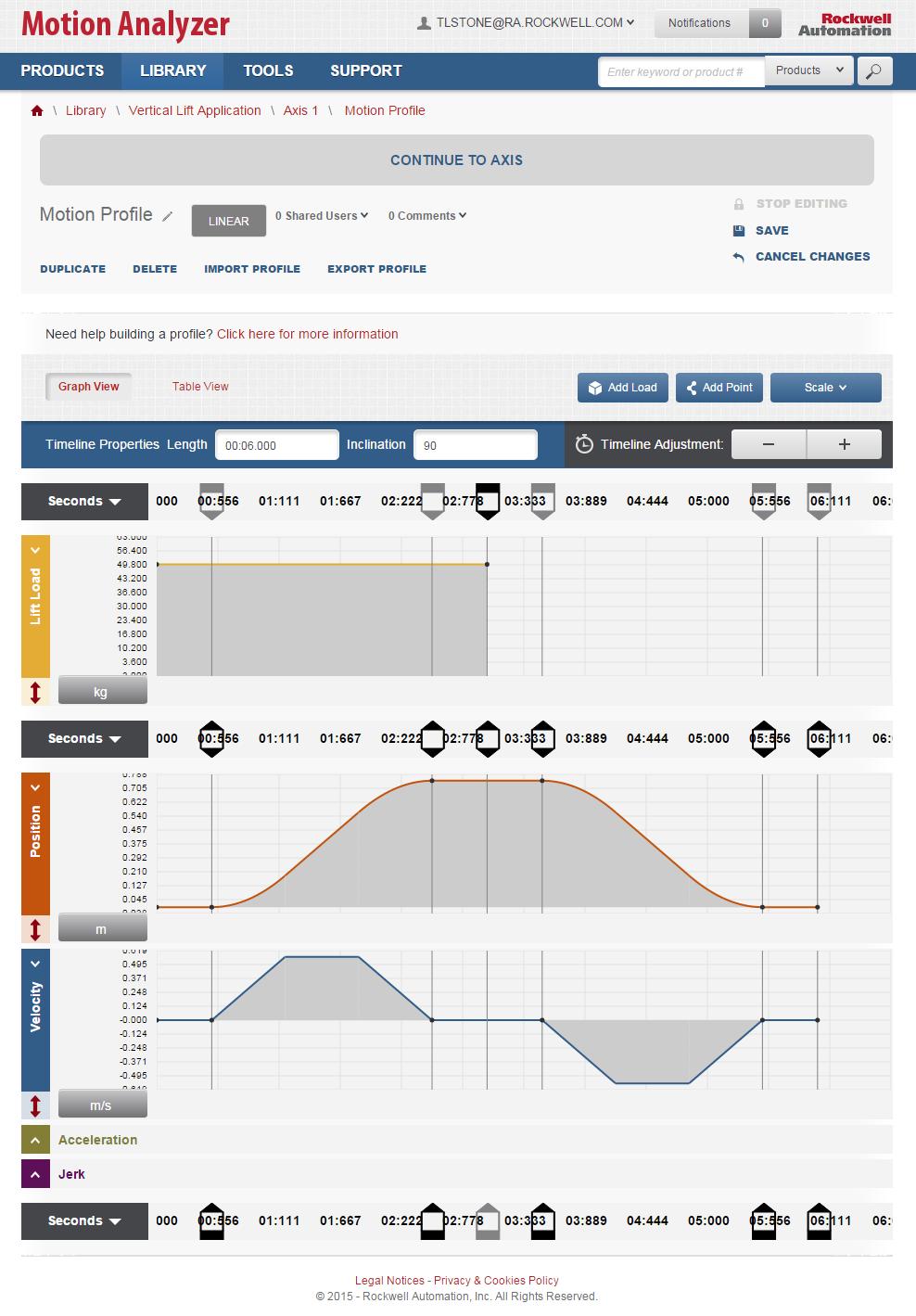
57 Defining a Motion Profile Here is the motion profile that has been specified for the application. Let s look at how to enter this information into the Profile page in Motion Analyzer. 1. The motion profile for this application is in terms of position. To enter a position profile data point, click anywhere on the Position Plot. The Add Point dialog box will appear. 55 of 114


58 2. Change the distance units to meters by clicking on the Distance units button and selecting m. 3. With the Absolute entry method selected, replace the pre-selected time value with 0.5 s and the pre-selected velocity value with 0 m/s. The distance value is calculated from the velocity and time values that you enter, so you do not need to enter a value for distance. 56 of 114

59 4. Click the Submit button. This will produce a dwell for 0.5 seconds at the beginning of the profile. 5. Now we will add an Index segment to the plot. Click anywhere on the Position Plot to add a second point. Note: For convenience, the profile is included here. 57 of 114


60 6. In the Add Point dialog box, change the segment type to Index Segment. 7. With the Absolute entry method selected, replace the pre-selected time value with 2.5 s, the pre-selected Distance value with 0.75 m, and the pre-selected velocity value with 0 m/s. Next, set the Accel. and Decel. Jerk values to 0.5 %. 58 of 114

61 8. Click the Submit button. 9. Click the icon on the Position Plot to automatically zoom the Position Plot. 59 of 114


62 10. You can now clearly see that we have created a 0.5 second dwell segment and an index segment which moves the load to the 0.75 meter position at 2.5 seconds. 11. Enter the remaining profile points for the application. Note: If you need to edit any of the points that you have entered on the plot, there are two methods you can use. Click and Drag Method: To adjust the value of a point on a plot, hover your mouse over the point until the icon appears. Click and drag the point to adjust the point value. Similarly, to adjust the time value of a point, hover your mouse over the time line until the icon appears. Click and drag the line to adjust the time value. Single Click Point Method: To adjust the value of a point on the velocity plot, hover your mouse over the point until the icon appears and click the point. The edit window will re-open. You can use this method to fine tune after using click and drag. Table Edit Method: Alternatively, Click on the Table View button and the Table entry page will appear. Click on the Edit button of the point you would like to edit. 60 of 114
63 Enter the new values in the Edit Point dialog box. 61 of 114

64 12. Since this is a vertical application, enter 90 degrees for the inclination. 62 of 114

65 13. Click anywhere on the Lift Load Plot to add a point. The Add dialog opens. 14. Add the 50 kilogram load point at 3 seconds on the Load Plot. Click the Submit button. 15. Click on the icon under the Lift Load Plot. This will automatically zoom the plot. 63 of 114
66 16. When you have finished entering all of the Motion profile information, your load, position and velocity plots should look like this: 64 of 114
67 65 of 114


68 17. Click the Save button to save the Motion Profile for the application. Then click the Continue to Axis button to return to the Axis page. Once you are at the axis, you can see that it automatically saves. 66 of 114

69 Entering a Mechanism Now that the load and profile information has been entered, let s begin entering the data for the mechanism. The mechanism translates the rotational motion from the motor into linear motion of the lift table. 1. Click on the Define Custom button for the Linear Mechanism. 67 of 114


70 2. Select Belt Drive in the Pick A Type drop-down list, and click the OK button. 3. Enter a Name for the Belt Drive in the next dialog box, and click the OK button. 68 of 114
71 4. Enter 125 millimeters as the diameter of the Driver and Idler (Group 1) in the Parameters table. 69 of 114
72 5. Next we will calculate the inertia of the driver which consists of two sprockets and one shaft. Click on the Inertia Calculator button for the Driver. 70 of 114

73 6. The Inertia Calculator tool will appear. Select Solid Cylinder as the Type, Steel as the Material and enter a Name. 71 of 114

74 7. The length of each sprocket is 25 millimeters and the diameter is 125 millimeters. Enter this information into the calculator, and then click the Save button to add the inertia of the first sprocket to the Load Elements list. 72 of 114
75 8. Repeat steps 6 and 7 for the second sprocket and the shaft. Note: For convenience, the mechanical requirements for the belt mechanism are repeated here: 9. Once you have saved all three inertia values, click the Apply button to enter the total inertia of the Driver into the properties table. 73 of 114
76 10. For this application, there is a Single Idler group that has identical parameters to the Driver group, so we can reuse the inertia value that we calculated. Copy the inertia value of the Driver and paste it into the Inertia field for Idler Group 1. Note: When copying, make sure to select the entire number (the entire number is not visable in the box) by double clicking on the number. 74 of 114
77 11. Enter 1 as the Number of Rollers for Idler Group 1 and enter the Table Mass and the Belt Mass under Additional Loads. Note: For convenience, the mechanical requirements for the belt mechanism are repeated here: 75 of 114

78 12. Once you have entered all of the data for the Belt Mechanism, click the Save button and then the Continue to Axis button. 76 of 114
79 Entering Transmission Components Now we will enter the transmission data for the application. 1. Click on the Define Custom button for the Transmission. 77 of 114

80 2. The first transmission we will create is the coupling. Enter a name for the transmission component, and click the OK button. 3. Select Coupling as the Transmission Type. 78 of 114

81 4. Enter 1 for the coupling transmission ratio. 5. Enter the remaining data that was provided for the coupling. Note: For convenience, the mechanical requirements for the coupling are repeated here: 79 of 114
82 6. Once the coupling data has been entered, click on the Save button and then the Continue to Axis button. 80 of 114
83 7. Now we will add the second transmission component. Click on the Add Another button under the Transmission heading. 81 of 114

84 8. Click on the Define Custom button under the new transmission heading you just added. 9. The second transmission we will create is the belt. Enter a name for the transmission component, and click the OK button. 82 of 114

85 10. Select Belt Drive as the transmission type. 11. Enter the data that was provided for the belt. Note: For convenience, the mechanical requirements for the belt transmission are repeated here: 83 of 114

86 12. Once the belt data has been entered, click on the Save button and then click the Continue to Axis button. 84 of 114
87 13. Although a gearbox is not needed for this application, let s take a look at the steps you would follow to add one. Begin by clicking the Add Another button. 85 of 114


88 14. Click on the Add Partner Gearbox button for the Transmission that you just added. 15. In the By Browsing tab, select Browse Products. 86 of 114

89 16. You will now see a variety of gearboxes separated by their company. 87 of 114
90 17. Click on the Go to Axis button to return to the axis page without selecting a gearbox. 88 of 114

91 Selecting a Motor and Drive Now that you have entered all of the mechanical and motion profile data into Motion Analyzer, you are ready to select a Drive and Motor for the application. 1. Begin by selecting 460 for the Voltage and 3 for the Phase in the Power Requirements section of the Axis page. Your axis is now automatically saved. 89 of 114
92 2. Next, click on the Search for solutions button. 90 of 114


93 3. After Motion Analyzer performs the necessary calculations, the Solution List will appear with a list of the motor and drive combinations which meet the application requirements. 4. Click the Expand button next to Product Family Matrix. 91 of 114
94 5. Here you can view a table of all the drives and motors that fit the solution. 92 of 114
95 6. Let s narrow the search results by selecting the Kinetix 5700 Servo Drive Family. Click on the KINETIX 5700 SERVO DRIVE heading in the Product Family table. 93 of 114

96 7. Collapse the Product List by clicking on the carrot for the list. 94 of 114

97 8. Next, sort the solution list by Bus Utilization in the Sort by dropdown menu. 95 of 114
, by clicking the Select button next to that combination.")
98 9. Select the third solution on the list, the Kinetix 5500 drive (2198-H015) and the MPL motor (MPL-B540D), by clicking the Select button next to that combination. 96 of 114

99 10. Your Axis will then automatically save. 97 of 114

100 11. Next, we will select the configuration for the motor and drive. Click on the Select Configuration for the MPL motor. 98 of 114
101 12. On the MP-Series Motor Configuration Selection page, select the option with no DC brake and the Multi-turn absolute feedback type. 99 of 114

102 13. Click the Save Axis button to set the configuration. 14. Click the OK button in the dialog box that appears to return to the Axis page. 100 of 114

103 15. Next, we will select the configuration for the Kinetix 5500 drive. Scroll to the right in the Components section of the page to see the options for the selected Drive. Then, click the Select Configuration button for the Kinetix 5500 drive. 101 of 114

104 16. Select the Integrated Safe Torque Off version of the Kinetix 5500 drive. 102 of 114

105 17. Click the Save Axis button to set the configuration. 18. Click the OK button in the dialog box that appears to return to the Axis page. 103 of 114

106 19. Click on the Performance tab to see the performance curves for the solution you have selected. 104 of 114
107 20. The Performance page for the axis allows you to analyze the Torque/Speed, Power/Speed, and Thermal Performance plots for the solution you have selected. 105 of 114

108 21. Click on the Continue to Project button to return to the Vertical Lift Application Project Detail page. 106 of 114

109 22. Click on the Power Analysis tab for the application. 107 of 114
110 23. The Power Analysis page includes information on power and bus utilization. For this application, the Shunt Utilization is well within the acceptable range, so there is no need to add aditional shunts or capacitor modules. 108 of 114
111 109 of 114
112 This completes the Motion Analyzer Lab. 110 of 114
113 Notes: 111 of 114
114 Publication XXXX-XX###X-EN-P Month Year Supersedes Publication XXXX-XX###X-EN-P Month Year Copyright 2012 Rockwell Automation, Inc. All rights reserved. 112 of 114
Product Compatibility and Download Center
 Product Compatibility and Download Center Important User Information This documentation, whether, illustrative, printed, online or electronic (hereinafter Documentation ) is intended for use only as a
Product Compatibility and Download Center
 Product Compatibility and Download Center Important User Information This documentation, whether, illustrative, printed, online or electronic (hereinafter Documentation ) is intended for use only as a
Bus Regulation. PowerFlex 755 AC Drives. For Classroom Use Only!
 Bus Regulation PowerFlex 755 AC Drives For Classroom Use Only! Important User Information This documentation, whether, illustrative, printed, online or electronic (hereinafter Documentation ) is intended
For Classroom Use Only! Flying Start PowerFlex 755 AC Drives
 For Classroom Use Only! Flying Start PowerFlex 755 AC Drives Important User Information This documentation, whether, illustrative, printed, online or electronic (hereinafter Documentation ) is intended
L12 - Studio 5000 and Logix: Basics Lab. For Classroom Use Only!
 L12 - Studio 5000 and Logix: Basics Lab For Classroom Use Only! Important User Information This documentation, whether, illustrative, printed, online or electronic (hereinafter Documentation ) is intended
L01 - Effective Design Methods for Integrating Safety Using Logix Controllers. For Classroom Use Only!
 L01 - Effective Design Methods for Integrating Safety Using Logix Controllers For Classroom Use Only! Important User Information This documentation, whether, illustrative, printed, online or electronic
Kinetix 6000 Axis Module and Shunt Module
 Installation Instructions Kinetix 6000 and Shunt Module Catalog Numbers 2094-AMxx, 2094-BMxx 2094-AMxx-S, 2094-BMxx-S 2094-BSP2 Topic Page About This Publication 1 Important User Information 2 Before You
PowerMonitor 5000 Unit Catalog Number Upgrade
 Installation Instructions PowerMonitor 5000 Unit Catalog Number Upgrade Catalog Numbers 1426-MxE-xxx Topic Page Upgrade the Device Catalog Number with the ControlFLASH Utility 3 Determine Communication
Sizing PlantPAx System Architecture for Optimal Performance. For Classroom Use Only!
 Sizing PlantPAx System Architecture for Optimal Performance For Classroom Use Only! Important User Information This documentation, whether, illustrative, printed, online or electronic (hereinafter Documentation
GuardLogix Controller to Kinetix 6000 Drive with Safe-Off using EtherNet/IP CompactBlock Guard I/O Module
 Safety Application Example GuardLogix Controller to Kinetix 6000 Drive with Safe-Off using EtherNet/IP CompactBlock Guard I/O Module Safety Rating: SIL3/Category 3 (also see SIL3/CAT4 section), according
L15 - Tools that Simplify Product Sizing, Selection and Design. For Classroom Use Only!
 L15 - Tools that Simplify Product Sizing, Selection and Design For Classroom Use Only! Important User Information This documentation, whether, illustrative, printed, online or electronic (hereinafter Documentation
Motion Analyzer 4.73 Release Notes
 Motion Analyzer 4.73 Release Notes Issues Resolved Motion Analyzer 4.73 1. Motion Analyzer Versions 4.6 through 4.72 will interfere with the installation of RSLogix 5000 software. This has been corrected
PowerMonitor 1000 Unit Catalog Number Upgrade
 Installation Instructions PowerMonitor 1000 Unit Catalog Number Upgrade Catalog Numbers 1408-UPT1-E3, 1408-UPT2-E3, 1408-UPE1-E3, 1408-UPE2-E3, 1408-UP485-ENT, 1408-UPT3-E3 Topic Important User Information
Studio 5000 Architect Getting Results Guide
 Getting Results Studio 5000 Architect Getting Results Guide Rockwell Automation Publication ARCH-GR001I-EN-E Supersedes Publication ARCH-GR001H-EN-E Important user information Read this document and the
InView Firmware Update
 Installation Instructions InView Firmware Update Topic Page Hazardous Voltage 3 Change EPROM on 2706-P72, 2706-P74 Display 3 Change EPROM on 2706-P42, 2706-P44 Displays 5 Firmware Upgrade Kit 7 2 InView
Differential Liquid/Gas Pressure Transmitter
 Installation Instruction Differential Liquid/Gas Pressure Transmitter Catalog Number(s) 1414-CPZ10FWFAA, 1414-IPZ10FWFAA Explosion Hazard WARNING Do not use in an explosive or hazardous environment, with
Using GuardShield Light Curtains (Safe 4, Micro 400, or 440L), with ArmorBlock Guard I/O and SmartGuard Controller
, with ArmorBlock Guard I/O and SmartGuard Controller") Safety Application Example Using GuardShield Light Curtains (Safe 4, Micro 400, or 440L), with ArmorBlock Guard I/O and SmartGuard Controller Light Curtain with On-machine Components Safety Rating: Category
Safety Application Example Using GuardShield Light Curtains (Safe 4, Micro 400, or 440L), with ArmorBlock Guard I/O and SmartGuard Controller Light Curtain with On-machine Components Safety Rating: Category
Micro800 Programmable Controllers: Getting Started with Motion Control Using a Simulated Axis
 Quick Start Micro800 Programmable Controllers: Getting Started with Motion Control Using a Simulated Axis Catalog Numbers Bulletin 2080-LC30, 2080-LC50 Important User Information Solid-state equipment
GV3000/SE General Purpose (Volts/Hertz) and Vector Duty AC Drive, HP, 230V AC
 and Vector Duty AC Drive, HP, 230V AC") Software Start-Up and Reference Manual D2-3416-2 GV3000/SE General Purpose (Volts/Hertz) and Vector Duty AC Drive, 30-100 HP, 230V AC Version 6.04 Important User Information Solid-state equipment has operational
Software Start-Up and Reference Manual D2-3416-2 GV3000/SE General Purpose (Volts/Hertz) and Vector Duty AC Drive, 30-100 HP, 230V AC Version 6.04 Important User Information Solid-state equipment has operational
PCI Expansion Slot Kit for 6181P (1500P) Series D Integrated Display Computer
 Series D Integrated Display Computer") Installation Instructions PCI Expansion Slot Kit for 6181P (1500P) Series D Integrated Display Computer Catalog Number 6189V-2PCI15R Topic Page About This Publication 1 Important User Information 2 Safety
Installation Instructions PCI Expansion Slot Kit for 6181P (1500P) Series D Integrated Display Computer Catalog Number 6189V-2PCI15R Topic Page About This Publication 1 Important User Information 2 Safety
Using TLS3-GD2 Guardlocking Interlock with ArmorBlock Guard I/O and SmartGuard Controller
 Safety Application Example Using TLS3-GD2 Guardlocking Interlock with ArmorBlock Guard I/O and SmartGuard Controller Guardlocking with On-machine Components Safety Rating: Category 3, according to EN954-1
Kinetix 300 Memory Module Programmer
 Kinetix 300 Memory Module Programmer Catalog Number 2097-PGMR Topic About the Memory Module Programmer 1 Parts List 3 Batteries Operation 4 Using Memory Module Programmer 6 Switch On/Off Memory Module
Simple Motion Control Connected Components Building Block. Quick Start
 Simple Motion Control Connected Components Building Block Quick Start Important User Information Solid state equipment has operational characteristics differing from those of electromechanical equipment.
GuardLogix: Dual Zone Gate Protection with E-stop and Trojan Interlock Switch
 Safety Application Example GuardLogix: Dual Zone Gate Protection with E-stop and Trojan Interlock Switch Safety Rating: PLd, Cat. 3 to EN ISO 13849.1 2008 Introduction... 2 Important User Information...
GuardLogix: Safety Gate Application with SensaGuard Switch
 Safety Application Example GuardLogix: Safety Gate Application with SensaGuard Switch Safety Rating: PLe, Cat. 4 to EN ISO 13849.1 2008 Introduction...2 Important User Information...2 General Safety Information...3
Throughout this manual we use notes to make you aware of safety considerations:
 Because of the variety of uses for the products described in this publication, those responsible for the application and use of this control equipment must satisfy themselves that all necessary steps have
Import/Export Project Components. Programming Manual
 Import/Export Project Components Programming Manual Important User Information Solid state equipment has operational characteristics differing from those of electromechanical equipment. Safety Guidelines
Motion Analyzer Release Notes
 Motion Analyzer 5.100 Release Notes Product Data Updates for Motion Analyzer 5.100 Incorporation of Medusa Cables Shimpo Gearboxes added Alpha TPA+ gearboxes added Alpha CP gearboxes restored HPK-B2510C
Introduction to Micro800 Motion. For Classroom Use Only!
 Introduction to Micro800 Motion For Classroom Use Only! Important User Information This documentation, whether, illustrative, printed, online or electronic (hereinafter Documentation ) is intended for
GuardLogix: TLS Guardlocking Application
 Safety Application Example GuardLogix: TLS Guardlocking Application Safety Rating: PLd, Cat. 3 to EN ISO 13849.1 2008 Introduction... 2 Important User Information... 2 General Safety Information... 3 Description...
Adapter Kit for PanelView 1200/1200e Touch Screen Terminal Cutout
 Installation Instructions Adapter Kit for PanelView 1200/1200e Touch Screen Terminal Cutout Catalog Numbers 2711-NR5T, 2711P-RAT12E2 Topic Page About This Publication 1 Important User Information 2 About
Application Guide. Considerations for 32 Bit Integer Parameters in 16 Bit Processors. PowerFlex 700VC, PowerFlex 700S. Introduction.
 Topic: Drive Product: Introduction User Information Considerations for 32 Bit Integer Parameters in 16 Bit Processors PowerFlex 700VC, PowerFlex 700S An Application Guide provides generic information on
ProcessLogix R510.0 Server Installation Instructions
 ProcessLogix R510.0 Server Installation Instructions Installation Instructions Before you begin... This publication guides you through the remaining processes required to initialize a ProcessLogix Server.
Using the New Profile Editor
 Using the New Profile Editor Introduction Welcome to the new motion profile editor for Motion Analyzer Online! We ve gathered a lot of feedback from our users and have incorporated it into the latest release.
Color-Sensing Connected Components Building Block. Quick Start
 Color-Sensing Connected Components Building Block Quick Start Important User Information Solid state equipment has operational characteristics differing from those of electromechanical equipment. Safety
DriveGuard. Safe-Off Option for PowerFlex 70 AC Drives. User Manual.
 DriveGuard Safe-Off Option for PowerFlex 70 AC Drives User Manual www.abpowerflex.com Important User Information Solid state equipment has operational characteristics differing from those of electromechanical
CompactLogix Power Supplies Specifications
 Technical Data CompactLogix Power Supplies Specifications 1768 CompactLogix Power Supplies Catalog Numbers 1768-PA3, 1768-PB3 1769 Compact I/O Power Supplies Catalog Numbers 1769-PA2, 1769-PB2, 1769-PA4,
SequenceManager Controls
 Reference Manual SequenceManager Controls 1756 ControlLogix, 1756 GuardLogix, 1769 CompactLogix, 1769 Compact GuardLogix, 1789 SoftLogix, Studio 5000 Logix Emulate Important user information Read this
The Guardmaster 440C-CR30 Software Configurable Safety Relay Training Demo Lab. For Classroom Use Only!
 The Guardmaster 440C-CR30 Software Configurable Safety Relay Training Demo Lab For Classroom Use Only! Important User Information This documentation, whether, illustrative, printed, online or electronic
Solar Combiner Enclosure
 Installation Instructions Solar Combiner Enclosure Catalog Numbers 1000-SB006, 1000-SB012 Topic Page Description 1 Important Safety Instructions 3 Nameplate Data 4 Planning for Installation 4 Install the
Teaching Color-Sensing Connected Components Building Block. Quick Start
 Teaching Color-Sensing Connected Components Building Block Quick Start Important User Information Solid state equipment has operational characteristics differing from those of electromechanical equipment.
Simple Package Measurement Connected Components Building Block. Quick Start
 Simple Package Measurement Connected Components Building Block Quick Start Important User Information Solid state equipment has operational characteristics differing from those of electromechanical equipment.
InView Communication Modules
 Installation Instructions InView Communication Modules Catalog Numbers 2706-PxM, 2706-PxK, 2706-PxP Topic Page About This Publication 1 Important User Information 2 Power Supply Requirements 3 Mount the
Digital ac/dc (24V) Input Module
 Input Module") Installation Instructions Digital ac/dc (24V) Input Module Catalog Number 1771-IND, Series C Topic Page Important User Information 2 Before You Begin 3 Power Requirements 3 Prevent Electrostatic Discharge
Installation Instructions Digital ac/dc (24V) Input Module Catalog Number 1771-IND, Series C Topic Page Important User Information 2 Before You Begin 3 Power Requirements 3 Prevent Electrostatic Discharge
StruxureWare. Power Monitoring Expert 8.2 Hierarchy Manager Help Topics 7EN /2017
 StruxureWare Power Monitoring Expert 8.2 Hierarchy Manager Help Topics 7EN52-0413-00 03/2017 Legal Information The Schneider Electric brand and any registered trademarks of Schneider Electric Industries
PowerFlex 70 Safe-Off Control EtherNet/IP Guard I/O Safety Module and GuardLogix Integrated Safety Controller
 Safety Application Example PowerFlex 70 Safe-Off Control EtherNet/IP Guard I/O Safety Module and GuardLogix Integrated Safety Controller Safety Rating: Category 3 (also see Achieving a Cat. 4 Safety Rating)
Visual Physics Introductory Lab [Lab 0]
![Visual Physics Introductory Lab [Lab 0]](/thumbs/74/69956143.jpg "Visual Physics Introductory Lab [Lab 0]") Your Introductory Lab will guide you through the steps necessary to utilize state-of-the-art technology to acquire and graph data of mechanics experiments. Throughout Visual Physics, you will be using
Your Introductory Lab will guide you through the steps necessary to utilize state-of-the-art technology to acquire and graph data of mechanics experiments. Throughout Visual Physics, you will be using
Micro800 Programming Basics. For Classroom Use Only!
 Micro800 Programming Basics For Classroom Use Only! Important User Information This documentation, whether, illustrative, printed, online or electronic (hereinafter Documentation ) is intended for use
Turn Control System Data into Improved Business Performance leveraging FactoryTalk Products. For Classroom Use Only! Allen-Bradley
 Turn Control System Data into Improved Business Performance leveraging FactoryTalk Products For Classroom Use Only! Allen-Bradley Important User Information This documentation, whether, illustrative, printed,
Installation Instructions
 Installation Instructions (Cat. No. 1771-OBN Series B) Use this document as a guide when installing the catalog number 1771-OBN series B output module. Because of the variety of uses for the products described
ControlLogix Redundancy Update and Module Replacement Guidelines
 Reference Manual Original Instructions ControlLogix Redundancy Update and Module Replacement Guidelines Product Family ControlLogix 5570 Controllers Important User Information Read this document and the
ASTRA USER GUIDE. 1. Introducing Astra Schedule. 2. Understanding the Data in Astra Schedule. Notes:
 ASTRA USER GUIDE 1. Introducing Astra Schedule Astra Schedule is the application used by Academic Space Scheduling & Utilization to schedule rooms for classes and by academic colleges, schools, and departments
Advanced PLC Topics for Micro800 Controllers with Motion Capabilities and CIP Messaging Functionality. For Classroom Use Only!
 Advanced PLC Topics for Micro800 Controllers with Motion Capabilities and CIP Messaging Functionality For Classroom Use Only! Important User Information This documentation, whether, illustrative, printed,
Installation Instructions
 Installation Instructions (Catalog Number 1771-OD) This document provides information on: Because of the variety of uses for the products described in this publication, those responsible for the application
Application Technique. Safety Function: Safety Camera with E-stop
 Application Technique Safety Function: Safety Camera with E-stop Products: Guardmaster Dual-input Safety Relay, Guardmaster SC300 Safety Camera Safety Rating: PLd, Cat. 3 to EN ISO 13849-1: 2008 2 Safety
[ Getting Started with Analyzer, Interactive Reports, and Dashboards ] ]
![[ Getting Started with Analyzer, Interactive Reports, and Dashboards ] ]](/thumbs/88/117545107.jpg "[ Getting Started with Analyzer, Interactive Reports, and Dashboards ] ]") Version 5.3 [ Getting Started with Analyzer, Interactive Reports, and Dashboards ] ] https://help.pentaho.com/draft_content/version_5.3 1/30 Copyright Page This document supports Pentaho Business Analytics
Version 5.3 [ Getting Started with Analyzer, Interactive Reports, and Dashboards ] ] https://help.pentaho.com/draft_content/version_5.3 1/30 Copyright Page This document supports Pentaho Business Analytics
Visual Physics - Introductory Lab Lab 0
 Your Introductory Lab will guide you through the steps necessary to utilize state-of-the-art technology to acquire and graph data of mechanics experiments. Throughout Visual Physics, you will be using
FactoryTalk View Site Edition - Building Applications Lab. For Classroom Use Only!
 FactoryTalk View Site Edition - Building Applications Lab For Classroom Use Only! Important User Information This documentation, whether, illustrative, printed, online or electronic (hereinafter Documentation
Logix5000 Controllers Function Block Diagram
 Logix5000 Controllers Function Block Diagram Catalog Numbers 1756 ControlLogix, 1769 CompactLogix, 1789 SoftLogix, 1794 FlexLogix, PowerFlex 700S with DriveLogix Programming Manual Important User Information
Aboriginal Information Systems. Per Capita Distribution TOBTAX. User Reference
 Aboriginal Information Systems Per Capita Distribution TOBTAX User Reference Custom Software. Network Services. E-Business. Complete I T Solutions. 2005 - Advanced DataSystems Ltd. Copyright Information
Version 1.2. January Publication ERSC-1300
 Version 1.2 January 2016 Publication ERSC-1300 ConveyLinx module firmware and functionality is protected by U.S. and international patents. For complete patent information visit www.pulseroller.com/patents
Installation Instructions
 Installation Instructions Cat. No. 1771 P3, P4, P5 and P5E Use this document as a guide when installing the catalog number 1771-P3, -P4, -P5 or -P5E power supplies. Because of the variety of uses for the
Schneider Electric License Manager
 Schneider Electric License Manager EIO0000001070 11/2012 Schneider Electric License Manager User Manual 12/2012 EIO0000001070.01 www.schneider-electric.com The information provided in this documentation
Allen-Bradley Motors
 Installation Instructions Firmware Update Instructions for Ethernet, Enhanced and ControlNet PLC-5 Programmable Controllers Purpose Firmware Update Kit Contents Hardware and Software Requirements This
Catalog Numbers 9308-RSFB64ENE, 9308-RSFB256ENE, 9308-RSFB1024ENE
 Release Notes RSFieldbus Software Catalog Numbers 9308-RSFB64ENE, 9308-RSFB256ENE, 9308-RSFB1024ENE Topic Page Important User Information 2 Before You Begin 3 Software Requirements 4 Install the Software
User Guide. Avery Dennison Web Ordering Solution for Steinmart
 User Guide Avery Dennison Web Ordering Solution for Steinmart March 2012 Copyright 2012 A very Dennison The information in this document is subject to change without notice and should not be construed
Quick Start. Logix5000 Control Systems: Connect Kinetix 350 Drives over an EtherNet/IP Network
 Quick Start Logix5000 Control Systems: Connect Kinetix 350 Drives over an EtherNet/IP Network Important User Information Read this document and the documents listed in the additional resources section
Logix5000 Controllers Nonvolatile Memory Card
 Programming Manual Logix5000 Controllers Nonvolatile Memory Card 1756 ControlLogix, 1756 GuardLogix, 1769 CompactLogix, 1769 Compact GuardLogix, 1789 SoftLogix, 5069 CompactLogix, Studio 5000 Logix Emulate
Schneider Electric Floating License Manager
 Schneider Electric Floating License Manager EIO0000001078 11/2012 Schneider Electric Floating License Manager User Manual 12/2012 EIO0000001078.01 www.schneider-electric.com The information provided in
Micro800 Programming Basics. For Classroom Use Only!
 Micro800 Programming Basics For Classroom Use Only! Important User Information This documentation, whether, illustrative, printed, online or electronic (hereinafter Documentation ) is intended for use
GV3000/SE Operator Interface Module (OIM) User Guide Version 2.0 M/N 2RK3000
 User Guide Version 2.0 M/N 2RK3000") GV3000/SE Operator Interface Module (OIM) User Guide Version 2.0 M/N 2RK3000 Instruction Manual D2-3342-2 The information in this manual is subject to change without notice. Throughout this manual, the
GV3000/SE Operator Interface Module (OIM) User Guide Version 2.0 M/N 2RK3000 Instruction Manual D2-3342-2 The information in this manual is subject to change without notice. Throughout this manual, the
Distributed Power System SA3100 Drive Configuration and Programming
 Distributed Power System SA3100 Drive Configuration and Programming Instruction Manual S-3056-1 Throughout this manual, the following notes are used to alert you to safety considerations:! ATTENTION: Identifies
ControlLogix SIL2 System Configuration
 ControlLogix SIL2 System Configuration Using RSLogix 5000 Subroutines Application Technique (Catalog Numbers 1756 and 1492) Important User Information 8 / 2011 Solid state equipment has operational characteristics
FlexPak 3000 Drive Operator Interface Module (OIM) User s Guide
 User s Guide") FlexPak 3000 Drive Operator Interface Module (OIM) User s Guide Instruction Manual D2-3344 The information in this manual is subject to change without notice. Throughout this manual, the following notes
FlexPak 3000 Drive Operator Interface Module (OIM) User s Guide Instruction Manual D2-3344 The information in this manual is subject to change without notice. Throughout this manual, the following notes
Trusted Toolset Application Validator Software Package
 PD-T8015 Trusted Trusted Toolset Application Validator Software Package Product Overview The IEC 61131 TOOLSET Application Validators are a suit of four programs that enable the applications developer
WebPakCS Software Version 1.0
 WebPakCS Software Version 1.0 Instruction Manual D2-3447 The information in this manual is subject to change without notice. Throughout this manual, the following notes are used to alert you to safety
Avigilon Gateway Web Client User Guide. Version 6.10
 Avigilon Gateway Web Client User Guide Version 6.10 2006-2018, Avigilon Corporation. All rights reserved. AVIGILON, the AVIGILON logo, AVIGILON CONTROL CENTER, ACC, and TRUSTED SECURITY SOLUTIONS. are
NHP SAFETY REFERENCE GUIDE
 NHP SAFETY REFERENCE GUIDE GuardLogix SAFETY FUNCTION DOCUMENTS Cable Pull Switch - Products: GuardLogix Series Connection of Cable Pull Switches Safety Rating: PLd, Cat. 3 to EN ISO 13849-1: 2008 Table
Micro800 Controllers Starter Pack Quick Start
 Quick Start Micro800 Controllers Starter Pack Quick Start Catalog Numbers Bulletin 2080-LC20, 2080-LC30, 2080-LC50 Important User Information Read this document and the documents listed in the additional
EcoStruxure Power Commission Installation Guide
 EcoStruxure Power Commission DOCA0134EN 03/2019 EcoStruxure Power Commission Installation Guide 03/2019 DOCA0134EN-04 www.schneider-electric.com The information provided in this documentation contains
0Acknowledgement. This application has been developed with the cooperation of the Inter-agency Group for Child Mortality Estimation.
 r4 0Acknowledgement This application has been developed with the cooperation of the Inter-agency Group for Child Mortality Estimation. 1Contents Introduction... 6 User Levels... 6 Learning CME Info...
Software User Documentation
 ` Software User Documentation For Microcare MPPT Data Acquisition Application Page i Prepared by: Microcare www.microcare.co.za Revision Sheet Release No. Date Revision Description 1 21/10/14 Original
L14 - Speed Integration with Ethernet-enabled CENTERLINE MCCs, Rockwell Software Studio 5000 and IntelliCENTER Software
 L14 - Speed Integration with Ethernet-enabled CENTERLINE MCCs, Rockwell Software Studio 5000 and IntelliCENTER Software For Classroom Use Only! Important User Information This documentation, whether, illustrative,
Practical Training with the maxon Selection Program (MSP)
") Practical Training with the maxon Selection Program (MSP) Purposes and Goals The participants - learn how to use the main parts of the maxon selection program. - make a motor-gearhead selection for continuous
Practical Training with the maxon Selection Program (MSP) Purposes and Goals The participants - learn how to use the main parts of the maxon selection program. - make a motor-gearhead selection for continuous
Using a Guard Locking Interlock Switch and Light Curtains with DeviceNet Guard I/O and a GuardLogix Controller
 Safety Application Example Using a Guard Locking Interlock Switch and Light Curtains with DeviceNet Guard I/O and a GuardLogix Controller Safety Rating: Category 3, according to EN954-1 Introduction...
Extending FactoryTalk View Site Edition with ACP ThinManager and Relevance. Doug Coulter
 Extending FactoryTalk View Site Edition with ACP ThinManager and Relevance Doug Coulter dcoulter@thinmanager.com Important User Information This documentation, whether, illustrative, printed, online or
Important User Information
 Important User Information Because of the variety of uses for the products described in this publication, those responsible for the application and use of this control equipment must satisfy themselves
Rockwell Automation Library of Steam Table Instructions
 Reference Manual Original Instructions Rockwell Automation Library of Steam Table Instructions Version 4.0 Important User Information Read this document and the documents listed in the additional resources
Astra Scheduling Grids
 Astra Scheduling Grids To access the grids, click on the Scheduling Grids option from the Calendars tab. A default grid will be displayed as defined by the calendar permission within your role. Choosing
DeviceNet Communications
 DeviceNet Communications For PanelView Plus and PanelPlus CE Terminals 2711P User Manual Important User Information Solid state equipment has operational characteristics differing from those of electromechanical
GV3000/SE 230 VAC 1-20 HP General Purpose (Volts/Hertz) and Vector Duty Drive Software Start-Up and Reference Manual Version 6.04
 and Vector Duty Drive Software Start-Up and Reference Manual Version 6.04") GV3000/SE 230 VAC 1-20 HP General Purpose (Volts/Hertz) and Vector Duty Drive Software Start-Up and Reference Manual Version 6.04 Instruction Manual D2-3387-4 The information in this manual is subject
GV3000/SE 230 VAC 1-20 HP General Purpose (Volts/Hertz) and Vector Duty Drive Software Start-Up and Reference Manual Version 6.04 Instruction Manual D2-3387-4 The information in this manual is subject
Date 18/05/17. Operation and maintenance instructions for driver configurator QSet
 Operation and maintenance instructions 28 1. General recommendations The recommendations regarding safe use in this document should be observed at all times. Some hazards can only be associated with the
Kinetix 5700 Safe Monitor Functions
 Safety Reference Manual Original Instructions Kinetix 5700 Safe Monitor Functions Catalog Numbers 2198-D006-ERS3, 2198-D012-ERS3, 2198-D020-ERS3, 2198-D032-ERS3, 2198-D057-ERS3 2198-S086-ERS3, 2198-S130-ERS3,
DeviceNet Network Configuration
 User Manual DeviceNet Network Configuration 1756 ControlLogix, 1756 GuardLogix, 1769 CompactLogix, 1769 Compact GuardLogix, 1789 SoftLogix, Studio 5000 Logix Emulate Important User Information Solid-state
Migration Guide. Ultra3000 Digital Servo Drives to Kinetix 5500 Servo Drives
 Migration Guide Ultra3000 Digital Servo Drives to Kinetix 5500 Servo Drives Important User Information Read this document and the documents listed in the additional resources section about installation,
Studio 5000 View Designer Getting Started Guide
 Publication 9324-QS001A-EN-D - September 2015 This publication is not superseded by another version Important user information Read this document and the documents listed in the additional resources section
RealPresence Media Manager
 RealPresence CloudAXIS Suite Administrators Guide Software 1.3.1 USER GUIDE Software 6.7 January 2015 3725-75302-001A RealPresence Media Manager Polycom, Inc. 1 Copyright 2015, Polycom, Inc. All rights
Position Control via HMI Connected Components Building Block. Quick Start
 Position Control via HMI Connected Components Building Block Quick Start Important User Information Solid state equipment has operational characteristics differing from those of electromechanical equipment.
General Information 1. Connection 2. User Interface 3 ATC5300. Menus 4. Automatic Transfer Controller. Remote Control Software Manual A5E
 s General Information 1 Connection 2 Automatic Transfer Controller User Interface 3 Menus 4 Remote Control Software Manual Edition 01/2010 A5E02469028-01 Legal information Warning notice system This manual
SharePoint General Instructions
 SharePoint General Instructions Table of Content What is GC Drive?... 2 Access GC Drive... 2 Navigate GC Drive... 2 View and Edit My Profile... 3 OneDrive for Business... 3 What is OneDrive for Business...