DALI Wizard Analysis and commissioning tool for DALI installations ECG configuration tool Light is OSRAM
|
|
|
- Eustacia Jordan
- 5 years ago
- Views:
Transcription
1 DALI Wizard Analysis and commissioning tool for DALI installations ECG configuration tool Light is OSRAM
2 Contents DALI Wizard... 1 Analysis and commissioning tool for DALI installations... 1 ECG configuration tool... 1 Introduction... 3 Field of application... 3 Application note... 3 System requirements... 3 Installation... 3 Description... 4 User interface... 4 Help button... 4 Language button Interface options... 6 Information line... 6 Status line... 6 DALI system topology... 7 Overview... 7 Operation... 7 Wizard panel Light level control panel Light level area Blink sequence area DALI spy panel Button bar Information line Display area Columns Filter Addressing panel Addressing area Identification area Addresses area Control gear state panel Control gear configuration panel Groups area Scene programming Memorybank Panel Panel Corridor Function Panel Touch DIM Configuration Panel Emergency / Power to lamp Panel Monitoring Panel Report Offline Configuration Application examples System documentation Replacing a participant Replacement of control gear with existing configuration file Replacement of a control gear without configuration file Restoration of a system configuration Appendix Symbols for DALI participants and groups Interface symbols Program updates End User Licence Agreement... 32
3 Introduction Field of application Application note System requirements The OSRAM DALI Wizard Software for Microsoft Windows is used for analysing and configuring lighting systems in accordance with DALI Standard IEC and DALI devices. The DALI Magic USB interface from OSRAM is required as the hardware interface between DALI and the PC. Detailed information on DALI Standard IEC can be found at: The OSRAM DALI Wizard software enables the parameters of a preconfigured DALI-controlled lighting system to be modified. Inconsiderate modification of parameters of a DALI-controlled lighting system can lead to extensive malfunctions. In some control devices, modifications in the range of addresses used, in particular, require a complete re-installation by the control device or with the aid of the associated installation software. OSRAM assumes no liability for operative failures of a lighting system where the OSRAM DALI Wizard has been improperly used. The system requirements for the OSRAM DALI Wizard are: OSRAM DALI Magic USB DALI interface PC or Notebook with the following minimum specifications: Pentium M processor 1 GB RAM Windows XP (SP3), Windows Vista or Windows 7 (32-bit and 64-bit) Microsoft.NET Framework 3.5 (SP1) 10 MB hard disk space Monitor with a resolution of 1024x768 pixels One free USB 2.0 port PDF Reader for reading the documentation files Installation After downloading the software from please double-click on the ZIP file. Then start the installation by double-clicking on the Setup file. Follow the instructions of the installation wizard. If Microsoft.NET Framework 3.5 (SP1) is not yet available on your computer, the installation wizard will prompt you to install it. After installation, you can start the OSRAM DALI Wizard by double-clicking on the desktop symbol or using the Windows Start menu "Start" "All Programs" "OSRAM" "DALI Wizard" "OSRAM DALI Wizard". 3

4 Description DALI Wizard Description User interface The user interface of the OSRAM DALI Wizard is divided into 3 main areas. There is also a status line at the lower edge of the window as well as an information line and a button bar in the upper area. Button bar Information line Panel tab area DALI system topology Status line The individual areas are described in the following. All user interface settings of the OSRAM DALI Wizard are saved for the specific user when the program is closed and are reloaded at the start of the OSRAM DALI Wizard. Help button Clicking on Help in the button bar displays a selection menu. If the "Online help" menu item is selected, the manual installed with the software is opened as a PDF document. A PDF Reader must be installed on the PC for this. If the "About" menu item is selected, a dialog appears with the following tabs: 4

5


6 Description DALI Wizard Language button Clicking on Language in the button bar displays a selection menu. Interface options After selecting a language, the OSRAM DALI Wizard has to be restarted to work with the selected language. A corresponding indication will be shown in information line. Clicking on Visibility in the button bar displays a selection menu. Information line In this menu, individual areas of the interface can be enabled and disabled. Activating an area automatically brings it into the foreground. Clicking on Reset layout resets the interface to the original condition when the OSRAM DALI Wizard is next started. Warnings, error messages and general information are output in the information line. For example, file names and paths are also displayed. The messages remain in the information line until they are overwritten by a new message. Error messages will be shown until acknowledged with OK button. Status line Information on the currently connected DALI Magic is displayed in the status line. DALI voltage: As soon as a DALI voltage is applied to the connected DALI Magic, it is signalled by a green display. Internal DALI supply: If the DALI system is supplied from the DALI Magic interface, this is signalled by a yellow display (supply via USB) or green display (supply via plug-in power supply unit). Overvoltage: If the voltage on the connection terminals of the connected DALI Magic is higher than the maximum permitted DALI voltage, this is signalled by a red display. Communication: As soon as the connected DALI Magic detects communication in the DALI system, it is signalled by a blue display. The DALI Magic the OSRAM DALI Wizard is currently connected to is also displayed. At longer communication processes a progress bar and a cancel button is shown. 6


7 DALI system topology This is the central element of the OSRAM DALI Wizard. In this area, the topology of the connected DALI lighting system is shown in the form of a tree. Overview The number of connected interfaces is displayed on the top level. The individual interfaces are displayed on the level below. The interface designation specified by the user appears in square brackets behind the product names of the interfaces where applicable. Whether the OSRAM DALI Wizard is physically and logically connected to the interface or not is displayed after this. There are two folders on the next level: All participants present in the system are shown with symbols in the "Device count" folder (number of bus participants). The total number of participants appears behind the folder names. The address of the participant is specified in square brackets behind each participant. If this folder is selected, actions are carried out for all participants. The 16 DALI groups are in the "Groups" folder. If this folder is selected, actions are carried out for all groups. The individual groups are shown under the group folder. The number of DALI control devices that belong to the respective group appears behind the group name. Clicking on the symbol in front of the group expands the display and the individual participants are shown. If a group is selected, actions are carried out for this group. The meaning of the symbols used in this manual can be found in the Appendix. Immediately after starting the program, there are initially just some entries in the DALI system topology: Operation The displayed elements can be selected by a left-click. All actions that the user can trigger are carried out for the selected element or the selected group of elements. Depending on the object selected with a right-click, different context menus are available. Depending on the situation, various menu items are offered in the context menus. The following figure shows an example of the context menu that is available at the level of the individual control device. The various menu items of the context menus are described in alphabetical order below. Connect: Establishes the logical connection between the OSRAM DALI Wizard and the DALI Magic interface. Copy all DALI parameters: Copies all configuration parameters of a selected participant. Copy DALI configuration: Copies the data of a loaded configuration file. Copy groups: Copies the group configuration of a selected participant. Copy scenes: Copies the scene configuration of a selected participant. Create DALI configuration: Creates a DALI offline configuration. 7


8 Description DALI Wizard Disconnect: Disconnects the logical connection between the OSRAM DALI Wizard and the DALI Magic interface. Load DALI configuration: A saved configuration can be loaded. This is shown in the tree under the details of the file name. Paste all DALI parameters: Transfers all previously copied configuration parameters to the selected participant. Paste groups: Transfers the previously copied group configuration to the selected participant. Paste scenes: Transfers the previously copied scene configuration to the selected participant. Read parameter: Reads the configuration data and the current status of the selected participant. Read parameters of all members: Reads the configuration data and the current status of all participants. Remove: Removes an element from the tree structure. Rename: Allows a name to be given to the selected element. The name is not saved in the DALI participants, but in the configuration file. Save DALI configuration: Saves the read data of a DALI lighting system in a configuration file. Scan for DALI interface devices: Starts the search for interfaces connected to the computer. All interfaces found are shown in the tree. Search for gears: Starts the search for DALI participants. If a participant is found, its group association is also determined. Switch off DALI supply: Switches off the internal DALI source of the DALI Magic. Switch on DALI supply: Switches on the internal DALI source of the DALI Magic. For up to four DALI control devices, the DALI can be supplied via USB. For a higher number of bus participants, the DALI Magic wall power supply must be used. Before switching on the internal DALI supply, make sure that the maximum permitted total current of 250 ma is not exceeded. Non-compliance can result in damage to the connected bus participants and to the DALI Magic. Transmit DALI configuration: Transfers the data of a configuration file to the selected facility. Here the selected facility is compared with the saved data. Depending on the result of this comparison, various dialogs follow the menu item: The "Transmit DALI configuration" dialog is displayed if the participants in the facility concur with those in the configuration file in terms of number and device type. In this case, there is the possibility of transferring the configuration to the facility, stopping the process or switching to the "Merge facility with configuration" dialog. The "Merge facility with configuration" dialog is displayed if the participants in the facility differ from those in the configuration file in terms of number and device type or after call-up from the "Transmit DALI configuration" dialog. If "Merge by short address" is selected, the configuration data are transferred to the facility using the short addresses. If "Merge by selection" is selected, the data of the (virtual) participant selected in the "Configuration" field are transferred to the participant selected in the "Facility" field. The 8
9 configuration data and the current DALI parameters of the selected participant can be assessed in the overview table at the bottom of the dialog window. The transfer of data is started with the "Merge" button. In the case of "Merge by short address", the dialog is closed automatically. In the case of "Merge by selection", you can close the dialog at any time by clicking on the "End merge" button. 9

10 Description DALI Wizard Wizard panel Basic settings can be made to the OSRAM DALI Wizard software here. Allowed commands None If this option is selected, commands cannot be sent with the OSRAM DALI Wizard. Commands on the DALI line are, however, registered and can be displayed in the Panel Bus log. Allowed commands Control and queries, no configuration In this setting, commands for the light control as well as query commands can be sent with the OSRAM DALI Wizard. No change to the device configuration is possible. This setting, at least, is required in order to search for participants or to read participant parameters. Allowed commands All With this setting, all valid DALI commands can be generated with the OSRAM DALI Wizard. This setting is required to make changes to the participant configuration. Counting Start at 0 / Start at 1 In the DALI Standard IEC 62386, counting starts at 0. Thus there are groups 0 to 15, for example. Numerous control devices on the market start counting at 1, however, and use the designation groups 1 to 16. Here the layout in the OSRAM DALI Wizard can be adapted according to the personal preferences of the user. Diagnostic options Communication problems are shown in the DALI tree so that the relevant participant appears in red lettering. If a participant does not respond to query commands, the associated symbol is shown with a cross. If the "Show communication problems permanent" option is selected, the participant stays marked in red even if error-free communication is possible again. In this case, the error display can be deleted by clicking on "Reset". If the "Show communication problems permanent" option is not selected, the error display is automatically deleted as soon as error-free communication is possible. Memorybank-Options: If "Transmit configuration to further gears" selected, configurations of single devices can be transfered to other single devices. This is only possible with one connected unadressed device at one time and can be used for the panels Corridor Function, Touch DIM Configuration and Emergency / Power to lamp. 10

11 Light level control panel With the aid of this panel can be controlled the participant selected in the tree, the selected group of participants or all participants. Selected participants Flashing sequence area Light value area The top area of the panel displays which participant is selected. Light level area This area contains the "DALI Commands" and "Scene recall" sub-areas, a slider and an input field with "Query" and "Execute" buttons. Slider: Moving the slider transfers the new light value directly to the selected participant. The transferred light value is shown in the input field. Input field: A light value can be entered directly into the input field and sent with the Execute button. The Up/Down buttons can be used to increase or decrease the light value in DALI steps. Clicking on the "Query" button queries the light value of the selected participant. If several participants are selected, they are queried individually. If the light values of the queried participants are different, the lowest and highest light value is shown as a range in the input field. DALI Commands: Various DALI commands for lighting control can be selected in this area. The "Up" and "Down" buttons are equipped with a repeat function: If a button is kept pressed, the respective command is sent periodically. Scene recall: Blink sequence area The associated DALI light scene is recalled up by clicking on one of the "Scene" buttons. This area allows the light source(s) of the selected participant to flash. Clicking on "Start" starts the flashing sequence which can be stopped with "Stop". A running flashing sequence is signalled by the indicator to the right of "Stop". Various settings and options are possible here: "Blink with Command Min/Max" option: If this option is selected, the OSRAM DALI Wizard periodically and alternately recalls the DALI Max Level and DALI Min Level. In this case, no input is possible in the "Level 1" (light value 1) and "Level 2" (light value 2) fields. "Backlight" option: If this option is selected, the non-selected participants are set to the light value specified in the "Level Backlight" input field. When the flashing sequence is stopped, the status prior to the start of the flashing sequence is restored. 11
12 Description DALI Wizard "Level 1" and "Level 2" input fields: These two input fields specify the two light values that are sent periodically and alternately to the selected participant(s) during a flashing sequence. If the difference between the two entered light values is too low, the flashing may not be visible under certain circumstances. If both light values are outside the dimming range that is defined by the programming of the DALI Max Level and DALI Min Level of the participant(s), the flashing sequence does not cause any light change at the participant(s). "Level Backlight" input field: This input field specifies the light value that the non-selected participants adopt during a flashing sequence. "Interval time" input field: This input field specifies the duration of the period of the flashing sequence in seconds. Depending on the device type of the selected participant(s), flashing with short duration of the period may not be visible under certain circumstances. 12


13 DALI spy panel Button bar Information line Display area The DALI spy panel is split into three areas. There is a button bar at the top edge of the panel and an information line below. The bottom part of the panel contains a display area with the "Live view" and "File analysis" tabs. Button bar Depending on the tab selected, the button bar contains a range of buttons which are described in alphabetical order below. "Clear" button: Deletes the content of the currently selected tab display area. The button does not affect the recording in a data file. "Export" button: Allows the selected tab display area contents to be saved in a.csv file for further processing in other programs. "Open file " button: Allows a data file to be opened in the display area of the "File analysis" tab. "Record" button: Starts the recording of DALI communication of the selected DALI Magic in a data file. The file name and save location of the data file can be defined in the "Recorder options". Every time recording starts, the file name is appended with an automatically generated index. When recording is running, "(Recording running)" appears behind the panel name. Independent of filter settings the entire communication is recorded in the data file. "Recorder options" button: Opens the "Recorder options" dialog window. The file path for the save location of the data file can be specified by clicking on path. The specified file path is displayed abbreviated in the "path" display field. The full path can be seen in the Tool Tip when the cursor is over the display field. The file name can be specified in the "File name" input field. The default value for the file name is "dali". Clicking on the "date" button appends the file name with the current date. "Spy options" button: Opens the "Spy options" dialog window with both "Columns" and "Filter" tabs. The tabs of the dialog window are described in the "Filter" or "Columns" sections of this chapter. 13


14 Description DALI Wizard Information line If the "Live view" tab is active, the "File name" is displayed in the information line of the Bus Logging panel followed by the abbreviated path and the complete file name of a data file of the running recording or the recording that was run last. If the cursor is on the information line, the full path and file name are displayed in the Tool Tip. If the "File analysis" tab is active, the "File name" is displayed in the information line of the Bus Logging panel followed by the abbreviated path and the complete file name of the data file shown in the display area. If the cursor is on the information line, the full path and file name are displayed in the Tool Tip. Display area The DALI communication is shown in tabular form on the display area of the tab. The different command types are coded in different colours. System information is displayed in GREY. Addressable DALI commands that do not need to be sent twice are shown in BLUE. In the case of addressable DALI commands that need to be sent twice, the first command is shown in LIGHT BLUE and the second command in BLUE. Non-addressable DALI commands that do not need to be sent twice are shown in GREEN. In the case of non-addressable DALI commands that need to be sent twice, the first command is shown in BLUE-GREEN and the second command in GREEN. Answers to queries are shown in RED-BROWN. Unknown communication events are shown in RED. An example of the colour coding is shown below. Columns At the "Columns" tab of the "Spy options" dialog the columns shown in the display area can be defined. 14

15 The meaning of the columns is: Addressing: Type of addressing and address of the recorded command. Nonaddressable commands are marked with "All". Channel: This column is intended for future applications and currently has no display. Command: Command number according to IEC Data: Raw data recorded by the interface shown in hexadecimal. Delta [ms]: Time between the current event and the preceding event in ms. If the time is longer than 106 ms, the column stays empty. Delta [Te]: Time between the current event and the preceding event in units of 417 µs. If the time is greater than 255 units, the column stays empty. Description: Command name according to IEC or interpretation and value of a response. Device type: Descriptive text of the device type for device type-specific commands. Event: Sequential number of the registered event on the DALI line. Priority: Command priority according to IEC Relative time: Time of registering an event, measured since switching on the DALI Magic. The format is hh:mm:ss.xy with a resolution of 10 ms. Type: Details of the event type: 2-byte, 3-byte, response. Value: Parameter value for commands which contain a parameter. The column selection is saved separately for live view and the file analysis depending on the user. The column selection does not affect the recording in a data file. Filter A filter criterion can be defined on the "Filter" tab in the "Spy options" dialog. Only elements that correspond to the filter criterion are then shown in the display area. Filtering can be carried out according to addresses and/or commands. Address filter: Short addresses, group addresses, broadcast or special address (nonaddressable commands) can be selected as the filter criterion. Nonaddressable commands are marked in the display area with "All". Command filter: The command filter provides all commands defined in IEC as a filter criterion, grouped according to command type. If a filter is applied, "(Filter)" is displayed behind the tab name in the DALI spy panel. The filter criterion is stored separately for the live view and the file analysis depending on the user. The filter criterion does not affect the recording in a data file. If the filter criterion is not selected correctly, no element will be shown in the display area under certain circumstances. 15

16 Description DALI Wizard Addressing panel The Addressing panel is used for the display, allocation and modifying of the short addresses in a DALI system. Changes of short addresses and random addresses can lead to malfunctions of lighting systems that can only be remedied through re-installation by means of the control system used. Addressing area "Start Addressing" button: Starts the addressing process taking the selected options into account. "Stop addressing" button: Immediately stops a running addressing process. "Delete all addresses" button: Deletes all short addresses. "Delete selected address" button: Deletes the selected short address. "Analysis" option: If this option is selected, no change is made to the existing short addresses. "No change of existing random-addresses" option: If this option is selected, no DALI command for generating new random addresses are sent to the participants. Identification area If Visualize selection is selected, a flashing sequence for identification is started in the system for the selected short address. The settings in the "Blink sequence" area on the "Light level control" panel are used for this. Addresses area The addresses of a DALI lighting system are shown in this area. Unused addresses are shown in GREY, allocated addresses in GREEN and selected addresses in BLUE. Clicking on an allocated address selects it. The address of a participant can be changed by Drag&Drop. Changes to short addresses are only possible if the "Analyse" option is not selected and the "Allowed instructions All" option is selected in the Wizard panel. 16

17 Control gear state panel The Control gear state panel is divided into a general and a device type-specific area. Clicking on the respective query button sends a corresponding DALI command or a command sequence. The responses are analysed and displayed. Status information according to IEC are displayed in the general section on the left side. The extended OSRAM serial number and the OSRAM ID (CIN) are also displayed in the lower section of the general area. Status information according to IEC xx is displayed on tabs in the device type specific section on the right side. Different data are shown and can be queried depending on the participant selected. Only tabs of device types that have been detected when reading the device parameters are displayed in the device type-specific area. 17


18 Description DALI Wizard Control gear configuration panel The Control gear configuration panel is divided into a general and a device type-specific area. Clicking on the respective query button sends a corresponding DALI command or a command sequence. The responses are analysed and displayed. Parameter settings are sent to the selected participant(s) by clicking on the associated "Transmit configuration" button. Configuration parameters according to IEC are displayed in the general section on the left side. Configuration parameters according to IEC xx are displayed on tabs in the device typespecific section on the right side. Depending on the selected participant, different data are displayed, can be queried and configured. Only tabs of device types that have been detected when reading the device parameters are displayed in the device type-specific area. Changes to the configuration parameters lead to changed behaviour of the lighting system. Care must be taken when changing configuration parameters, especially with components of safety and emergency lighting. Groups area In the "Groups" area is shown in BLUE to which of the 16 DALI groups the selected participant is assigned to. If several participants are selected which do not all belong to the same groups, this is indicated by the corresponding group field only being half filled in blue. Clicking on a group field on the display assigns or removes the selected participant to or from the group. The group configuration is transmitted immediately. 18

19 Scene programming Each of the 16 DALI scenes is displayed on its own line in the general section of the device configuration. The "Use actual light level" option can be selected above the displayed scenes. If the option is selected, clicking on the "Transmit configuration" button means that the actual light level of the selected participant(s) is saved as scene light level and not the light value shown in the input field. Each scene has a checkbox, an "Execute" button, an input field, a "Query" button and a "Transmit configuration" button. Checkbox: The scene light value is preset to 100 % if the box is checked (ticked). The scene light value is deleted if the box is unchecked (tick removed). Input field: The scene light value is displayed in the input field. If several participants are selected and the scene light values of the participants are not identical, a value range is displayed. A deleted scene value is marked with "MASK". The input field can be edited. Entries are not automatically transmitted to the participant(s). "Execute" button: Recalls the scene light value stored in the selected participant. "Query" button: Reads out the scene light value stored in the selected participant. If several participants are selected and the scene light values of the participants are different, a value range is displayed. "Transmit configuration" button: Transmits the scene configuration to the selected participant(s). 19

20 Description DALI Wizard Memorybank Panel Memorybank Panel have dependent of their functions this shape: Menue Mains frequency : To get correct timing in Corridor and Touch DIM configurations you need to set the correct mains frequency. Button Read : Starts data reading depending on selection in panel DALI Systemtopology from Memorybank Panel. If necessary there is automatic search for devices including identification. If in panel DALI Systemtopology the DALI Magic is selected, the related data of all connected devices are read and shown. If the data are different they are shown as range. Button Write : Writes the data depending on device selection in panel DALI Systemtopology to the memory bank and sets the connected devices in the desired mode (Corridor mode, TouchDIM mode): After setting connected devices in Corridor or TouchDIM mode, they are not any more accessible by DALI-Wizard. To set devices in DALI mode again or to change Corridor or TouchDIM parameters the devices have to be removed from mains for a few seconds. Afterwards they are accessible by DALI- Wizard again and change in DALI mode. Button PreSET : Sets the data of Memorybank Panel (and possibly 2 sub-panels) to factory settings for all devices selected in DALI Systemtopology. Writing and reading of data is only possible if the firmware of the connected devices supports this. 20


21 Panel Corridor Function The Corridor Function allows to use commercial standard movement detectors or push buttons with OSRAM DALI devices. Up to 3 dimming level with according fading can be configured. The panel Corridor Function is divided into Basic functions and Advanced functions. Basic functions: The chart shows the light course over time. If several devices are selected with different parameters the chart shows maximum values only. Button 1 and Button 2 : Enters predefined light courses into the input boxes. Fade Time: Time from one light level to next. Lightlevel: Level of light displayed by the device. Hold Time: Period of time for holding one level. At Hold Time IV and VI it can be set to infinite. Advanced Functions: Usually these parameters need not to be changed TouchDim- / Corridorfunction enabled: Device works with commercial standard movement detector (switched mains voltage). Short press enabled : Device respond to short pulse on control input with corridor function. Double push enabled: Device respond to double pulse on control input with corridor function. Long push enabled: Device respond to long pulse on control input with corridor function. 21

22 Description DALI Wizard Panel Touch DIM Configuration Touch DIM Configuration allows settings associated with OSRAM TouchDIM Sensor. Panel TouchDIM Configuration is divided into Sub-Panels PIR sensor configuration and Advanced functions. PIR sensor configuration: The chart visualizes the behaviour of the devices in connection to the OSRAM TouchDIM Sensor over time. If several devices are selected with different parameters the chart shows maximum values only. Fade up time: Time from respond of PIR-Sensor until accomplish maximum value of dim process. Maximum level: Maximum light level which is attained. Timeout: Period of time from PIR absence recognition until start of decending light level to minimum. Fade down time: Period of time from end of Timeout until achieving the minimum level of dim process Minimum level: Minimum light level which is achieved at absence. Standby time: Period of time which the Minimum level is hold until final switch-off. Switch-on level: Light level which is reached as switch-on with short push. Power-on level: Light level which is reached after mains voltage recovery. 22

23 Advanced Functions: Usually these parameters need not to be changed TouchDim- / Corridorfunction enabled: Device reacts on TouchDIM signals. Short press enabled : Device respond to short pulse on control input with ON / OFF. Double push enabled: Device respond to double pulse on control input with saving current light level. Long push enabled: Device respond to long pulse on control input with dimming. Presence sensor enabled: Device reacts on PIR signals of OSRAM TouchDim Sensor. Light sensor enabled: Device reacts on light signals of OSRAM TouchDim Sensor. Automatic disable of presence sensor at sufficient light enabled: If this option is used PIR signals of TouchDim Sensor are ignored as long as lightsensor detects a light level which is above of set level. Holiday modus enabled: The device can be set to Holiday Mode. Lightsensor Treshold: Treshold in relation with Automatic disable of presence sensor at sufficient light enabled. This value indicates how much the sensor value has to drop below the setpoint to allow PIR events again. Lightsensor Time constant: Response time of light regulation. Detailed informations to OSRAM TouchDim Function can be found in OSRAM Device Informations at 23
24 Description DALI Wizard Panel Emergency / Power to lamp The panel Emergency / Power to lamp allows settings in combination with the DC detection of OSRAM DALI devices and to use Energy Saver Lamps (ES) in correct operation mode. DC light level: Device adapts this light level if DC is recognized and DC detection is enabled. To activate this option it is sufficient to select a DC level and store it with transmit button DC lightlevel enabled: If indicator is ON the DC recognition is active. DC lightlevel locked: If DC light level is locked it can only be changed if it is unlocked before. DALI parameter locked: If DALI parameter are locked performing a DALI configuration with Wizard or a DALI controller is impossible. BOOST: Device in BOOST mode (default) operates ES lamps with increased light output. Energy SAVING: Device in Energy SAVING mode operates ES lamps as designated. Changes in DC configurations are potentially safety relevant because the influence emergency lighting settings. Locking of DALI parameters can lead to conflicts with control devices. Changes of Energy SAVING mode are only effective after restart of lamps (mains voltage interruption or DALI off / on commands) 24
25 Panel Monitoring The panel Monitoring enables the user to receive informations from connected devices about mains voltage events and lamps. Maximum measured peak supply voltage: All time maximum peak voltage value [V] at ECG input terminal. Total overvoltage duration: Total time of recognized overvoltage events [h]. Number of overvoltage shutdown events: Shows total number of overvoltage shutdown events. Force new lamp identification: Pressing the transfer button leads to new lamp identification at next switch-on of ECG. Lamp detection locked: Fill in check-box and pressing transfer button leads to disable of lamp recognition. Disable lamp detection maybe result in wrong operating conditions at next lamp replacement. Lamp identified: If indicator is ON, the ECG has recognized the installed lamp und operates it properly. If lamp is not recognized, possible reasons are : wrong lamp, bad lamp quality, wiring faults, contact problems in lamp holder. Detected lamp: Shows the recognized lamp type. Lamp operation time: Shows total operation time of installed lamp. This value can be reset to zero in ECG with Reset button. Burn in time: For accurate burn-in of new lamps a timer can be set in the ECG which disables dimming for the choosen period. For this the input box has to be filled with the requested period and programmed to the ECG with the transfer button. The procedure can be started / stopped with accomplish / stop button. The 100h Button programs and starts the recommended burn-in time of 100 hours. During burn-in all dimming events are blocked. 25


26 Description DALI Wizard Panel Report The panel Report facilitates the overview of all connected devices in a DALI installation and shows the stored DALI parameters. Report options: Configuration of all collumns shown in display area and order definition. Export: A standard dialogue allows to store the displayed data in csv-format. 26


27 Offline Configuration Offline Configuration enables to create a virtual DALI installation including all according DALI parameters. In a second step this configuration can be merged with a real construction. Create DALI Configuration: With right hand click to Number of Interfaces in panel System topology a context menue appears. With left hand click on Create DALI configuration a configuration is inserted. Add gear: With right hand click to Configuration a context menue appears. With selection of Add gear a device is inserted to the virtual installation. The inserted device can be programmed as usual in panel Control Gear Configuration and parameter of virtual devices can be copied to other virtual devices. Save DALI Configuration: Stores the virtual configuration to PC. Copy DALI Configuration: Enables transfer of the virtual configuration to a real construction if the MAGIC is connected to it. See also Transmit DALI Configuration section DALI system topology. Remove: Deletes configuration from tree. 27
28 Application examples DALI Wizard Application examples System documentation Replacing a participant The configuration of a DALI lighting system can be documented with the OSRAM DALI Wizard. The following steps are required for this: Deactivation of the control unit of the lighting system. Connection of the system to the DALI Magic. Starting of the OSRAM DALI Wizard with the "Allowed commands Controlling and Querying, no configuration" wizard setting. Searching for bus participants and reading in the parameters of all participants. If necessary, allocation of names for participants and groups. Selection of the "Save DALI configuration" menu item in the context menu of the DALI system topology. Disconnection of DALI Magic from the system and activation of the control unit of the lighting system. The configuration is saved in the form of an XML file. The file contains the complete DALI configuration of the participant and the allocated names. Replacement of control gear with existing configuration file If a configuration file exists, a required replacement of a participant can be carried out as follows: Deactivation of the control unit of the lighting system. Replacement of the participant. Connection of the system to the DALI Magic. Starting of the OSRAM DALI Wizard with the "Allowed commands All" wizard setting. Searching for bus participants and reading in the parameters of all participants. The new participant is marked in the tree with "???[MASK]". Loading of the configuration file via the context menu of the DALI system topology. Checking which short address is missing in the system (comparison of the address of the current and loaded configuration). Starting of the addressing in the Addressing panel with the "No change of existing randomaddresses" option (existing random addresses fixed). The new participant is automatically given the lowest free short address. Changing of the short address to the original address. Selection of the replaced participant in the loaded configuration file. Copying the parameters via the "Copy all DALI parameters" context menu item. Selection of the replaced participant in the system and transfer of the parameters via the "Paste all DALI parameters" context menu item. Disconnection of DALI Magic from the system and activation of the control unit of the lighting system. Replacement of a control gear without configuration file If no configuration file exists, a required replacement of a participant can be carried out as follows: Deactivation of the control unit of the lighting system. Replacement of the participant. Connection of the system to the DALI Magic. Starting of the OSRAM DALI Wizard with the "Allowed commands All" wizard setting. Searching for bus participants and reading in the parameters of all participants. The new participant is marked in the tree with "???[MASK]". 28
29 Starting of the addressing in the Addressing panel with the "No change of existing randomaddresses" option (existing random addresses fixed). The new participant is automatically given the lowest free short address. Selection of the replaced participant. Setting of the configuration parameters of the participant according to the terms of use. Use of the convenient copy function is also offered here in the context menu of the tree layout of the system topology. Disconnection of DALI Magic from the system and activation of the control unit of the lighting system. Information on the required configuration values can be provided by the configuration data of another participant under certain circumstances. Restoration of a system configuration Prerequisite for the restoration is that the setup of a configured system has been saved beforehand as a configuration file and that the file is available. The procedure is as follows: Deactivation of the control unit of the lighting system. Connection of the system to the DALI Magic. Starting of the OSRAM DALI Wizard with the "Allowed commands All" wizard setting. Searching for bus participants and reading in the parameters of all participants. The new participant is marked in the tree with "???[MASK]". Loading of the configuration file via the "Load DALI configuration" context menu item. The configuration is displayed in the tree. Copying of the configuration by clicking on the loaded configuration in the tree layout and selection of the corresponding context menu item. Transmitting of the configuration by clicking on the system displayed in the tree layout and selection of the corresponding context menu item. The "Transmit DALI configuration" dialog appears Transferring the data by clicking on the "Transfer" button. Once the data transfer is complete: Disconnection of the DALI Magic from the system and activation of the control unit of the lighting system. The described procedure assumes that the addresses of the control gear concur with the addresses when the configuration file was saved. If the OSRAM DALI Wizard detects a difference in the topology or address assignment of the stored system configuration and the real system, the "Merge facility with configuration" dialog is immediately offered. 29
30 Appendix DALI Wizard Appendix Symbols for DALI participants and groups Unknown device: Devices marked as such cannot be uniquely identified or the device type has not yet been queried. Non-accessible device: If a participant is not accessible, the associated symbol is marked with a cross. Control gear according to IEC , device type 0, low pressure fluorescent lamps. Participants detected as an OSRAM product are shown in colour, competitor devices or older OSRAM devices are shown on a grey background. Control gear according to IEC , device type 1, self-contained emergency lighting. Participants detected as an OSRAM product are shown in colour, competitor devices or older OSRAM devices are shown on a grey background. Control gear according to IEC , device type 2, high pressure discharge lamps. Participants detected as an OSRAM product are shown in colour, competitor devices or older OSRAM devices are shown on a grey background. Control gear according to IEC , device type 3, low-voltage halogen lamps. Participants detected as an OSRAM product are shown in colour, competitor devices or older OSRAM devices are shown on a grey background. Control gear according to IEC , device type 4, supply voltage regulator for incandescent lamps. Participants detected as an OSRAM product are shown in colour, competitor devices or older OSRAM devices are shown on a grey background. Control gear according to IEC , device type 5, signal converter 0 V 10 V / 1 V 10 V. Participants detected as an OSRAM product are shown in colour, competitor devices or older OSRAM devices are shown on a grey background. Control gear according to IEC , device type 6, LED. Participants detected as an OSRAM product are shown in colour, competitor devices or older OSRAM devices are shown on a grey background. Control gear according to IEC , device type 7, switching function. Participants detected as an OSRAM product are shown in colour, competitor devices or older OSRAM devices are shown on a grey background. Control gear according to IEC , device type 8, colour control. Participants detected as an OSRAM product are shown in colour, competitor devices or older OSRAM devices are shown on a grey background. Control gear according to IEC , device type 9, sequencer. Participants detected as an OSRAM product are shown in colour, competitor devices or older OSRAM devices are shown on a grey background. 30


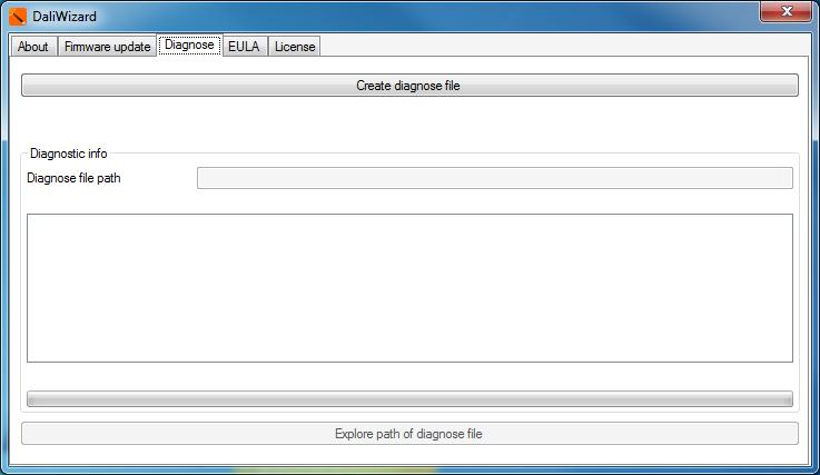
31 Control gear according to IEC , device type 8, optical control. Participants detected as an OSRAM product are shown in colour, competitor devices or older OSRAM devices are shown on a grey background. Device group: Groups according to DALI Standard IEC are marked with this symbol. Interface symbols "Execute": Clicking on a button marked as such leads to execution of an action. Example: Transfer of a light value to a control gear. "Query": Clicking on a button marked as such leads to the querying of one or more parameters of a control gear. Example: Query for a lamp failure. "Transmit configuration": Clicking on a button marked as such leads to the transfer of one or more parameters to a control gear. Example: Saving a scene light value. "Cancel": Cancels a prolonged action immediately. "Yes" indicator: Appears if an associated request has been answered with "Yes". "No" indicator: Appears if an associated request has been answered with "No". "Undetermined indicator": Appears if multiple control gears are selected, but have different values. "Unknown" indicator: Appears if a parameter is unknown or if the answer to a question cannot be clearly interpreted, e.g. if several participants respond at the same time. Movement detector switches on. Movement detector switches off. Program and manual updates Please note: All information in this manual has been prepared with great care. OSRAM, however, does not accept liability for possible errors, changes and/or omissions. Please check or contact your sales partner for an updated copy of this manual. Software updates: To ensure the latest software version is used please consult the OSRAM website in regular intervals (once a month). New versions will be released due to software improvements, additional supported devices and bug fixing. 31
32 Appendix DALI Wizard End User Licence Agreement Software product: DALI wizard Licenser: OSRAM GmbH LICENSE CONDITIONS FOR DALI wizard PC SOFTWARE This is an End User Licence Agreement between you, the end user, and the OSRAM GmbH, Marcel-Breuer-Straße 6, D Munich, Germany (hereinafter called "OSRAM"). By accepting this End User Licence Agreement you are bound by the conditions contained in it. I. Granting of the licence This End User Licence Agreement grants you the non-exclusive and non-transferable right to use the DALI wizard Software on any computer. You may make several copies of the DALI wizard Software in order to use it on several computers. II. Copyright, property rights The DALI wizard Software is property of OSRAM and protected by copyright laws, international treaties and further national laws. Product manuals or other written documents accompanying the DALI wizard Software may not be copied without OSRAM s written consent. The word and design mark OSRAM, other product trademarks, pictures or logos identify OSRAM products and are protected trademarks of OSRAM. The use of these trademarks shall only be allowed with the permission of OSRAM. The use of the name OSRAM shall only be allowed as reference, for example for connection with the DALI wizard Software. For such a use, OSRAM has to be informed previously. No licence or right to any patent, trademark or any other industrial property right of the OSRAM GmbH shall be granted silently or in any other way by means of this End User Licence Agreement. Furthermore, no licence or any right to a copyright or any other rights shall be granted unless this is expressly mentioned in this End User Licence Agreement. III. Further restrictions The DALI wizard Software must not be distributed, leased or in any other way be let by you to third parties. Unless otherwise permitted by imperative legal regulations, you must not change, redevelop or retranslate the software or parts thereof. IV. No liability for consequential damage In case of intention or gross negligence for whatever legal ground OSRAM shall only be liable pursuant to the legal provisions. Likewise, OSRAM shall only be liable for claims for compensation due to injury to health, body or life and for claims due to the provisions of the product liability law pursuant to the legal regulations. In case of accepting a warranty of quality or due to fraudulent concealment of a defect, OSRAM shall be liable pursuant to the legal provisions. If OSRAM violates a material obligation or a cardinal obligation culpably, the liability shall be limited to the compensation for the typically occurring, foreseeable damage. The same shall apply if the customer is entitled to claims for substitution of the damage instead of performance. Unless otherwise regulated above, any claims for damages against OSRAM shall be excluded. V. Export control The export of certain information, software and documentation may e.g. due to their type or their intended purpose or final whereabouts be subject to the duty to obtain a permit. You have to strictly observe the relevant export regulations for information, software and documentation, especially the regulations of the EU and/or the member states of the EU as well as the ones of the USA. OSRAM labels information, software and documentation regarding the duty to obtain a permit pursuant to the German and the EU export list as well as the US Commerce Control List. 32
Application note. WAGO-I/O-SYSTEM 750 DALI Multi-Master Module Configuration of a DALI Lighting System via WAGO- I/O-PRO V2.
 Application note WAGO-I/O-SYSTEM 750 DALI Multi-Master Module 753-647 Configuration of a DALI Lighting System via WAGO- I/O-PRO V2.3 Visualization Version: 25.06.2015 2 Imprint 2015 by WAGO Kontakttechnik
DALI Link User Manual
 1.Overview Digital Addressable Lighting Interface (DALI) is a communication protocol for lighting control in buildings. The interface was first described in the IEC60929 standard for fluorescent lamp ballast,
Contents. GAMMA instabus Application program - Descriptions. June B0 KNX / DALI Gateway Twin N 141/
 Contents 1. Product description...2 1.1 DALI fundamentals...2 1.2 Gateway fundamentals...2 2. Functional overview...2 2.1 Modes... 3 2.1.1 Normal mode... 3 2.1.2 Standalone mode... 3 2.1.3 Direct mode...
GXLink MultiChannel Wave Inserter Model SP-631
 800173-0A Digital High Speed GXLink MultiChannel Wave Inserter Model SP-631 User Manual Copyright 2009 It is prohibited to copy, reproduce or distribute this information in whole or in part without the
SINAMICS G/S: Tool for transforming Warning and Error Messages in CSV format
 Application example 03/2017 SINAMICS G/S: Tool for transforming Warning and Error Messages in CSV format https://support.industry.siemens.com/cs/ww/en/view/77467239 Copyright Siemens AG 2017 All rights
Solare Datentechnik SUNNY DESIGN
 Solare Datentechnik SUNNY DESIGN User Manual SDesign-BEN082215 Version 1.5 EN Table of Contents Table of Contents 1 Notes on this Manual.............................. 4 1.1 Target Group.......................................
Communication between HMI and Frequency Converter. Basic Panel, Comfort Panel, Runtime Advanced, SINAMICS G120. Application Example 04/2016
 Application Example 04/2016 Communication between HMI and Frequency Converter Basic Panel, Comfort Panel, Runtime Advanced, SINAMICS G120 https://support.industry.siemens.com/cs/ww/en/view/109481157 Warranty
DALI Professional Frequently asked questions Light is OSRAM
 www.osram.com DALI Professional Frequently asked questions Light is OSRAM DALI PROFESSIONAL Frequently Asked Questions What is the max. cable length in OSRAM DALI PROFESSIONAL system? Is it 300 m in total
Manual. Software Protection. TwinCAT 3. Version: Date:
 Manual Software Protection TwinCAT 3 Version: Date: 1.7 2018-10-25 Table of contents Table of contents 1 Foreword... 5 1.1 Notes on the documentation... 5 1.2 Safety instructions... 6 2 Introduction...
Drive System Application
 Drive System Application Generating application macros Application description for SINAMICS G and MICROMASTER 4 Warranty, liability and support Note The Application Examples are not binding and do not
https://support.industry.siemens.com/cs/ww/en/view/
 Setup a new Process Historian with an existing Historian Storage Database SIMATIC Process Historian 2013/2014 https://support.industry.siemens.com/cs/ww/en/view/66579062 Siemens Industry Online Support
ISTA User instructions for the BMW Online Service System for BMW Service and MINI Service (OSS)
") ISTA User instructions for the BMW Online Service System for BMW Service and MINI Service (OSS) Release 1.0 Technical documentation and diagnosis BMW Group Page 2 Contents 1 Introduction......... 4 1.1
ISTA User instructions for the BMW Online Service System for BMW Service and MINI Service (OSS) Release 1.0 Technical documentation and diagnosis BMW Group Page 2 Contents 1 Introduction......... 4 1.1
TROVIS-VIEW 4 Software TROVIS Operating Instructions EB 6661 EN. Electronics from SAMSON
 TROVIS-VIEW 4 Software TROVIS 6661 Operating Instructions Electronics from SAMSON EB 6661 EN Edition January 2015 Definition of signal words DANGER! Hazardous situations which, if not avoided, will result
DALI Cockpit. Startup Guide V5. DALI Configuration Tool. Traffic Monitoring. 2017/12/15, Lunatone Industrielle Elektronik GmbH DALI Cockpit
 DALI Cockpit Startup Guide V5 DALI Configuration Tool Commissioning of DALIcomponents and DALI-line Traffic Monitoring 2017/12/15, Lunatone Industrielle Elektronik GmbH DALI Cockpit 2 DALI Cockpit Configuration
Drive System Application
 Drive System Application Application Description Uploading and downloading drive parameters of a xx using STARTER Table of Contents Table of Contents 1 Warranty, liability and support... 3 2 Description...
PRESENCE DETECTOR, CONSTANT LIGHT CONTROLLER PD00D01KNX. Product Handbook
 PRESENCE DETECTOR, CONSTANT LIGHT CONTROLLER PD00D01KNX Product Handbook Product: PD00D01KNX Description: PRESENCE DETECTOR, CONSTANT CONTROLLER Document Version: 1.3 Date: 03/10/2017 Tribunale di Mila
BNI USB A501. USB IO-Link Master User's Guide. english
 User's Guide english 1 2 4 Notes to the user 1.1 About this guide 1.2 Structure of the guide 1. Typographical conventions 1.4 Symbols 1.5 Abbreviations Safety 4 2.1 Intended use 4 2.2 General safety notes
Software Manual ifm Vision Assistant for 3D camera O3X1xx
 Software Manual ifm Vision Assistant for 3D camera O3X1xx UK 706446 / 00 07/2017 Content 1 Preliminary note... 4 1.1 Symbols used... 4 1.2 Safety instructions... 4 1.3 Further documents... 4 2 System requirements...
AMB8466-M-GMS Konfigurator version 1.1
 Users Guide AMB8466-M-GMS Konfigurator version 1.1 Abbreviations USB - Universal Serial Bus wm-bus - wireless M-BUS M-BUS - Meter-Bus (wired) DLMS - Device language message specification (http://www.dlms.com)
AWLaunch. Software Manual. Version 1.2 Last Revised April 27, 2009
 AWLaunch Software Manual Version 1.2 Last Revised April 27, 2009 All contents in this manual are copyrighted by ArWest Communications. All rights reserved.the information contained herein may not be used,
DALI Professional Controller-4. Control unit Operating instructions
 LI Professional Controller-4 Control unit Operating instructions Contents Safety... 4 General instructions 4 Safety instructions 4 Description... 5 Purpose and application 5 Configuration 5 Design 5 Connections
Instruction manual. testo easyemission Software
 Instruction manual testo easyemission Software en 2 General Information General Information This documentation includes important information about the features and application of the product. Please read
DALI x/e-touchpanel 02. Product manual
 DALI x/e-touchpanel 02 Product manual Table of Contents Table of contents 1 Validity........................................................................ 4 1.1 Copyright.............................................................................
Device Programming using TRWinProg
 Device Programming using TRWinProg Software No.: _490-00416 _490-00416_WIN7 _Program Summary _Safety instructions _System requirements _Program installation _Connecting devices to the PC _Program start
Ozone Toolset PC software User Manual
 Ozone Toolset PC software User Manual 1 Introduction The high grade of intelligence and flexibility behind OZONE led driver and the Living Energy philosophy undertaken by ROAL, permitted us to develop
MultiOne. Getting started
 MultiOne Philips Lighting B.V. 2015 1 Introduction- MultiOne Engineering 2.7 This guide covers the following topics to help you start using MultiOne: The MultiOne system The MultiOne software Working with
Agilent 34826A BenchLink Data Logger for 34980A. Getting Started Guide. Agilent Technologies
 Agilent 34826A BenchLink Data Logger for 34980A Getting Started Guide Agilent Technologies Notices Agilent Technologies, Inc. 2006 No part of this manual may be reproduced in any form or by any means (including
USER MANUAL 1 OZONE TOOLSET PC SOFTWARE SW VERSION V Ozone ToolSet PC Software User Manual
 Ozone ToolSet PC Software User Manual www.efore.com Page 1 UM1_Ozone ToolSet_Rev06, June 2016 Table of Contents 1. Introduction... 3 2. Minimum PC Requirements and License Agreement... 4 3. Software Installation
PRODUCT GUIDE. L e p i d e S o f t w a r e P r i v a t e L i m i t e d
 PRODUCT GUIDE Table of Contents 1. About Kernel for PDF to Word... 4 1.1 Using this Manual... 4 1.2 Kernel for PDF to Word... 5 1.4 Who Should Use this Software?... 6 2. Getting Started... 7 2.1 Installation
Display of SINAMICS Error Messages in Runtime Professional
 Application Example 09/2016 Display of SINAMICS Error Messages in Runtime Professional SINAMICS G120, WinCC Runtime Professional https://support.industry.siemens.com/cs/ww/en/view/109738320 Warranty and
Operating manual. UNIData1100. Data transfer software for data exchange between a PC and UNIMET 1000/1100ST
 Operating manual UNIData1100 Data transfer software for data exchange between a PC and UNIMET 1000/1100ST Power in electrical safety TGH1391en/07.2005 Manufacturer: Distribution: Dipl.-Ing. W. Bender GmbH
User and Installation Manual PC-DMIS Operator Interface Version X.X
 PC-DMIS Operator Interface Version 2.2010.X.X 2009-2012 Hexagon Metrology GmbH Germany Table of Contents 1 General information... 4 1.1 Software objectives... 4 1.2 Software requirements... 4 1.3 License
Installation Instructions
 Dual EIB bus coupler Order no.: 1246 651, 1246 661, 1246 671 rmation The Gira SmartSensor is a product of the Instabus KNX/EIB System and complies with KNX/EIBA directives. The functions of the device
Release Notes masterconfigurator
 Release Notes masterconfigurator Release Note masterconfigurator V2.30.0.70 Detect and clear of double addressing New features implemented (ITG-Offset, CLO2, ETM, inputdim) DT8: change of physical MIN/MAX
Topology Reporter Tool Description April 2012 Applications & Tools Answers for industry.
 Cover Creating Documentation Components for PROFINET IO Networks Tool Description April 2012 Applications & Tools Answers for industry. Siemens Industry Online Support This article is taken from the Siemens
HLC-IPDRV Tridium Helvar IP Driver. Installation and User Guide. Doc. No. D Iss. 3
 HLC-IPDRV Tridium Helvar IP Driver Installation and User Guide Doc. No. D005247 Iss. 3 HLC-IPDRV Tridium - Helvar IP Driver Table of Contents 1 Revision History... 3 2 Document Outline... 3 3 Scope...
Service & Support. Data Transfer from the SIPLUS CMS2000 TCP/IP Data Interface to an S7-300CP SIPLUS CMS2000. Application Example May 2012
 Cover Sheet Data Transfer from the SIPLUS CMS2000 TCP/IP Data Interface to an S7-300CP SIPLUS CMS2000 Application Example May 2012 Service & Support Answers for industry. Warranty and Liability Warranty
Comfort software x35 Professional. Instruction manual. testo x35 Professional
 Comfort software x35 Professional Instruction manual en testo x35 Professional Licence Agreement This is a legally binding contract between you, as the end user, and Testo. Once you or another authorised
PRODUCT GUIDE. N u c l e u s D a t a R e c o v e r y. C o m P r i v a t e L i m i t e d
 PRODUCT GUIDE Table of Contents 1. About Kernel for PST Split... 4 1.1 Using this Manual... 4 1.2 Introduction to Kernel for PST Split... 4 1.3 Key Features... 5 1.4 System Requirements... 5 2. Understanding
Applications & Tools. Block for STEP 7 V5.5 for monitoring 24 V DC load circuits using SITOP PSE200U Single Channel Message and S7-300/400 CPUs
 Cover Block for STEP 7 V5.5 for monitoring 24 V DC load circuits using SITOP PSE200U Single Channel Message and S7-300/400 CPUs SIMATIC S7 / SITOP PSE200U with Single Channel Message Library Description
Stellar Phoenix Windows Data Recovery - Pro
 Stellar Phoenix Windows Data Recovery - Pro Version 4.2 Installation Manual 1 Overview Stellar Phoenix Windows Data Recovery is a complete solution to recover data from hard disk. However, Microsoft Windows
OT EASY 60 II. LED control unit Operating instructions
 II LED control unit Operating instructions Contents Safety... 4 General instructions 4 Safety instructions 4 Intended use 4 Description... 5 Function and application 5 Function 5 Important definitions
MultiOne. Getting started. Copyright 2016 Philips Lighting Holding B.V.. All Rights Reserved
 MultiOne Getting started Copyright 2016 Philips Lighting Holding B.V.. All Rights Reserved 1 Introduction This Getting started guide covers the following topics to help you start using MultiOne: The MultiOne
Application description
 Manufacturer Berker Motion detector Application description KNX motion detector module comfort 1.10m KNX motion detector module comfort 2.20m ETS KNX motion detector module comfort 1.10m ETS KNX motion
User s Guide. Controller. Be sure to keep all user documentation handy for future reference.
 E User s Guide Controller Be sure to keep all user documentation handy for future reference. Read this first! The contents of this User s Guide are subject to change without notice. Copying of this manual,
User Manual. HOPPECKE sun powerpack premium. service software
 User Manual HOPPECKE sun powerpack premium service software Contents 1. INTRODUCTION 4 2. TARGET GROUP 4 3. MEANS OF REPRESENTATION 4 4. BASIC INFORMATION FOR APPLICATION USE 5 4.1. System requirements
KNX DALI Gateway Plus - User Manual
 KNX DALI Gateway Plus - User Manual Item No.: LC-013-064 1. Product Description The KNX DALI gateway Plus is the interface between the KNX installation and the DALI lighting system. It allows up to 64
M2500 Engine Controller Configuration Manual
 M2500 Engine Controller Configuration Manual Revision: 08-04-2011 Page 1 Contents 1 Preface... 4 2 Configuration from front panel... 5 2.1 Engine Controller Configuration... 6 2.1.1 RPM settings... 6 2.1.2
Introduction to the Autologic Vehicle Diagnostic Tool
 Introduction to the Autologic Vehicle Diagnostic Tool User Instructions Version 4.0 Issued April 2012 For the latest version of this document see www.autologic.com Ltd has made every effort to make sure
Operation Manual. for the. Data Logging Software. Version 7.1. (Isoft.xls)
") for the Data Logging Software Version 7.1 (Isoft.xls) TetraTec Instruments GmbH 1 GENERAL HINTS 1.1 Typographical Conventions Displayment Means marks a work procedure, which you must implement references
for the Data Logging Software Version 7.1 (Isoft.xls) TetraTec Instruments GmbH 1 GENERAL HINTS 1.1 Typographical Conventions Displayment Means marks a work procedure, which you must implement references
Operating instructions
 Operating instructions DALI BASIC lighting control system Type: DALI RC BASIC SO 24.05.2001 / V1.0 OSRAM GmbH Hellabrunner Str. 1 D 81536 Munich Tel.: +49 89 6213 0 Fax: +49 89 6213 2020 Customer Service
Applications & Tools. Service Concept: Auto Backup for the Comfort Panels. WinCC (TIA Portal) V12. Application Description May 2013
 V12. Application Description May 2013") Cover Service Concept: Auto Backup for the Comfort Panels WinCC (TIA Portal) V12 Application Description May 2013 Applications & Tools Answers for industry. Copyright Siemens AG 2013 All rights reserved
Cover Service Concept: Auto Backup for the Comfort Panels WinCC (TIA Portal) V12 Application Description May 2013 Applications & Tools Answers for industry. Copyright Siemens AG 2013 All rights reserved
Block for SIMOTION SCOUT for Monitoring 24V-Branches
 Application description 12/2013 Block for SIMOTION SCOUT for Monitoring 24V-Branches SIMOTION CPU / SITOP PSE200U with Single Channel Message http://support.automation.siemens.com/ww/view/en/82555461 Warranty
E600 VX01 Installation guide
 E600 VX01 Installation guide illuminfx Dimensions 2007 Viso Systems ApS, Denmark All rights reserved. No part of this manual may be reproduced, in any form or by any means, without permission in writing
Installation and User Manual. PV Manager Offline
 Installation and User Manual PV Manager Offline Version 1.0 as of: 03/30/2016 1 Disclaimer We worked very carefully to compile these texts and figures. However, we cannot fully eliminate the possibility
SICAM SICAM FCM Configurator
 Preface Open Source Software SICAM SICAM FCM Configurator Table of Contents SICAM FCM Configurator 1 Index V02.10 Configuration and Operation E50417-H8940-C592-A3 i NOTE For your own safety, observe the
DTM for Hilscher DeviceNet Master Devices
 tgg Operating Instruction Manual DTM for Hilscher DeviceNet Master Devices Configuration of Hilscher Master Devices Hilscher Gesellschaft für Systemautomation mbh www.hilscher.com DOC070403OI12EN Revision
Helvar Designer 5 Foundation Course: Initial programming
 Helvar Designer 5 Foundation Course: Initial programming Edition 1 (10 th May 2018). Helvar Designer 5 Foundation Course: Initial Programming. Edition 1 Page 1 of 99 Contents A: BEFORE GOING ONLINE...
 Acknowledgement of WinCC Messages with forced comments WinCC V7 https://support.industry.siemens.com/cs/ww/en/view/52329908 Siemens Industry Online Support Warranty and liability Warranty and liability
efesotomasyon.com - Lenze Manual Global Drive PC system bus adapter 2173 / 2177 Software installation & configuration
 L Manual Global Drive PC system bus adapter 2173 / 2177 Software installation & configuration CAUTION: The software is supplied to the user as described in this document. Any risks resulting from its quality
Software WINDY BOY Setup Tool
 Software WINDY BOY Setup Tool User Manual WBSetup-BEN100411 Version 1.1 EN Table of Contents Table of Contents 1 Notes on this Manual.............................. 5 1.1 Area of Validity......................................
C A S P E R USER GUIDE V ERSION 10
 TM C A S P E R TM USER GUIDE V ERSION 10 Copyright and Trademark Information Information in this document is subject to change without notice. Federal law prohibits unauthorized use, duplication, and distribution
Manual Light Driver 5.0
 1 Manual Light Driver 5.0 2 Content Change History... 3 Product description... 4 Specifications... 5 Measurements... 6 Layout and connection assignment... 7 Start-up... 8 Factory settings... 8 Individual
Date Revision Change(s) 10/10/ First version
 10/10/ First version") Revision overview Revision overview Date Revision Change(s) 10/10/2017 0 First version Copyright 2017 Indu-Sol GmbH We reserve the right to amend this document without notice. We continuously work on further
Revision overview Revision overview Date Revision Change(s) 10/10/2017 0 First version Copyright 2017 Indu-Sol GmbH We reserve the right to amend this document without notice. We continuously work on further
GpsSimul User Guide 1. GpsSimul User Guide. User guide. (c) 2012 Sailsoft
 2012 Sailsoft") GpsSimul User Guide 1 GpsSimul User Guide User guide GpsSimul User Guide 2 Table of Contents GpsSimul User Guide... 3 Welcome to GpsSimul... 4 Licensing GpsSimul... 5 GpsSimul License... 5 Introduction...
GpsSimul User Guide 1 GpsSimul User Guide User guide GpsSimul User Guide 2 Table of Contents GpsSimul User Guide... 3 Welcome to GpsSimul... 4 Licensing GpsSimul... 5 GpsSimul License... 5 Introduction...
Manual for DMX-60 Controller Box and Software 1 Introduction 1.1 Software Installation
 Manual for DMX-60 Controller Box and Software 1 Introduction What actually is DMX512? DMX is short for "Digital Multiplex" and is a digital data transmission standard for dimmers, scanners, and their controllers.
COMMERCIAL BANK OF DUBAI PSC GENERAL CONDITIONS OF ACCESS AND USE OF COMMERCIAL BANK OF DUBAI FACEBOOK BRANCH
 COMMERCIAL BANK OF DUBAI PSC GENERAL CONDITIONS OF ACCESS AND USE OF COMMERCIAL BANK OF DUBAI FACEBOOK BRANCH 1. CBD Facebook Branch Commercial Bank of Dubai psc (hereinafter "CBD"), allows access and
System CPX-E. IO-Link master module CPX-E-4IOL- Description. Protocol IO-Link. Function Parameterisation [ ]
![System CPX-E. IO-Link master module CPX-E-4IOL- Description. Protocol IO-Link. Function Parameterisation [ ]](/thumbs/81/83977214.jpg "System CPX-E. IO-Link master module CPX-E-4IOL- Description. Protocol IO-Link. Function Parameterisation [ ]") System CPX-E IO-Link master module CPX-E-4IOL- Description Protocol IO-Link Function Parameterisation 877 27-7 [879] IO-Link master module CPX-E-4IOL- Original instructions CPX-E-4IOL- -E N IO-Link is
System CPX-E IO-Link master module CPX-E-4IOL- Description Protocol IO-Link Function Parameterisation 877 27-7 [879] IO-Link master module CPX-E-4IOL- Original instructions CPX-E-4IOL- -E N IO-Link is
SIMATIC Energy Suite Visualization example of the "*.csv"-energy Data Files
 Application Example 03/2017 SIMATIC Energy Suite Visualization example of the "*.csv"-energy Data Files SIMATIC STEP 7 (TIA Portal), SIMATIC Energy Suite https://support.industry.siemens.com/cs/ww/en/view/109739772
Service & Support. Signal Transfer from SIPLUS CMS4000 X-Tools to the SIMATIC PCS 7 Maintenance Station via TCP/IP. SIPLUS CMS4000 X-Tools
 Cover sheet Signal Transfer from SIPLUS CMS4000 X-Tools to the SIMATIC PCS 7 Maintenance Station via TCP/IP SIPLUS CMS4000 X-Tools Application Example March 2011 Service & Support Answers for industry.
1 Safety instructions. 2 Device components. 3 Function. IC00P01DAL - DALI gateway. DALI gateway. Operating instructions
 DALI gateway Operating instructions 1 Safety instructions Electrical equipment may only be installed and fitted by electrically skilled persons. Serious injuries, fire or property damage possible. Please
Manual SmartGraph for Humlog 10
 Manual SmartGraph for Humlog 10 State: 10.12.2001 Version: V1.0 1 1 INTRODUCTION TO SMARTGRAPH... 4 1.1 Manage, Configure... 4 1.2 The Programme Interface... 4 1.2.1 Graphs... 5 1.2.2 Table... 6 1.2.3
TROVIS-VIEW 4 Software TROVIS Operating Instructions EB 6661 EN. Electronics from SAMSON
 TROVIS-VIEW 4 Software TROVIS 6661 Operating Instructions Electronics from SAMSON EB 6661 EN Edition August 2017 Definition of signal words DANGER! Hazardous situations which, if not avoided, will result
SINAMICS G/S: Integrating Warning and Error Messages into STEP 7 V5.x or WinCC flexible
 Application Example 03/2017 SINAMICS G/S: Integrating Warning and Error Messages into STEP 7 V5.x or WinCC flexible https://support.industry.siemens.com/cs/ww/en/view/77467239 Warranty and Liability Warranty
Electrical devices may only be mounted and connected by electrically skilled persons.
 DALI gateway TW Art. No. : 2099REGHE Operating instructions 1 Safety instructions Electrical devices may only be mounted and connected by electrically skilled persons. Serious injuries, fire or property
https://support.industry.siemens.com/cs/ww/en/view/
 Application to support the acceptance test of the Safety Integrated Functions of SINAMICS G120 SINAMICS G / Safety https://support.industry.siemens.com/cs/ww/en/view/73102423 Siemens Industry Online Support
TotalShredder USB. User s Guide
 TotalShredder USB User s Guide Copyright Notice No part of this publication may be copied, transmitted, stored in a retrieval system or translated into any language in any form or by any means without
SCHMIDT Programming Tool SS 20.4xx Instructions for Use
 SCHMIDT Programming Tool SS 20.4xx Instructions for Use SCHMIDT Programming Tool SS 20.4xx Table of Contents 1 Important Information... 3 2 Field of Application... 4 3 Scope of Delivery... 4 4 Programming
PHARO User Configuration Software UCS USER MANUAL Rev.0-15/07/ pharo.reer.it
 PHARO User Configuration Software UCS USER MANUAL 8540588 - Rev.0-15/07/2004 www.reer.it pharo.reer.it This document is protected by the law of copyright, whereby all rights established therein remain
BQS User Guide For Online (Hosted) Approved Centres
 Approved Centres") BQS User Guide For Online (Hosted) Approved Centres April 2013 v3.0 Contents 1. Getting Started... 3 1.1 Administration... 3 1.2 Automated Testing Software... 3 2. BQS Web Administration... 4 2.1 The Login
BQS User Guide For Online (Hosted) Approved Centres April 2013 v3.0 Contents 1. Getting Started... 3 1.1 Administration... 3 1.2 Automated Testing Software... 3 2. BQS Web Administration... 4 2.1 The Login
Networking a SINUMERIK 828D
 Application description 06/2015 828D SINUMERIK 828D, SW 4.5 SP3 https://support.industry.siemens.com/cs/ww/en/view/109474567 Warranty and liability Warranty and liability Note The Application Examples
FLOWgate500. Software Manual. Software Manual FLOWgate500 Release 2.2. Revision number: V2.2. Manufacturer: SICK AG. Erwin-Sick-Str.
 FLOWgate500 Software Manual Software Manual FLOWgate500 Release 2.2 Revision number: V2.2 Manufacturer: SICK AG Erwin-Sick-Str.1 D-79183 Waldkirch Germany Place of manufacture: SICK Engineering GmbH Bergener
Multi Battery Charger MBC-08. Manual
 Multi Battery Charger MBC-08 Manual Imprint Information in this document is subject to change without notice. No part of this document may be reproduced or transmitted without the express written permission
Welcome to ThinkEssentials
 User s Manual Welcome to ThinkEssentials Figure 1: Sample room and device layout with ten devices ThinkEssentials software includes the following features: Set up and control up to 230 Z-Wave devices Draw
Application description. KNX Push-button module 1gang. KNX Push-button module 2gang
 Application description KNX Push-button module 1/2gang Electrical/mechanical data: see the operating instructions for the product Order number Product designation Application programme TP product Radio
INSTRUCTION MANUAL. IBREXDLL Software for MS Excel. M e t r o l o g y. Messtechnik GmbH & Co. KG
 M e t r o l o g y INSTRUCTION MANUAL Software for MS Excel Document No. : D2MF710 001 Edition : April 2009 Copyright : IBR Messtechnik GmbH & Co. KG Contents 1. Introduction... : 3 2. Features... : 3 3.
Administration guide. PRISMAprepare
 Administration guide PRISMAprepare Edition 2016-10 GB Contents Contents Chapter 1 Licences... 5 Copyright...6 Trademarks... 7 Licences...8 Software version... 8 Manage the licence... 9 Chapter 2 Printer
SWISS GARDE 360 HOKUSPOKUS KNX/KLR APPLICATION DESCRIPTION
 SWISS GARDE 360 HOKUSPOKUS KNX/KLR APPLICATION DESCRIPTION MODEL TYPE NO. SG HOKUSPOKUS KNX/KLR 25010 Program version 2.7 2012 M. Züblin AG Neue Winterthurerstrasse 30, 8304 Wallisellen, Switzerland The
Contents. GAMMA instabus Application program description. August 2017
 Contents 1. Product description 4 1.1 DALI fundamentals... 4 1.2 Gateway fundamentals... 4 2. Functional overview of both devices 5 2.1 Modes... 5 2.2 Replace defective DALI-ECGs... 7 2.3 Failure messages
Meso LED Driver stands for an extremely flexible LED Driver, designed for fast and easy configuration.
 Introduction Meso LED Driver stands for an extremely flexible LED Driver, designed for fast and easy configuration. This Application Note AN3_ illustrates the setting options of the Meso LED driver in
Serial ATA PCI RAID Quick Installation Guide
 Serial ATA PCI RAID Quick Installation Guide Introducing the Serial ATA PCI RAID The Serial ATA PCI RAID is an ultra high-speed two channel Serial ATA controller board for use in Pentium-class computers.
Content 1 Generally Installation...3
 Content 1 Generally...2 2 Installation...3 2.1 ETS App...3 2.2 Documentation and sample project...3 3 User interface...4 4 XLSX-Excel-Template...5 4.1 General...5 4.2 Mass operation...5 4.3 Errors during
Safe and Fault Tolerant Controllers
 Safe and Fault Tolerant Controllers SIMATIC Safety Integrated for Process Automation Wiring and Evaluation Architectures for Failsafe Digital Input (F-DI)- and Output-Modules (F-DO) of ET 200M Functional
X-618 Public Address and Voice
 X-618 Public Address and Voice Alarm System Commissioning Manual M_XXXXXX_CN_0 Copyright 2012 Honeywell International Inc. All rights reserved. No part of this document may be reproduced in any form without
Production feedback via WinCC Data Transfer with XML file
 Application Example 09/2016 Production feedback via WinCC Data Transfer with XML file WinCC/IndustrialDataBridge V7.4, SIMATIC WinCC V7 https://support.industry.siemens.com/cs/ww/en/view/109483465 Warranty
Beta Testing Licence Agreement
 Beta Testing Licence Agreement This Beta Testing Licence Agreement is a legal agreement (hereinafter Agreement ) between BullGuard UK Limited ( BullGuard ) and you, either an individual or a single entity,
Manual for DMX-120 Controller Box and Software
 Manual for DMX-120 Controller Box and Software 1 Introduction What actually is DMX512? DMX is short for "Digital Multiplex" and is a digital data transmission standard for dimmers, scanners, and their
Exchange of large data volumes between S control system and WinCC
 Application Example 09/2016 Exchange of large data volumes between S7-1500 control system and WinCC S7-1500, WinCC V7.4 https://support.industry.siemens.com/cs/ww/de/view/37873547 Warranty and Liability
Stellar WAB to PST Converter 1.0
 Stellar WAB to PST Converter 1.0 1 Overview Stellar WAB to PST Converter software converts Outlook Express Address Book, also known as Windows Address Book (WAB) files to Microsoft Outlook (PST) files.
Virtual CD TS 1 Introduction... 3
 Table of Contents Table of Contents Virtual CD TS 1 Introduction... 3 Document Conventions...... 4 What Virtual CD TS Can Do for You...... 5 New Features in Version 10...... 6 Virtual CD TS Licensing......