Optimisationfor CFD. ANSYS R14 Fluids Update Seminar. Milton Park, February 16 th, 2012 Sheffield, February 29 th, 2012 Aberdeen, March 8 th, 2012
|
|
|
- Madlyn Robbins
- 5 years ago
- Views:
Transcription


1 Optimisationfor CFD ANSYS R14 Fluids Update Seminar David Mann, ANSYS UK Ltd. Milton Park, February 16 th, 2012 Sheffield, February 29 th, 2012 Aberdeen, March 8 th,
 Mesh Morpher or Shape Optimiser RBF-Morph AdjointSolver Remote Solve Manager (RSM)")
2 Agenda Optimisation Tools for CFD Introduction Manual Optimisation and Scripting Design Xplorer(DX) Mesh Morpher or Shape Optimiser RBF-Morph AdjointSolver Remote Solve Manager (RSM) Summary 2
3 Introduction I have run my analysis, but.. What happens if I increase/reduce the flow rate? What do I need to adjust to unify the flow distribution? How should the geometry change to maximise heat rejection? What can be to done to mix out the species earlier? Which parameters have greatest effect on the pressure drop? What actions can I take to prevent the coolant from boiling? How do I optimisemy design. 3
4 Introduction Optimisationrefers to seeking the best possible design point within the design space Optimisation is a three-fold problem Formulation of appropriate parameterisation Parametric geometry using CAD tool or Design Modeler Mesh morpher to define parametric mesh deformations Selection of objective function What are we seeking to maximiseor minimise Selection of robust optimiser Gradient based optimisation method (Adjoint Solver) Direct search based optimisation method (e.g. Simplex Method) Statistical Optimisation method (ANSYS DesignXplorer) 4


5 ANSYS provides a comprehensive set of tools for optimisation Manual part mesh replacement Design of Experiments Response Surfaces Goal Seek Mesh Morphing Introduction Adjoint Solutions Optimisation can be based around parametric geometry, arbitrary freeform mesh deformation, or precise geometrical mesh deformation 5
6 Agenda Optimisation Tools for CFD Introduction Manual Optimisation and Scripting Design Xplorer(DX) Mesh Morpher or Shape Optimiser RBF-Morph AdjointSolver Remote Solve Manager (RSM) Summary 6
7 Manual Optimisation Replace sub zones effectively as parameter for design points. New in R14. Allows automatic first order interpolation of face and cell data Allows automatic grid manipulations (face slitting, node merging, zone fusing, recreation of mesh interfaces etc) Can use apriorigrid preparation/decomposition but also works well with cavity re-meshing tool in TGrid for conformal interfaces Only requires re-meshing of sub zones (replaced part) and larger mesh can be re-used across design points Able to cope with large design changes and topology changes (with consistent zone names) 7


8 Manual Optimisation Part Swapping : Six Each Cavity different wing remesh has wing slightly zone configurations for different conformal rotation, to sub-grid be compared position transplant and AoA 8


9 Manual Optimisation Transplant of meshes using script Design 2 Design 1 Design 3 Design 4 Design 5 Design 6 9

 Interpolate")
10 Manual Optimisation Example Script for the case Replace sub grid command Path to new sub grid Repeat for N designs New fluid zone name and zone to be replaced (need not be the same as here) Interpolate face/cell data? 10
11 Manual Optimisation Design1 Design 2 Design 3 Design 4 Design 5 Design 6 11

12 Manual Optimisation Design 1 Drag=97N Design 4 Drag=141N Design 2 Drag=137N Design 5 Drag=139N Design 3 Drag=131N Design 6 Drag=173N 12
13 Agenda Optimisation Tools for CFD Introduction Manual Optimisation and Scripting Design Xplorer(DX) Mesh Morpher or Shape Optimiser RBF-Morph AdjointSolver Remote Solve Manager (RSM) Summary 13

14 Gain Deeper Product Insights ANSYS simulation software can give you more clarity into your products and development processes Move from a single point solution to understanding the design space so simulation can guide design.??? 14 Single Point What If? Response Surface


15 Design Xplorer(DX) Workbench based optimisation tool Input and output parameters from all types of analysis can be shared with DX via WorkBench Works with all ANSYS products from ANSYS structural to EMAG to CFD, making it beneficial for multiphysics analysis 15


16 Example of DX usage Simple Diffuser To illustrate how Design Xplorercan be used to optimise a simple geometry consider the simple diffuser below:- The diffuser geometry is characterised by four input parameters This allows the diffuser s shape to be controlled by WorkBenchand Design Xplorer 16


17 Initial setup and run Current Design Point The initial run is setup and run as normal with CFD post then being used to provide output parameters This forms the current design point which can then be rerun with a different geometry simply by changing the input parameters, and the new results viewed via the output parameters 17


18 Design of Experiments (DoE) A Design of Experiments can then be used to automatically generate a set of runs which cover the design space specified by the parameters 18

19 Response Surface Results The data from the Design of Experiments runs is then used to generate a response surface from which the performance of other designs can be predicted A clear maximum pressure rise is visible in the results beyond which additional diffusion causes separation 19

20 Goal Driven Optimisation The response surface is used to predict the parameters that give the optimum design The objective function can be multi-variate, but in this case is simply chosen to maximise the pressure rise through the diffuser. Once determined the optimum design can be run to confirm the predicted results or to improve the resolution of the response surface 20
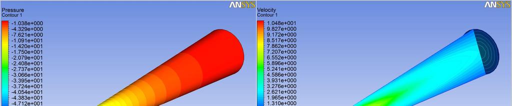
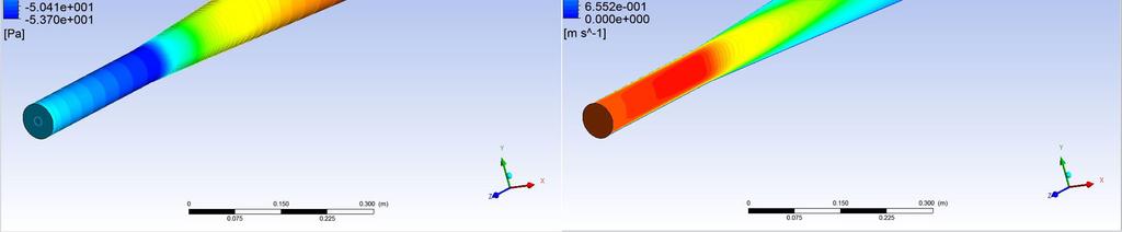
21 Confirmation Run Pressure Rise = Pa ( Pa predicted) 21
22 Design Xplorer(DX) DesignXplorer features the following studies: Design point analysis (default) -examines how the input parameters affect the output parameters by creating designs in a spreadsheet like view. Response Surface -Goal-Driven Optimization or GDO automatically change design parameters to find optimal design. -Six Sigma incorporates uncertainties of input parameters. Min-Max Search examines the entire output parameter space from a Response Surface to approximate the minimum and maximum of each output parameter. You can perform this search at any time. Parameter Correlation gives correlation data that has been used to derive sensitivities and decide if individual sensitivity values are significant or not. 22
23 Agenda Optimisation Tools for CFD Introduction Manual Optimisation and Scripting Design Xplorer(DX) Mesh Morpher or Shape Optimiser RBF-Morph AdjointSolver Remote Solve Manager (RSM) Summary 23

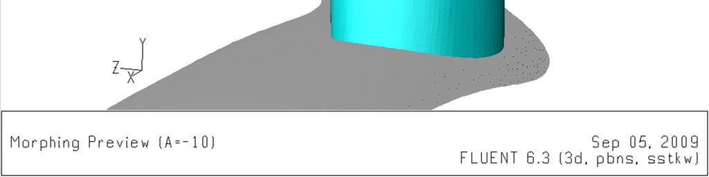
24 Introduction The mesh morphing technology introduced to ANSYS FLUENT at R13 allows a single mesh to be deformed in a freeform way to achieve new designs without the need to create new geometries or meshes. Thisgives us a platform on which we can carry out design optimisation studies without the need to build a parametric model on a topologically identical mesh. 24
25 Mesh Morpher Introduction The FLUENT Mesh Morpherutilizes Bernstein Polynomials to allow smooth mesh deformations based upon movement of predefined control points. The Morpheris hooked up to some basic optimization algorithms allowing shape optimization to be carried out within FLUENT with the following benefits: Shape modification carried out quickly in parallel solver Zero file I/O requirement Quick convergence -data from previous design point can be used for subsequent design points so initial data field is close to final solution Scriptable by Text User Interface journals Works on all mesh types, i.e. hex, tet, cutcell, hybrid, poly etc. 25


26 Mesh Morpher Case Study Manual Morphing Generic F1 car (Hexcore) nose extension before 26 Two control points moved in -x


27 Mesh Morpher Case Study Manual Morphing Generic F1 car (Hexcore) nose extension after 27 Two control points moved in -x

 28 A sufficient number of deformation modes will allow arbitrary shapes to be")
28 The morpher deformation modes In FLUENT the user specifies a deformation region inside which the mesh is morphed and an array of control points to define the deformation Modes of deformation are specified by describing how all the control points move together, for example the sine wave deformation shown Multiple deformation modes can be specified and the relative weighting of each controlled by parameters (three deformation modes = 3 parameters) 28 A sufficient number of deformation modes will allow arbitrary shapes to be formed


29 Mesh Morpher Interface Deformation Setup In R14 we now have the ability to constrain boundaries within deformation regions! 29
 in Design Xplorer(DX) requires script 2.")
30 Optimisation methods Design Xplorer Design of Experiments Internal FLUENT Simplex Optimiser Two different optimisation techniques are available when using the FLUENT morpher: Optimisation using Design of Experiments (DoE) in Design Xplorer(DX) requires script 2. Optimisation using one of the internal FLUENT Mesh MorpherOptimiser (MMO) methods such as the Simplex optimiser


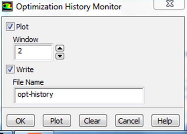
31 Mesh Morpher Optimiser 31
32 Mesh Morpher Objective Functions and Definition The Objective Function is a single scalar value that the chosen optimizer method will drive towards a minimum. Typical Objective Functions Lift & drag Mass flow-rate for inlets and outlets Surface average pressures for walls/inlets/outlets Min-max absolute pressure/temperature etc. Objective Function can be defined by: User defined functions Scheme Function NEW IN R14 GUI Driven Objective Function Definition that can call FLUENT exposed parameters 32
 2. Tumble home angle (θ 2 ) 3.")
33 Case Study 1 -Generic Sedan Drag Optimization Study effect of various vehicle shape parameters on drag force Shape parameters are defined using mesh morphing technology in ANSYS Fluent ANSYS WB is used to drive the shape parameters, create DOE & perform goal driven optimization ANSYS WB makes the process automatic Three Shape Parameters 1. Backlight angle (θ 1 ) 2. Tumble home angle (θ 2 ) 3. Windshield angle (θ 3 ) 33 Generic Sedan Model


34 Generic Sedan Baseline Design 34


35 Generic Sedan Worst Design 35

36 Generic Sedan Optimal Design 36


37 Case Study 2 Optimisation of NACA0012 The initial geometry to be optimised is the NACA0012 symmetrical 2D aerofoil section. A grid of 5 rows of 18 control points is superimposed over the mesh to facilitate the mesh morphing Moving these control points causes the mesh to morph A course tetmesh and a finer quad pave mesh were used Seek to maximise Lift to Drag ratio 37


38 Sine deformation modes applied to NACA 0012 section Mode n = sin(n.pi.x) where x is normalised between 0 and 1 from leading edge to trailing edge Mode 1 Mode 2 Mode 3 Mode 4 Mode 5 Mode 6 Mode o Mode o Mode o 38 Mode o Mode o Mode o

39 Workbench MorpherOptimisation Project Workflow Workbench and Design Xplorer are used to drive the six morpher parameters to optimise the design for lift/drag The workflow is shown below 39


40 Output parameters from CFD Post CFD Post is used to return the lift and drag from the aerofoil as Workbench output parameters A new workbench output parameter of Lift/Drag can then be derived in WB parameter manager for use in the DoE optimisation 40

41 Optimisation using Design Xplorer Data points using six morpherparameters are very noisy in their fit to the response surface, as there are always four other parameters not involved in the surface fit The response surface fit can be poor if the search area is wide, so the limits on parameters were tightened around the then best point and the DoE rerun several times to get a better fit 41


42 Optimisation using sine modes and inbuilt Simplex optimiser Convergence history using Simplex optimiser 42


43 Comparison of optimised aerofoil shapes with different optimisers Sine modes using DoE in Design Xplorer Sine modes using internal MMO simplex optimiser Parameters { , , , , , } C L /C D = , C L = , C D = Parameters { , , , , , } C L /C D = , C L = , C D = Interestingly two completely different sets of parameters were obtained giving very similar but laterally displaced aerofoil shapes with the same morpher modes The number of design points required were 3x 45 design points with DX and 148 with the MMO running the Simplex optimiser. DX required some manual refinement points. For the same C L /C D DX would have needed less. DX can spawn runs to multiple machines/cores via RSM 43
44 Comparison of DX and MMO results The two optimisation methods ended up with very similar aerofoil sections, but in each case the geometry ended up in a different y location The DX route is less prone to get stuck in a local minimum, but requires more manual fine tuning of limits Sine Modes DX Sine Modes MMO Sine Modes DX Sine Modes MMO Optimised designs translated and overlaid Optimised designs untranslated 44

 tool in ANSYS Fluent was used to deform the")
45 Case Study 3 -Optimisation of a UAV wing A generic (representative, but not accurate) model of the Global Hawk UAV was downloaded from The non realistic wing was replaced with one with a realistic section and the correct planform view derived from open literature relating to this aircraft The Mesh MorpherOptimiser (MMO) tool in ANSYS Fluent was used to deform the wing section to optimise the Lift-Drag ratio 45


46 Deformation Modes Mode 1 Decrease/Increase Aft Thickness Mode 2 Decrease/Increase Stagger Mode 3 Redistribute Camber 46 Mode 4 Increase/Decrease Camber

47 The Optimised Wing Section The simplexoptimiser was used to find the combination of the four deformation modes that gave the maximum lift/drag ratio º 6º The resultant wing section has a C L /C D ratio 24.8% higher than the originalat the datum 3 degree Angle of Attack (AoA), and a wider range of AoA capability The optimised section is more aft loaded C L º 3º 3º 2º 2º 1º 1º 0º 0º -1º -1º 4º 5º 6 Optimised Section -2º -2º 0.2 Original Section C D Original PS Original SS Optimised Baseline Optimised C P Chord Baseline Optimum
48 Mesh Morpher- Conclusions The inbuilt freeform mesh morpherin Fluent provides a powerful tool for arbitrary changes in the geometry without being limited by a constrained parameterised geometry If sufficient well designed deformation modes are used with the mesh morpher, any arbitrary shape change can be achieved and true optima can be approached This mesh morpheris less suitable for cases where a high degree of control is needed, for example part of the geometry is a given shape. 48
49 Agenda Optimisation Tools for CFD Introduction Manual Optimisation and Scripting Design Xplorer(DX) Mesh Morpher or Shape Optimiser RBF-Morph AdjointSolver Remote Solve Manager (RSM) Summary 49


50 RBF-Morph RBF Morph tool 3 rd Party Add-on 50

51 RBF-Morph Tool Objective The aim of RBF Morph is to perform fast mesh morphing using a meshindependent approach based on state-of-the-art RBF (Radial Basis Functions) techniques. The use of RBF Morph allows the CFD user to perform shape modifications, compatible with the mesh topology, directly in the solving stage, just adding a single command line in the input file: (rbf-morph (("sol-1" amp-1) ("sol-2" amp-2)...("sol-n" amp-n))) The final goal is to perform parametric studies of component shapes and positions typical of the fluid-dynamic design like: Design Developments Multi-configuration studies Sensitivity Studies DOE (Design Of Experiment) Optimization 51

52 RBF-Morph Features Fully integrated within Fluent (GUI, TUI & solving stage) and Workbench Mesh-independent RBF fit used for surface mesh morphing and volume mesh smoothing Parallel support allows morphing of large grids in a short time Support for all mesh types (tetrahedral, hexahedral, hexcore, polyhedral, etc.) Ability to generate modified CAD file from morphed surface mesh Multi fit makes the Fluent case truly parametric (only 1 mesh is stored) High precision morphing : exact nodal movement and exact feature preservation. 52
53 s 53 A system of radial functions is used to fit a solution for the mesh movement/morphing, from a list of source points and their displacements. This approach is valid for both surface shape changes and volume mesh smoothing. The RBF problem definition does not depend on the mesh Radial Basis Function interpolation is used to derive the displacement in any location in the space, so it is also available in every grid node. An interpolation function composed by a radial basis and a polynomial is defined. N ( x ) = γ i φ ( x x i ) + h ( x ) i =1 RBF-Morph Background and Theory ( x ) = β + β x + β y + v z h 1 3 β 4 Radial Basis Function φ (r) Spline type (R n ) n r, n odd Thin plate spline (TPS n ) Multiquadric(MQ) 2 1+ r Inverse multiquadric (IMQ) 1 Inverse quadratic (IQ) r n log r, n even 1+r r Gaussian (GS) 2 e r x = s vy = s vz = s x y z N x ( x) = γ φ( x x ) i= 1 N y ( x) = γ φ( x x ) i= 1 N z ( x) = γ φ( x x ) i= 1 i i i k k k i i i x + β 1 y + β 1 2 x x x + β x+ β y+ β z y y y + β x+ β y+ β z z z z z + β + β x+ β y+ β z
54 RBF-Morph How it Works : Problem Setup The problem must describe correctly the desired changes and must preserve exactly the fixed part of the mesh. The prescription of the source points and their displacements fully defines the RBF Morph problem. The problem is mesh-independent, and could be defined using grid nodes as well as arbitrary point locations. Each problem and its fit define a mesh modifier or a shape parameter. 54


55 RBF-Morph Solid body motion and exact deformation The main differentiator between RBF-Morph and the inbuilt morpheris that RBF-Morph allows the mesh to be deformed to give precise geometry changes, such as solid body motion. The inbuilt morpheris designed for arbitrary shape change with little constraint. RBF-Morph is a useful alternative to parameterising the geometry as the mesh does not need to be recreated. 55
56 RBF-Morph Industrial Applications 56

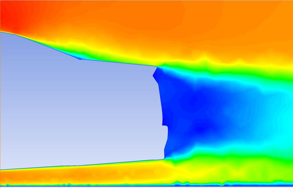
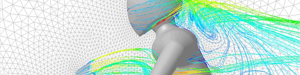
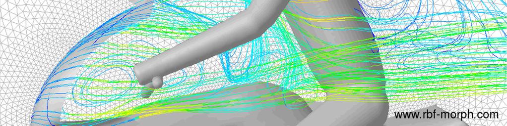
57 Motorbike driver height and position The original motorbike model is parameterized to investigate the effect of driver height and position: 1. Changing of driver height [-5 cm, 0 cm, 5 cm]; 2. Changing of driver position acting on the hunching angle [0,7.5,15 ]; 57


58 Set up of RBF Morph The morphed action is limited in the box region domain 1. The motion of the surfaces inside the encapsulation domain is imposed to the points on the windshield (fixed), the fairing (fixed) and the helmet (moving). Driver height is changed moving the helmet Driver position is changed rotating the helmet around the ankle 58


59 Motorbike Windshield (Bricomoto, MRA) 59

60 60 Formula 1 Front Wing


61 Sails Trim (Ignazio Maria Viola, University of Newcastle) 61


62 Generic Formula 1 Front End 62


63 Generic Formula 1 Front End 63

64 Fluid Structure Interaction 64

65 Turbine Blade 65

 66")
66 MIRA Reference car (MIRA ltd) 66
67 Conclusions A shape parametric CFD model can be defined using ANSYS Fluent and RBF Morph. Such parametric CFD model can be easily coupled with preferred optimization tools to steer the solution to an optimal design that can be imported in the preferred CAD platform (using STEP) Proposed approach dramatically reduces the man time required for set-up widening the CFD calculation capability M.E. Biancolini, Mesh morphing and smoothing by means of Radial Basis Functions (RBF): a practical example using Fluent and RBF Morph in Handbook of Research on Computational Science and Engineering: Theory and Practice ( 67


68 Using CFX moving mesh for optimisation The preceding mesh morphing sections have been on Fluent, but the moving mesh model in CFX can also be used as the basis of an optimisation Solid body motion and deflections can be applied and the mesh will morph to accommodate the movement Multiple scenarios can then be run with one mesh 68
69 Agenda Optimisation Tools for CFD Introduction Manual Optimisation and Scripting Design Xplorer(DX) Mesh Morpher or Shape Optimiser RBF-Morph AdjointSolver Remote Solve Manager (RSM) Summary 69

70 The Adjoint Solver The Adjointsolver is anadditional solver within Fluent that is run after the conventional solution is converged The Adjointsolver is used to assess the sensitivity of output parameters such as lift, drag or pressure drop to inputparameters such as the geometrical shape without the need for additional runs The output from the Adjoint solver is typically a surface vector field that illustrates how the geometry would need to change to increase or decrease the output parameter of interest Assuch it forms a very useful tool in an optimisation study and can be linked to the mesh morpher Drag sensitivity for NACA
71 Adjoint Solver Key Ideas - Fundamentals High-level system view of a conventional flow solver Inputs Boundary mesh Interior mesh Material properties Boundary condition 1 Flow angle Inlet velocity FLOW SOLVER Outputs Field data Contour plots Vector plots xy-plots Scalar values Lift Drag Total pressure drop 71
72 Adjoint Solver Fundamentals HOW ARE CHANGES TO KEY OUTPUTS DEPENDENT ON CHANGES TO THE INPUTS? Inputs Boundary mesh Interior mesh Material properties Boundary condition 1 Flow angle Inlet velocity? ADJOINT SOLVER Outputs Field data Contour plots Vector plots xy-plots Scalar values Lift Drag Total pressure drop 72
73 Adjoint Solver Key Ideas The Adjointsolver can be used to compute the derivative of a chosen observation of engineering interest with respect to all the input data for the system. Solving an adjointproblem is not trivial about as much effort as a flow solution. The adjointsolution provides guidance on the optimal adjustment that will improve a system s performance. An adjointsolution can be used to estimate the effect of a change prior to actually making the change. Shape sensitivity data can be combined with mesh morphing to guide smooth mesh deformations. An adjointsolution can be used as part of a gradient-based optimization algorithm. 73

74 Adjoint Solver Mesh Morphing Completing the design cycle Mesh Morphing Sensitivity of lift to surface shape Use Bernstein polynomial-based morphing scheme Adjoint to deformation operation Surface shape sensitivity becomes control point sensitivity Benefit of this approach is two-fold Smoothsthe surfacesensitivity field Provides a smooth interior mesh deformation Select portions of the geometry to be modified Flow 74

75 Adjoint Solver Mesh Morphing Constrained motion Some walls within the control volume may be constrained not to move. A minimal adjustment is made to the control-point sensitivity field so that deformation of the wall is eliminated. Cast as a least-squares problem. Actual change 3.1 P = Total improvement of 8% 75
76 Adjoint Solver Current Functionality ANSYS-Fluent flow solver has very broad scope Adjoint is configured to compute solutions based on some assumptions Steady, incompressible, laminar flow. Steady, incompressible, turbulent flow with standard wall functions. First-order discretization in space. Frozen turbulence. The primary flow solution does NOT need to be run with these restrictions Strong evidence that these assumptions do not undermine the utility of the adjoint solution data for engineering purposes. Fully parallelized. Gradient algorithm for shape modification Mesh morphing using control points. Adjoint-based solution adaption 76

77 Adjoint Solver Example Test Cases S809 HAWT Blade Objective Maximise Lift/Drag Ratio 77


78 Adjoint Solver Example Test Cases S809 HAWT Blade The best lift/drag ratio is observed when setting observable for lift, and using a scale factor of 2.5. The new shape provides about 30% more lift than the original geometry Highest lift/drag ratio achieved 78


![[Pa] 60 50 40 30 20 10](/docs-images/80/82240852/images/79-2.jpg "79 End design 0 0 10 20")
79 Adjoint Solver Example Test Cases Internal ducting U bend 100 Base design p tot [Pa] End design Run [-]


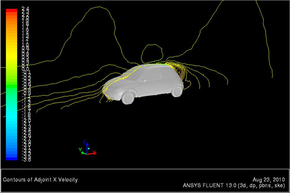
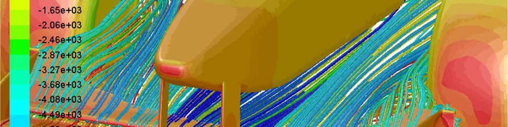
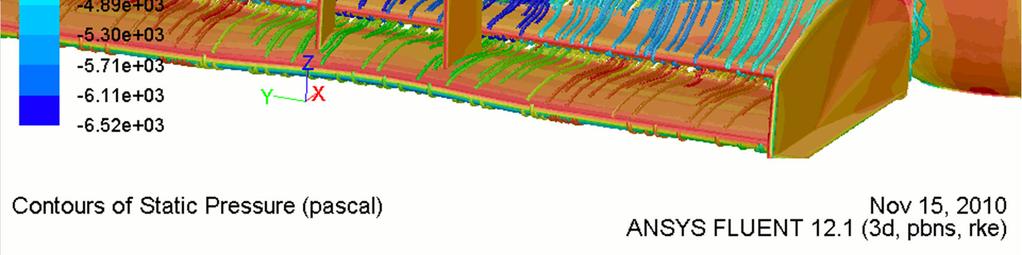
80 Adjoint Solver Example Test Cases External Aero (Small car) Surface map of the drag sensitivity to shape changes Surface map of the drag sensitivity to shape changes 80 Surface map of the drag sensitivity to shape changes

81 Adjoint Solver Example Test Cases External Aero (Full Generic Race Car) Increase the downforce on the vehicle Adjoint result shows regions of highest sensitivity of downforce to shape 81
 Front Wing changes Rear Wing Changes Downforce(N) Geometry")
 Geometry Predicted Result Original --- 425.")
82 Adjoint Solver Example Test Cases External Aero (Full Generic Race Car) Front Wing changes Rear Wing Changes Downforce(N) Geometry Predicted Result Original Modified Downforce(N) Geometry Predicted Result Original Modified
83 Adjoint Solver Summary The Adjoint solution is carried out as an addition to the primary flow solution The Adjointsolver solves the NavierStokes equations recast as derivatives of output flow variables of interest such as drag, lift or pressure drop As the equations are rewritten only a finite number of predefined flow variables of interest are available The output from the Adjointis a field of the sensitivity of inputs such as the geometry and boundary conditions to the output variables of interest. This can form the basis for optimising these inputs. 83
84 Agenda Optimisation Tools for CFD Introduction Manual Optimisation and Scripting Design Xplorer(DX) Mesh Morpher or Shape Optimiser RBF-Morph AdjointSolver Remote Solve Manager (RSM) Summary 84

85 The Remote Solve Manager (RSM) RSM has a three tiered architecture Client Solver Manager Compute Server 85


86 A queue can be set up on the solver manager for multiple compute cores which may be available on the network All design points are then submitted to this queue Design points are run as compute cores become available WB session can be detached and reattached Results picked up by WB when complete The Remote Solve Manager (RSM) 86


 level")

87 Workbench RSM Terminology There are RSM controls at both the solution level, e.g. FLUENT or CFX, to control how jobs are run, and also at the parameter set (global) level giving good control of resource utilisation Solution Component properties Parameter Set properties 87
88 RSM Summary Optimisation can create a large number of design points that would be slow to run sequentially in serial. In R14 the Remote Solve Manager provides a way of controlling compute resource allocation for CFD design point/ optimisation studies to allow multiple design points to be submitted to a queue of available compute nodes. 88
89 Agenda Optimisation Tools for CFD Introduction Manual Optimisation and Scripting Design Xplorer(DX) Mesh Morpher or Shape Optimiser RBF-Morph AdjointSolver Remote Solve Manager (RSM) Summary 89
90 Summary Where should I use these tools? Manual Optimisation and Scripting I want high level control on the meshes to be generated and I am prepared to script the process Design Xplorer My optimisation may include a wider process or workflow in Workbench with input and output parameters coming from multiple simulations, and/or I am working with parametric geometry. My design spacemayhavelocalminimathatiwish toavoid.ihave agood ideaofnatureandlimitsofthedesignspaceandwanttoenforcestrict control on any changes. MMO I am interested arbitrary shape optimisation where geometry parameterisation may limit finding a true optimum. Constraints and prescribed deformations are secondary concerns. No additional cost. Can interface with Workbench but scripts needed. 90
91 Where should I use these tools? RBF-Morph I want high level control on the morphed geometry shape, for example can do solid body transformations and modify geometry in a manner consistent with using parameterised geometry. Highly beneficial where remeshing a parametric geometry is costly. Morphed modifications can be fed back to CAD. Additional cost. Adjoint Solver Summary I am interested in finding where I could potentially modify my geometry to make small improvements. Which areas are most contributing to lift, drag, pressure drop Limitations on models and objective functions. No additional cost. No interaction with Workbench, solver only. Geometry deformation is free form as with the MMO. 91
92 Conclusions ANSYS can provide tools to drive your design to optimise for chosen parameters This can be done with geometric parameterisation, mesh replacement or morphing technologies Some tools can provide predicted off design performance without running multiple design points The Remote Solve Manager allows the efficient handling of large numbers of design points We are continually developing these new technologies to be more efficient We want to listen to your feedback to improve the usefulness of the tools Increase your ROI using the ANSYS optimisation tools 92
Shape optimisation using breakthrough technologies
 Shape optimisation using breakthrough technologies Compiled by Mike Slack Ansys Technical Services 2010 ANSYS, Inc. All rights reserved. 1 ANSYS, Inc. Proprietary Introduction Shape optimisation technologies
Mesh Morphing and the Adjoint Solver in ANSYS R14.0. Simon Pereira Laz Foley
 Mesh Morphing and the Adjoint Solver in ANSYS R14.0 Simon Pereira Laz Foley 1 Agenda Fluent Morphing-Optimization Feature RBF Morph with ANSYS DesignXplorer Adjoint Solver What does an adjoint solver do,
RBF Morph An Add-on Module for Mesh Morphing in ANSYS Fluent
 RBF Morph An Add-on Module for Mesh Morphing in ANSYS Fluent Gilles Eggenspieler Senior Product Manager 1 Morphing & Smoothing A mesh morpher is a tool capable of performing mesh modifications in order
An advanced RBF Morph application: coupled CFD-CSM Aeroelastic Analysis of a Full Aircraft Model and Comparison to Experimental Data
 An advanced RBF Morph application: coupled CFD-CSM Aeroelastic Analysis of a Full Aircraft Model and Comparison to Experimental Data Dr. Marco Evangelos Biancolini Tor Vergata University, Rome, Italy Dr.
Automated Design Exploration and Optimization. Clinton Smith, PhD CAE Support and Training PADT April 26, 2012
 Automated Design Exploration and Optimization Clinton Smith, PhD CAE Support and Training PADT April 26, 2012 1 Agenda The path to robust design A closer look at what DX offers Some examples 2 The Path
RBF Morph: mesh morphing in OpenFoam
 RBF Morph: mesh morphing in OpenFoam Dr. Marco Evangelos Biancolini University of Rome Tor Vergata @ CINECA, 26-28 March 2014 Cineca - BOLOGNA RBF Morph Training PRACE School 2013 Session #1 General Introduction
Adjoint Solver Workshop
 Adjoint Solver Workshop Why is an Adjoint Solver useful? Design and manufacture for better performance: e.g. airfoil, combustor, rotor blade, ducts, body shape, etc. by optimising a certain characteristic
Fluid structure interaction analysis: vortex shedding induced vibrations
 Fluid structure interaction analysis: vortex shedding induced vibrations N. Di Domenico, M. E. * University of Rome «Tor Vergata», Department of Enterprise Engineering «Mario Lucertini» A. Wade, T. Berg,
Automated Design Exploration and Optimization + HPC Best Practices
 Automated Design Exploration and Optimization + HPC Best Practices 1 Outline The Path to Robust Design ANSYS DesignXplorer Mesh Morphing and Optimizer RBF Morph Adjoint Solver HPC Best Practices 2 The
Introduction to ANSYS CFX
 Workshop 03 Fluid flow around the NACA0012 Airfoil 16.0 Release Introduction to ANSYS CFX 2015 ANSYS, Inc. March 13, 2015 1 Release 16.0 Workshop Description: The flow simulated is an external aerodynamics
Speed and Accuracy of CFD: Achieving Both Successfully ANSYS UK S.A.Silvester
 Speed and Accuracy of CFD: Achieving Both Successfully ANSYS UK S.A.Silvester 2010 ANSYS, Inc. All rights reserved. 1 ANSYS, Inc. Proprietary Content ANSYS CFD Introduction ANSYS, the company Simulation
Lecture 7: Mesh Quality & Advanced Topics. Introduction to ANSYS Meshing Release ANSYS, Inc. February 12, 2015
 Lecture 7: Mesh Quality & Advanced Topics 15.0 Release Introduction to ANSYS Meshing 1 2015 ANSYS, Inc. February 12, 2015 Overview In this lecture we will learn: Impact of the Mesh Quality on the Solution
Topology Optimization in Fluid Dynamics
 A Methodology for Topology Optimization in Fluid Dynamics 1 Chris Cowan Ozen Engineering, Inc. 1210 E. Arques Ave, Suite 207 Sunnyvale, CA 94085 info@ozeninc.com Ozen Engineering Inc. We are your local
Design Exploration and Robust Design. Judd Kaiser Product Manager, ANSYS Workbench Platform
 Design Exploration and Robust Design Judd Kaiser Product Manager, ANSYS Workbench Platform 1 Agenda 2 What is Robust Design? At ANSYS Workbench Principles DesignXplorer ANSYS Vision What is Robust Design?
ANSYS Fluid Structure Interaction for Thermal Management and Aeroelasticity
 ANSYS Fluid Structure Interaction for Thermal Management and Aeroelasticity Phil Stopford Duxford Air Museum 11th May 2011 2011 2010 ANSYS, Inc. All rights reserved. 1 ANSYS, Inc. Proprietary Fluid Structure
ANSYS FLUENT. Lecture 3. Basic Overview of Using the FLUENT User Interface L3-1. Customer Training Material
 Lecture 3 Basic Overview of Using the FLUENT User Interface Introduction to ANSYS FLUENT L3-1 Parallel Processing FLUENT can readily be run across many processors in parallel. This will greatly speed up
Introduction to CFX. Workshop 2. Transonic Flow Over a NACA 0012 Airfoil. WS2-1. ANSYS, Inc. Proprietary 2009 ANSYS, Inc. All rights reserved.
 Workshop 2 Transonic Flow Over a NACA 0012 Airfoil. Introduction to CFX WS2-1 Goals The purpose of this tutorial is to introduce the user to modelling flow in high speed external aerodynamic applications.
Aerodynamic Study of a Realistic Car W. TOUGERON
 Aerodynamic Study of a Realistic Car W. TOUGERON Tougeron CFD Engineer 2016 Abstract This document presents an aerodynamic CFD study of a realistic car geometry. The aim is to demonstrate the efficiency
Parametric. Practices. Patrick Cunningham. CAE Associates Inc. and ANSYS Inc. Proprietary 2012 CAE Associates Inc. and ANSYS Inc. All rights reserved.
 Parametric Modeling Best Practices Patrick Cunningham July, 2012 CAE Associates Inc. and ANSYS Inc. Proprietary 2012 CAE Associates Inc. and ANSYS Inc. All rights reserved. E-Learning Webinar Series This
Strategies to Achieve Reliable and Accurate CFD Solutions
 Strategies to Achieve Reliable and Accurate CFD Solutions Mark Keating ANSYS UK 2010 ANSYS, Inc. All rights reserved. 1 ANSYS, Inc. Proprietary Agenda Why develop a CFD strategy? Pre-Processing Strategies
Workshop 3: Cutcell Mesh Generation. Introduction to ANSYS Fluent Meshing Release. Release ANSYS, Inc.
 Workshop 3: Cutcell Mesh Generation 14.5 Release Introduction to ANSYS Fluent Meshing 1 2011 ANSYS, Inc. December 21, 2012 I Introduction Workshop Description: CutCell meshing is a general purpose meshing
State of the art at DLR in solving aerodynamic shape optimization problems using the discrete viscous adjoint method
 DLR - German Aerospace Center State of the art at DLR in solving aerodynamic shape optimization problems using the discrete viscous adjoint method J. Brezillon, C. Ilic, M. Abu-Zurayk, F. Ma, M. Widhalm
Ansys Fluent R Michele Andreoli
 Ansys Fluent R 17.0 Michele Andreoli (m.andreoli@enginsoft.it) Table of contents User Interface Fluent Meshing Solver Numerics New features Innovative Solutions New User Interface: Ribbon-Driven Solver
Shape Optimization for Aerodynamic Efficiency Using Adjoint Methods
 White Paper Shape Optimization for Aerodynamic Efficiency Using Adjoint Methods Adjoint solvers take a Computational Fluid Dynamics (CFD) flow solution and calculate the sensitivity of performance indicators
Accurate and Efficient Turbomachinery Simulation. Chad Custer, PhD Turbomachinery Technical Specialist
 Accurate and Efficient Turbomachinery Simulation Chad Custer, PhD Turbomachinery Technical Specialist Outline Turbomachinery simulation advantages Axial fan optimization Description of design objectives
Validation of an Unstructured Overset Mesh Method for CFD Analysis of Store Separation D. Snyder presented by R. Fitzsimmons
 Validation of an Unstructured Overset Mesh Method for CFD Analysis of Store Separation D. Snyder presented by R. Fitzsimmons Stores Separation Introduction Flight Test Expensive, high-risk, sometimes catastrophic
Fast Radial Basis Functions for Engineering Applications. Prof. Marco Evangelos Biancolini University of Rome Tor Vergata
 Fast Radial Basis Functions for Engineering Applications Prof. Marco Evangelos Biancolini University of Rome Tor Vergata Outline 2 RBF background Fast RBF on HPC Engineering Applications Mesh morphing
Overview and Recent Developments of Dynamic Mesh Capabilities
 Overview and Recent Developments of Dynamic Mesh Capabilities Henrik Rusche and Hrvoje Jasak h.rusche@wikki-gmbh.de and h.jasak@wikki.co.uk Wikki Gmbh, Germany Wikki Ltd, United Kingdom 6th OpenFOAM Workshop,
GEOMETRY MODELING & GRID GENERATION
 GEOMETRY MODELING & GRID GENERATION Dr.D.Prakash Senior Assistant Professor School of Mechanical Engineering SASTRA University, Thanjavur OBJECTIVE The objectives of this discussion are to relate experiences
Introduction to ANSYS DesignXplorer
 Overview 14. 5 Release Introduction to ANSYS DesignXplorer 1 2013 ANSYS, Inc. September 27, 2013 What is DesignXplorer? DesignXplorer (DX) is a tool that uses response surfaces and direct optimization
Solver Basics. Introductory FLUENT Training ANSYS, Inc. All rights reserved. ANSYS, Inc. Proprietary
 Solver Basics Introductory FLUENT Training 2006 ANSYS, Inc. All rights reserved. 2006 ANSYS, Inc. All rights reserved. 3-2 Solver Execution The menus are arranged such that the order of operation is generally
CFD Analysis of conceptual Aircraft body
 CFD Analysis of conceptual Aircraft body Manikantissar 1, Dr.Ankur geete 2 1 M. Tech scholar in Mechanical Engineering, SD Bansal college of technology, Indore, M.P, India 2 Associate professor in Mechanical
TAU mesh deformation. Thomas Gerhold
 TAU mesh deformation Thomas Gerhold The parallel mesh deformation of the DLR TAU-Code Introduction Mesh deformation method & Parallelization Results & Applications Conclusion & Outlook Introduction CFD
Open source software tools for powertrain optimisation
 Open source software tools for powertrain optimisation Paolo Geremia Eugene de Villiers TWO-DAY MEETING ON INTERNAL COMBUSTION ENGINE SIMULATIONS USING OPENFOAM TECHNOLOGY 11-12 July, 2011 info@engys.eu
Thank you for downloading one of our ANSYS whitepapers we hope you enjoy it.
 Thank you! Thank you for downloading one of our ANSYS whitepapers we hope you enjoy it. Have questions? Need more information? Please don t hesitate to contact us! We have plenty more where this came from.
Adjoint Solver Advances, Tailored to Automotive Applications
 Adjoint Solver Advances, Tailored to Automotive Applications Stamatina Petropoulou s.petropoulou@iconcfd.com 1 Contents 1. Icon s Principal Work in FlowHead 2. Demonstration Cases 3. Icon s Further Development
Introduction to C omputational F luid Dynamics. D. Murrin
 Introduction to C omputational F luid Dynamics D. Murrin Computational fluid dynamics (CFD) is the science of predicting fluid flow, heat transfer, mass transfer, chemical reactions, and related phenomena
Using a Single Rotating Reference Frame
 Tutorial 9. Using a Single Rotating Reference Frame Introduction This tutorial considers the flow within a 2D, axisymmetric, co-rotating disk cavity system. Understanding the behavior of such flows is
Free-Form Shape Optimization using CAD Models
 Free-Form Shape Optimization using CAD Models D. Baumgärtner 1, M. Breitenberger 1, K.-U. Bletzinger 1 1 Lehrstuhl für Statik, Technische Universität München (TUM), Arcisstraße 21, D-80333 München 1 Motivation
Studies of the Continuous and Discrete Adjoint Approaches to Viscous Automatic Aerodynamic Shape Optimization
 Studies of the Continuous and Discrete Adjoint Approaches to Viscous Automatic Aerodynamic Shape Optimization Siva Nadarajah Antony Jameson Stanford University 15th AIAA Computational Fluid Dynamics Conference
Auto Injector Syringe. A Fluent Dynamic Mesh 1DOF Tutorial
 Auto Injector Syringe A Fluent Dynamic Mesh 1DOF Tutorial 1 2015 ANSYS, Inc. June 26, 2015 Prerequisites This tutorial is written with the assumption that You have attended the Introduction to ANSYS Fluent
CFD MODELING FOR PNEUMATIC CONVEYING
 CFD MODELING FOR PNEUMATIC CONVEYING Arvind Kumar 1, D.R. Kaushal 2, Navneet Kumar 3 1 Associate Professor YMCAUST, Faridabad 2 Associate Professor, IIT, Delhi 3 Research Scholar IIT, Delhi e-mail: arvindeem@yahoo.co.in
CFD Optimisation case studies with STAR-CD and STAR-CCM+
 CFD Optimisation case studies with STAR-CD and STAR-CCM+ Summary David J. Eby, Preetham Rao, Advanced Methods Group, Plymouth, MI USA Presented by Fred Mendonça, CD-adapco London, UK Outline Introduction
MATH 573 Advanced Scientific Computing
 MATH 573 Advanced Scientific Computing Analysis of an Airfoil using Cubic Splines Ashley Wood Brian Song Ravindra Asitha What is Airfoil? - The cross-section of the wing, blade, or sail. 1. Thrust 2. Weight
Verification and Validation of Turbulent Flow around a Clark-Y Airfoil
 1 Verification and Validation of Turbulent Flow around a Clark-Y Airfoil 1. Purpose ME:5160 Intermediate Mechanics of Fluids CFD LAB 2 (ANSYS 19.1; Last Updated: Aug. 7, 2018) By Timur Dogan, Michael Conger,
Estimation of Flow Field & Drag for Aerofoil Wing
 Estimation of Flow Field & Drag for Aerofoil Wing Mahantesh. HM 1, Prof. Anand. SN 2 P.G. Student, Dept. of Mechanical Engineering, East Point College of Engineering, Bangalore, Karnataka, India 1 Associate
Using Multiple Rotating Reference Frames
 Tutorial 10. Using Multiple Rotating Reference Frames Introduction Many engineering problems involve rotating flow domains. One example is the centrifugal blower unit that is typically used in automotive
Commercial Implementations of Optimization Software and its Application to Fluid Dynamics Problems
 Commercial Implementations of Optimization Software and its Application to Fluid Dynamics Problems Szymon Buhajczuk, M.A.Sc SimuTech Group Toronto Fields Institute Optimization Seminar December 6, 2011
ANSYS FLUENT. Airfoil Analysis and Tutorial
 ANSYS FLUENT Airfoil Analysis and Tutorial ENGR083: Fluid Mechanics II Terry Yu 5/11/2017 Abstract The NACA 0012 airfoil was one of the earliest airfoils created. Its mathematically simple shape and age
Automatic & Robust Meshing in Fluids 2011 ANSYS Regional Conferences
 Automatic & Robust Meshing in Fluids 2011 ANSYS Regional Conferences 1 This is just a taste Note that full 14.0 update webinars of an hour per product will be scheduled closer to the release This presentation
Simulating Sinkage & Trim for Planing Boat Hulls. A Fluent Dynamic Mesh 6DOF Tutorial
 Simulating Sinkage & Trim for Planing Boat Hulls A Fluent Dynamic Mesh 6DOF Tutorial 1 Introduction Workshop Description This workshop describes how to perform a transient 2DOF simulation of a planing
Influence of mesh quality and density on numerical calculation of heat exchanger with undulation in herringbone pattern
 Influence of mesh quality and density on numerical calculation of heat exchanger with undulation in herringbone pattern Václav Dvořák, Jan Novosád Abstract Research of devices for heat recovery is currently
Transition Flow and Aeroacoustic Analysis of NACA0018 Satish Kumar B, Fred Mendonç a, Ghuiyeon Kim, Hogeon Kim
 Transition Flow and Aeroacoustic Analysis of NACA0018 Satish Kumar B, Fred Mendonç a, Ghuiyeon Kim, Hogeon Kim Transition Flow and Aeroacoustic Analysis of NACA0018 Satish Kumar B, Fred Mendonç a, Ghuiyeon
CFD-1. Introduction: What is CFD? T. J. Craft. Msc CFD-1. CFD: Computational Fluid Dynamics
 School of Mechanical Aerospace and Civil Engineering CFD-1 T. J. Craft George Begg Building, C41 Msc CFD-1 Reading: J. Ferziger, M. Peric, Computational Methods for Fluid Dynamics H.K. Versteeg, W. Malalasekara,
Introduction to ANSYS DesignXplorer
 Lecture 4 14. 5 Release Introduction to ANSYS DesignXplorer 1 2013 ANSYS, Inc. September 27, 2013 s are functions of different nature where the output parameters are described in terms of the input parameters
New Technologies in CST STUDIO SUITE CST COMPUTER SIMULATION TECHNOLOGY
 New Technologies in CST STUDIO SUITE 2016 Outline Design Tools & Modeling Antenna Magus Filter Designer 2D/3D Modeling 3D EM Solver Technology Cable / Circuit / PCB Systems Multiphysics CST Design Tools
THE BENEFIT OF ANSA TOOLS IN THE DALLARA CFD PROCESS. Simona Invernizzi, Dallara Engineering, Italy,
 THE BENEFIT OF ANSA TOOLS IN THE DALLARA CFD PROCESS Simona Invernizzi, Dallara Engineering, Italy, KEYWORDS automatic tools, batch mesh, DFM, morphing, ride height maps ABSTRACT In the last few years,
Analysis of an airfoil
 UNDERGRADUATE RESEARCH FALL 2010 Analysis of an airfoil using Computational Fluid Dynamics Tanveer Chandok 12/17/2010 Independent research thesis at the Georgia Institute of Technology under the supervision
Workbench Tutorial Flow Over an Airfoil, Page 1 ANSYS Workbench Tutorial Flow Over an Airfoil
 Workbench Tutorial Flow Over an Airfoil, Page 1 ANSYS Workbench Tutorial Flow Over an Airfoil Authors: Scott Richards, Keith Martin, and John M. Cimbala, Penn State University Latest revision: 17 January
Introduction to ANSYS FLUENT Meshing
 Workshop 02 Volume Fill Methods Introduction to ANSYS FLUENT Meshing 1 2011 ANSYS, Inc. December 21, 2012 I Introduction Workshop Description: Mesh files will be read into the Fluent Meshing software ready
ANSYS AIM 16.0 Overview. AIM Program Management
 1 2015 ANSYS, Inc. September 27, 2015 ANSYS AIM 16.0 Overview AIM Program Management 2 2015 ANSYS, Inc. September 27, 2015 Today s Simulation Challenges Leveraging simulation across engineering organizations
Calculate a solution using the pressure-based coupled solver.
 Tutorial 19. Modeling Cavitation Introduction This tutorial examines the pressure-driven cavitating flow of water through a sharpedged orifice. This is a typical configuration in fuel injectors, and brings
Tutorial 1. Introduction to Using FLUENT: Fluid Flow and Heat Transfer in a Mixing Elbow
 Tutorial 1. Introduction to Using FLUENT: Fluid Flow and Heat Transfer in a Mixing Elbow Introduction This tutorial illustrates the setup and solution of the two-dimensional turbulent fluid flow and heat
An advanced RBF Morph application: coupled CFD-CSM Aeroelastic Analysis of a Full Aircraft Model and Comparison to Experimental Data
 An advanced RBF Morph application: coupled CFD-CSM Aeroelastic Analysis of a Full Aircraft Model and Comparison to Experimental Data Ubaldo Cella 1 Piaggio Aero Industries, Naples, Italy Marco Evangelos
Multi-objective adjoint optimization of flow in duct and pipe networks
 Multi-objective adjoint optimization of flow in duct and pipe networks Eugene de Villiers Thomas Schumacher 6th OPENFOAM Workshop PennState University, USA 13-16 June, 2011 info@engys.eu Tel: +44 (0)20
COMPUTATIONAL FLUID DYNAMICS ANALYSIS OF ORIFICE PLATE METERING SITUATIONS UNDER ABNORMAL CONFIGURATIONS
 COMPUTATIONAL FLUID DYNAMICS ANALYSIS OF ORIFICE PLATE METERING SITUATIONS UNDER ABNORMAL CONFIGURATIONS Dr W. Malalasekera Version 3.0 August 2013 1 COMPUTATIONAL FLUID DYNAMICS ANALYSIS OF ORIFICE PLATE
KEYWORDS Morphing, CAE workflow, Optimization, Automation, DOE, Regression, CFD, FEM, Python
 DESIGN OPTIMIZATION WITH ANSA MORPH 1 Tobias Eidevåg *, 1 David Tarazona Ramos *, 1 Mohammad El-Alti 1 Alten AB, Sweden KEYWORDS Morphing, CAE workflow, Optimization, Automation, DOE, Regression, CFD,
NUMERICAL 3D TRANSONIC FLOW SIMULATION OVER A WING
 Review of the Air Force Academy No.3 (35)/2017 NUMERICAL 3D TRANSONIC FLOW SIMULATION OVER A WING Cvetelina VELKOVA Department of Technical Mechanics, Naval Academy Nikola Vaptsarov,Varna, Bulgaria (cvetelina.velkova1985@gmail.com)
Recent & Upcoming Features in STAR-CCM+ for Aerospace Applications Deryl Snyder, Ph.D.
 Recent & Upcoming Features in STAR-CCM+ for Aerospace Applications Deryl Snyder, Ph.D. Outline Introduction Aerospace Applications Summary New Capabilities for Aerospace Continuity Convergence Accelerator
Computational Simulation of the Wind-force on Metal Meshes
 16 th Australasian Fluid Mechanics Conference Crown Plaza, Gold Coast, Australia 2-7 December 2007 Computational Simulation of the Wind-force on Metal Meshes Ahmad Sharifian & David R. Buttsworth Faculty
The Spalart Allmaras turbulence model
 The Spalart Allmaras turbulence model The main equation The Spallart Allmaras turbulence model is a one equation model designed especially for aerospace applications; it solves a modelled transport equation
Missile External Aerodynamics Using Star-CCM+ Star European Conference 03/22-23/2011
 Missile External Aerodynamics Using Star-CCM+ Star European Conference 03/22-23/2011 StarCCM_StarEurope_2011 4/6/11 1 Overview 2 Role of CFD in Aerodynamic Analyses Classical aerodynamics / Semi-Empirical
Adjoint Optimization combined with mesh morphing for CFD applications
 Adjoint Optimization combined with mesh morphing for CFD applications Alberto Clarich*, Luca Battaglia*, Enrico Nobile**, Marco Evangelos Biancolini, Ubaldo Cella *ESTECO Spa, Italy. Email: engineering@esteco.com
Verification of Laminar and Validation of Turbulent Pipe Flows
 1 Verification of Laminar and Validation of Turbulent Pipe Flows 1. Purpose ME:5160 Intermediate Mechanics of Fluids CFD LAB 1 (ANSYS 18.1; Last Updated: Aug. 1, 2017) By Timur Dogan, Michael Conger, Dong-Hwan
OzenCloud Case Studies
 OzenCloud Case Studies Case Studies, April 20, 2015 ANSYS in the Cloud Case Studies: Aerodynamics & fluttering study on an aircraft wing using fluid structure interaction 1 Powered by UberCloud http://www.theubercloud.com
CFD Topological Optimization of a Car Water-Pump Inlet using TOSCA Fluid and STAR- CCM+
 CFD Topological Optimization of a Car Water-Pump Inlet using TOSCA Fluid and STAR- CCM+ Dr. Anselm Hopf Dr. Andrew Hitchings Les Routledge Ford Motor Company CONTENTS Introduction/Motivation Optimization
Application of Wray-Agarwal Turbulence Model for Accurate Numerical Simulation of Flow Past a Three-Dimensional Wing-body
 Washington University in St. Louis Washington University Open Scholarship Mechanical Engineering and Materials Science Independent Study Mechanical Engineering & Materials Science 4-28-2016 Application
Flow and Heat Transfer in a Mixing Elbow
 Flow and Heat Transfer in a Mixing Elbow Objectives The main objectives of the project are to learn (i) how to set up and perform flow simulations with heat transfer and mixing, (ii) post-processing and
A NURBS-BASED APPROACH FOR SHAPE AND TOPOLOGY OPTIMIZATION OF FLOW DOMAINS
 6th European Conference on Computational Mechanics (ECCM 6) 7th European Conference on Computational Fluid Dynamics (ECFD 7) 11 15 June 2018, Glasgow, UK A NURBS-BASED APPROACH FOR SHAPE AND TOPOLOGY OPTIMIZATION
Webinar: TwinMesh for Reliable CFD Analysis of Rotating Positive Displacement Machines
 Webinar: TwinMesh for Reliable CFD Analysis of Rotating Positive Displacement Machines 14.07.2015 Dipl.-Ing. Jan Hesse Jan.hesse@cfx-berlin.de CFX Berlin Software GmbH Karl-Marx-Allee 90 A 10243 Berlin
FFD, mesh morphing & reduced order models: Enablers for efficient aerodynamic shape optimization
 FFD, mesh morphing & reduced order models: Enablers for efficient aerodynamic shape optimization F Salmoiraghi, G Rozza SISSA mathlab A Scardigli, H Telib OPTIMAD engineering srl Outline 1. Prac'cal)problems)in)shape)op'miza'on)
Composite Optimisation of an F1 Front Wing
 Composite Optimisation of an F1 Front Wing Jonathan Heal Senior Stress Engineer, McLaren Racing Ltd McLaren Technology Centre, Chertsey Rd, Woking. GU21 4YH Jonathan.heal@mclaren.com Abstract Formula one
µ = Pa s m 3 The Reynolds number based on hydraulic diameter, D h = 2W h/(w + h) = 3.2 mm for the main inlet duct is = 359
 = 3.2 mm for the main inlet duct is = 359") Laminar Mixer Tutorial for STAR-CCM+ ME 448/548 March 30, 2014 Gerald Recktenwald gerry@pdx.edu 1 Overview Imagine that you are part of a team developing a medical diagnostic device. The device has a millimeter
Laminar Mixer Tutorial for STAR-CCM+ ME 448/548 March 30, 2014 Gerald Recktenwald gerry@pdx.edu 1 Overview Imagine that you are part of a team developing a medical diagnostic device. The device has a millimeter
Using Multiple Rotating Reference Frames
 Tutorial 9. Using Multiple Rotating Reference Frames Introduction Many engineering problems involve rotating flow domains. One example is the centrifugal blower unit that is typically used in automotive
Express Introductory Training in ANSYS Fluent Workshop 04 Fluid Flow Around the NACA0012 Airfoil
 Express Introductory Training in ANSYS Fluent Workshop 04 Fluid Flow Around the NACA0012 Airfoil Dimitrios Sofialidis Technical Manager, SimTec Ltd. Mechanical Engineer, PhD PRACE Autumn School 2013 -
Simulation of Turbulent Flow around an Airfoil
 1. Purpose Simulation of Turbulent Flow around an Airfoil ENGR:2510 Mechanics of Fluids and Transfer Processes CFD Lab 2 (ANSYS 17.1; Last Updated: Nov. 7, 2016) By Timur Dogan, Michael Conger, Andrew
Coupled Analysis of FSI
 Coupled Analysis of FSI Qin Yin Fan Oct. 11, 2008 Important Key Words Fluid Structure Interface = FSI Computational Fluid Dynamics = CFD Pressure Displacement Analysis = PDA Thermal Stress Analysis = TSA
Targeting Composite Wing Performance Optimising the Composite Lay-Up Design
 Targeting Composite Wing Performance Optimising the Composite Lay-Up Design Sam Patten Optimisation Specialist, Altair Engineering Ltd Imperial House, Holly Walk, Royal Leamington Spa, CV32 4JG sam.patten@uk.altair.com
Simulation of In-Cylinder Flow Phenomena with ANSYS Piston Grid An Improved Meshing and Simulation Approach
 Simulation of In-Cylinder Flow Phenomena with ANSYS Piston Grid An Improved Meshing and Simulation Approach Dipl.-Ing. (FH) Günther Lang, CFDnetwork Engineering Dipl.-Ing. Burkhard Lewerich, CFDnetwork
NUMERICAL INVESTIGATION OF THE FLOW BEHAVIOR INTO THE INLET GUIDE VANE SYSTEM (IGV)
") University of West Bohemia» Department of Power System Engineering NUMERICAL INVESTIGATION OF THE FLOW BEHAVIOR INTO THE INLET GUIDE VANE SYSTEM (IGV) Publication was supported by project: Budování excelentního
University of West Bohemia» Department of Power System Engineering NUMERICAL INVESTIGATION OF THE FLOW BEHAVIOR INTO THE INLET GUIDE VANE SYSTEM (IGV) Publication was supported by project: Budování excelentního
Automatic & Robust Meshing in Fluids 2011 ANSYS Regional Conferences
 Automatic & Robust Meshing in Fluids 2011 ANSYS Regional Conferences 1 Automatic & Robust Meshing Assembly Meshing Assembly Meshing enables dramatically reduced time to mesh for typical CAD models by eliminating
LS-DYNA 980 : Recent Developments, Application Areas and Validation Process of the Incompressible fluid solver (ICFD) in LS-DYNA.
 in LS-DYNA.") 12 th International LS-DYNA Users Conference FSI/ALE(1) LS-DYNA 980 : Recent Developments, Application Areas and Validation Process of the Incompressible fluid solver (ICFD) in LS-DYNA Part 1 Facundo Del
12 th International LS-DYNA Users Conference FSI/ALE(1) LS-DYNA 980 : Recent Developments, Application Areas and Validation Process of the Incompressible fluid solver (ICFD) in LS-DYNA Part 1 Facundo Del
I. Introduction. Optimization Algorithm Components. Abstract for the 5 th OpenFOAM User Conference 2017, Wiesbaden - Germany
 An Aerodynamic Optimization Framework for the Automotive Industry, based on Continuous Adjoint and OpenFOAM E. Papoutsis-Kiachagias 1, V. Asouti 1, K. Giannakoglou 1, K. Gkagkas 2 1) National Technical
Advances in Turbomachinery Simulation Fred Mendonça and material prepared by Chad Custer, Turbomachinery Technology Specialist
 Advances in Turbomachinery Simulation Fred Mendonça and material prepared by Chad Custer, Turbomachinery Technology Specialist Usage From Across the Industry Outline Key Application Objectives Conjugate
CFD VALIDATION FOR SURFACE COMBATANT 5415 STRAIGHT AHEAD AND STATIC DRIFT 20 DEGREE CONDITIONS USING STAR CCM+
 CFD VALIDATION FOR SURFACE COMBATANT 5415 STRAIGHT AHEAD AND STATIC DRIFT 20 DEGREE CONDITIONS USING STAR CCM+ by G. J. Grigoropoulos and I..S. Kefallinou 1. Introduction and setup 1. 1 Introduction The
Tutorial: Simulating a 3D Check Valve Using Dynamic Mesh 6DOF Model And Diffusion Smoothing
 Tutorial: Simulating a 3D Check Valve Using Dynamic Mesh 6DOF Model And Diffusion Smoothing Introduction The purpose of this tutorial is to demonstrate how to simulate a ball check valve with small displacement
Revised Sheet Metal Simulation, J.E. Akin, Rice University
 Revised Sheet Metal Simulation, J.E. Akin, Rice University A SolidWorks simulation tutorial is just intended to illustrate where to find various icons that you would need in a real engineering analysis.
Composites for JEC Conference. Zach Abraham ANSYS, Inc.
 Composites for JEC Conference Zach Abraham ANSYS, Inc. 1 Our Strategy Simulation-Driven Product Development Fluid Dynamics Structural Mechanics Explicit Dynamics Low-Frequency Electromagnetics High-Frequency
2008 International ANSYS Conference Strongly Coupled FSI Simulation Moving Compressible Pressure Pulse through a Tube
 2008 International ANSYS Conference Strongly Coupled FSI Simulation Moving Compressible Pressure Pulse through a Tube Daniel L. Cler, US Army RDECOM/ ARDEC/ WSEC/ Benet Labs 1 Overview Background Problem
Verification and Validation of Turbulent Flow around a Clark-Y Airfoil
 Verification and Validation of Turbulent Flow around a Clark-Y Airfoil 1. Purpose 58:160 Intermediate Mechanics of Fluids CFD LAB 2 By Tao Xing and Fred Stern IIHR-Hydroscience & Engineering The University