Automated Design Exploration and Optimization + HPC Best Practices
|
|
|
- Maria Hood
- 6 years ago
- Views:
Transcription

1 Automated Design Exploration and Optimization + HPC Best Practices 1
2 Outline The Path to Robust Design ANSYS DesignXplorer Mesh Morphing and Optimizer RBF Morph Adjoint Solver HPC Best Practices 2


3 The Path to Robust Design Robust Design is an ANSYS Advantage Single Physics Solution Accuracy, robustness, speed Multiphysics Solution Integration Platform What if Study Parametric Platform Design Exploration DOE, Response Surfaces, Correlation, Sensitivity, Unified reporting, etc. Optimization Algorithms Published API Robust Design Six Sigma Analysis Probabilistic Algorithms Adjoint solver methods 3


4 What If? Interactively adjust the parameter values and Update Needed for "What If?" Parametric CAD Connections Pervasive Parameters Persistent Updates Managed State, Update Mechanisms Remote Solve Manager (RSM) Parametric Persistence is an ANSYS Advantage! 4
5 Design Exploration Design Exploration is an ANSYS Advantage 5

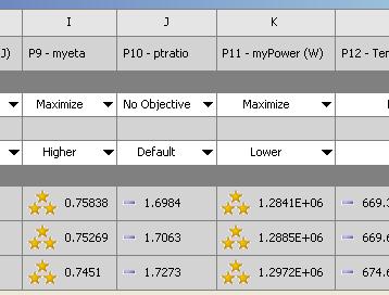
6 Optimization Optimal Candidates 6


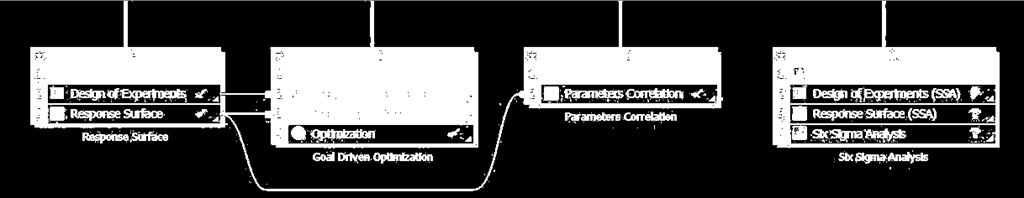
7 Six Sigma Analysis Thermal Stress Pressure & Flow Velocity Exhaust manifold design Six Sigma Analysis Input Parameters Outlet Diameter of the manifold Thickness at inlet External Temperature Engine RPM Parametric Geometry Maximum Displacement should not exceed 1.5 mm Response Parameters Max Flow Temperature Max Deformation Max Von-Mises stress Deformation All samples reports max deformation below 1.5 mm Uncertainty of input parameters Response Surface showing the effect of engine speed and thickness at outlet on the maximum deformation 7
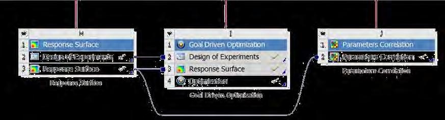
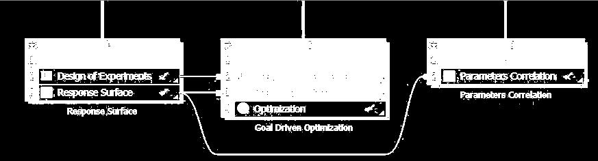
8 ANSYS DesignXplorer 9
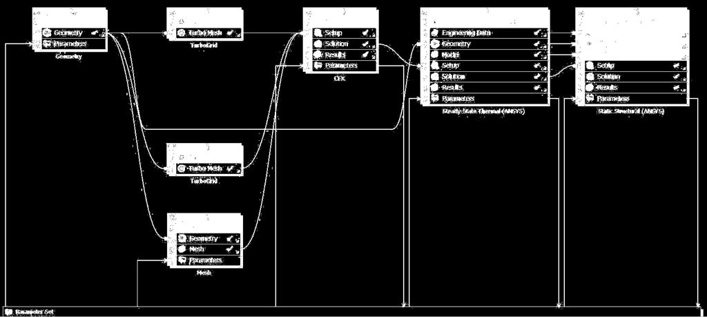
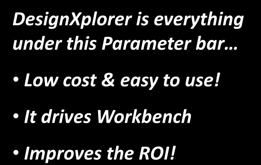


9 ANSYS DesignXplorer DesignXplorer is everything under this Parameter bar Low cost & easy to use! It drives Workbench Improves the ROI! ANSYS Workbench Solvers DX 10


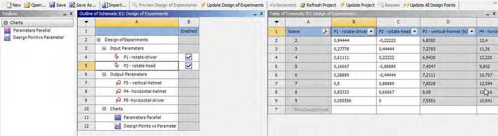
10 Design of Experiments With little more effort than for a single run, you can use DesignXplorer to create a DOE and run many variations. 11
11 Correlation Matrix Understand how your parameters are correlated/influenced by other parameters! 12


12 Sensitivity Understand which parameters your design is most sensitive to! 13


13 Response Surface Understand the sensitivities of the output parameters (results) wrt the input parameters. 3D Response 2D Slices Response 14


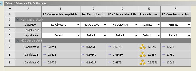
14 Goal-Driven Optimization Use an optimization algorithm or screening to understand tradeoffs or discover optimal design candidates! 15


15 Robustness Evaluation Input parameters have variation! Make sure your design is robust! Six Sigma, TQM Output parameters vary also! 16 Understand how your performance will vary with your design tolerances? Predict how many parts will likely fail? Understand which inputs require the greatest control?


16 Example 1: Slit Die Need uniform outflow Minimize pressure drop P2 P3 P1 Flow Uniformity BAD Bad GOOD Good Pressure Drop 17


17 Example 2: Combustor 3 parameters Diffuser Length Exit Height Outlet Minimize pressure loss Outlet Minimize mach number Outlet Inlet Dump Gap Sensitivity 18
18 Mesh Morphing and Optimizer 19
19 Fluent Morpher-Optimization Feature Allows users to optimize product design based on shape deformation to achieve design objective Based on free-form deformation tool coupled with various optimization methods 20


20 Mesh Morphing Applies a geometric design change directly to the mesh in the solver Uses a Bernstein polynomial-based morphing scheme Freeform mesh deformation defined on a matrix of control points leads to a smooth deformation Works on all mesh types (Tet/Prism, CutCell, HexaCore, Polyhedral) User prescribes the scale and direction of deformations to control points distributed evenly through the rectilinear region. 21


21 Process What if? Setup Case Run Setup Morph Morph Evaluate OR Regions Parameters Deformation Optimizer Optimizer Setup Case Run Setup Optimizer Optimize Auto 22 Choose best design Optimal Solution

 Select control")

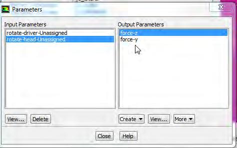
22 Deformation Definition Define constraint(s) (if any) Select control points and prescribe the relative ranges of motion 23


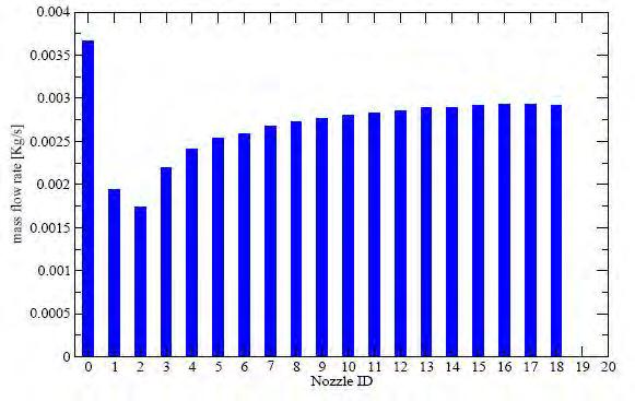
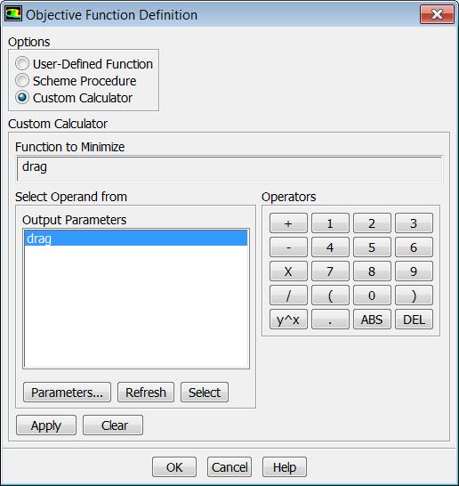
23 Objective Function Objective Function: Equal flow rate Baseline Design Optimized Design 24
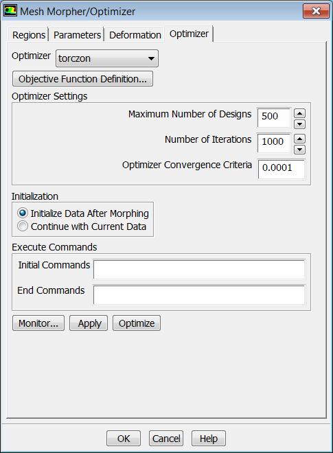


24 Optimizer Algorithms; Compass, Powell, Rosenbrock, Simplex, Torczon Auto Optimize! 25
25 Example: L-Shaped Duct Application: L-shaped duct Objective Function: Uniform flow at the outlet Significant Improvement in Flow Uniformity 26
26 RBF Morph 27
 in a short time Management of every kind of mesh element type (tetrahedral, hexahedral,")
27 RBF Morph Features The user-friendly RBF Morph add-on module is fully integrated within Fluent (GUI, TUI & solving stage) and Workbench Mesh-independent RBF fit used for surface mesh morphing and volume mesh smoothing Parallel calculation allows to morph large size models (many millions of cells) in a short time Management of every kind of mesh element type (tetrahedral, hexahedral, polyhedral, etc.) Ability to convert morphed mesh surfaces back into CAD Multi fit makes the Fluent case truly parametric (only 1 mesh is stored) Precision: exact nodal movement and exact feature preservation. 28

28 How Does RBF-Morph work? A system of radial functions is used to fit a solution for the mesh movement/morphing, from a list of source points and their prescribed displacements Radial Basis Function interpolation is used to derive the displacement at any location in the space The RBF problem definition is mesh independent. 29


29 RBF-Morph is Integrated with Fluent 30


30 Example 1: Internal Flow Here, a pipe is projected onto a previously defined STL shape 31

31 Example 2: External Flow courtesy of Ignazio Maria Viola Ship sail rotation 32


32 Example 3: External Flow 33


33 Example 4: 50:50:50 Optimisation Courtesy of Volvo Cars Recently conducted conceptual study by ANSYS in conjunction with Volvo Cars 50 Million cell hybrid mesh of Volvo XC60 50 Design variants investigated using RBF-Morph Addon for ANSYS Fluent and Workbench Design Explorer 50 hours total clock time to complete full optimisation on HPC Cluster ~4% Reduction in total drag force 34


34 Example 5: Ship Hull Optimisation Courtesy of Leeds University Ship hull hydrodynamics optimisation study Block hexahedral mesh from ICEM CFD 50 Design variants investigated using RBF-Morph Addon for ANSYS Fluent and Workbench Design Explorer 7.9% Reduction in total drag force 35
35 Adjoint Solver 36
36 Adjoint Solution? An adjoint solver allows specific information about a fluid system to be computed that is very difficult to gather otherwise. The adjoint solution itself is a set of derivatives. They are not particularly useful in their raw form and must be post-processed appropriately. The derivative of an engineering quantity with respect to all of the inputs for the system can be computed in a single calculation. Example: Sensitivity of the drag on an airfoil to its shape. There are 4 main ways in which these derivatives can be used: 1. Qualitative guidance on what can influence the performance of a system strongly. 2. Quantitative guidance on the anticipated effect of specific design changes. 3. Guidance on important factors in solver numerics. 4. Gradient-based design optimization. 37

37 How to Use the Results - Qualitative GOAL: Identify features of a system design that are most influential in the performance of the system. EXAMPLE: Sensitivity of the Drag on a NACA 0012 airfoil to changes in the shape of the airfoil. The shape sensitivity field is extracted from the adjoint solution in a post-processing step. High sensitivity changes to shape have a big effect on drag Low sensitivity changes to shape have a small effect on drag 38

38 How to Use the Results - Quantitative GOAL: Identify specific system design changes that benefit the performance and quantify the improvement in performance that is anticipated. EXAMPLE: Design modifications to turning vanes in a 90 degree elbow to reduce the total pressure drop. The optimal adjustment that is made to the shape is defined by the shape sensitivity field (steepest descent algorithm). Effect of each change can be computed in advance based on linear extrapolation. Baseline Modified Original P = Pa Expected change computed using the adjoint and linear extrapolation = 10.0 Pa Make the change and recompute the solution. Actual change = 9.0 Pa 39


39 How to Use the Results - Solver Numerics GOAL: Identify aspects of the solver numerics and computational mesh that have a strong influence on quantities that are being computed that are of engineering interest. EXAMPLE: Use the adjoint solution to identify parts of the mesh where mesh adaption will benefit the computed drag by reducing the influence of discretization errors. Baseline Mesh Adapted Mesh Adapted Mesh Detail 40


40 How to Use the Results - Optimization GOAL: Perform a sequence of automated design modifications to improve a specific performance measure for a system EXAMPLE: Gradient-based optimization of the total pressure drop in a pipe. Flow solution is recomputed and the adjoint recomputed at each design iteration Initial design p tot [Pa] Final design 30% reduction in total pressure drop after 30 design iterations Iteration


41 Mesh Morphing Once a desired change to the geometry of the system has been selected, how is that change to be made? Mesh morphing provides a convenient and powerful means of changing the geometry and the computational mesh. Use Bernstein polynomial-based morphing scheme discussed earlier 42
 Benefit of this approach is two-fold Smooths the surface sensitivity field Provides a smooth interior and boundary mesh deformation 43")
42 Mesh Morphing & Adjoint Data Example: Sensitivity of lift to surface shape Flow Select portions of the geometry to be modified Adjoint to deformation operation Surface shape sensitivity becomes control point sensitivity (chain rule for differentiation) Benefit of this approach is two-fold Smooths the surface sensitivity field Provides a smooth interior and boundary mesh deformation 43
43 Mesh Morphing, Adjoint Data & Constraints The adjoint solution is determined based on the specific flow physics of the problem in hand. The effect of other practical engineering constraints must be reconciled with the adjoint data to decide on an allowable design change. Example: Some walls within the control volume may be constrained not to move. A minimal adjustment is made to the control-point sensitivity field so that deformation of the fixed walls is eliminated. Fixed wall Fixed wall Moveable walls 44
44 Current Functionality The adjoint solver is released with all Fluent 14 packages. Documentation is available Theory Usage Tutorial Case study Training is available Functionality is activated by Loading the adjoint solver add-on module A new menu item is added at the top level 45
 Production automobiles (decrease drag) Low-speed internal flows Total pressure drop")

45 Current Functionality Application Drivers Key initial application areas are: Low-speed external aerodynamics F1 (increase downforce) Production automobiles (decrease drag) Low-speed internal flows Total pressure drop (reduce losses) In Fluent 14.5 a mechanism for users to define a wide range of observables of interest will be provided. Forces Moments Pressure drop Swirl Ratios Products Variances Linear combinations Unary operations 46
46 Current Scope ANSYS-Fluent flow solver has very broad scope Adjoint is configured to compute solutions based on some assumptions Steady, incompressible, laminar flow. Steady, incompressible, turbulent flow with standard wall functions. First-order discretization in space. Frozen turbulence. The primary flow solution does NOT need to be run with these restrictions Strong evidence that these assumptions do not undermine the utility of the adjoint solution data for engineering purposes. Fully parallelized. Gradient algorithm for shape modification Mesh morphing using control points. Adjoint-based solution adaption 47


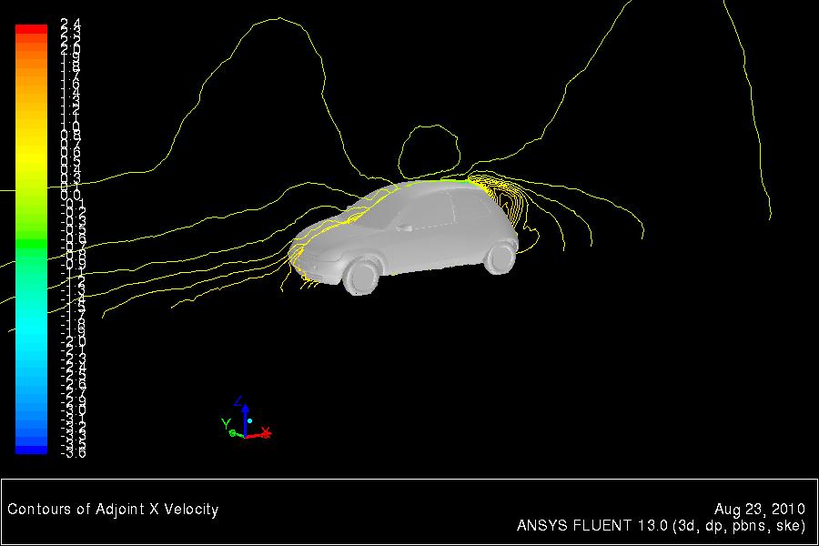
47 Example 1: Automotive Aerodynamics Surface map of the drag sensitivity to shape changes 48 Surface map of the drag sensitivity to shape changes Surface map of the drag sensitivity to shape changes
 Geometry")


48 Example 2: Pressure Drop in a Duct Total Pressure Drop (Pa) Geometry Predicted Result Original Modified Aggressive adjustment results in a 17% reduction in loss in just one design iteration 49
49 HPC Best Practices 50
50 Guidelines : Know your hardware lifecycle Have a goal in mind for what you want to achieve Using Licensing productively Using ANSYS provided processes effectively 51
51 Hardware Considerations This section is meant to provide an overview of the different hardware components and how they can effect solution time. Hopefully this will give you some of the tools to understand why some of the benchmark numbers in better detail. ANSYS would always recommend that the best thing to do before buying a system is to look at the latest benchmarks. If you are not sure please ask. 52
52 Effect of Clock Speed Impact of CPU Clock on Application Performance Processor: Xeon X5600 Series Hyper Threading: OFF, TURBO: ON Active cores: 12/node; Memory speed: 1333 MHz (performance measure is improvement relative to CPU Clock 2.66 GHz) Higher is better Improvement due to Clock GHz 2.93 GHz 3.47 GHz Clock Ratio eddy_417k aircraft_2m turbo_500k sedan_4m truck_14m ANSYS/FLUENT Model 53
53 Effect of Memory Speed We can see here the effect of memory speed. This has implications on how you build your hardware. Some processors types have slower memory speeds by default. On other processors nonoptimally filling the memory channels can slow the memory speed. Impact of Memory Speed 130% 125% 120% 115% 110% 105% 100% 95% 90% 85% 80% Impact of DIMM speed on ANSYS/FLUENT Application Performance (Intel Xeon x5670, 2.93 GHz) Hyper Threading: OFF, TURBO: ON Active threads per node: 12 (performance measure improvement is relative to memory speed of 1066 MHz) eddy_417k turbo_500k aircraft_2m sedan_4m truck_14m ANSYS/FLUENT Model 1066 MHz 1333 MHz 54


54 Turbo Boost (Intel) / Turbo Core (AMD) Turbo Boost (Intel)/ Turbo Core(AMD) is a form of over-clocking that allows you to give more GHz to individual processors when others are idle. With the Intel s have seen variable performance with this ranging between 0-8% improvement depending on the numbers of cores in use. The graph below for CFX on a Intel X5550. This only sees a maximum of 2.5% improvement. 55

55 Hyper-Threading: ANSYS Fluent Hyper-Threading Technology makes a single physical processor appear as two logical processors. Evaluation of Hyperthreading on ANSYS/FLUENT Performance idataplex M3 (Intel Xeon x5670, 2.93 GHz) TURBO: ON (measurement is improvement relative ot Hyperthtreading OFF) This is not the same as physically having two logical processors and does not give double the speedup. In our tests we ve seen as high as a 20% increase in performance although you can see the actual performance can be quite variable from the graph opposite. It is worth noting that this has licensing implications as you would need to oversubscribe the physical cores and hence would need double the HPC Licenses. Higher is better Improvemet due to Hyperthreading HT OFF (12 threads on 12 physical cores) HT ON (24 threads on 12 physical cores) eddy_417k turbo_500k aircraft_2m sedan_4m truck_14m ANSYS/FLUENT Model 56
56 AMD vs. Intel Traditionally Intel take the power approach in general in their 2 socket systems (faster core but less of them per processor/socket). Traditionally AMD take the economies of scale approach (more cores per processor but individually slower clock speeds). Remember that this landscape changes because they are constantly in competition with each other. Please note that whilst we do have some numbers for the new Intel Sandy-bridge chips we do not have scaling numbers for the equivalent AMD 6200 series at the time of writing this presentation. 57
57 2 Socket vs. 4 Socket Systems Current 4 socket systems come up slower than their 2 socket counterparts (based on Intel Westmere vs. Xeon E7-8837). Clock speed slower Memory speed slower No additional memory bandwidth. Performance of ANSYS Fluent on two-socket and four-socket based systems Performance measure is Fluent Rating (higher values are better) 2-socket based Systems IBM HS22/HS22V Blade, 3550/3650 M3, Dx360 M3 (Xeon 5600 Series) 4-socket based Systems IBM HX5 Blade, X3850 (Xeon E series) Nodes Sockets Cores Fluent Fluent Nodes Sockets Cores Rating Rating
58 Effect of the Interconnect When going for multiple systems linked together the interconnect becomes an important factor. The interconnect is the fabric that connects the nodes. We can see from the graph opposite with FLUENT how quickly the performance of Gigabit Ethernet drops off. FLUENT Rating Higher is better ANSYS/FLUENT Performance idataplex M3 (Intel Xeon x5670, 12C 2.93 GHz) Network: Gigabit, 10-Gigabit, 4X QDR Infiniband (QLogic, Voltaire) Hyperthreading: OFF, TURBO: ON Models: truck_14m QLogic Voltaire 10-Gigabit Gigabit Number of Cores used by a single job 59

59 ANSYS Fluent Auto-Partitioning Time to Partition cavity 200M case, Cavity 768 Case cores over 768 cores Auto partitioning is now very quick Less than 10s to process 800M cells! Serial pre-partitioning step no longer required Time in seconds M 400M 600M 800M Time Time to Partition truck_111m 111M Truck Case 60 Time in seconds Time
 β Large case interpolation for cases with >~100M nodes Clean up of coupled partitioning")

60 ANSYS CFX Partitioning Optimize parallel partitioning in multi-core clusters (CFX) β Partitioner determines number of connections between partitions and optimizes part.-host assignments Re-use previous results to initialize calculations on large problem (CFX) β Large case interpolation for cases with >~100M nodes Clean up of coupled partitioning option for multi-domain cases (CFX) Eliminates isolated partition spots Dramatically reduced partitioning times for cases with fluid-solid interfaces and very large numbers of regions P2 P1 P4 P3 P1 P5 P6 P5 P3 P6 P7 P8 Partitioning step finds adjacency amongst partitions; partitions with max adjacency are grouped on same compute nodes P2 P4 P7 P8 Compute Node 1 Compute Node 2 61
 2000 1000 0 70000 60000 50000 0 100 200 300 400 500 600 Intel Westmere 15000 10000 12.0.0 13.0.0 40000 30000 13.0.0 14.0.0 20000 5000 10000 62 0 0 2011 100 ANSYS, 200 Inc.")
61 ANSYS Fluent Parallel Scalability Consistently improved scalability across releases Intel Harpertown Sedan, 4M cells Xeon 2.80GHz (Nehalem EP) Intel Westmere ANSYS, 200 Inc. 300 May 4009,
62 ANSYS Fluent Parallel Scalability Consistently improved scalability across releases Truck, 111M cells Intel Harpertown SGI ICE 8400EX, Intel 6-core Intel Westmere hex-core 2.93 GHz ANSYS, 500 Inc May ,
63 ANSYS Fluent Parallel Scalability on Intel ANSYS Fluent 14 Relative Performance Higher is better Geomean core Xeon X core Xeon E Geomean 1 Sedan_4m Truck_14m 1.53 Leading Performance for fluid flow simulation The memory bandwidth of the Intel Xeon processor E product family allows excellent scalability and per core performance. Support for higher speed memory DIMMs, added on-core capacity for memory loads, as well as a larger cache size are key to extending performance and scalability. Higher memory bandwidth has a pronounced impact with fully coupled solver applications, which are the most memory intensive. Sedan_4m is shown as an example of fully coupled solver performance. Truck_14m is representative of segregated solver performance. The horizontal line at 1.63 represents the geomean speedup over 6 standard benchmarks. 6 core Xeon X core Xeon E Data Source: Approved/published results as of February 1, 2012 See backup for details 64 *Other names and brands may be claimed as the property of others
64 ANSYS CFX Parallel Scalability on Intel Intel Xeon 5650 Intel Xeon E Good scalability and more operations per clock make obtaining results on Intel Xeon E5 1.68x faster than on Intel Xeon 5600 platforms For end user it is about faster turnaround or solving larger tasks with the same resources along with lower TCO 65 0 AirliftReactor BigPipe CombBVM CombEDM Cylinder IndyCar Internal LeMansCar LES_001 Pump RadCity RadFurnace StageCompressor StaticMixer100MM StaticMixer100 StaticMixer200 StaticMixer 400k Turbine Wigley100 Source: Published/submitted/approved results as of March 6, Software and workloads used in performance tests may have been optimized for performance only on Intel microprocessors. Performance tests, such as SYSmark and MobileMark, are measured using specific computer systems, components, software, operations and functions. Any change to any of those factors may cause the results to vary. You should consult other information and performance tests to assist you in fully evaluating your contemplated purchases, including the performance of that product when combined with other products. Configuration Details: Please reference speaker note. For more information go to *Other names and brands may be claimed as the property of others


65 Including Monitors 3072 cores Scalability with Monitors Scalability to higher core counts Simulations with monitors including plotting and printing Hex-core mesh, F1 car, 130 million cells monitor-enabled Example data for scaling with R14 monitors Monitor support optimizations maintain scalability expectations 66

.")
66 Fluids I/O 67 FLUENT, CFX and AUTODYN use a singular file structure. This means there is one global set of files and every process writes to them. This methodology falls down at a large number of cores where the file I/O becomes a bottleneck. CFX deals with this by using inline compression (cdat) FLUENT has both inline compression (cdat) and at v12.x introduced support for a Parallel File (pdat). Parallel file system support in ANSYS FLUENT ~10x - 20x speedup for data write Eliminates scaling bottleneck for data intensive simulations on large clusters (e.g., transient flows) Serial I/O ANSYS FLUENT Parallel I/O
 to define shape")
 To drive shape parameters To create DOE To perform Goal Driven")


67 HPC Fluids Demonstration Case To Demonstrate 50:50:50 Method Volvo XC60 vehicle model Four shape parameters RBF Morph (Integrated within FLUENT) to define shape parameters Grid morphing in parallel ANSYS WorkBench (Frame Work to Automate Process) To drive shape parameters To create DOE To perform Goal Driven Optimization The 50:50:50 Method 50 design points in the design space 50 million cells used in CFD simulation of each design point 50 hours total elapsed time to simulate all the design points EXTENT ACCURACY SPEED One Click Entire design space is simulated and postprocessed completely automatically after the initial baseline case setup 68
, Optimizer (DX) & Post Processor (CFD Post) Morph Integrated Vehicle within Shape ANSYS WorkBench Run CFD Simulation STEP 5 Collate Data, Perform")
68 HPC Fluids Demonstration Case STEP 1 Prepare Meshed Model for Baseline Vehicle Shape STEP 2 CFD Solver Setup, Define Shape Parameters STEP 3 Generate DOE using Input Shape Parameters STEP 4 Mesh Morpher Integrated within FLUENT Solver (FLUENT), Optimizer (DX) & Post Processor (CFD Post) Morph Integrated Vehicle within Shape ANSYS WorkBench Run CFD Simulation STEP 5 Collate Data, Perform Optimization 69
69 HPC Fluids Demonstration Case 768 Cores 384 Cores 288 Cores 240 Cores 144 Cores Task Time (Seconds) Time (Seconds) Time (Seconds) Time (Seconds) Time (Seconds) Read volume mesh of baseline case into the CFD solver and apply solver settings Baseline Case (i.e. Design Point 1) CFD Solution Writing CFD data file Each Subsequent Design Point Morph vehicle shape CFD Solution Writing CFD data file Total Run Time (Wall Clock) Needed for All 50 Design Points (Hours)
70 HPC Fluids Demonstration Case Compute Cluster Details 1. Intel s Endeavor Cluster 2. Intel Xeon X5670 (dual socket) 3. Clock speed 2.93 GHz 4. Six cores per socket (12 cores per node) GB 1333 MHz, SMT ON, Turbo ON 6. QDR Infiniband 7. RHEL Server Release

71 GPU Acceleration for CFD Radiation viewfactor calculation (ANSYS FLUENT 14 - beta) First capability for specialty physics view factors, ray tracing, reaction rates, etc. R&D focus on linear solvers, smoothers but potential limited by Amdahl s Law 72

72 Getting the right setup is balancing act.. 73
73 Factors to Consider HPC Licensing Cost Cost of Hardware Complexity of Deployment and Maintenance 74
74 HPC Licensing Cost ANSYS HPC is licensed in either the HPC Workgroup/Enterprise (or individually) or HPC Packs. Given that it is licensed per partition (which in most cases translated to a core) the best value for money is in getting the best scalability per core as possible. When running multiple cores make sure you are using them as effectively as the memory bandwidth allows. 75
75 Cost of Hardware ANSYS will, in general, recommend the best hardware for performance that gets you the best out of your licensing investment. However you may need to make trade-off's for your budget. 2 socket systems provide the best performance but more inherently more complexity (and hence cost) because of the need for high speed interconnects when in a cluster. Current 4 socket systems have less performance than their 2 socket counterparts but are also cheaper because of their lack of requirement for the high speed interconnects to get to higher numbers of nodes at the low end. 76
76 Complexity of Deployment and Maintenance A large cluster can have significant overheads in ease of deployment & on-going maintenance costs. A 4 socket system, whilst having less performance, may provide an easier deployment and maintenance route at the lower end and will be a better fit to what the average IT department is used to. Often users get too caught up on per core performance at the detriment of not getting any extra speedup at all. It is important to purchase something you feel you can internally support. Purchase 3 rd party support for high performance clusters if you do not feel you have the skills to support it internally. 77
77 Remember the Following... If you opt for unsupported infrastructure This does not mean that it will not work but you use them at your own risk. We may ask you to replicate it on a system that is supported before providing further support if you run into problems! We recommend: Buying Supported Operating systems and Hardware Using ANSYS Supported Practices Talking to us before buying! It is in all our interests that you get this right! 78


78 Information Available ANSYS Partner Solutions Reference configurations Performance data White papers Sales contact points Performance Data 79


79 Information Available ANSYS Platform Support Platform Support Policies Supported Platforms Supported Hardware Tested systems ANSYS Virtual Demo Room Click on HPC! 80


 ANSYS Advantage")
80 Information Available The Manual Sections on best practices and parallel processing for various solvers Installation walkthroughs for installing the products, parallel processing, licensing and RSM (remote solve manager) ANSYS Advantage Online Magazine 81


81 Information Available Customer Portal Knowledge Resources Installation and Systems FAQ s Customer Support Portal, or Phone 82 Global ANSYS network providing Comprehensive Support
Mesh Morphing and the Adjoint Solver in ANSYS R14.0. Simon Pereira Laz Foley
 Mesh Morphing and the Adjoint Solver in ANSYS R14.0 Simon Pereira Laz Foley 1 Agenda Fluent Morphing-Optimization Feature RBF Morph with ANSYS DesignXplorer Adjoint Solver What does an adjoint solver do,
Automated Design Exploration and Optimization. Clinton Smith, PhD CAE Support and Training PADT April 26, 2012
 Automated Design Exploration and Optimization Clinton Smith, PhD CAE Support and Training PADT April 26, 2012 1 Agenda The path to robust design A closer look at what DX offers Some examples 2 The Path
Shape optimisation using breakthrough technologies
 Shape optimisation using breakthrough technologies Compiled by Mike Slack Ansys Technical Services 2010 ANSYS, Inc. All rights reserved. 1 ANSYS, Inc. Proprietary Introduction Shape optimisation technologies
RBF Morph An Add-on Module for Mesh Morphing in ANSYS Fluent
 RBF Morph An Add-on Module for Mesh Morphing in ANSYS Fluent Gilles Eggenspieler Senior Product Manager 1 Morphing & Smoothing A mesh morpher is a tool capable of performing mesh modifications in order
Automated Design Exploration and Optimization + HPC Best Practices
 Automated Design Exploration and Optimization + HPC Best Practices 1 2011 ANSYS, Inc. June 8, 2012 Laz Foley & Simon Pereira Confidence by Design Detroit June 5, 2012 Outline The Path to Robust Design
IBM Information Technology Guide For ANSYS Fluent Customers
 IBM ISV & Developer Relations Manufacturing IBM Information Technology Guide For ANSYS Fluent Customers A collaborative effort between ANSYS and IBM 2 IBM Information Technology Guide For ANSYS Fluent
Design Exploration and Robust Design. Judd Kaiser Product Manager, ANSYS Workbench Platform
 Design Exploration and Robust Design Judd Kaiser Product Manager, ANSYS Workbench Platform 1 Agenda 2 What is Robust Design? At ANSYS Workbench Principles DesignXplorer ANSYS Vision What is Robust Design?
Optimisationfor CFD. ANSYS R14 Fluids Update Seminar. Milton Park, February 16 th, 2012 Sheffield, February 29 th, 2012 Aberdeen, March 8 th, 2012
 Optimisationfor CFD ANSYS R14 Fluids Update Seminar David Mann, ANSYS UK Ltd. Milton Park, February 16 th, 2012 Sheffield, February 29 th, 2012 Aberdeen, March 8 th, 2012 1 Agenda Optimisation Tools for
ANSYS HPC Technology Leadership
 ANSYS HPC Technology Leadership 1 ANSYS, Inc. November 14, Why ANSYS Users Need HPC Insight you can t get any other way It s all about getting better insight into product behavior quicker! HPC enables
HPC and IT Issues Session Agenda. Deployment of Simulation (Trends and Issues Impacting IT) Mapping HPC to Performance (Scaling, Technology Advances)
 Mapping HPC to Performance (Scaling, Technology Advances)") HPC and IT Issues Session Agenda Deployment of Simulation (Trends and Issues Impacting IT) Discussion Mapping HPC to Performance (Scaling, Technology Advances) Discussion Optimizing IT for Remote Access
HPC and IT Issues Session Agenda Deployment of Simulation (Trends and Issues Impacting IT) Discussion Mapping HPC to Performance (Scaling, Technology Advances) Discussion Optimizing IT for Remote Access
Adjoint Solver Workshop
 Adjoint Solver Workshop Why is an Adjoint Solver useful? Design and manufacture for better performance: e.g. airfoil, combustor, rotor blade, ducts, body shape, etc. by optimising a certain characteristic
ANSYS HPC. Technology Leadership. Barbara Hutchings ANSYS, Inc. September 20, 2011
 ANSYS HPC Technology Leadership Barbara Hutchings barbara.hutchings@ansys.com 1 ANSYS, Inc. September 20, Why ANSYS Users Need HPC Insight you can t get any other way HPC enables high-fidelity Include
An advanced RBF Morph application: coupled CFD-CSM Aeroelastic Analysis of a Full Aircraft Model and Comparison to Experimental Data
 An advanced RBF Morph application: coupled CFD-CSM Aeroelastic Analysis of a Full Aircraft Model and Comparison to Experimental Data Dr. Marco Evangelos Biancolini Tor Vergata University, Rome, Italy Dr.
Speed and Accuracy of CFD: Achieving Both Successfully ANSYS UK S.A.Silvester
 Speed and Accuracy of CFD: Achieving Both Successfully ANSYS UK S.A.Silvester 2010 ANSYS, Inc. All rights reserved. 1 ANSYS, Inc. Proprietary Content ANSYS CFD Introduction ANSYS, the company Simulation
Real Application Performance and Beyond
 Real Application Performance and Beyond Mellanox Technologies Inc. 2900 Stender Way, Santa Clara, CA 95054 Tel: 408-970-3400 Fax: 408-970-3403 http://www.mellanox.com Scientists, engineers and analysts
Coupled Analysis of FSI
 Coupled Analysis of FSI Qin Yin Fan Oct. 11, 2008 Important Key Words Fluid Structure Interface = FSI Computational Fluid Dynamics = CFD Pressure Displacement Analysis = PDA Thermal Stress Analysis = TSA
Introduction to ANSYS CFX
 Workshop 03 Fluid flow around the NACA0012 Airfoil 16.0 Release Introduction to ANSYS CFX 2015 ANSYS, Inc. March 13, 2015 1 Release 16.0 Workshop Description: The flow simulated is an external aerodynamics
Understanding Hardware Selection to Speedup Your CFD and FEA Simulations
 Understanding Hardware Selection to Speedup Your CFD and FEA Simulations 1 Agenda Why Talking About Hardware HPC Terminology ANSYS Work-flow Hardware Considerations Additional resources 2 Agenda Why Talking
Maximize automotive simulation productivity with ANSYS HPC and NVIDIA GPUs
 Presented at the 2014 ANSYS Regional Conference- Detroit, June 5, 2014 Maximize automotive simulation productivity with ANSYS HPC and NVIDIA GPUs Bhushan Desam, Ph.D. NVIDIA Corporation 1 NVIDIA Enterprise
Solving Large Complex Problems. Efficient and Smart Solutions for Large Models
 Solving Large Complex Problems Efficient and Smart Solutions for Large Models 1 ANSYS Structural Mechanics Solutions offers several techniques 2 Current trends in simulation show an increased need for
HPC and IT Issues Session Agenda. Deployment of Simulation (Trends and Issues Impacting IT) Mapping HPC to Performance (Scaling, Technology Advances)
 Mapping HPC to Performance (Scaling, Technology Advances)") HPC and IT Issues Session Agenda Deployment of Simulation (Trends and Issues Impacting IT) Discussion Mapping HPC to Performance (Scaling, Technology Advances) Discussion Optimizing IT for Remote Access
HPC and IT Issues Session Agenda Deployment of Simulation (Trends and Issues Impacting IT) Discussion Mapping HPC to Performance (Scaling, Technology Advances) Discussion Optimizing IT for Remote Access
ANSYS AIM 16.0 Overview. AIM Program Management
 1 2015 ANSYS, Inc. September 27, 2015 ANSYS AIM 16.0 Overview AIM Program Management 2 2015 ANSYS, Inc. September 27, 2015 Today s Simulation Challenges Leveraging simulation across engineering organizations
Answers to Webinar "Wind farm flow modelling using CFD update" Q&A session
 Answers to Webinar "Wind farm flow modelling using CFD - 2012 update" Q&A session Christiane Montavon, Ian Jones Physics related Q: Should the roughness map be scaled from the normal WAsP map to the CFD
Engineers can be significantly more productive when ANSYS Mechanical runs on CPUs with a high core count. Executive Summary
 white paper Computer-Aided Engineering ANSYS Mechanical on Intel Xeon Processors Engineer Productivity Boosted by Higher-Core CPUs Engineers can be significantly more productive when ANSYS Mechanical runs
Shape Optimization for Aerodynamic Efficiency Using Adjoint Methods
 White Paper Shape Optimization for Aerodynamic Efficiency Using Adjoint Methods Adjoint solvers take a Computational Fluid Dynamics (CFD) flow solution and calculate the sensitivity of performance indicators
You will not hear hold music while waiting for the event to begin.
 To hear today s event : Listen via the audio stream through your computer speakers OR Listen via phone by clicking the teleconference request button in the Participants window You will not hear hold music
Topology Optimization in Fluid Dynamics
 A Methodology for Topology Optimization in Fluid Dynamics 1 Chris Cowan Ozen Engineering, Inc. 1210 E. Arques Ave, Suite 207 Sunnyvale, CA 94085 info@ozeninc.com Ozen Engineering Inc. We are your local
RBF Morph: mesh morphing in OpenFoam
 RBF Morph: mesh morphing in OpenFoam Dr. Marco Evangelos Biancolini University of Rome Tor Vergata @ CINECA, 26-28 March 2014 Cineca - BOLOGNA RBF Morph Training PRACE School 2013 Session #1 General Introduction
Enhancing Analysis-Based Design with Quad-Core Intel Xeon Processor-Based Workstations
 Performance Brief Quad-Core Workstation Enhancing Analysis-Based Design with Quad-Core Intel Xeon Processor-Based Workstations With eight cores and up to 80 GFLOPS of peak performance at your fingertips,
Why HPC for. ANSYS Mechanical and ANSYS CFD?
 Why HPC for ANSYS Mechanical and ANSYS CFD? 1 HPC Defined High Performance Computing (HPC) at ANSYS: An ongoing effort designed to remove computing limitations from engineers who use computer aided engineering
Introduction to C omputational F luid Dynamics. D. Murrin
 Introduction to C omputational F luid Dynamics D. Murrin Computational fluid dynamics (CFD) is the science of predicting fluid flow, heat transfer, mass transfer, chemical reactions, and related phenomena
Commercial Implementations of Optimization Software and its Application to Fluid Dynamics Problems
 Commercial Implementations of Optimization Software and its Application to Fluid Dynamics Problems Szymon Buhajczuk, M.A.Sc SimuTech Group Toronto Fields Institute Optimization Seminar December 6, 2011
ANSYS High. Computing. User Group CAE Associates
 ANSYS High Performance Computing User Group 010 010 CAE Associates Parallel Processing in ANSYS ANSYS offers two parallel processing methods: Shared-memory ANSYS: Shared-memory ANSYS uses the sharedmemory
Recent Advances in ANSYS Toward RDO Practices Using optislang. Wim Slagter, ANSYS Inc. Herbert Güttler, MicroConsult GmbH
 Recent Advances in ANSYS Toward RDO Practices Using optislang Wim Slagter, ANSYS Inc. Herbert Güttler, MicroConsult GmbH 1 Product Development Pressures Source: Engineering Simulation & HPC Usage Survey
Dell EMC Ready Bundle for HPC Digital Manufacturing ANSYS Performance
 Dell EMC Ready Bundle for HPC Digital Manufacturing ANSYS Performance This Dell EMC technical white paper discusses performance benchmarking results and analysis for ANSYS Mechanical, ANSYS Fluent, and
Adjoint Solver Advances, Tailored to Automotive Applications
 Adjoint Solver Advances, Tailored to Automotive Applications Stamatina Petropoulou s.petropoulou@iconcfd.com 1 Contents 1. Icon s Principal Work in FlowHead 2. Demonstration Cases 3. Icon s Further Development
The Cray CX1 puts massive power and flexibility right where you need it in your workgroup
 The Cray CX1 puts massive power and flexibility right where you need it in your workgroup Up to 96 cores of Intel 5600 compute power 3D visualization Up to 32TB of storage GPU acceleration Small footprint
Ansys Fluent R Michele Andreoli
 Ansys Fluent R 17.0 Michele Andreoli (m.andreoli@enginsoft.it) Table of contents User Interface Fluent Meshing Solver Numerics New features Innovative Solutions New User Interface: Ribbon-Driven Solver
Pressure Drop Evaluation in a Pilot Plant Hydrocyclone
 Pressure Drop Evaluation in a Pilot Plant Hydrocyclone Fabio Kasper, M.Sc. Emilio Paladino, D.Sc. Marcus Reis, M.Sc. ESSS Carlos A. Capela Moraes, D.Sc. Dárley C. Melo, M.Sc. Petrobras Research Center
Thank you for downloading one of our ANSYS whitepapers we hope you enjoy it.
 Thank you! Thank you for downloading one of our ANSYS whitepapers we hope you enjoy it. Have questions? Need more information? Please don t hesitate to contact us! We have plenty more where this came from.
ANSYS Fluid Structure Interaction for Thermal Management and Aeroelasticity
 ANSYS Fluid Structure Interaction for Thermal Management and Aeroelasticity Phil Stopford Duxford Air Museum 11th May 2011 2011 2010 ANSYS, Inc. All rights reserved. 1 ANSYS, Inc. Proprietary Fluid Structure
Parametric. Practices. Patrick Cunningham. CAE Associates Inc. and ANSYS Inc. Proprietary 2012 CAE Associates Inc. and ANSYS Inc. All rights reserved.
 Parametric Modeling Best Practices Patrick Cunningham July, 2012 CAE Associates Inc. and ANSYS Inc. Proprietary 2012 CAE Associates Inc. and ANSYS Inc. All rights reserved. E-Learning Webinar Series This
Flow and Heat Transfer in a Mixing Elbow
 Flow and Heat Transfer in a Mixing Elbow Objectives The main objectives of the project are to learn (i) how to set up and perform flow simulations with heat transfer and mixing, (ii) post-processing and
Using Multiple Rotating Reference Frames
 Tutorial 10. Using Multiple Rotating Reference Frames Introduction Many engineering problems involve rotating flow domains. One example is the centrifugal blower unit that is typically used in automotive
Maximize Performance and Scalability of RADIOSS* Structural Analysis Software on Intel Xeon Processor E7 v2 Family-Based Platforms
 Maximize Performance and Scalability of RADIOSS* Structural Analysis Software on Family-Based Platforms Executive Summary Complex simulations of structural and systems performance, such as car crash simulations,
CFD Topological Optimization of a Car Water-Pump Inlet using TOSCA Fluid and STAR- CCM+
 CFD Topological Optimization of a Car Water-Pump Inlet using TOSCA Fluid and STAR- CCM+ Dr. Anselm Hopf Dr. Andrew Hitchings Les Routledge Ford Motor Company CONTENTS Introduction/Motivation Optimization
OzenCloud Case Studies
 OzenCloud Case Studies Case Studies, April 20, 2015 ANSYS in the Cloud Case Studies: Aerodynamics & fluttering study on an aircraft wing using fluid structure interaction 1 Powered by UberCloud http://www.theubercloud.com
Introduction to CFX. Workshop 2. Transonic Flow Over a NACA 0012 Airfoil. WS2-1. ANSYS, Inc. Proprietary 2009 ANSYS, Inc. All rights reserved.
 Workshop 2 Transonic Flow Over a NACA 0012 Airfoil. Introduction to CFX WS2-1 Goals The purpose of this tutorial is to introduce the user to modelling flow in high speed external aerodynamic applications.
KEYWORDS Morphing, CAE workflow, Optimization, Automation, DOE, Regression, CFD, FEM, Python
 DESIGN OPTIMIZATION WITH ANSA MORPH 1 Tobias Eidevåg *, 1 David Tarazona Ramos *, 1 Mohammad El-Alti 1 Alten AB, Sweden KEYWORDS Morphing, CAE workflow, Optimization, Automation, DOE, Regression, CFD,
Auto Injector Syringe. A Fluent Dynamic Mesh 1DOF Tutorial
 Auto Injector Syringe A Fluent Dynamic Mesh 1DOF Tutorial 1 2015 ANSYS, Inc. June 26, 2015 Prerequisites This tutorial is written with the assumption that You have attended the Introduction to ANSYS Fluent
AcuSolve Performance Benchmark and Profiling. October 2011
 AcuSolve Performance Benchmark and Profiling October 2011 Note The following research was performed under the HPC Advisory Council activities Participating vendors: AMD, Dell, Mellanox, Altair Compute
ANSYS Improvements to Engineering Productivity with HPC and GPU-Accelerated Simulation
 ANSYS Improvements to Engineering Productivity with HPC and GPU-Accelerated Simulation Ray Browell nvidia Technology Theater SC12 1 2012 ANSYS, Inc. nvidia Technology Theater SC12 HPC Revolution Recent
Accelerating Implicit LS-DYNA with GPU
 Accelerating Implicit LS-DYNA with GPU Yih-Yih Lin Hewlett-Packard Company Abstract A major hindrance to the widespread use of Implicit LS-DYNA is its high compute cost. This paper will show modern GPU,
Performance Optimizations via Connect-IB and Dynamically Connected Transport Service for Maximum Performance on LS-DYNA
 Performance Optimizations via Connect-IB and Dynamically Connected Transport Service for Maximum Performance on LS-DYNA Pak Lui, Gilad Shainer, Brian Klaff Mellanox Technologies Abstract From concept to
Using a Single Rotating Reference Frame
 Tutorial 9. Using a Single Rotating Reference Frame Introduction This tutorial considers the flow within a 2D, axisymmetric, co-rotating disk cavity system. Understanding the behavior of such flows is
Tutorial 1. Introduction to Using FLUENT: Fluid Flow and Heat Transfer in a Mixing Elbow
 Tutorial 1. Introduction to Using FLUENT: Fluid Flow and Heat Transfer in a Mixing Elbow Introduction This tutorial illustrates the setup and solution of the two-dimensional turbulent fluid flow and heat
Swapnil Nimse Project 1 Challenge #2
 Swapnil Nimse Project 1 Challenge #2 Project Overview: Using Ansys-Fluent, analyze dependency of the steady-state temperature at different parts of the system on the flow velocity at the inlet and buoyancy-driven
This tutorial illustrates how to set up and solve a problem involving solidification. This tutorial will demonstrate how to do the following:
 Tutorial 22. Modeling Solidification Introduction This tutorial illustrates how to set up and solve a problem involving solidification. This tutorial will demonstrate how to do the following: Define a
QLogic TrueScale InfiniBand and Teraflop Simulations
 WHITE Paper QLogic TrueScale InfiniBand and Teraflop Simulations For ANSYS Mechanical v12 High Performance Interconnect for ANSYS Computer Aided Engineering Solutions Executive Summary Today s challenging
Using Multiple Rotating Reference Frames
 Tutorial 9. Using Multiple Rotating Reference Frames Introduction Many engineering problems involve rotating flow domains. One example is the centrifugal blower unit that is typically used in automotive
AcuSolve Performance Benchmark and Profiling. October 2011
 AcuSolve Performance Benchmark and Profiling October 2011 Note The following research was performed under the HPC Advisory Council activities Participating vendors: Intel, Dell, Mellanox, Altair Compute
Automotive Fluid-Structure Interaction (FSI) Concepts, Solutions and Applications. Laz Foley, ANSYS Inc.
 Concepts, Solutions and Applications. Laz Foley, ANSYS Inc.") Automotive Fluid-Structure Interaction (FSI) Concepts, Solutions and Applications Laz Foley, ANSYS Inc. Outline FSI Classifications FSI Solutions FSI Modeling Approaches ANSYS Workbench for FSI System
Automotive Fluid-Structure Interaction (FSI) Concepts, Solutions and Applications Laz Foley, ANSYS Inc. Outline FSI Classifications FSI Solutions FSI Modeling Approaches ANSYS Workbench for FSI System
Industrial finite element analysis: Evolution and current challenges. Keynote presentation at NAFEMS World Congress Crete, Greece June 16-19, 2009
 Industrial finite element analysis: Evolution and current challenges Keynote presentation at NAFEMS World Congress Crete, Greece June 16-19, 2009 Dr. Chief Numerical Analyst Office of Architecture and
NUMERICAL INVESTIGATION OF THE FLOW BEHAVIOR INTO THE INLET GUIDE VANE SYSTEM (IGV)
") University of West Bohemia» Department of Power System Engineering NUMERICAL INVESTIGATION OF THE FLOW BEHAVIOR INTO THE INLET GUIDE VANE SYSTEM (IGV) Publication was supported by project: Budování excelentního
University of West Bohemia» Department of Power System Engineering NUMERICAL INVESTIGATION OF THE FLOW BEHAVIOR INTO THE INLET GUIDE VANE SYSTEM (IGV) Publication was supported by project: Budování excelentního
First Steps - Ball Valve Design
 COSMOSFloWorks 2004 Tutorial 1 First Steps - Ball Valve Design This First Steps tutorial covers the flow of water through a ball valve assembly before and after some design changes. The objective is to
Missile External Aerodynamics Using Star-CCM+ Star European Conference 03/22-23/2011
 Missile External Aerodynamics Using Star-CCM+ Star European Conference 03/22-23/2011 StarCCM_StarEurope_2011 4/6/11 1 Overview 2 Role of CFD in Aerodynamic Analyses Classical aerodynamics / Semi-Empirical
Automatic & Robust Meshing in Fluids 2011 ANSYS Regional Conferences
 Automatic & Robust Meshing in Fluids 2011 ANSYS Regional Conferences 1 This is just a taste Note that full 14.0 update webinars of an hour per product will be scheduled closer to the release This presentation
Simulating Sinkage & Trim for Planing Boat Hulls. A Fluent Dynamic Mesh 6DOF Tutorial
 Simulating Sinkage & Trim for Planing Boat Hulls A Fluent Dynamic Mesh 6DOF Tutorial 1 Introduction Workshop Description This workshop describes how to perform a transient 2DOF simulation of a planing
Turbocharger Design & Analysis Solutions. Bill Holmes Brad Hutchinson Detroit, October 2012
 Turbocharger Design & Analysis Solutions Bill Holmes Brad Hutchinson Detroit, October 2012 Agenda ANSYS overview ANSYS TurboSystem Blade row solutions The ANSYS Transformation methods An example: turbocharger
A Comprehensive Study on the Performance of Implicit LS-DYNA
 12 th International LS-DYNA Users Conference Computing Technologies(4) A Comprehensive Study on the Performance of Implicit LS-DYNA Yih-Yih Lin Hewlett-Packard Company Abstract This work addresses four
DYNARDO Dynardo GmbH CFD Examples. Dr.-Ing. Johannes Will President Dynardo GmbH
 CFD Examples Dr.-Ing. Johannes Will President Dynardo GmbH 1 Flow Simulation of LCD Manufacturing Process Task: - Optimization the flow conditions at a LCD manufacturing process - Inputs: - lab geometry
Overview and Recent Developments of Dynamic Mesh Capabilities
 Overview and Recent Developments of Dynamic Mesh Capabilities Henrik Rusche and Hrvoje Jasak h.rusche@wikki-gmbh.de and h.jasak@wikki.co.uk Wikki Gmbh, Germany Wikki Ltd, United Kingdom 6th OpenFOAM Workshop,
Fluid structure interaction analysis: vortex shedding induced vibrations
 Fluid structure interaction analysis: vortex shedding induced vibrations N. Di Domenico, M. E. * University of Rome «Tor Vergata», Department of Enterprise Engineering «Mario Lucertini» A. Wade, T. Berg,
Webinar: TwinMesh for Reliable CFD Analysis of Rotating Positive Displacement Machines
 Webinar: TwinMesh for Reliable CFD Analysis of Rotating Positive Displacement Machines 14.07.2015 Dipl.-Ing. Jan Hesse Jan.hesse@cfx-berlin.de CFX Berlin Software GmbH Karl-Marx-Allee 90 A 10243 Berlin
ANSYS FLUENT. Airfoil Analysis and Tutorial
 ANSYS FLUENT Airfoil Analysis and Tutorial ENGR083: Fluid Mechanics II Terry Yu 5/11/2017 Abstract The NACA 0012 airfoil was one of the earliest airfoils created. Its mathematically simple shape and age
Speedup Altair RADIOSS Solvers Using NVIDIA GPU
 Innovation Intelligence Speedup Altair RADIOSS Solvers Using NVIDIA GPU Eric LEQUINIOU, HPC Director Hongwei Zhou, Senior Software Developer May 16, 2012 Innovation Intelligence ALTAIR OVERVIEW Altair
Automatic & Robust Meshing in Fluids 2011 ANSYS Regional Conferences
 Automatic & Robust Meshing in Fluids 2011 ANSYS Regional Conferences 1 Automatic & Robust Meshing Assembly Meshing Assembly Meshing enables dramatically reduced time to mesh for typical CAD models by eliminating
Modeling External Compressible Flow
 Tutorial 3. Modeling External Compressible Flow Introduction The purpose of this tutorial is to compute the turbulent flow past a transonic airfoil at a nonzero angle of attack. You will use the Spalart-Allmaras
HP ProLiant BladeSystem Gen9 vs Gen8 and G7 Server Blades on Data Warehouse Workloads
 HP ProLiant BladeSystem Gen9 vs Gen8 and G7 Server Blades on Data Warehouse Workloads Gen9 server blades give more performance per dollar for your investment. Executive Summary Information Technology (IT)
Estimating Vertical Drag on Helicopter Fuselage during Hovering
 Estimating Vertical Drag on Helicopter Fuselage during Hovering A. A. Wahab * and M.Hafiz Ismail ** Aeronautical & Automotive Dept., Faculty of Mechanical Engineering, Universiti Teknologi Malaysia, 81310
System Level Cooling, Fatigue, and Durability. Co-Simulation. Stuart A. Walker, Ph.D.
 System Level Cooling, Fatigue, and Durability Analysis via Multiphysics Co-Simulation Stuart A. Walker, Ph.D. swalker@altair.com Outline Motivation Presentation of process Presentation of tools Presentation
CFD Simulation of a dry Scroll Vacuum Pump including Leakage Flows
 CFD Simulation of a dry Scroll Vacuum Pump including Leakage Flows Jan Hesse, Rainer Andres CFX Berlin Software GmbH, Berlin, Germany 1 Introduction Numerical simulation results of a dry scroll vacuum
Dell EMC Ready Bundle for HPC Digital Manufacturing Dassault Systѐmes Simulia Abaqus Performance
 Dell EMC Ready Bundle for HPC Digital Manufacturing Dassault Systѐmes Simulia Abaqus Performance This Dell EMC technical white paper discusses performance benchmarking results and analysis for Simulia
2008 International ANSYS Conference
 28 International ANSYS Conference Maximizing Performance for Large Scale Analysis on Multi-core Processor Systems Don Mize Technical Consultant Hewlett Packard 28 ANSYS, Inc. All rights reserved. 1 ANSYS,
Maximizing Memory Performance for ANSYS Simulations
 Maximizing Memory Performance for ANSYS Simulations By Alex Pickard, 2018-11-19 Memory or RAM is an important aspect of configuring computers for high performance computing (HPC) simulation work. The performance
Aero-Vibro Acoustics For Wind Noise Application. David Roche and Ashok Khondge ANSYS, Inc.
 Aero-Vibro Acoustics For Wind Noise Application David Roche and Ashok Khondge ANSYS, Inc. Outline 1. Wind Noise 2. Problem Description 3. Simulation Methodology 4. Results 5. Summary Thursday, October
Introduction to ANSYS DesignXplorer
 Overview 14. 5 Release Introduction to ANSYS DesignXplorer 1 2013 ANSYS, Inc. September 27, 2013 What is DesignXplorer? DesignXplorer (DX) is a tool that uses response surfaces and direct optimization
TENDER FOR PURCHASE OF LICENSES OF FINITE ELEMENT ANALYSIS PROGRAM SPECIFICATIONS
 TENDER FOR PURCHASE OF LICENSES OF FINITE ELEMENT ANALYSIS PROGRAM SPECIFICATIONS 1. OVERVIEW 1.1. These specifications identify the minimum requirements for the Licenses of two Finite Element Analysis
Software within building physics and ground heat storage. HEAT3 version 7. A PC-program for heat transfer in three dimensions Update manual
 Software within building physics and ground heat storage HEAT3 version 7 A PC-program for heat transfer in three dimensions Update manual June 15, 2015 BLOCON www.buildingphysics.com Contents 1. WHAT S
ANSYS FLUENT. Lecture 3. Basic Overview of Using the FLUENT User Interface L3-1. Customer Training Material
 Lecture 3 Basic Overview of Using the FLUENT User Interface Introduction to ANSYS FLUENT L3-1 Parallel Processing FLUENT can readily be run across many processors in parallel. This will greatly speed up
SPC 307 Aerodynamics. Lecture 1. February 10, 2018
 SPC 307 Aerodynamics Lecture 1 February 10, 2018 Sep. 18, 2016 1 Course Materials drahmednagib.com 2 COURSE OUTLINE Introduction to Aerodynamics Review on the Fundamentals of Fluid Mechanics Euler and
Compressible Flow in a Nozzle
 SPC 407 Supersonic & Hypersonic Fluid Dynamics Ansys Fluent Tutorial 1 Compressible Flow in a Nozzle Ahmed M Nagib Elmekawy, PhD, P.E. Problem Specification Consider air flowing at high-speed through a
Computational Simulation of the Wind-force on Metal Meshes
 16 th Australasian Fluid Mechanics Conference Crown Plaza, Gold Coast, Australia 2-7 December 2007 Computational Simulation of the Wind-force on Metal Meshes Ahmad Sharifian & David R. Buttsworth Faculty
Making Supercomputing More Available and Accessible Windows HPC Server 2008 R2 Beta 2 Microsoft High Performance Computing April, 2010
 Making Supercomputing More Available and Accessible Windows HPC Server 2008 R2 Beta 2 Microsoft High Performance Computing April, 2010 Windows HPC Server 2008 R2 Windows HPC Server 2008 R2 makes supercomputing
CFD Optimisation case studies with STAR-CD and STAR-CCM+
 CFD Optimisation case studies with STAR-CD and STAR-CCM+ Summary David J. Eby, Preetham Rao, Advanced Methods Group, Plymouth, MI USA Presented by Fred Mendonça, CD-adapco London, UK Outline Introduction
Recent & Upcoming Features in STAR-CCM+ for Aerospace Applications Deryl Snyder, Ph.D.
 Recent & Upcoming Features in STAR-CCM+ for Aerospace Applications Deryl Snyder, Ph.D. Outline Introduction Aerospace Applications Summary New Capabilities for Aerospace Continuity Convergence Accelerator
Ashwin Shridhar et al. Int. Journal of Engineering Research and Applications ISSN : , Vol. 5, Issue 6, ( Part - 5) June 2015, pp.
 June 2015, pp.") RESEARCH ARTICLE OPEN ACCESS Conjugate Heat transfer Analysis of helical fins with airfoil crosssection and its comparison with existing circular fin design for air cooled engines employing constant rectangular
RESEARCH ARTICLE OPEN ACCESS Conjugate Heat transfer Analysis of helical fins with airfoil crosssection and its comparison with existing circular fin design for air cooled engines employing constant rectangular
2008 International ANSYS Conference
 2008 International ANSYS Conference Simulation Driven Product Development using ANSYS Technology Padmesh Mandloi Rahul Kumar Samir Kadam 2008 ANSYS, Inc. All rights reserved. 1 ANSYS, Inc. Proprietary
The viscous forces on the cylinder are proportional to the gradient of the velocity field at the
 Fluid Dynamics Models : Flow Past a Cylinder Flow Past a Cylinder Introduction The flow of fluid behind a blunt body such as an automobile is difficult to compute due to the unsteady flows. The wake behind
Ultimate Workstation Performance
 Product brief & COMPARISON GUIDE Intel Scalable Processors Intel W Processors Ultimate Workstation Performance Intel Scalable Processors and Intel W Processors for Professional Workstations Optimized to