Chapter 9. NC Part Programming: Defining Geometry and Machining Plan (Motion)
|
|
|
- Natalie Patrick
- 5 years ago
- Views:
Transcription
1 Chapter 9. NC Part Programming: Defining Geometry and Machining Plan (Motion) NC Program Storage Media Punched Card Tape (one inch wide) Magnetic Tape Floppy Disk and CD Transfer data through RS-232 interface from controller to computer using such protocols as Kermit and Xmodem. Also, some machines use local area network (LAN) instead of serial communications. Symbolic Codes Binary-Coded Decimal (BCD): eight-track punched tape is one common input media for NC machines American Standard Code for Information Interchange (ASCII): was formulated in 1979 to standardize the punched codes, but this is also used in computers and telecommunications. Many new NC systems accept both BCD and ASCII codes.
2 Tape Input Format (organization of words within blocks)
3
4 Address: An identifying letter inserted in front of each word. Words: Each item of the program sheet, such as the sequence number, the preparatory (G) function, and the X position, forms one word on the tape. Blocks: A block consists of all the items or words needed to instruct the machine how to perform in any one position of the work piece. The way in which blocks are arranged along the length of the tape is known as the block format.
5 Four tape inputs are used for NC: Fixed sequential format requires each NC block be the same length requiring all values appear even if they are not required. Block address format eliminate the need for specifying redundant information in subsequent NC blocks through a change code. All data must contain a predefined number of digits. Tab sequential format has the words listed in a fixed sequence and separated by the tab key. Each tab will skip the redundant data.
6 Block Address Format and G-code program A block of NC part program consists of several words and a program written in this data format is called NC program (or simply g-code). A NC program can contain any of following word addresses (word = address + value). N,G,X,Y,Z,A,B,C,H,I,J,K,F,S,T,R,M,U,V,W N-code: The N-word specifies the sequence number to identify the block within the program. G-code (preparatory code): prepares the MCU for control functions.
7 X,Y,Z,A,B,C,U,V,W-codes: provide coordinate position of the tool. X,Y,Z are for translational (Cartesian) axes and A,B,C are for rotational axes about X,Y,Z axes. U,V,W are incremental X,Y,Z. Ex. Move the cutter to a new position (1.12, 2.275, 1.0) X1.12 Y2.275 Z1.0
![G-code [0-9] All G codes listed are for RS-274 compatible CNC controls.](/docs-images/82/87018126/images/8-3.jpg "Motion Class [G00 G09] G00: rapid traverse code (PTP) G01: linear interpolation G02: CW circular interpolation G03: CCW circular")
8 G-code [0-9] All G codes listed are for RS-274 compatible CNC controls. Motion Class [G00 G09] G00: rapid traverse code (PTP) G01: linear interpolation G02: CW circular interpolation G03: CCW circular interpolation G04: dwell G08: acceleration G09: deceleration

![[G10 - G19] G17: X-Y](/docs-images/82/87018126/images/9-4.jpg "plane G18: Z-X plane")
9 G10-G19 Presets and Plane Selection G-Codes [G10 - G19] G17: X-Y plane G18: Z-X plane G19: Y-Z plane
10 G20-29 Unit Selection G-Codes and Machine Coordinate Motion [G20 - G29]
11 G30-39 Feedrate Control and Threading [G30 G39]
![G40-49 Tool Compensation Codes [G40 - G49] G40: cutter compensation](/docs-images/82/87018126/images/12-3.jpg "cancel G41: cutter compensation left G42: cutter compensation right")
12 G40-49 Tool Compensation Codes [G40 - G49] G40: cutter compensation cancel G41: cutter compensation left G42: cutter compensation right
13 Tool Radius Compensation The tool compensation (sometimes, cutter radius compensation [CRC]) commands will effectively compensate the tool-path along the tool-path direction (the program knows all tool-paths). Start and End of Compensation If G41 or G42 and G01 are in the same block, there will be a gradual effect of compensation (ramp-up block). N0020 G01 G41 X0.500 Y2.000 N0030 G01 X2.500 M96 Note that the tool moves along the hypotenuse of a right triangle in the ramp compensation with right angle at the destination point.
14 If G41 or G42 and G01 are in separate blocks from X and Y, the compensation is effective from the start of the block N0010 G41 N0020 X0.500 Y2.000 N0030 G01 X2.500 G40 also works same way as G41 and G42 in opposite way. N0070 G40 X3.000 Y2.000 M02 N0070 X3.000 Y2.000 N0080 G40 M02
15 Cornering Fadal CNC Controls: Use of M96 and M97 with M96 the controller adds an additional block for circular arc at the corner, while with M97 the cutter moves to machining point. If a step to be machined is smaller than the cutter radius, M97 must be used instead of M96. Note that a fillet is used than sharp corner in design. For a 3D corner, both M96 and M97 produce different results as below.
16 Fanuc CNC Controls: Use of G09 or G61 and G64 Non-modal exact stop check command: G09 Modal exact stop check command: G61 and G64 (to cancel) G01 G09 X40 Note that G09 is effective after the motion to X40. Also, it is non-modal command and works only for one step while G61 is modal command and effective until it is cancelled.
![G50-59 Transformation and Coordinate System G-Codes [G50 - G59] G50,51: scaling and mirroring G52: shift](/docs-images/82/87018126/images/17-4.jpg "the workpiece zero (i.e., part zero) point of the program created in the work coordinate system (G54 - G59)")
17 G50-59 Transformation and Coordinate System G-Codes [G50 - G59] G50,51: scaling and mirroring G52: shift the workpiece zero (i.e., part zero) point of the program created in the work coordinate system (G54 - G59)


18 G60-69 Machine Specific G-Codes [G60 - G69] G65,66,67: macro programs G68,69: CS rotation code
19 G70-79 Repetitious Cycle G Codes [G70 - G79] G70: inch format G71: metric format G74: full circle programming off G75: full circle programming on
20 H,T,R-Codes H-code: used for tool length offset Ex. G43 H2 T-code: when automatic tool changer is available, T-code specifies the tool number. Ex. T2 M6 R-code: specifies the clearance height (i.e., R-plane) for cycle parameter such as drilling. Ex. N0020 G81 X1.0 Y2.0 Z0.0 R1.3 N0030 G80
21 M-Code M-code: machine-specific (i.e., vendor-specific) and used for miscellaneous words to control miscellaneous functions such as start on/off, spindle on/off, turn on/off the coolant, laser on/off, change the tool, and rewind the program. Some example codes are M00: program stop M01: Optional stop M02: end of the program M03: spindle CW M04: spindle CCW M06: tool change M07: flood coolant on M08: mist coolant on M09: coolant off M30: end of tape
22 Manual Part Programming (Motion) In manual programming, the machining instructions are recorded on a document called a part-program manuscript by the part programmer. Because a part program records a sequence of tool motions and operations to produce the final part geometry, one must prepare a process plan with setups and fixtures before writing the program where the workpiece location and orientation, features (holes, slots, pockets) to be machined, tools and cutting parameters used need to be determined.
23 Safety Blocks Safety Blocks at Beginning of the NC Code One good practice in writing NC part programs is that all NC programs should start with what are called Safety Blocks of G and M codes at the start of the NC program. Even though some CNC controls set motion and register defaults themselves at program start, not all do and keep using whatever parameters were active last time. One example of the safety block is shown below. N10 G90 G70 G40 G49 G17 G80 G53 G00 Here, G90 programming in absolute coordinates (incremental coordinates G91), G70 defines inch unit (G71 for metric unit), G40 cancels any XY cutter compensation, G49 cancels the tool length compensation [the tool length command is used mostly for multiple tool NC programs so that each tool will cut to the correct depth, regardless of how far it extends out of the holder], G17 sets the plane to the XY plane for arc motion, G80 cancels any canned drill cycles, G53 cancels any work coordinate shift, and add a default motion code by putting a G00 since the initial move is almost always a rapid position move from the home location to the program start point.

24 Program Entry Moves (NIST: National Institute of Standards and Technology) Two pre-entry moves and one entry move are generally required. Two methods, general method and simple method, are used for entry moves. N0010 G1 X1 Y5 (to C) N0020 G1 G41 Y4 (to B) N0030 G3 X2 Y3 I1 (to A)

25 Another case where the entry point is given on the concave arc as below can be handled in same way.

26

27 Ex.1. Part Programming for Laser Cutting The laser machining on a table is basically two-dimensional machining and can be assumed zero cutting width. The laser beam focal radius can be very small less than 1/1000 inch. The following is two-dimensional CAD drawing of a thin part. Make a part program to cut out the part by laser. Exclude the letters in the middle.
28 The following shows the sequence of cutting when a automatic converter software is used to convert the 2D drawing DXF file to NC file. The sequence depends on the order of the way the drawing was created. This is neither efficient nor correct. Keeping in mind that the outline must be machined last, make a program for continuous cutting when possible.
29 Geometries for Program
30 F100 L1 G92X0Y0 M88 G0 X Y M90 G2 X Y I J M91 G0 X Y M90 G1 X Y G1 X Y G1 X Y G1 X Y M91 G0 X Y M90 G1 X Y G1 X Y M91 G0 X Y M90 G1 X Y M91 M89 M30 F100: defines the feed rate 100 in/min G92: set a point as the new origin of coordinates that is referenced by subsequent absolute positioning L1: material selection defined previously M88: shutter open for smoke removal M89: shutter close M90: laser on for cutting M91: laser off Programming Tip 1. Cut the outline last 2. Make continuous cutting if possible
31 Ex.2 Fadal CNC Controls Example [NC Program with Fadal CNC Controls] Make a NC program for the following part with tool compensation. The tool diameter of #1 is 0.5 inch. The spindle speed is 5000 rpm and the federate is 25 ipm for plunging and 50 ipm for interpolation. Starting point is SP. The machining must start from A and then move counterclockwise. At the end of cutting move the tool to the starting point with gradual cancellation of the tool compensation. The retract plane is z=0.5 and the feed plane is z=0.1. Plunge cut to z=-0.3 for the workpiece of thickness 0.2 with top at z=0. The point A is located at (1,1) and SP is the starting point.

32 What must be done if one wants to move directly to A?
![N100 G20 N102 G0 G17 G40 G49 G80 G90 [safety block] N104 T1 M6 N106 G0 G90 G54 X0. Y0. A0. S5000 M3 N108 G43 H1 Z0. N110 Z.5 [to retract plane] N112 X-1. Y2.](/docs-images/82/87018126/images/33-3.jpg "[any point in upper left side of A] N114 Z.1 [to feed plane] N116 G1 Z-.3 F25. N117 G42 X1. Y1. F50. [tool compensation right] N118 X3.8 M96 [modal, default in some machines] N120 Y1.9351 N122 G2 X2.")
33 N100 G20 N102 G0 G17 G40 G49 G80 G90 [safety block] N104 T1 M6 N106 G0 G90 G54 X0. Y0. A0. S5000 M3 N108 G43 H1 Z0. N110 Z.5 [to retract plane] N112 X-1. Y2. [any point in upper left side of A] N114 Z.1 [to feed plane] N116 G1 Z-.3 F25. N117 G42 X1. Y1. F50. [tool compensation right] N118 X3.8 M96 [modal, default in some machines] N120 Y N122 G2 X Y3. I.3 J N124 G1 X2.2 N126 Y2.8 M97 N128 X1. M96 N130 Y1. N132 Z-.2 F125. [off machining surface, good practice] N134 G0 Z.5 [to retract plane] N136 G40 X0. Y0. [tool compensation cancel] N140 M5 N142 G91 G28 Z0. [to machine zero thru z0] N144 G28 X0. Y0. A0. [to machine zero thru x0,y0,a0] N146 M30
34 Computer-Assisted Part Programming In computer assisted part programming in CAM that has almost replaced standalone APT s, general purpose computers are used as an aid to programming and special-purpose high level programming languages perform the various calculations necessary to prepare the CL data. There are two major part programming languages: Machine-oriented languages create tool paths with all necessary calculations processing the special coordinate-data and coding for speed and feedrate General purpose languages break down the computer processing into two: preprocessing and post-processing. The processing state produces an intermediate data points for cutter location (CL). There are three steps Translate input symbols Arithmetic calculations Cutter offset calculations
35 In computer assisted part programming Machine-oriented languages General purpose languages EIA RS-494B provides a new standard for computer numerical control that allows different machines operate from the same input data. This standard is Standard for 32-Bit Binary CL Exchange (BCL) Input Format for Numerically Controlled Machines. The BCL format represents NC machining input data that are 32-bit binary integer words. The contents of this record closely parallels the contents of CL data record in ANSI Programming Language APT. A BCL file is typically produced by a part-oriented post-processor call a BCL converter. The BCL format appears as: FILE HEADER (optional) PARTNO (optional) UNITS record DATA record (continue) DATA record END OF FILE record
36 EIA-RS-494 EIA-RS-494 is a 1983 Binary Cutter Location (BCL) standard for CNC. [From Wikipedia, 11/13/2012] Here is a list of Electronic Industries Alliance (EIA) Standards. The EIA ceased operations on February 11, 2011, but the former sectors continue to serve the constituencies of EIA. EIA designated ECA to continue to develop standards for interconnect, passive and electro-mechanical (IP&E) electronic components under the ANSI-designation of EIA standards. All other electronic components standards are managed by their respective sectors. ECA is expected to merge with the National Electronic Distributors Association (NEDA) to form the Electronic Components Industry Association (ECIA). However, the EIA standards brand will continue for IP&E standards within ECIA. As currently authorized, any ANSI standard designated at ANSI EIA-xxx is developed and/or managed by ECA (and, in the future, ECIA).
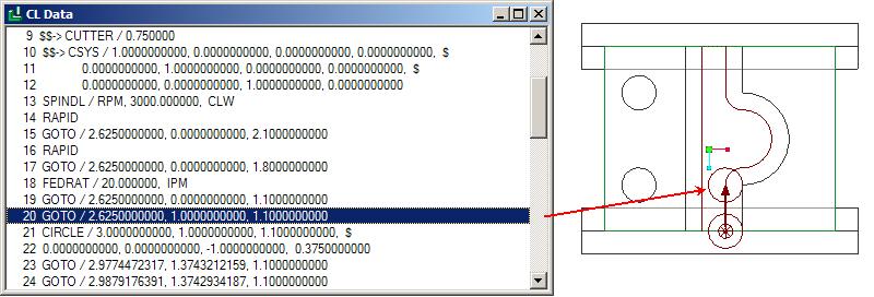

37 Computer-Assisted Part Programming by Pro/Manufacturing > CL Data
38 APT (Automatically Programmed Tool) More than 100 part-programming languages have been developed since 1956 and some have stood the test of time and did not. APT has been the most popular part-programming language and employed by most CAM systems. Summary characteristics of APT is given below Three dimensional unbounded surfaces and points are defined to represent the part Surfaces are defined in a X-Y-Z coordinate system chosen by the part programmer In programming, the tool does all the moving; the part is stationary The tool path is controlled by pairs of three-dimensional surfaces; other motions, not controlled by surfaces, are also possible A series of short straight-line motions are calculated to represent curved tool paths (linear interpolation) The tool path is calculated so as to be within specified tolerances of the controlling surfaces The X, Y, and Z coordinates of successive tool-end positions along the desired tool path are recorded as the general solution to the programming problem Additional processing (postprocessing) of the tool-end coordinates generates the exact tape codes and format for a particular machine
39 An APT processor interprets and computes the cutter path, whereas a post-processor translates the cutter-path to a format acceptable by a specific machine. 1. Identification statements. These define a specific project. 2. Geometry statements. These define a scaler or geometric quantity. 3. Motion statements. These describe a cutter path, such as GOLFT. 4. Postprocessor statements. These define machining parameters such as feed, speed, coolant on/off and so on. 5. Auxiliary statements. These describe auxiliary machine-tool functions to identify the tool, part, tolerances, and so on.
40 ANSI INCITS Programming Language APT (revision, redesignation and consolidation of ANSI X , ANSI X /AM , ANSI X /AM ) (formerly ANSI INCITS ) Establishes the form for, and the interpretation of,programs expressed in the Automatically Programmed Tools (APT) language and of the System-Neutral CLFILE (SCL), which can be generated by processors, such as APT, or by graphical systems. The purpose is to promote portability of these input language programs to a wide variety of computers. In addition, the SCL permits commonality and portability, regardless of the source that produces it, to a wide variety of manufacturing equipment. APT is an English-like language for describing operations for numerically controlled machines. An APT language input program is converted by a computer processor and, probably, subsequently by a postprocessor into an ordered set of instructions for numerically controlled machines.


41 APT: Part Definition (Geometry) Geometry Statements Creating entities such as points, lines, circles, planes, cylinders, cones, and spheres structure variable = function name / function description
 PT=POINT/CENTER,CIRCLE PT=POINT/MODIFIER,INTOF,LINE,CONE (intersection of a line with a cone) PT=POINT/INTOF,PLANE1,PLANE2,PLANE3(intersection of three planes")
42 Point Definitions PT=POINT/X,Y,Z PT=POINT/INTOF,LINE1,LINE2 PT=POINT/MODIFIER,INTOF,LINE1,CIRCLE1 where Modifier options are {xlarge,xsmall,ylarge,ysmall} PT=POINT/MODIFIER,INTOF,C1,C2 PT=POINT/CIRCLE,ATANGL (in degrees) PT=POINT/CENTER,CIRCLE PT=POINT/MODIFIER,INTOF,LINE,CONE (intersection of a line with a cone) PT=POINT/INTOF,PLANE1,PLANE2,PLANE3(intersection of three planes PT=POINT/RTHETA,XYPLAN,RADIUS,ANGLE (polar coordinates) PT=POINT/INTOF,LINE,TABCYL,TABC1 (Intersection of a line and a tabulated cylinder) PT=POINT/PATTERN,N (Point as Nth location of a pattern)
43 Line Definitions Ln=Line/x1,y1,z1,x2.y2.z2 (Line thru a pt and tangent to a circle) Ln=Line/point,modifier,tanto,circle (Line tangent to two circles) Ln=Line/modifier,tanto,circle1, modifier,tanto,circle2 (Line tangent to two circles) Ln=Line/point,atangl,axis (Line thru a pt and making an angle w/axis ) Ln=Line/point,slope,value(Line thru a pt and having a slope ) Ln=Line/xaxis (or yaxis) (Line on a axis) Ln=Line/point,slope,value,line2(Line thru a pt and having a slope wrt another line) Ln=Line/point,parlel,line(Line thru a pt and parallel to another line) Ln=Line/point,perpto,line(Line thru a pt and perpendicular to another line) Ln=Line/parlel,line,modifier,offset value(line parellel to another line given offset distance)
 Ln=Line/point,perpto,tabcyl (Line thru a pt and perpendicular to a tabulated")
44 Ln=Line/intof,plane1,plane2 (Line given by intersection of two planes) Ln=Line/atangl,value,interc,modifier,value Ln=Line/point,tanto,tabcyl (Line in x-y plane passing thru a pt and tangent to a tabulated cylinder) Ln=Line/point,perpto,tabcyl (Line thru a pt and perpendicular to a tabulated cylinder)

45 Ex.3 (programming for geometry) Introduce a coordinate and label geometric entities and define the geometries that can form the part. Define all points and then lines using the points defined before.
46 Planes Definitions Plane requires three points for complete definition. Plane by equation: PL=plane/a,b,c,d in equation ax+by+cz-d=0 Plane by 3 pts: PL=plane/pt1,pt2,pt3 Plane thru a pt and parallel to another plane: PL=plane/pt,parlel,pl2 Plane parallel to another plane at a distance: PL=parlel,pl2,modifier,value, modifier={xsmall,xlarge,ysmall,ylarge,zsmall,zlarge} Plane thru a point and perpendicular to a vector: PL=plane/pt,perpto,vector1 Plane thru two pts and perpendicular to another plane: PL=plane/pt1,pt2,perpto,pl1 Plane perpendicular to two planes and thru a pt: PL=plane/pt,perpto,pl1,pl2
47 Definition of Circle By a center and a radius: C=circle/center,pt1,radius,value By a center and tangent to a line: C=circle/center,pt,tanto,line By a center and a pt on its circumference: C=circle/center,pt1,pt2 on circumference By three pts: C=circle/pt1,pt2,pt3 By a center and a tangent to another circle: C=circle/center,pt1,modifier (large or small) By a radius and two intersecting lines: C=circle/tanto,line,modifier,pt,radius,value By a radius tangent to a line and thru a pt: C=circle/tanto,line,modifier,pt,radius,value By a radius tangent to a line and another circle: C=circle/ modifier,line, modifier,in/out,c2,radius,value By a radius and tangent to two circles: C=circle/ modifier,in/out,c2,in/out,c3,radius,value By a radius tangent to a line and a tabulated cylinder: C=circle/tanto,line1,modifier,tabcyl, modifier,point (closest pt), radius, value
![Definition of Cylinders cy=cylinder/x,y,z,a,b,c,radius cy=cylinder/center_pt,axix_vector,radius tc=tabcyl/modifier1,modifer2,[trform,m],data where](/docs-images/82/87018126/images/48-3.jpg "modifiere={nox,noy,noz,rtheta,thetar} and tabulated cylinder is a surface created by a curve and a vector Suf=rldsuf/suf1,p1,p2,p3,suf2,p4,p5,p6 A ruled surface is")
48 Definition of Cylinders cy=cylinder/x,y,z,a,b,c,radius cy=cylinder/center_pt,axix_vector,radius tc=tabcyl/modifier1,modifer2,[trform,m],data where modifiere={nox,noy,noz,rtheta,thetar} and tabulated cylinder is a surface created by a curve and a vector Suf=rldsuf/suf1,p1,p2,p3,suf2,p4,p5,p6 A ruled surface is created blending two curves.

49 Ex.4 (cylinder) Introduce a coordinate and label geometric entities and define the geometries that can form the part. Start with lines if possible to define entities.

50 Ex.5 (surfaces) Introduce a coordinate and label geometric entities and define the geometries that can form the part. Start with lines if possible to define entities.


51 Additional Definitions Elips = ellipse/center,pt,semi-major axix length, semi-minor axis length, semi-major axis angle. Hyp = hyperb/center, pt, length of half transverse axis, angle of transverse axis Cn = cone/x,y,z,a,b,c,angle where x,y,z and a,b,c are vertex and base center coordinates Cn = cone/point,vector,angle Vc = vector/ x, y, z Vc = vector/pt1,pt2 Vc = vector/perpto,plane,modifier where modifier = {posx,posyposz} Vc = vector/vec1,cross,vec2 Ptrn = pattern/linear,pt1,pt2,no_of_pts Ptrn = pattern/linear,pt,vec,incr,no_of_incr,at,d Ptrn = pattern/linear,pt,vec,incr1,incr2,incr3,,incrn Ptrn = pattern/radial,incr_angle,total_angle,ccw,n

52 Ex.6 (part) Introduce a coordinate and label geometric entities and define the geometries that can form the part. Start with lines if possible to define entities.

53 Motion Statement Basic motion statements are based on three surfaces that guide the tool in three-dimensional space. They are Drive Surface Part Surface Check Surface
54 There are two types of motion; point-to-point (PTP) motion for rapid traversing without cutting contouring for continuous material removal in three-dimensional space.
55 GOTO and FROM Statement GOTO / a point This is a PTP statement for rapid motion. FROM / a point This is to start a motion from.

56 GO Statement This is for contouring. TO TO TO GO / ON, Drive Surface, ON, Part Surface, ON, Check Surface PAST PAST PAST TANTO The modifier TANTO is only used by check surface. CS CS CS DS DS DS DS CS On PS On PS On PS On PS GO/TO,DS,TO,PS,TO,CS GO/TO,DS,TO,PS,ON,CS GO/TO,DS,TO,PS,PAST,CS GO/TO,DS,TO,PS,TANTO,CS
57 Ex.7 Example [Part Program] Make an APT program for the following part with tool compensation using APT. Use POINT, LINE, CIRCLE to define geometry first, and then use motion statements such as FROM, GOTO, GO. Starting point is SP from which move to the point A and then move counterclockwise. At the end of cutting move the tool to the starting point. Ignore all other commands. The point A is located at (1,1) and SP is at the origin. The cutting precision of machine is 1/1000 in. Assume the tool moves tangent to the part surface PL1 that is positioned at z = 0.
58 Solution SP = POINT / 0,0,0 PTA = POINT / 1,1,0 PTB = POINT / 3.8,1,0 PTC = PONT / 3.8,1.735,0 PTD = POINT / 2.815,2.8,0 PTE = POINT / 2.2,2.8,0 PTF = POINT /2.2,2.6,0 PTG = POINT / 1,2.6,0 LNAB = LINE / PTA,PTB LNBC = LINE / PTB,PTC CIRCLECD = CIRCLE / POINT(4.1,3.2,0),PTB,PTC LNDE = LINE / PTD,PTE LNEF = LINE / PTE,PTF LNFG = LINE / PTF,PTG LNGA = LINE / PTG,PTA FROM / SP GO / TO,LNAB,TO,PL1,ON,LNAG GO / TO,LNAB,TO,PL1,PAST,LNBC GO / TO,LNBC,TO,PL1,PAST,CIRCLECD GO / TO,CIRCLECD,TO,PL1,PAST,LNDE GO / TO,LNDE,TO,PL1,PAST,LNEF GO / TO,LNEF,TO,PL1,TO,LNFG GO / TO,LNFG,TO,PL1,PAST,LNGA GO / TO,LNGA,TO,PL1,ON,LNAB GOTO / SP
59 Relative Motion Statement Point-To-Point (PTP) Motion GODLTA / coordinate increment Contouring Motion COMMAND / (TO) Drive Surface, TO/ON/PAST/TANTO, Check Surface Here, the command can be any one of the followings GOLFT GORGT GOUP GODOWN GOFWD GOBACK move left along the drive surface move right along the drive surface move up along the drive surface move down along the drive surface move forward from a tangent position move backward from a tangent position

60 Ex.8 Example. Assuming all geometric entities have been defined as shown in the figure and the hypothetical part plane is PL1, make a possible APT motion program to cut the part.
61 Solution. FROM / START GO / TO,L1,TO,PL1,ON,L3 GORGT / L1,TANTO,C1 GOFWD / C1,TANTO,L2 GOFWD / L2,PAST,L3 GOLEFT / L3,PAST,L1 GOTO / START Note: GOLFT and GORGT for next motion are relative to the direction of the current motion.
62 Miscellaneous Statements Macro is a set of instruction that can be repeatedly used. (i.e., subroutine in Fortran or function in C language) Ex. DRILL = MACRO GODLTA/0,0,-0.5 GODLTA/0,0,+0.5 TERMAC Looping can be programmed just like any other structured programming using LOOPST and LOOPND. PATTERN command defines a set of points and CYCLE command can perform manufacturing operations at those points Ex. Suppose a pattern of points has been defined in PTN2. Then, CYCLE/DRILL(, list of parameters) GOTO/PTN2 CYCLE/OFF
63 Ex.9 The following program shows how to drill holes in a certain pattern. RESERVE/PNT,6 LOOPST STARTY=3 (2,4) J=1 (2,3) (4,3) 4 I =1 STARTX=2 y 5 PNT(I)=POINT/STARTX,STARTY,1 (1,2) IF(I-3) 6,8,8 Hole depths are 0.5 x 6 I = I + 1 STARTX = STARTX + 2 JUMPTO/5 8 IF(J-2) 9,10,10 9 J = J + 1 STARTY = STARTY + 1 JUMPTO/4 10 LOOPND

64 Ex.10 Motion Commands for Milling The following part is to be machined by milling. The work piece is 4 x 5 x 1.6 inches and low-carbon steel. Assume the milling machine is 3-axis CNC.
65 Process Plan: 1.Set the lower left corner of the part as the machine zero-point. 2.Clamp the work piece in a vise. 3.Mill the slot with a ½ in four-flute flat end mill made of carbide. From the Machinability Data Handbook, the recommended feed is in/tooth/rev and recommended cutting speed is 100 fpm 4.Drill four holes with a 0.5-in-diameter twist drill. Use 0.18 ipr feed and 100 fpm speed.
66 Machining Specifications Despite the great deal of standardization through programming languages like APT and computer-assisted part programs, these standards are not so apparent in hardware as in software. As a result, the APT program has to be post-processed for a particular machine. Typical post-processor commands include: MACHIN/ calls a machine tool COOLNT/ coolant fluid can be turned on and off. FEDRAT/ feed rate is specified SPINDL/ spindle speed is specified TURRET/ call a specific tool from tool changer END forces to stop the machine so that the operator can change a tool manually or inspect the part.
67 Tolerance Setting Nonlinear motion along a curve is achieved by a set of continuous straight line segments. The tolerance statements dictate how many line segments to be generated for contouring motion. Either one or both may be specified. OUTTOL / INTOL / 0.001
68 CL Data to MCD CAD/CAM system effectively creates geometry (i.e., modeling) adds PMI (product manufacturing information) produces engineering drawings produces CL data in tool-path simulation by CAP programming like APT helps to convert CL data to machine control data (MCD) for machining in post-processing. MCD = NC control codes
ADVANCED TECHNIQUES APPENDIX A
 A P CONTENTS þ Anilam þ Bridgeport þ Fanuc þ Yasnac þ Haas þ Fadal þ Okuma P E N D I X A ADVANCED TECHNIQUES APPENDIX A - 1 APPENDIX A - 2 ADVANCED TECHNIQUES ANILAM CODES The following is a list of Machinist
P0 = POINT/1.0, 1.2, 1.3 specifies a point at XYZ coordinates 1.0, 1.2, and 1.3, respectively.
 HAND OUT 02: APT PROGRAMMING NOTES APT stands for Automatically Programmed Tool. It is a language that defines the tool path with respect to the part geometry, and often forms the basis for post-processor
Lesson 4 Introduction To Programming Words
 Lesson 4 Introduction To Programming Words All CNC words include a letter address and a numerical value. The letter address identifies the word type. The numerical value (number) specifies the value of
Mach4 CNC Controller Mill Programming Guide Version 1.1 Build 3775
 Mach4 CNC Controller Mill Programming Guide Version 1.1 Build 3775 Copyright 2014 Newfangled Solutions, Artsoft USA, All Rights Reserved The following are registered trademarks of Microsoft Corporation:
CHAPTER 12. CNC Program Codes. Miscellaneous CNC Program Symbols. D - Tool Diameter Offset Number. E - Select Work Coordinate System.
 General CHAPTER 12 CNC Program Codes The next three chapters contain a description of the CNC program codes and parameters supported by the M-Series Control. The M-Series Control has some G codes and parameters
Mach4 CNC Controller Mill Programming Guide Version 1.0
 Mach4 CNC Controller Mill Programming Guide Version 1.0 1 Copyright 2014 Newfangled Solutions, Artsoft USA, All Rights Reserved The following are registered trademarks of Microsoft Corporation: Microsoft,
Conversational Programming for 6000M, 5000M CNC
 Conversational Programming for 6000M, 5000M CNC www.anilam.com P/N 70000486F - Contents Section 1 - Introduction Section 2 - Conversational Mode Programming Hot Keys Programming Hot Keys... 2-1 Editing
Manufacturing Processes with the Aid of CAD/CAM Systems AMEM 405
 AMEM 405 slide 1 Manufacturing Processes with the Aid of CAD/CAM Systems AMEM 405 Dr. Sotiris Omirou AMEM 405 slide 2 CONTENTS 1. CAD/CAM definition 2. Review of Milling Process 3. Know The CNC Machine
HAAS AUTOMATION, INC.
 PROGRAMMING WORKBOOK HAAS AUTOMATION, INC. 2800 Sturgis Rd. Oxnard, CA 93030 JUNE 1, 2000 JUNE 2000 PROGRAMMING CONTENTS INTRODUCTION... 1 THE COORDINATE SYSTEM... 2 MACHINE HOME... 5 ABSOLUTE AND INCREMENTAL
2. INTRODUCTION TO CNC
 Q. Define NC Machines. 2. INTRODUCTION TO CNC A method of automation, in which various functions and processing of machine tools are controlled by letters and symbols. The general objective of NC technology
CNC PART PROGRAMMING
 CNC PART PROGRAMMING (1) Programming fundamentals Machining involves an important aspect of relative movement between cutting tool and workpiece. In machine tools this is accomplished by either moving
Conversational Programming for 6000i CNC
 Conversational Programming for 6000i CNC www.anilam.com P/N 634 755-22 - Contents Section 1 - Introduction Section 2 - Conversational Mode Programming Hot Keys Programming Hot Keys... 2-1 Editing Keys...
Mach4 CNC Controller Lathe Programming Guide Version 1.0
 Mach4 CNC Controller Lathe Programming Guide Version 1.0 1 Copyright 2014 Newfangled Solutions, Artsoft USA, All Rights Reserved The following are registered trademarks of Microsoft Corporation: Microsoft,
G & M Code REFERENCE MANUAL. Specializing in CNC Automation and Motion Control
 REFERENCE MANUAL Specializing in CNC Automation and Motion Control 2 P a g e 11/8/16 R0163 This manual covers definition and use of G & M codes. Formatting Overview: Menus, options, icons, fields, and
Polar coordinate interpolation function G12.1
 Polar coordinate interpolation function G12.1 On a Turning Center that is equipped with a rotary axis (C-axis), interpolation between the linear axis X and the rotary axis C is possible by use of the G12.1-function.
CNC Programming Simplified. EZ-Turn / TurnMill Tutorial.
 CNC Programming Simplified EZ-Turn / TurnMill Tutorial www.ezcam.com Copyright Notice This manual describes software that contains published and unpublished works of authorship proprietary to EZCAM Solutions,
Definition of Cutter Motion. Outline APT (II) Rectilinear Motion. Rectilinear Motion (Cont d)
 Rectilinear Motion. Rectilinear Motion (Cont d)") Outline APT (II) Definition of Basic Motions Rectilinear Point-to-point Contouring Motion Control surfaces Starting and termination Roughing and finishing Definition of Cutter Motion It is easier to define
Outline APT (II) Definition of Basic Motions Rectilinear Point-to-point Contouring Motion Control surfaces Starting and termination Roughing and finishing Definition of Cutter Motion It is easier to define
Century Star Turning CNC System. Programming Guide
 Century Star Turning CNC System Programming Guide V3.5 April, 2015 Wuhan Huazhong Numerical Control Co., Ltd 2015 Wuhan Huazhong Numerical Control Co., Ltd Preface Preface Organization of documentation
Brief Introduction to MasterCAM X4
 Brief Introduction to MasterCAM X4 Fall 2013 Meung J Kim, Ph.D., Professor Department of Mechanical Engineering College of Engineering and Engineering Technology Northern Illinois University DeKalb, IL
ACR-MotionMax Programmer's Reference Manual
 ACR-MotionMax Programmer's Reference Manual Programmer's Reference Manual Programming Information - 1 User Information ACR Series products are used to control electrical and mechanical components of motion
CNC Programming Simplified. EZ-Turn Tutorial.
 CNC Programming Simplified EZ-Turn Tutorial www.ezcam.com Copyright Notice This manual describes software that contains published and unpublished works of authorship proprietary to EZCAM Solutions, Inc.
Section 20: Graphics
 Section 20: Graphics CNC 88HS Graphics Graphics Menu The graphics menu of the page editor has been designed to allow the user to view the part path of the current program in memory. The graphics can be
CIRCULAR INTERPOLATION COMMANDS
 PROGRAMMING JANUARY 2005 CIRCULAR INTERPOLATION COMMANDS G02 CW CIRCULAR INTERPOLATION MOTION & G03 CCW CIRCULAR INTERPOLATION MOTION *X Circular end point X-axis motion *Y Circular end point Y-axis motion
COPYCAT NEW FANGLED SOLUTIONS 2/6/2009
 1.0 INTRODUCTION 1.1 CopyCat is a unique wizard used with MACH3. It is not a stand alone program. This wizard will allow you to jog a machine around and create a Gcode file from the movement. 2.0 REQUIREMENTS
CNC C6/C64/C64T PROGRAMMING MANUAL (LATHE TYPE) BNP-B2264D(ENG)
 BNP-B2264D(ENG)") CNC C6/C64/C64T PROGRAMMING MANUAL (LATHE TYPE) BNP-B2264D(ENG) MELDAS is a registered trademark of Mitsubishi Electric Corporation. Other company and product names that appear in this manual are trademarks
CNC C6/C64/C64T PROGRAMMING MANUAL (LATHE TYPE) BNP-B2264D(ENG) MELDAS is a registered trademark of Mitsubishi Electric Corporation. Other company and product names that appear in this manual are trademarks
MANUFACTURING PROCESSES
 MANUFACTURING PROCESSES - AMEM 201 Lecture 7: CNC MACHINE TOOLS 1 CNC MACHINE TOOLS TERMINOLOGY NC Numerical Control CNC Computer Numerical Control CAD Computer Aided Design CAM Computer Aided Manufacturing
PC-BASED NUMERIC CONTROLLER
 Ncstudio PC-BASED NUMERIC CONTROLLER PROGRAMMING MANUAL there is WEIHONG Where there is motion control Thank you for choosing our products! This manual will help you acquaint with our products and learn
COMPUTER NUMERICAL CONTROL OF MACHINE TOOLS
 COMPUTER NUMERICAL CONTROL OF MACHINE TOOLS Department of Mechanical Engineering and Aeronautics University of Patras, Greece Dr. Dimitris Mourtzis Associate professor Patras, 2017 1/52 Chapter 8: Two
Chapter 1 Introduction to Numerically Controlled Machines
 Chapter 1 Introduction to Numerically Controlled Machines The primary building blocks of flexible manufacturing and computer integrated manufacturing systems are numerically controlled (CNC) machine tools.
What s new in EZCAM Version 18
 CAD/CAM w w w. e z c a m. com What s new in EZCAM Version 18 MILL: New Curve Machining Wizard A new Curve Machining Wizard accessible from the Machining menu automates the machining of common part features
Conversational Programming for 6000M, 5000M CNC
 Conversational Programming for 6000M, 5000M CNC www.anilam.com P/N 70000486E - Warranty Warranty ANILAM warrants its products to be free from defects in material and workmanship for one (1) year from date
TOOLPATHS TRAINING GUIDE. Sample. Distribution. not for MILL-LESSON-4-TOOLPATHS DRILL AND CONTOUR
 TOOLPATHS TRAINING GUIDE MILL-LESSON-4-TOOLPATHS DRILL AND CONTOUR Mill-Lesson-4 Objectives You will generate a toolpath to machine the part on a CNC vertical milling machine. This lesson covers the following
3000M CNC Programming and Operations Manual for Two-Axis Systems
 3000M CNC Programming and Operations Manual for Two-Axis Systems www.anilam.com P/N 70000496G - Contents Section 1 - CNC Programming Concepts Programs... 1-1 Axis Descriptions... 1-1 X Axis... 1-2 Y Axis...
Southwestern Industries, Inc. DPM RX7 Bed Mill Specifications with the ProtoTRAK RMX Control
 Southwestern Industries, Inc. DPM RX7 Bed Mill Specifications with the ProtoTRAK RMX Control Machine Specifications Table size 76 x 14 T-slots (number x width x pitch) 3 x 16mm x 63.5mm Travel (X, Y, Z
Introduction to MasterCAM X4,7
 Introduction to MasterCAM X4,7 Spring 2014 By Meung J. Kim, Ph.D., Professor Department of Mechanical Engineering Northern Illinois University 1 Preliminaries C-Plane: flat Construction plane that can
Conversational Programming for 6000i CNC
 Conversational Programming for 6000i CNC January 2008 Ve 01 634755-21 1/2008 VPS Printed in USA Subject to change without notice www.anilam.com P/N 634755-21 - Warranty Warranty ANILAM warrants its products
NcStudio Programming Manual
 NcStudio Programming Manual 6th Edition Weihong Electronic Technology Co., Ltd. The copyright of this manual belongs to Weihong Electronic Technology Co., Ltd. (hereinafter referred to as Weihong Company).
Mach4 Lathe G-Code and M-Code Reference
 Mach4 Lathe G-Code and M-Code Reference Chapter 1: Introduction G-Code is a special programming language that is interpreted by Computer Numerical Control (CNC) machines to create motion and other tasks.
Introduction to Word Address Programming
 Chapter 1 Introduction to Word Address Programming 1.1 Objectives After completion of this chapter the reader will be able to: 1. Understand the meaning of common terminology associated with writing a
EML 2322L -- MAE Design and Manufacturing Laboratory. CNC Machining
 EML 2322L -- MAE Design and Manufacturing Laboratory CNC Machining Intro to CNC Machining CNC stands for computer numeric controlled. It refers to any machine tool (i.e. mill, lathe, drill press, etc.)
Turning ISO Dialect T
 SINUMERIK 802D Short Guide 09.2001 Edition Turning ISO Dialect T User Documentation SINUMERIK 802D Turning ISO Dialect T Short Guide 09.2001 Edition Valid for Control Software Version SINUMERIK 802D 1
Mach3. Mach3 Gcode Manual Ultimate Screen Reference Guide
 Mach3 Mach3 Gcode Manual Ultimate Screen Reference Guide Mach3 Gcode Manual 1 Definitions 1.1 Linear Axes The X, Y, and Z axes form a standard right-handed coordinate system of orthogonal linear axes.
Part Programming Manual MACHINEMATE
 MACHINEMATE NOTE Progress is an ongoing commitment at MACHINEMATE INC. We continually strive to offer the most advanced products in the industry. Therefore, information in this document is subject to change
Prototext 4. Why use Prototext 4
 Prototext 4 Prototext is a simple & affordable windows based program for custom engraving used with 2 & 3 axis CNC milling machines. Prototext has been used by machinists for over 15 years. Up till now
Section 15: Touch Probes
 Touch Probes Touch Probe - Length Offset The tool setting probe is used with the UTILITY command to establish the length offset. It can also be used for tool breakage detection and setting tool diameter
GE FANUC 21 CONCEPT 55 MILL ATC TEACHER GUIDE
 GE FANUC 21 CONCEPT 55 MILL ATC TEACHER GUIDE 11/1/07 Version 2 Made by EMCO Authored by Chad Hawk Training Index Control Keyboard Pg 1 Fanuc 21 Control Machine Control Fanuc 21 Screen. Pg 2 Fanuc 21 Keys.
ISO INTERNATIONAL STANDARD
 INTERNATIONAL STANDARD ISO 6983-1 Second edition 2009-12-15 Automation systems and integration Numerical control of machines Program format and definitions of address words Part 1: Data format for positioning,
Programming Features PERFORMANCE & SPECIFICATIONS
 PERFORMANCE & SPECIFICATIONS Essentials Processor Intel Pentium Instruction Set 32-bit Performance Number of Cores 1 Processor Base Frequency 1.8 GHz Memory Data Storage 1 GB System Memory Installed 2
GE Fanuc Automation. Series 15 / 150 Model B for Machining Center. Computer Numerical Control Products. Descriptions Manual
 GE Fanuc Automation Computer Numerical Control Products Series 15 / 150 Model B for Machining Center Descriptions Manual GFZ-62082E/04 April 1997 Warnings, Cautions, and Notes as Used in this Publication
CNC 8055 MC EXAMPLES MANUAL REF Ref. 0601
 EXAMPLES MANUAL Ref. 0601 All rights reserved. No part of this documentation may be copied, transcribed, stored in a data backup system or translated into any language without Fagor Automation's explicit
Industrial Automation (Automação de Processos Industriais)
") Industrial Automation (Automação de Processos Industriais) http://users.isr.ist.utl.pt/~jag/courses/api1213/api1213.html Slides 2010/2011 Prof. Paulo Jorge Oliveira Rev. 2011-2013 Prof. José Gaspar Page
Industrial Automation (Automação de Processos Industriais) http://users.isr.ist.utl.pt/~jag/courses/api1213/api1213.html Slides 2010/2011 Prof. Paulo Jorge Oliveira Rev. 2011-2013 Prof. José Gaspar Page
Prismatic Machining Overview What's New Getting Started User Tasks
 Prismatic Machining Overview Conventions What's New Getting Started Enter the Workbench Create a Pocketing Operation Replay the Toolpath Create a Profile Contouring Operation Create a Drilling Operation
ADT-CNC4940 CNC4940 Milling Machine Control System. Programming Manual
 ADT-CNC4940 CNC4940 Milling Machine Control System Programming Manual Adtech (Shenzhen) Technology Co., Ltd. Add: F/5, Bldg/27-29, Tianxia IC Industrial Park, Yiyuan Rd, Nanshan District, Shenzhen Postal
Industrial Automation (Automação de Processos Industriais)
") MEEC 2011-2012 Industrial Automation (Automação de Processos Industriais) http://users.isr.ist.utl.pt/~jag/courses/api1112/api1112.html Slides 2010/2011 Prof. Paulo Jorge Oliveira Rev. 2011/2012 Prof.
MEEC 2011-2012 Industrial Automation (Automação de Processos Industriais) http://users.isr.ist.utl.pt/~jag/courses/api1112/api1112.html Slides 2010/2011 Prof. Paulo Jorge Oliveira Rev. 2011/2012 Prof.
2D AUTOCAD GEOMETRIC DATA EXTRACTION AND POST- PROCESSING FOR NUMERICAL CONTROL
 2D AUTOCAD GEOMETRIC DATA EXTRACTION AND POST- PROCESSING FOR NUMERICAL CONTROL Tito E. Mwinuka* and Beda M. Mutagahywa ** Department of Mechanical and Industrial Engineering, University of Dar es Salaam,
3300M/MK CNC Programming and Operations Manual
 3300M/MK CNC Programming and Operations Manual www.anilam.com P/N 70000381C - Contents Section 1 - CNC Programming Concepts Programs... 1-1 Axis Descriptions... 1-1 X Axis... 1-2 Y Axis... 1-2 Z Axis...
Table of Contents. Table Of Contents. Access to parameters (lesson 2)) 26 Surprised? 26 Key Points for Lesson 1: 26 Quiz 26
) 26 Surprised? 26 Key Points for Lesson 1: 26 Quiz 26") Preface 9 Why you should buy this book 9 What is parametric programming? 10 A word about CAM systems 10 Scope 10 Versions of Custom Macro 10 Machine types 10 Prerequisites 11 Optional status 11 Lessons
Preface 9 Why you should buy this book 9 What is parametric programming? 10 A word about CAM systems 10 Scope 10 Versions of Custom Macro 10 Machine types 10 Prerequisites 11 Optional status 11 Lessons
SimplyCam V3. Documentation
 SimplyCam V3. Documentation Introduction to SimplyCam SimplyCam is a simple Cad/Cam system that creates toolpaths (G-Code). The geometric part can be created internally, with the available tools or imported
Our thanks go to: Puppy Linux, RTAI, EMC, axis, all the kernel developers and big mama thornton.
 CoolCNC Linux First Steps This manual is a step by step introduction for the installation of the CoolCNC Linux Live CD. Its intent is to lead to a better understanding of the current processes. This document
 PROGRAMMING WORKBOOK HAAS AUTOMATION, INC 2800 Sturgis Rd Oxnard, CA 93030 January 2004 JANUARY 2004 PROGRAMMING HAAS AUTOMATION INC 2800 Sturgis Road Oxnard, California 93030 Phone: 805-278-1800 www
4.10 INVOLUTE INTERPOLATION (G02.2, G03.2)
") B 63014EN/02 POGAMMNG 4. NTEPOLATON FUNCTONS 4.10 NVOLUTE NTEPOLATON (G02.2, G03.2) nvolute curve machining can be performed by using involute interpolation. nvolute interpolation ensures continuous pulse
B 63014EN/02 POGAMMNG 4. NTEPOLATON FUNCTONS 4.10 NVOLUTE NTEPOLATON (G02.2, G03.2) nvolute curve machining can be performed by using involute interpolation. nvolute interpolation ensures continuous pulse
NC CODE REFERENCE MANUAL
 NC CODE REFERENCE MANUAL Thank you very much for purchasing this product. To ensure correct and safe usage with a full understanding of this product's performance, please be sure to read through this manual
Mill Level 1 Training Tutorial
 To order more books: Call 1-800-529-5517 or Visit www.inhousesolutions.com or Contact your Mastercam dealer Mastercam X 5 Copyright: 1998-2010 In-House Solutions Inc. All rights reserved Software: Mastercam
Warranty. Student Workbook for Three-Axis Systems
 www.anilam.com P/N 70000505 - Warranty Warranty ANILAM warrants its products to be free from defects in material and workmanship for one (1) year from date of installation. At our option, we will repair
VisualCAM 2018 for SOLIDWORKS-TURN Quick Start MecSoft Corporation
 2 Table of Contents Useful Tips 4 What's New 5 Videos & Guides 6 About this Guide 8 About... the TURN Module 8 Using this... Guide 8 Getting Ready 10 Running... VisualCAM for SOLIDWORKS 10 Machining...
Computer Aided Engineering Applications 3. Advanced Manufacturing 3.5 NC programming 3.6 Automated Manufacturing systems 3.7 Rapid prototyping
 Computer Aided Engineering Applications 3. Advanced Manufacturing 3.5 NC programming 3.6 Automated Manufacturing systems 3.7 Rapid prototyping Engi 6928 - Fall 2014 3.5 Part programming Structure of an
MAX CONTROL FOR TURNING CENTERS
 MAX CONTROL FOR TURNING CENTERS Preliminary NC Programming Manual March 2005 PRE 704-0115-301, B Revision B The information in this document is subject to change without notice and does not represent a
FAGOR AUTOMATION MC TRAINING MANUAL
 FAGOR AUTOMATION MC TRAINING MANUAL ACER MC TRAINING MANUAL 8 holes 1/2" depth grid pattern R0.125 1.5 6 unit: inch R0.25 4 1.25 2 2.675 1/2" depth rectangular pocket 1/2" depth circular pocket R0.75 8
Series 0ί -MD Mate CNC STANDARD FEATURES
 STANDARD FEATURES Axis Control Digital Servo Function 1 Controlled Path Simultaneously controlled axes: Up to maximum of 3 Serial Encoder Interface Axis Name Selected from X,Y,Z and U,V,W,A,B,C Spindle
G47 Text Engraving (Group 00) - Mill. Troubleshooting. How it Works. Haas Technical Documentation. Setting 85 is Too High for Shallow Text Engraving
 - Mill. Troubleshooting. How it Works. Haas Technical Documentation. Setting 85 is Too High for Shallow Text Engraving") Haas Technical Documentation G47 Text Engraving (Group 00) - Mill Scan code to get the latest version of this document Translation Available Troubleshooting Setting 85 is Too High for Shallow Text Engraving
Haas Technical Documentation G47 Text Engraving (Group 00) - Mill Scan code to get the latest version of this document Translation Available Troubleshooting Setting 85 is Too High for Shallow Text Engraving
IEEM 215. Manufacturing Processes I Introduction to the ARIX CNC milling machine
 IEEM 215. Manufacturing Processes I Introduction to the ARIX CNC milling machine The image below is our ARIX Milling machine. The machine is controlled by the controller. The control panel has several
Instructions. elucad Software. Version en Translation of the original instructions. Retain for future use.
 Instructions Version 3.0.0 en Translation of the original instructions. Retain for future use. elusoft GmbH Breitwasenring 4 D 72135 Dettenhausen Phone +49(0)7157 526-6500 Fax +49(0)7157 526-6526 info@elusoft.de
Creo 3.0 G-code Tutorial
 Creo 3.0 G-code Tutorial Irobotics µtan(clan) Table of Contents 1. Preface... 2 2. CAD... 3 A. Prepare the CAD... 3 B. Define the Coordinate System... 3 C. Save the CAD... 6 3. Create NC assembly... 6
Coordinate System Techniques
 Coordinate System Techniques In this lesson, we ll show some advanced implications of what can be done with coordinate systems. For the most part, this lesson applies to machining centers. But there are
VERO UK TRAINING MATERIAL. 2D CAM Training
 VERO UK TRAINING MATERIAL 2D CAM Training Vcamtech Co., Ltd 1 INTRODUCTION During this exercise, it is assumed that the user has a basic knowledge of the VISI-Series software. OBJECTIVE This tutorial has
GE FANUC 21 CONCEPT 55 TURN TEACHER GUIDE
 GE FANUC 21 CONCEPT 55 TURN TEACHER GUIDE 2/13/08 Version 2 Made by EMCO Authored by Chad Hawk Training Index Control Keyboard Pg 1 Fanuc 21 Control Machine Control Fanuc 21 Screen Pg 2 Fanuc 21 Keys Pg
9000 CNC 9000 CNC: THE NEW STANDARD OF CONTROL. INTUITIVE EFFICIENT PRODUCTIVE
 3D Solid Model Graphics Solid Model with Tool Path Overlay 9000 CNC 9000 CNC: THE NEW STANDARD OF CONTROL. At Milltronics we are constantly refining our controls to simplify operation, shorten setup times
VisualMILL Getting Started Guide
 VisualMILL Getting Started Guide Welcome to VisualMILL Getting Started Guide... 4 About this Guide... 4 Where to go for more help... 4 Tutorial 1: Machining a Gasket... 5 Introduction... 6 Preparing the
Dolphin 3DCAM Help. Copyright <2018> by <Dolphin Cadcam Systems Ltd>. V All Rights Reserved.
 Copyright by . V1.020216 All Rights Reserved. Table of Contents Introduction... 3 Getting Started... 4 The Ribbon Toolbar... 5 File... 6 Geom... 9 Solids... 24 View...
Copyright 2019 OPEN MIND Technologies AG
 Copyright 2019 OPEN MIND Technologies AG This document applies to hypermill and hypermill SHOP Viewer. It contains notes about recent changes that are not described in the manual. All rights reserved.
Software designed to work seamlessly with your CNC Masters machine. Made to work with Windows PC. Works with standard USB
 Software designed to work seamlessly with your CNC Masters machine Made to work with Windows PC Works with standard USB Clutter free interface. The software is engineered for the machine so you don t have
Geometry Practice. 1. Angles located next to one another sharing a common side are called angles.
 Geometry Practice Name 1. Angles located next to one another sharing a common side are called angles. 2. Planes that meet to form right angles are called planes. 3. Lines that cross are called lines. 4.
itnc 530 NC Software English (en) 8/2006
 8/2006") adp h" itnc 530 NC Software 340 490-03 340 491-03 340 492-03 340 493-03 340 494-03 English (en) 8/2006 The smart.nc Pilot... is your concise programming guide for the new smart.nc operating mode of the
adp h" itnc 530 NC Software 340 490-03 340 491-03 340 492-03 340 493-03 340 494-03 English (en) 8/2006 The smart.nc Pilot... is your concise programming guide for the new smart.nc operating mode of the
Introduction CAUTION. Details described in this manual
 Introduction This manual is a guide for using the MELDAS 60/60S Series, MELDASMAGIC64. Programming is described in this manual, so read this manual thoroughly before starting programming. Thoroughly study
The ProtoTRAK Parasolid Converter Operating Manual
 The ProtoTRAK Parasolid Converter Operating Manual Document: P/N 28070 Version: 042216 Parasolid for Mills Compatible with offline and SMX ProtoTRAK Control models Southwestern Industries, Inc. 2615 Homestead
Multi-Axis Surface Machining
 CATIA V5 Training Foils Multi-Axis Surface Machining Version 5 Release 19 January 2009 EDU_CAT_EN_MMG_FI_V5R19 1 About this course Objectives of the course Upon completion of this course you will be able
NOTE This function is optional.
 5.AUTOMATIC OPERATION B-63943EN-1/03 5.8 RETRACE M Overview The tool can retrace the path along which the tool has moved so far (reverse execution). Furthermore, the tool can move along the retraced path
TRAINING GUIDE MILL-LESSON-FBM-2 FBM MILL AND FBM DRILL
 TRAINING GUIDE MILL-LESSON-FBM-2 FBM MILL AND FBM DRILL Mastercam Training Guide Objectives This lesson will use the same Feature Based Machining (FBM) methods used in Mill-Lesson- FBM-1, how ever this
What's New in CAMWorks 2016
 Contents (Click a link below or use the bookmarks on the left) About this Version (CAMWorks 2016 SP3)... 2 Supported Platforms 2 Resolved CPR s document 2 About this Version (CAMWorks 2016 SP2.2) 3 Supported
EZ-Mill EXPRESS TUTORIAL 2. Release 13.0
 E-Mill EPRESS TUTORIAL 2 Release 13.0 Copyright Notice This manual describes software that contains published and unpublished works of authorship proprietary to ECAM Solutions, Inc. It is made available
KA3-6VS 300mm KA3-6VS 400mm Vertical Spindle
 Vertical KA3-6VS 300mm KA3-6VS 400mm Vertical Spindle The Kira KA3- Series of traveling column (3) Axis CNC Machining Modules are an excellent choice for special application machine builders. These modules
Feature-based CAM software for mills, multi-tasking lathes and wire EDM. Getting Started
 Feature-based CAM software for mills, multi-tasking lathes and wire EDM www.featurecam.com Getting Started FeatureCAM 2015 R3 Getting Started FeatureCAM Copyright 1995-2015 Delcam Ltd. All rights reserved.
CAD/CAM DESIGN TOOLS. Software supplied with all new and upgraded Boxford Lathes, Mills and Routers
 CAD/CAM DESIGN TOOLS Software supplied with all new and upgraded Boxford Lathes, Mills and Routers The Boxford CAD/CAM Design Tools software is a unique suite of integrated CAD and CAM tools designed specifically
Copyright 2018 OPEN MIND Technologies AG
 Release Notes Copyright 2018 OPEN MIND Technologies AG This document applies to hypermill and hypermill SHOP Viewer. It contains notes about recent changes that are not described in the manual. All rights
MULTI-AXIS TURNING CENTER SKT210Y/SY SKT250Y/SY
 MULTI-AXIS TURNING CENTER SKT0Y/SY SKT50Y/SY CNC Turning Center World Top Class Quality HYUNDAI-KIA Machine High Speed, High Accuracy, High Rigidity Speed & Power CNC Turning Center SKT0/50Y/SY SKT0SY
CNC Knee Type Milling Machines with USA CENTROID M-400S CNC control
 CNC Knee Type Milling Machines with USA CENTROID M-400S CNC control GMM-949-CNC, 9 x49 table, R8, vari-speed, 3 axis CNC... GMM-949F-CNC, 9 x49 table, R8, inverter drive, 5,000 rpm, 3 axis CNC.. Note:
TRAINING GUIDE MILL-LESSON-FBM-1 FBM MILL AND FBM DRILL
 TRAINING GUIDE MILL-LESSON-FBM-1 FBM MILL AND FBM DRILL Mastercam Training Guide Objectives Previously in Mill-Lesson-6 and Mill-Lesson-7 geometry was created and machined using standard Mastercam methods.
Dolphin PartMaster Milling
 Dolphin PartMaster Milling Copyright 2000-2017 Dolphin CadCam Systems Ltd.. This document is copyrighted and all rights are reserved. This document may not, in whole or in part, be copied or reproduced
What's New in CAMWorks 2016
 Contents (Click a link below or use the bookmarks on the left) What s New in CAMWorks 2016 SP0 2 Supported Platforms 2 Resolved CPR s document 2 Improved Tool Management Interactions... 3 Tool tree view
Accurate Trajectory Control for Five-Axis Tool-Path Planning
 Accurate Trajectory Control for Five-Axis Tool-Path Planning Rong-Shine Lin* and Cheng-Bing Ye Abstract Computer-Aided Manufacturing technology has been widely used for three-axis CNC machining in industry