NMS USER MANUAL. WAP-EN Series Wireless Access Points. Version 1.2, June 2017
|
|
|
- Verity Sutton
- 6 years ago
- Views:
Transcription

1 NMS USER MANUAL WAP-EN Series Wireless Access Points Version 1.2, June 2017
2 Copyright Copyright 2017 Comtrend Corporation. All rights reserved. The information contained herein is proprietary to Comtrend Corporation. No part of this document may be translated, transcribed, reproduced, in any form, or by any means without the prior written consent of Comtrend Corporation. This program is free software: you can redistribute it and/or modify it under the terms of the GNU General Public License as published by the Free Software Foundation, either version 3 of the License, or (at your option) any later version. This program is distributed in the hope that it will be useful, but WITHOUT ANY WARRANTY; without even the implied warranty of MERCHANTABILITY or FITNESS FOR A PARTICULAR PURPOSE. See the GNU General Public License for more details. You should have received a copy of the GNU General Public License along with this program. If not, see NOTE: This document is subject to change without notice. 2
3 I. Product Information The Network Management Suite (NMS) supports the central management of a group of access points, otherwise known as an AP Array. NMS can be installed on one access point and support up to 5 access points or on a Wireless LAN Controller (WLC) and support up to 50 access points. Access points can be deployed and configured according to your requirements. This flexibility creates a powerful network architecture which can be easily managed and expanded in the future. The easy to use interface and a full range of functionality make the NMS system ideal for small and mid-sized office environments. 3
4 Table of Contents I. Product Information... 3 II. Quick Setup... 7 III. Software Layout IV. Features IV-1. LOGIN, LOGOUT & RESTART IV-2. DASHBOARD IV-2-1. System Information IV-2-2. Devices Information IV-2-3. Managed AP IV-2-4. Managed AP Group IV-2-5. Active Clients IV-2-6. Active Users IV-3. ZONE PLAN IV-4. NMS MONITOR IV-4-1. Access Point IV Managed AP IV Managed AP Group IV-4-2. WLAN IV Active WLAN IV Active WLAN Group IV-4-3. Clients IV Active Clients IV-4-4. Users IV Active Users IV Users Log IV-4-5. Rogue Devices IV-4-6. Information IV All Events/Activities IV AP Monitoring IV SSID Overview IV-5. NMS Settings IV-5-1. Access Point IV-5-2. WLAN IV-5-3. RADIUS IV-5-4. Access Control IV-5-5. Guest Network
5 IV-5-6. Users IV Add/Edit Guest Portal IV Front Desk URL IV Front Desk Printout IV Guest Portal Type IV Guest Portal Customization IV-5-9. Schedule IV Smart Roaming IV Device Monitoring IV Firmware Upgrade IV Advanced IV System Security V Date & Time V System Accounts IV-6. Local Network IV-6-1. Network Settings IV LAN-Side IP Address IV LAN Port Settings IV VLAN IV GHz 11bgn (Not available on the WLC-6404) IV Basic IV Advanced IV Security IV No Authentication IV WEP IV IEEE802.1x/EAP IV WPA-PSK IV WPA-EAP IV Additional Authentication IV WDS IV GHz 11ac 11an (Not available on the WLC-6404) IV Basic IV Advanced IV Security IV WDS IV-6-4. WPS (Not available on the WLC-6404) IV-6-5. RADIUS (Not available on the WLC-6404) IV RADIUS Settings IV Internal Server IV RADIUS Accounts IV-6-6. MAC Filter (Not available on the WLC-6404)
6 IV-6-7. WMM (Not available on the WLC-6404) IV-6-8. Internal Server IV Internal RADIUS Server IV RADIUS Accounts IV-6-9. Schedule IV-7. Local Settings IV-7-1. Operation Mode (Not available on the WLC-6404) IV-7-2. System Settings IV System Information IV Wireless Clients (Not available on the WLC-6404) IV Wireless Monitor (Not available on the WLC-6404) IV Log IV-7-3. Management IV Admin IV Date and Time IV Syslog Server IV I m Here IV-7-4. Advanced IV LED Settings IV Update Firmware IV Save/Restore Settings IV Factory Default IV Reboot IV-8. Toolbox IV-8-1. Network Connectivity IV Ping IV Trace Route V. Best Practice How to Create and Link WLAN & Access Point Groups
7 II. Quick Setup One device is designated as the AP Controller (master) and other connected APs are designated as Managed APs (slaves). Using the NMS you can monitor, configure and manage all Managed APs. Up to 5 APs can be managed from an EN-Series Wireless Access Point in AP Controller Mode or 50 APs can be managed from a dedicated WLC-6404 Wireless Access Point Controller. Follow the steps below: 1. Connect all APs to an Ethernet or PoE switch which is connected to a gateway/router. You can use your router as a DHCP server or you can later configure your AP Controller as a DHCP server. 2. Ensure all APs are powered on and check the LED status. 7

8 3. Connect the AP Controller, which will manage all other connected APs, to power and turn the device on. 4. Connect a computer to the AP Controller using an Ethernet cable. 5. Open a web browser and enter the AP Controller s IP address in the address field. The default IP address is listed in the User Manual for your controller. Typically it is either or DHCP is enabled on the access point by default. Consult the DHCP Table of your network for the Controller s IP Address. If no DHCP Service is found, the access point will default to the default IP address listed in the User Manual. Typical default IP addresses are either or Your computer s IP address must be in the same subnet as the AP Controller is being used in this example. 6. Enter the username & password to login. The default username & password are admin & 1234 respectively. 8

9 7. If using an EN-Series AP as a controller, you will arrive at the Access Point Information screen. Go to! Operation Mode and select AP Controller Mode from the drop down menu to initiate Controller Mode. 8. Click Apply to save the settings. 9. Your Controller AP & Managed APs should be fully functional. Use the top menu to navigate around the NMS. Use Local Network & Local Settings to configure your Controller AP. Use Dashboard, Zone Plan, NMS Monitor & NMS Settings to configure Managed APs. Use Toolbox to diagnose connection issues. 9

10 III. Software Layout The top menu features 7 panels: Dashboard, Zone Plan, NMS Monitor, NMS Settings, Local Network, Local Settings & Toolbox. Screenshots displayed are examples. The information shown on your screen will vary depending on your configuration and device being used as a controller. Dashboard The Dashboard panel displays an overview of your network and key system information, with quick links to access configuration options for Managed APs and Managed AP groups. Each panel can be refreshed, collapsed or moved according to your preference. (Available settings will vary depending on the device being used as an AP Controller.) 10


11 Zone Plan Zone Plan displays a customizable live map of Managed APs for a visual representation of your network coverage. Each AP icon can be moved around the map, and a background image can be uploaded for user-defined location profiles using NMS Settings! Zone Edit. Options can be configured using the menu on the right side and signal strength is displayed for each AP. (Available settings will vary depending on the device being used as an AP Controller.) NMS Monitor The NMS Monitor panel provides more detailed monitoring information about the AP Array than found on the Dashboard, grouped according to categories in the menu down the left side. (Available settings will vary depending on the device being used as an AP Controller.) 11

 Local Network Local Network settings are for your AP Controller. You can configure the IP address and DHCP server of the AP Controller in addition to 2.")
12 NMS Settings NMS Settings provides extensive configuration options for the AP Array. You can manage each access point, assign access points into groups, manage WLAN, RADIUS as well as upgrade firmware across multiple access points. The Zone Plan can also be configured using Zone Edit. (Available settings will vary depending on the device being used as an AP Controller.) Local Network Local Network settings are for your AP Controller. You can configure the IP address and DHCP server of the AP Controller in addition to 2.4GHz & 5Ghz Wi-Fi and security, with WPS, RADIUS server, MAC filtering and WMM settings 12
13 also available. (Available settings will vary depending on the device being used as an AP Controller.) Local Settings Local Settings are for your AP Controller. You can set the operation mode and view network settings (clients and logs) specifically for the AP Controller, as well as other management settings such as date/time, admin accounts, firmware and reset. (Available settings will vary depending on the device being used as an AP Controller.) 13

14 Toolbox The Toolbox panel provides a network diagnostic tools: ping and trace route. 14
15 IV. Features Descriptions of the functions of each main panel Dashboard, Zone Plan, NMS Monitor, NMS Settings, Local Network, Local Settings & Toolbox can be found below. (Available settings will vary depending on the device being used as an AP Controller.) When using the NMS, click Apply to save changes: Screenshots displayed are examples. The information shown on your screen will vary depending on your configuration. IV-1. LOGIN, LOGOUT & RESTART LOGIN It is recommended that you login to the AP Controller to make configuration changes to Managed APs. 1. Connect a computer to the designated AP Controller using an Ethernet cable: 2. Open a web browser and enter the AP Controller s IP address in the address field. The default IP address is listed in the User Manual for your controller. Typically it is either or Your computer s IP address must be in the same subnet as the AP Controller. Refer to V-1. Configuring your IP Address for more help. DHCP is enabled on the access point by default. Consult the DHCP Table of your network for the Controller s IP Address. If no DHCP Service is found, the access point will default to the default IP address listed in the User Manual. Typical default IP addresses are either or

16 If using a DHCP server on the network, it is advised to use your DHCP server s settings to assign the AP Controller a static IP address. 3. Enter the username & password to login. The default username & password are admin & RESTART You can restart your AP Controller or any Managed AP using the NMS. To restart your AP Controller go to Local Settings! Advanced! Reboot and click Reboot. To restart Managed APs click the Restart icon for the specified AP on the Dashboard: 16

17 IV-2. DASHBOARD The dashboard displays an overview of your AP array: Use the blue icons above to refresh or collapse each panel in the dashboard. Click and drag to move a panel to suit your preference. You can set the dashboard to auto-refresh every 1 minute, 30 seconds or disable auto-refresh: 17


18 IV-2-1. System Information System Information displays information about the AP Controller: Product Name (model), Host Name, MAC Address, IP Address, Firmware Version, System Time, Uptime, CPU Usage and Memory Usage. IV-2-2. Devices Information Devices Information is a summary of the number of all devices in the local network: Access Points, Clients Connected, and Rogue (unidentified) Devices. 18
19 IV-2-3. Managed AP Managed AP displays information about each Managed AP in the local network: Index (reference number), MAC Address, Device Name, Model, IP Address, 2.4GHz & 5GHz Wireless Channel Number, No. of Clients connected to each access point, and Status (connected, connecting or disconnected). The search function can be used to locate a specific Managed AP. Type in the search box and the list will update: The Status icon displays grey (disconnected), yellow (connecting) or green (connected) for each Managed AP. Each Managed AP has Action icons with the following functions: 1. Disallow Remove the Managed AP from the AP array and disable connectivity. 2. Edit Edit various settings for the Managed AP (refer to IV-5-1. Access Point). 3. Blink LED The Managed AP s LED will flash temporarily to help identify & locate access points. 4. Buzzer The Managed AP s buzzer will sound temporarily to help identify & locate access points. 5. Network Connectivity Go to the Network Connectivity panel to perform a ping or traceroute. 6. Restart Restarts the Managed AP. 19
20 IV-2-4. Managed AP Group Managed APs can be grouped according to your requirements. Managed AP Group displays information about each Managed AP group in the local network: Group Name, MAC Address, Device Name, Model, IP Address, No. of Clients connected to each access point, and Status (connected or disconnected). To edit Managed AP Groups go to NMS Settings! Access Point (refer to IV-5-1. Access Point). The search function can be used to locate a specific Managed AP Group. Type in the search box and the list will update: The Status icon displays grey (disconnected), yellow (connecting) or green (connected) for each individual Managed AP. Each Managed AP has Action icons with the following functions: 1. Disallow Remove the Managed AP from the AP array and disable connectivity. 2. Edit Edit various settings for the Managed AP (refer to IV-5-1. Access Point) 3. Blink LED The Managed AP s LED will flash temporarily to help identify & locate access points. 4. Buzzer The Managed AP s buzzer will sound temporarily to help identify & locate access points. 5. Network Connectivity Go to the Network Connectivity panel to perform a ping or traceroute. 20
21 6. Restart Restarts the Managed AP. IV-2-5. Active Clients Active Clients displays information about each client in the local network: Index (reference number), Client MAC Address, Device Name, Model, IP Address, 2.4GHz & 5GHz Wireless Channel Number, No. of Clients connected to each access point, and Status (on or off). The search function can be used to locate a specific client. Type in the search box and the list will update: IV-2-6. Active Users Active Users displays information about each user in the local network: Index (reference number), User Name, MAC Address, IP Address, SSID, Creator, Creation Time, Expire Time, Usage Percentage, Vendor, Platform and Action. The search function can be used to locate a specific user. Type in the search box and the list will update: 21
 to create a visual map of your AP array. Use the menu on the side to make adjustments and mouse-over an AP icon in the zone map to see more information.")

22 IV-3. ZONE PLAN The Zone Plan can be fully customized to match your network environment. You can move the AP icons and select different location images (upload location images in NMS Settings! Zone Edit) to create a visual map of your AP array. Use the menu on the side to make adjustments and mouse-over an AP icon in the zone map to see more information. Click an AP icon in the zone map to select it and display action icons. Click and drag an AP icon to move the icon around the zone map. The signal strength for each AP is displayed according to the Signal key in the menu on the right side: Location Select a pre-defined location from the drop down menu. When you upload a location image in NMS Settings! Zone Edit, it will be available for selection here. 22
23 AP Group Search Radio Signal Zoom Transparency Scale Device/Number You can select an AP Group to display in the zone map. Edit AP Groups in NMS Settings! Access Point. Use the search box to quickly locate an AP. Use the checkboxes to display APs according to 2.4GHz or 5GHz wireless radio frequency. Signal strength key for the signal strength display around each AP in the zone map. Use the slider to adjust the zoom level of the map. Use the slider to adjust the transparency of location images. Zone map scale. Displays number and type of devices in the zone map. 23
24 IV-4. NMS MONITOR IV-4-1. Access Point IV Managed AP Displays information about each Managed AP in the local network: Index (reference number), MAC Address, Device Name, Model, IP Address, 2.4GHz & 5GHz Wireless Channel Number, No. of Clients connected to each access point, and Status (connected, connecting or disconnected). The search function can be used to locate a specific Managed AP. Type in the search box and the list will update: The Status icon displays the status of each Managed AP. Status Icons Icon Color Status Definition Grey Red Disconnected Authentication Failed Or Incompatible NMS Version Managed AP is disconnected. Check the network connection and ensure the Managed AP is in the same IP subnet as the AP Controller. System security must be the same for all access points in the AP array. Please check security settings (refer to IV System Security). Access points must use the same version of NMS as the Controller. Use the AP Controller s firmware upgrade function (refer to IV Firmware Upgrade) to synchronize the NMS version. 24
25 Orange Configuring or Upgrading Managed AP is making configuration changes or upgrading the firmware. Yellow Connecting Managed AP is connecting. Green Connected Managed AP is connected. Blue Waiting for Approval Managed AP is waiting for approval. Each Managed AP has Action icons with the following functions: 1. Disallow Remove the Managed AP from the AP array and disable connectivity. 1. Edit Edit various settings for the Managed AP (refer to IV-5-1. Access Point). 2. Blink LED The Managed AP s LED will flash temporarily to help identify & locate access points. 3. Buzzer The Managed AP s buzzer will sound temporarily to help identify & locate access points. 4. Network Connectivity Go to the Network Connectivity panel to perform a ping or traceroute. 5. Restart Restarts the Managed AP. 25


26 IV Managed AP Group Managed APs can be grouped according to your requirements. Managed AP Group displays information about each Managed AP group in the local network: Group Name, MAC Address, Device Name, Model, IP Address, 2.4GHz & 5GHz Wireless Channel Number, No. of Clients connected to each access point, and Status (connected or disconnected). To edit Managed AP Groups go to NMS Settings! Access Point (refer to IV-5-1. Access Point). The search function can be used to locate a specific Managed AP Group. Type in the search box and the list will update: The Status icon displays grey (disconnected), red (authentication failed/incompatible NMS version), orange (upgrading firmware), yellow (connecting), green (connected) or blue (waiting for approval) for each individual Managed AP. Refer to IV Managed AP: Status Icons for full descriptions. Each Managed AP has Action icons with the following functions: 2. Disallow Remove the Managed AP from the AP array and disable connectivity. 26
27 3. Edit Edit various settings for the Managed AP (refer to IV-5-1. Access Point). 4. Blink LED The Managed AP s LED will flash temporarily to help identify & locate access points. 5. Buzzer The Managed AP s buzzer will sound temporarily to help identify & locate access points. 6. Network Connectivity Go to the Network Connectivity panel to perform a ping or traceroute. 7. Restart Restarts the Managed AP. 27
, Name/SSID, VLAN ID, Authentication, Encryption, IP Address and Additional Authentication.")
28 IV-4-2. WLAN IV Active WLAN Displays information about each SSID in the AP Array: Index (reference number), Name/SSID, VLAN ID, Authentication, Encryption, IP Address and Additional Authentication. To configure encryption and VLANs for Managed APs go to NMS Settings! WLAN. The search function can be used to locate a specific SSID. Type in the search box and the list will update: 28

29 IV Active WLAN Group WLAN groups can be created according to your preference. Active WLAN Group displays information about WLAN group: Group Name, Name/SSID, VLAN ID, Authentication, Encryption, IP Address and Additional Authentication. The search function can be used to locate a specific Active WLAN Group. Type in the search box and the list will update: IV-4-3. Clients IV Active Clients Displays information about clients currently connected to the AP Array: Index(reference number),client MAC Address, AP MAC Address, WLAN (SSID), User Name, Radio (2.4GHz or 5GHz), Signal Strength received by Client, Connected Time, Idle Time, Tx & Rx (Data transmitted and received by Client in KB), and the Vendor of the client device. You can set or disable the auto-refresh time for the client list or click Refresh to manually refresh. The search function can be used to locate a specific client. Type in the search box and the list will update: 29
, User Name, MAC Address, IP Address, SSID, Creator, Create Time, Expire Time,")
30 IV-4-4. IV Users Active Users Displays information about each user in the local network via guest portals: Index (reference number), User Name, MAC Address, IP Address, SSID, Creator, Create Time, Expire Time, Usage Percentage, Traffic Progress, Vendor and Platform of the user device. The search function can be used to locate a specific client. Type in the search box and the list will update: IV Users Log Displays a detailed information log of users and activity on the network via guest portals: ID, Date and Time of entry, Category of entry, Severity, Users, Event/Activities details. The search function can be used to locate a specific client. Type in the search box and the list will update: 30
, Channel, SSID, MAC Address, Security,")
31 IV-4-5. Rogue Devices Rogue access point detection can identify any unauthorized access points which may have been installed in the network. Click Start to scan for rogue devices: Unknown Rogue Devices displays information about rogue devices discovered during the scan: Index (reference number), Channel, SSID, MAC Address, Security, Signal Strength, Type, Vendor and Action. The search function can be used to locate a known rogue device. Type in the search box and the list will update: 31
, Traffic Rx (data received in MB), No.")
32 IV-4-6. Information IV All Events/Activities Displays a log of time-stamped events for each access point in the Array use the drop down menu to select an access point and view the log. IV AP Monitoring Displays graphical monitoring information about access points in the Array for 2.4GHz & 5GHz: Traffic Tx (data transmitted in MB), Traffic Rx (data received in MB), No. of Clients, Wireless Channel, Tx Power (wireless radio power), CPU Usage and Memory Usage. Use the drop down menus to select an access point and date. You can set or disable the auto-refresh time for the data: 32
33 IV SSID Overview Displays graphical monitoring information about different SSIDs for 2.4GHz & 5GHz, including Traffic Tx (data transmitted in Kbps), Traffic Rx (data received in Kbps), and also the Client Number for each SSID. You can use Refresh to run the manual refresh: 2.4GHz & 5GHz Traffic shows currently how much Tx/Rx traffic (in KBps) utilized in each SSID. The blue diagram represents the 2.4GHz radio band, and the green diagram represents the 5GHz radio band. 33
34 Client Number shows currently how many current users on each SSID. The blue diagram represents the 2.4GHz radio band, and the green diagram represents the 5GHz radio band. 34

35 IV-5. NMS Settings IV-5-1. Access Point Displays information about each access point and access point group in the local network and allows you to edit access points and edit or add access point groups. The search function can be used to locate an access point or access point group. Type in the search box and the list will update: The Status icon displays grey (disconnected), red (authentication failed/incompatible NMS version), orange (upgrading firmware), yellow (connecting), green (connected) or blue (waiting for approval) for each individual Managed AP. Refer to IV Managed AP: Status Icons for full descriptions. The Action icons enable you to allow or disallow an access point: Select an access point or access point group using the check-boxes and click Edit to make configurations, or click Add to add a new access point group: 35
36 The Access Point Settings panel can enable or disable Auto Approve for all Managed APs. When enabled, Managed APs will automatically join the AP Array with the Controller AP. When disabled, Managed APs must be manually approved to join the AP Array with the Controller AP. Access Point Settings Auto Approve Enable or disable Auto Approve for all Managed APs. To manually approve a Managed AP, use the allow Action icon for the specified access point: Edit Access Point Configure your selected access point on your LAN. You can set the access point as a DHCP client or specify a static IP address for your access point, and assign the access point to an AP group, as well as edit 2.4GHz & 5GHz wireless radio settings. An events log is displayed at the bottom of the page. You can also use Profile Settings to assign the access point to WLAN, RADIUS and Access Control groups independently from Access Point Group settings. Check the Override Group Settings box to use different individual settings for access points assigned to AP Groups: 36

37 Basic Settings Name Description MAC Address AP Group IP Address Assignment IP Address Subnet Mask Edit the access point name. The default name is AP + MAC address. Enter a description of the access point for reference e.g. 2 nd Floor Office. Displays MAC address. Use the drop down menu to assign the AP to an AP Group. You can edit AP Groups from the NMS Settings! Access Point page. Select DHCP Client for your access point to be assigned a dynamic IP address from your router s DHCP server, or select Static IP to manually specify a static/fixed IP address for your access point (below). Check the box Override Group Setting if the AP is a member of an AP Group and you wish to use a different setting than the AP Group setting. Specify the IP address here. This IP address will be assigned to your access point and will replace the default IP address. Specify a subnet mask. The default value is 37

38 Default Gateway Primary DNS Secondary DNS For DHCP users, select From DHCP to get default gateway from your DHCP server or User-Defined to enter a gateway manually. For static IP users, the default value is blank. DHCP users can select From DHCP to get primary DNS server s IP address from DHCP or User-Defined to manually enter a value. For static IP users, the default value is blank. DHCP users can select From DHCP to get secondary DNS server s IP address from DHCP or User-Defined to manually enter a value. For static IP users, the default value is blank. Radio Settings Wireless Band Enable or disable the access point s 2.4GHz or 5GHz wireless radio. When disabled, no SSIDs on that frequency will be active. Select the wireless standard used for the access point. Combinations of b, 38
39 Auto Pilot Auto Pilot Range Auto Pilot Interval Channel Bandwidth BSS BasicRateSet g, n & ac can be selected. Enable/disable auto channel selection. Auto channel selection will automatically set the wireless channel for the access point s 2.4GHz or 5GHz frequency based on availability and potential interference. When disabled, select a channel manually. Select a range from which the auto channel setting (above) will choose a channel. Specify a frequency for how often the auto channel setting will check/reassign the wireless channel. Check/uncheck the Change channel even if clients are connected box according to your preference. Set the channel bandwidth or use Auto (automatically select based on interference level). Set a Basic Service Set (BSS) rate: this is a series of rates to control communication frames for wireless clients. These settings are for experienced users only. Please do not change any of the values on this page unless you are already familiar with these functions. Changing these settings can adversely affect the performance of your access point. Advanced Settings Contention Slot Preamble Type Select Short or Long this value is used for contention windows in WMM (see IV-6-7. WMM). Set the wireless radio preamble type. The preamble type in based wireless communication defines the length of the CRC (Cyclic Redundancy Check) block for communication between the access point and roaming wireless adapters. The default value is Short Preamble. Guard Interval Set the guard interval. A shorter interval can improve performance. 39
 to access point, and access point will broadcast Clear to Send (CTS), before a packet is")
40 802.11g Protection Enable/disable g protection, which increases reliability but reduces bandwidth (clients will send Request to Send (RTS) to access point, and access point will broadcast Clear to Send (CTS), before a packet is sent from client.) n Protection Enable/disable n protection, which increases reliability but reduces bandwidth (clients will send Request to Send (RTS) to access point, and access point will broadcast Clear to Send (CTS), before a packet is sent from client.) DTIM Period Set the DTIM (delivery traffic indication message) period value of the wireless radio. The default value is 1. RTS Threshold Set the RTS threshold of the wireless radio. The default value is Fragment Set the fragment threshold of the wireless Threshold radio. The default value is Multicast Rate Set the transfer rate for multicast packets or use the Auto setting. Tx Power Set the power output of the wireless radio. You may not require 100% output power. Setting a lower power output can enhance security since potentially malicious/unknown users in distant areas will not be able to access your signal. Beacon Interval Set the beacon interval of the wireless radio. Station idle timeout The default value is 100. Set the interval for keep alive messages from the access point to a wireless client to verify if the station is still alive/active. 40
41 Profile Settings WLAN Group RADIUS Group Access Control Group Assign the access point s 2.4GHz or 5GHz SSID(s) to a WLAN Group. You can edit WLAN groups in NMS Settings! WLAN. Assign the access point s 2.4GHz SSID(s) to a RADIUS group. You can edit RADIUS groups in NMS Settings! RADIUS. Assign the access point s 2.4GHz SSID(s) to a RADIUS group. You can edit RADIUS groups in NMS Settings! Access Control Add/Edit Access Point Group Configure your selected access point group. Access point group settings apply to all access points in the group, unless individually set to override group settings. You can use Profile Group Settings to assign the access point group to WLAN, RADIUS and Access Control groups. The Group Settings panel can be used to quickly move access points between existing groups: select an access point and use the drop down menu or search to select access point groups and use << and >> arrows to move APs between groups. Basic Group Settings Name Description Edit the access point group name. Enter a description of the access point group for reference e.g. 2 nd Floor Office Group. 41

42 Radio Group Settings Wireless Band Auto Pilot Auto Pilot Range Auto Pilot Interval Channel Bandwidth Enable or disable the access point group s 2.4GHz or 5GHz wireless radio. When disabled, no SSIDs on that frequency will be active. Select the wireless standard used for the access point group. Combinations of b, g, n & ac can be selected. Enable/disable auto channel selection. Auto channel selection will automatically set the wireless channel for the access point group s 2.4GHz or 5GHz frequency based on availability and potential interference. When disabled, select a channel manually. Select a range from which the auto channel setting (above) will choose a channel. Specify a frequency for how often the auto channel setting will check/reassign the wireless channel. Check/uncheck the Change channel even if clients are connected box according to your preference. Set the channel bandwidth or use Auto 42
43 BSS BasicRateSet (automatically select based on interference level). Set a Basic Service Set (BSS) rate: this is a series of rates to control communication frames for wireless clients. These settings are for experienced users only. Please do not change any of the values on this page unless you are already familiar with these functions. Changing these settings can adversely affect the performance of your access points. Advanced Settings Contention Slot Preamble Type Select Short or Long this value is used for contention windows in WMM (see IV-6-7. WMM). Set the wireless radio preamble type. The preamble type in based wireless communication defines the length of the CRC (Cyclic Redundancy Check) block for communication between the access point and roaming wireless adapters. The default value is Short Preamble. Guard Interval Set the guard interval. A shorter interval can improve performance g Protection Enable/disable g protection, which increases reliability but reduces bandwidth (clients will send Request to Send (RTS) to access point, and access point will broadcast Clear to Send (CTS), before a packet is sent from client.) n Protection Enable/disable n protection, which increases reliability but reduces bandwidth (clients will send Request to Send (RTS) to access point, and access point will broadcast Clear to Send (CTS), before a packet is sent from client.) DTIM Period Set the DTIM (delivery traffic indication message) period value of the wireless radio. The default value is 1. 43

44 RTS Threshold Fragment Threshold Multicast Rate Tx Power Beacon Interval Station idle timeout Set the RTS threshold of the wireless radio. The default value is Set the fragment threshold of the wireless radio. The default value is Set the transfer rate for multicast packets or use the Auto setting. Set the power output of the wireless radio. You may not require 100% output power. Setting a lower power output can enhance security since potentially malicious/unknown users in distant areas will not be able to access your signal. Set the beacon interval of the wireless radio. The default value is 100. Set the interval for keep alive messages from the access point to a wireless client to verify if the station is still alive/active. Profile Group Settings WLAN Group Assign the access point group s 2.4GHz or 44
45 RADIUS Group Access Control Group 5GHz SSIDs to a WLAN Group. You can edit WLAN groups in NMS Settings! WLAN. Assign the access point group s 2.4GHz SSIDs to a RADIUS group. You can edit RADIUS groups in NMS Settings! RADIUS. Assign the access point s 2.4GHz SSIDs to a RADIUS group. You can edit RADIUS groups in NMS Settings! Access Control. 45

46 IV-5-2. WLAN Displays information about each WLAN and WLAN group in the local network and allows you to add or edit WLANs & WLAN Groups. When you add a WLAN Group, it will be available for selection in NMS Settings! Access Point access point Profile Settings & access point group Profile Group Settings. The search function can be used to locate a WLAN or WLAN Group. Type in the search box and the list will update: Select a WLAN or WLAN Group using the check-boxes and click Edit or click Add to add a new WLAN or WLAN Group: 46
47 Add/Edit WLAN WLAN Settings Name/ESSID Description SSID VLAN ID Broadcast SSID Wireless Client Isolation Edit the WLAN name (SSID). Enter a description of the SSID for reference e.g. 2 nd Floor Office HR. Select which SSID to configure security settings for. Specify the VLAN ID. Enable or disable SSID broadcast. When enabled, the SSID will be visible to clients as an available Wi-Fi network. When disabled, the SSID will not be visible as an available Wi-Fi network to clients clients must manually enter the SSID in order to connect. A hidden (disabled) SSID is typically more secure than a visible (enabled) SSID. Enable or disable wireless client isolation. Wireless client isolation prevents clients connected to the access point from communicating with each other and improves security. Typically, this function is useful for corporate environments or public hot spots 47
48 Load Balancing Authentication Method Additional Authentication and can prevent brute force attacks on clients usernames and passwords. Load balancing limits the number of wireless clients connected to an SSID. Set a load balancing value (maximum 50). Select an authentication method from the drop down menu. Select an additional authentication method from the drop down menu. Various security options (wireless data encryption) are available. When data is encrypted, information transmitted wirelessly cannot be read by anyone who does not know the correct encryption key. It s essential to configure wireless security in order to prevent unauthorised access to your network. Select hard-to-guess passwords which include combinations of numbers, letters and symbols, and change your password regularly. Please refer to IV Security for more information on authentication and additional authentication types. WLAN Advanced Settings RSSI Threshold Set a RSSI Threshold level. 48

49 Add/Edit WLAN Group When you add a WLAN Group, it will be available for selection in NMS Settings! Access Point access point Profile Settings& access point group Profile Group Settings. WLAN Group Settings Name Edit the WLAN Group name. Description Enter a description of the WLAN Group for reference e.g. 2 nd Floor Office HR Group. Members Select SSIDs to include in the group using the checkboxes and assign VLAN IDs. 49

50 IV-5-3. RADIUS Displays information about External & Internal RADIUS Servers, Accounts and Groups and allows you to add or edit RADIUS Servers, Accounts & Groups. When you add a RADIUS Group, it will be available for selection in NMS Settings! Access Point access point Profile Settings& access point group Profile Group Settings. The search function can be used to locate a RADIUS Server, Account or Group. Type in the search box and the list will update: Make a selection using the check-boxes and click Edit or click Add to add a new WLAN or WLAN Group: 50
51 Add/Edit External RADIUS Server Name Description RADIUS Server Enter a name for the RADIUS Server. Enter a description of the RADIUS Server for reference. Enter the RADIUS server host IP address. Authentication Port Set the UDP port used in the authentication protocol of the RADIUS server. Value must be between Shared Secret Enter a shared secret/password between 1 99 characters in length. This should match the MAC-RADIUS password. Session Timeout Accounting Set a duration of session timeout in seconds between Enable or disable RADIUS accounting. Accounting Port When accounting is enabled (above), set the UDP port used in the accounting protocol of the RADIUS server. Value must be between
52 Add/Edit Internal RADIUS Server Upload EAP Certificate File EAP Certificate File Format EAP Certificate File Displays the EAP certificate file format: PCK#12(*.pfx/*.p12) Click Upload to open a new window and select the location of an EAP certificate file to use. If no certificate file is uploaded, the internal RADIUS server will use a self-made certificate. Internal RADIUS Server Name Description EAP Certificate File Format EAP Certificate File Enter a name for the Internal RADIUS Server. Enter a description of the Internal RADIUS Server for reference. Displays the EAP certificate file format: PCK#12(*.pfx/*.p12) Click Upload to open a new window and select the location of an EAP certificate file to use. If no certificate file is uploaded, the internal RADIUS server will use a self-made certificate. 52
53 EAP Internal Authentication Shared Secret Session Timeout Select EAP internal authentication type from the drop down menu. Enter a shared secret/password for use between the internal RADIUS server and RADIUS client. The shared secret should be 1 99 characters in length. Set a duration of session timeout in seconds between Termination Action Select a termination-action attribute: Reauthentication sends a RADIUS request to the access point, Not-Reathentication sends a default termination-action attribute to the access point, Not-Send no termination-action attribute is sent to the access point. Add/Edit RADIUS Accounts The internal RADIUS server can authenticate up to 256 user accounts. The RADIUS Accounts page allows you to configure and manage users. 53
54 RADIUS Accounts User Name Add Reset Enter the user names here, separated by commas. Click Add to add the user to the user registration list. Clear text from the user name box. User Registration List Select Check the box to select a user. User Name Displays the user name. Password Displays if specified user name has a password (configured) or not (not configured). Customize Click Edit to open a new field to set/edit a password for the specified user name (below). Delete Selected Delete All Delete selected user from the user registration list. Delete all users from the user registration list. Edit User Registration List User Name Existing user name is displayed here and can be edited according to your preference. Password Enter or edit a password for the specified user. 54

55 Add/Edit RADIUS Group When you add a RADIUS Group, it will be available for selection in NMS Settings! Access Point access point Profile Settings & access point group Profile Group Settings. RADIUS Group Settings Group Name Edit the RADIUS Group name. Description Enter a description of the RADIUS Group for reference. 2.4GHz RADIUS Enable/Disable primary & secondary RADIUS servers for 2.4GHz. 5GHz RADIUS Enable/Disable primary & secondary RADIUS servers for 5GHz. Members Add RADIUS user accounts to the RADIUS group (Maximum 5). 55

56 IV-5-4. Access Control MAC Access Control is a security feature that can help to prevent unauthorized users from connecting to your access point. This function allows you to define a list of network devices permitted to connect to the access point. Devices are each identified by their unique MAC address. If a device which is not on the list of permitted MAC addresses attempts to connect to the access point, it will be denied. The Access Control panel displays information about MAC Access Control & MAC Access Control Groups and Groups and allows you to add or edit MAC Access Control & MAC Access Control Group settings. When you add an Access Control Group, it will be available for selection in NMS Settings! Access Point access point Profile Settings& access point group Profile Group Settings. The search function can be used to locate a MAC address or MAC Access Control Group. Type in the search box and the list will update: Make a selection using the check-boxes and click Edit or click Add to add a new MAC Address or MAC Access Control Group: 56
57 Add/Edit MAC Access Control Add MAC Address Add Reset Enter a MAC address of computer or network device manually e.g. aa-bb-cc-dd-ee-ff or enter multiple MAC addresses separated with commas, e.g. aa-bb-cc-dd-ee-ff,aa-bb-cc-dd-ee-gg Click Add to add the MAC address to the MAC address filtering table. Clear all fields. MAC address entries will be listed in the MAC Address Filtering Table. Select an entry using the Select checkbox. Select MAC Address Delete Selected Delete All Export Delete selected or all entries from the table. The MAC address is listed here. Delete the selected MAC address from the list. Delete all entries from the MAC address filtering table. Click Export to save a copy of the MAC filtering table. A new window will pop up for you to select a location to save the file. 57

58 Add/Edit MAC Access Control Group When you add an Access Control Group, it will be available for selection in NMS Settings! Access Point access point Profile Settings& access point group Profile Group Settings. MAC Filter Group Settings Group Name Edit the MAC Access Control Group name. Description Enter a description of the MAC Access Control Group for reference. Action Select Blacklist to deny access to specified MAC addresses in the group, and select Whitelist to permit access to specified MAC address in the group. Members Add MAC addresses to the group. 58
59 IV-5-5. Guest Network You can setup an additional Guest Wi-Fi network so guest users can enjoy Wi-Fi connectivity without accessing your primary networks. The Guest screen displays settings for your guest Wi-Fi network. The Guest Network panel displays information about Guest Networks and Guest Network Groups and allows you to add or edit Guest Network and Guest Network Group settings. When you add a Guest Network Group, it will be available for selection in NMS Settings! Access Point access point Profile Settings & access point group Profile Group Settings. The search function can be used to locate a Guest Network or Guest Network Group. Type in the search box and the list will update: Make a selection using the check-boxes and click Edit or click Add to add a new Guest Network or Guest Network Group. 59

60 Add/Edit Guest Network Guest Network Settings Name/ESSID Edit the Guest Network name (SSID). Description Enter a description of the Guest Network for reference e.g. 2 nd Floor Office HR. VLAN ID Specify the VLAN ID. Broadcast SSID Enable or disable SSID broadcast. When enabled, the SSID will be visible to clients as an available Wi-Fi network. When disabled, the SSID will not be visible as an available Wi-Fi network to clients clients must manually enter the SSID in order to connect. A hidden (disabled) SSID is typically more secure than a visible (enabled) SSID. Wireless Client Enable or disable wireless client isolation. 60
61 Isolation Load Balancing Authentication Method Additional Authentication Wireless client isolation prevents clients connected to the access point from communicating with each other and improves security. Typically, this function is useful for corporate environments or public hot spots and can prevent brute force attacks on clients usernames and passwords. Load balancing limits the number of wireless clients connected to an SSID. Set a load balancing value (maximum 50). Select an authentication method from the drop down menu. Select an additional authentication method from the drop down menu. Various security options (wireless data encryption) are available. When data is encrypted, information transmitted wirelessly cannot be read by anyone who does not know the correct encryption key. It s essential to configure wireless security in order to prevent unauthorised access to your network. Select hard-to-guess passwords which include combinations of numbers, letters and symbols, and change your password regularly. Guest Access Policy Guest Portal Traffic Shaping Downlink Uplink IP Filtering Rules Select a guest portal to use for this guest SSID. Guest portals can be configured in NMS Settings! Guest Portal. Enable or disable traffic shaping for the guest network. Enter a downlink limit in MB. Enter an uplink limit in MB. Select Deny or Allow to deny or allow specified IP addresses to access the guest network. Select Disable to disable IP filtering. Enter IP addresses to be filtered according to 61
 Add/Edit Guest Network Group When you add a Guest Network Group, it will be available for selection in NMS Settings!")
62 the Deny or Allow rule specified above and check the box for each IP address to be filtered. Guest Network Advanced Settings Schedule Group Assign guest SSID to a specified schedule (schedule must be pre-configured in NMS Settings! Schedule.) Add/Edit Guest Network Group When you add a Guest Network Group, it will be available for selection in NMS Settings! Access Point access point Profile Settings & access point group Profile Group Settings. Guest Network Group Settings Group Name Edit the Guest Network Group name. Description Enter a description of the Guest Network for reference. Members Add SSIDs to the Guest Network group. You can override individual VLAN ID & schedule settings and assign a different VLAN ID or schedule. IV-5-6. Users User accounts can be created, monitored and managed for use with the controller s guest portal function. Guest portal settings can be found at IV-5-7. Guest Portal (NMS Settings! Guest Portal). 62

63 When a guest portal is enabled, users who connect to the Guest SSID will automatically arrive at the customizable guest portal page. From there a user account login is required to access the network. These user accounts are created and grouped here, and then selected as the Authentication User Group at NMS Settings! Guest Portal. The guest portal also generates a Front Desk URL which allows staff/admins to login and quickly create/manage user accounts and expiry times, and generate & print tickets with login credentials to give to guest users. These staff/admin accounts are created and grouped here, and selected as the Front Desk User Group at NMS Settings! Guest Portal. Information on the Users page is displayed about each user account and user account group. The search function can be used to locate a user or user group. Type in the search box and the list will update: The Status icon displays grey (logged out), yellow (expired), red (locked) or green (active) for each user. The Action icons can lock/unlock or revive (an expired) user account. Select a user or user group using the check-boxes and click Edit to make configurations, or click Add to add new users and groups: 63


64 Add/Edit User User Settings Name Description Password Confirm Password User Group Edit the user account name. Enter a description of the user account name e.g. Guest Portal 1 Specify a password for the account. Confirm the password for the account. Assign the user account to a user group so it can be utilized by the guest portal. Add/Edit User Group User Group Settings Name Description Role Type Members Edit the user group name. Enter a description of the user group name e.g. Front Desk or Guest Users. Select whether the group is for Guest Portal users or Front Desk managers. Select which user accounts to include in the group. 64

65 IV-5-7. Guest Portal Displays information about guest portals and allows you to edit guest portal settings. Guest portals require users to be created at NMS Settings! Users. When a guest portal is enabled, users who connect to the Guest SSID will automatically arrive at the customizable guest portal page. From there a user account login is required to access the network. These user accounts are created and grouped at NMS Settings! Users, and then selected as the Authentication User Group here. The guest portal also generates a Front Desk URL which allows staff/admins to login and quickly create/manage user accounts and expiry times, and generate & print tickets with login credentials to give to guest users. These staff/admin accounts are created and grouped at NMS Settings! Users and then selected as the Front Desk User Group here. Guest Portal Settings Idle Timeout Login Password Retry Lockout Specify a duration of idle time after which the guest portal will timeout. Specify number of incorrect login attempts before the user account is locked. 65
66 IV Add/Edit Guest Portal Add a guest portal or edit an existing guest portal for use with the guest network. Guest Portal Settings Name Description Guest Portal Type Authentication Server Front Desk User Group Front Desk Generation URL Front Desk Printout Message Authentication User Group Landing Page Edit the name of the guest portal for reference. Enter a description of the guest portal for reference. Select a guest portal type. Refer below for more information about available types. Select an authentication server: Local Database is the default setting. Select a user group for front desk access. Displays the URL of your Front Desk page. See below for more information. Edit the content of Front Desk printout ticket. Refer below for more information. Select a user group for login to the guest network. Specify a landing page for users after successful login. 66

. 2.")
67 IV Front Desk URL Go to this URL in a web browser and members of the Front Desk User Group can login to create guest accounts, set expiry limits and printout tickets. Guest Portal Type Dynamic must be selected to use Front Desk. 1. Login with an account from the Front Desk User Group (NMS Settings! Users). 2. The Guest Account Wizard allows you to setup a new user account and configure the valid period & SSID, or upload a bulk guest list in.csv format. Click Next to continue. 67

 accounts.")

68 3. A summary of the new account(s) is displayed with quick links to print tickets for individual or all new accounts. 4. The Guest Account Monitor displays all guest accounts along with status and quick action icons to print, revive expired accounts or lock/unlock (disable/enable) accounts. Yellow: Expired Red: Locked Grey: Logged out Green: Active Mouseover a status or action icon for a description, and use the arrows to reorder the list according to S/N or Status. Anytime you choose to print account(s) your browser will open a print dialog box where you can select your print destination and configure print settings as usual: 68

69 IV Front Desk Printout Edit and preview the content of the Front Desk printout in the text box using the variables listed in the Definition Table. E.g. (USERNAME) will display on the printout as the specified username. Guest Portal Type Dynamic must be selected to use Front Desk. 69

70 IV Guest Portal Type Four types of guest portal are available from the drop down menu: Free Service Level Agreement Static Users Dynamic Users Redirects users to the specified landing page, with no user login required. Requires users to accept terms and conditions, with no user login required. Requires user login and accept terms and conditions. Users must be created in NMS at NMS Settings! Users. Front Desk is not used. Requires user login and accept terms and conditions. Allows Front Desk to create user accounts in addition to NMS. 70

71 IV Guest Portal Customization Guest portal customization varies according to guest portal type. Click Edit to make changes. Login Portal Settings Header Image Logo Image Title Message Background Color Terms of Use Select an 800 x 200 header image. Select a 200 x 50 logo image. Enter a title message for the guest portal page. Specify a background color as a HEX value. Enter your terms of use. 71

72 IV-5-8. Zone Edit Zone Edit displays information about zones for use with the Zone Plan feature and allows you to add or edit zones. The search function can be used to find existing zones. Type in the search box and the list will update: Make a selection using the check-boxes and click Edit or click Add to add a new zone. 72
73 Add/Edit Zone Upload Zone Image Choose File Zone Setting Name/Location Description Members Click to locate an image file to be displayed as a map in the Zone Plan feature. Typically a floor plan image is useful. Enter a name of the zone/location. Enter a description of the zone/location for reference. Assign access points to the specified zone/location for use with the Zone Plan feature. 73


74 IV-5-9. Schedule You can define schedules according to day, start time and end time - and group multiple schedules together into schedule groups. Schedule groups can be assigned to WLANs, WLAN Groups & Guest Network at NMS Settings! WLAN and NMS Settings! Guest Network. Add/Edit Schedule Use the checkboxes and drop-down menus to setup your schedule. 74

75 Add/Edit Schedule Group WLAN Group Settings Name Edit the schedule group name. Description Enter a description of the schedule group for reference. Members Select individual schedules to include in the schedule group using the checkboxes. 75


76 IV Smart Roaming Smart Roaming enables you to setup the Roaming groups and the Used WLAN SSID, WAN Group and AP Number. Before setup the roaming group, the WLAN Settings need to be configured first. For example, please click NMS Settings >> WLAN, check 2.4GHz SSID, and then click Edit. Configure k as Enable. Please note, don't configure the Authentication as OPEN. Then click Save and Apply. Please wait about 3 minutes. 76
 Enter 4 characteristics on Mobility Domain.")
 Select WLAN Group, and select WLAN.")
 Click Edit icon on 1st AP.")
77 Roaming Group Setting Procedure: (1) Enter Name of this setting. (2) Enter 4 characteristics on Mobility Domain. (3) Enter 32 characteristics on Encryption Key. (4) Select WLAN Group, and select WLAN. (5) It will display APs using this WLAN Setting. (6) Click Edit icon on 1st AP. (7) Enter 2nd AP MAC Address, click Save and Close. (8) Click Edit icon on 2nd AP. (9) Enter 1st AP MAC Address, click Save and Close. 77

78 Then, click Save and Apply, and wait about 3 minutes. Congratulations, you have configured r and k successfully. IV Device Monitoring Device monitoring enables you to specify and monitor the status any IP devices on the network such as IP cameras. The description and status of each device is displayed in the table. Add or Edit IP devices by entering the IP address. 78

79 IV Firmware Upgrade Firmware Upgrade allows you to upgrade firmware to Access Point Groups. First, upload the firmware file from a local disk or external FTP server: locate the file and click Upload or Check. The table below will display the Firmware Name, Firmware Version, NMS Version, Model and Size. Then click Upgrade All to upgrade all access points in the Array or select Access Point groups from the list using check-boxes and click Upgrade Selected to upgrade only selected access points. 79


80 IV Advanced IV System Security Configure the NMS system name and security key for communication between AP Controller and Managed APs. V Date & Time Configure the date & time settings of the AP Array. The date and time of the access points can be configured manually or can be synchronized with a time server. Date and Time Settings Local Time Set the access point s date and time manually using the drop down menus. Acquire Current Click Acquire Current Time from Your PC to Time from your PC enter the required values automatically according to your computer s current time and date. 80
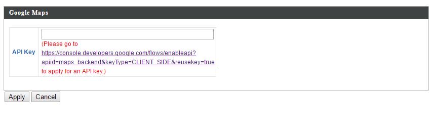
81 NTP Time Server Use NTP Server Name Update Interval Time Zone Time Zone The access point also supports NTP (Network Time Protocol) for automatic time and date setup. Enter the host name or IP address of the time server if you wish. Specify a frequency (in hours) for the access point to update/synchronize with the NTP server. Select the time zone of your country/ region. If your country/region is not listed, please select another country/region whose time zone is the same as yours. V System Accounts Import the API Key which was received Google Developers. This is for the Online Map feature in Zone Plan page. Graphical zone plans with Google Maps integration and setup wizards are available for expanding and managing large networks with multiple access points Note: Please go to d&keytype=client_side&reusekey=true to apply for an API key first to utilize this feature set. 81
82 82

83 IV-6. Local Network IV-6-1. Network Settings IV LAN-Side IP Address The LAN-side IP address page allows you to configure your AP Controller on your Local Area Network (LAN). You can enable the access point to dynamically receive an IP address from your router s DHCP server or you can specify a static IP address for your access point, as well as configure DNS servers. You can also set your AP Controller as a DHCP server to assign IP addresses to other devices on your LAN. LAN-side IP Address IP Address Assignment Static IP Address IP Address Subnet Mask Default Gateway Select Static IP to manually specify a static/fixed IP address for your access point. Select DHCP Client for your access point to be assigned a dynamic IP address from your router s DHCP server, or select DHCP Server for your access point to act as a DHCP server and assign IP addresses on your LAN. Specify the IP address here. This IP address will be assigned to your access point and will replace the default IP address. Specify a subnet mask. The default value is For DHCP users, select From DHCP to get default gateway from your DHCP server or 83

84 Primary DNS Address Secondary DNS Address User-Defined to enter a gateway manually. For static IP users, the default value is blank. For static IP users, the default value is blank. For static IP users, the default value is blank. DHCP Client IP Address Subnet Mask Default Gateway Primary DNS Address Secondary DNS Address When DHCP Client is selected this value cannot be modified. When DHCP Client is selected this value cannot be modified. Select From DHCP or select User-Defined and enter a default gateway. Select From DHCP or select User-Defined and enter a primary DNS address. Select From DHCP or select User-Defined and enter a secondary DNS address. 84

85 DHCP Server IP Address Subnet Mask IP Address Range Domain Name Lease Time Default Gateway Primary DNS Address Secondary DNS Address Specify the IP address here. This IP address will be assigned to your access point and will replace the default IP address. Specify a subnet mask. The default value is Enter the start and end IP address of the IP address range which your access point s DHCP server will assign to devices on the network. Enter a domain name. Select a lease time from the drop down menu. IP addresses will be assigned for this period of time. Enter a default gateway. Enter a primary DNS address. Enter a secondary DNS address. Your access point s DHCP server can be configured to assign static (fixed) IP addresses to specified network devices, identified by their unique MAC address: DHCP Server Static IP Address MAC Address Enter the MAC address of the network device 85
86 IP Address Add to be assigned a static IP address. Specify the IP address to assign the device. Click to assign the IP address to the device. IV LAN Port Settings The LAN Port page allows you to configure the settings for your AP Controllers wired LAN (Ethernet) ports. Wired LAN Port Identifies LAN port 1 or 2. Enable Enable/disable specified LAN port. Speed & Duplex Select a speed & duplex type for specified LAN port, or use the Auto value. LAN ports can operate up to 1000Mbps and full-duplex enables simultaneous data packets transfer/receive. Flow Control Enable/disable flow control. Flow control can pause new session request until current data processing is complete, in order to avoid device overloads under heavy traffic az Enable/disable 802.3az az is an Energy Efficient Ethernet feature which disables unused interfaces to reduce power usage. 86

87 IV VLAN The VLAN (Virtual Local Area Network) page enables you to configure VLAN settings. A VLAN is a local area network which maps workstations virtually instead of physically and allows you to group together or isolate users from each other. VLAN IDs are supported. VLAN IDs in the range are supported. VLAN Interface Wired LAN Port/Wireless VLAN Mode VLAN ID Management VLAN VLAN ID Identifies LAN port 1 or 2 and wireless SSIDs (2.4GHz or 5GHz). Select Tagged Port or Untagged Port for specified LAN interface. Set a VLAN ID for specified interface, if Untagged Port is selected. Specify the VLAN ID of the management VLAN. Only the hosts belonging to the same VLAN can manage the device. 87
.")
88 IV GHz 11bgn (Not available on the WLC-6404) The 2.4GHz 11bgn menu allows you to view and configure information for your access point s 2.4GHz wireless network across four categories: Basic, Advanced, Security and WDS. IV Basic The Basic screen displays basic settings for your access point s 2.4GHz Wi-Fi network(s). When auto channel is disabled, select a wireless channel manually: Channel Select a wireless channel from Channel Bandwidth Set the channel bandwidth: 20MHz (lower performance but less interference), 40MHz (higher performance but potentially higher interference) or Auto (automatically select based on interference level). BSS BasicRate Set Set a Basic Service Set (BSS) rate: this is a series of rates to control communication frames for wireless clients. 88
89 IV Advanced These settings are for experienced users only. Please do not change any of the values on this page unless you are already familiar with these functions. Changing these settings can adversely affect the performance of your access point. Contention Slot Preamble Type Select Short or Long this value is used for contention windows in WMM (see IV-6-7. WMM). Set the wireless radio preamble type. The preamble type in based wireless communication defines the length of the CRC (Cyclic Redundancy Check) block for communication between the access point and roaming wireless adapters. The default value is Short Preamble. Guard Interval Set the guard interval. A shorter interval can improve performance g Protection Enable/disable g protection, which increases reliability but reduces bandwidth (clients will send Request to Send (RTS) to access point, and access point will broadcast Clear to Send (CTS), before a packet is sent from client.) 89
90 802.11n Protection Enable/disable n protection, which increases reliability but reduces bandwidth (clients will send Request to Send (RTS) to access point, and access point will broadcast Clear to Send (CTS), before a packet is sent from client.) DTIM Period Set the DTIM (delivery traffic indication message) period value of the wireless radio. The default value is 1. RTS Threshold Set the RTS threshold of the wireless radio. The default value is Fragment Set the fragment threshold of the wireless Threshold radio. The default value is Multicast Rate Set the transfer rate for multicast packets or use the Auto setting. Tx Power Set the power output of the wireless radio. You may not require 100% output power. Setting a lower power output can enhance security since potentially malicious/unknown users in distant areas will not be able to access your signal. Beacon Interval Set the beacon interval of the wireless radio. Station idle timeout The default value is 100. Set the interval for keep alive messages from the access point to a wireless client to verify if the station is still alive/active. 90

91 IV Security The access point provides various security options (wireless data encryption). When data is encrypted, information transmitted wirelessly cannot be read by anyone who does not know the correct encryption key. It s essential to configure wireless security in order to prevent unauthorised access to your network. Select hard-to-guess passwords which include combinations of numbers, letters and symbols, and change your password regularly. SSID Broadcast SSID Wireless Client Isolation Select which SSID to configure security settings for. Enable or disable SSID broadcast. When enabled, the SSID will be visible to clients as an available Wi-Fi network. When disabled, the SSID will not be visible as an available Wi-Fi network to clients clients must manually enter the SSID in order to connect. A hidden (disabled) SSID is typically more secure than a visible (enabled) SSID. Enable or disable wireless client isolation. Wireless client isolation prevents clients connected to the access point from communicating with each other and improves security. Typically, this function is useful for corporate environments or public hot spots and can prevent brute force attacks on clients usernames and passwords. 91
92 Load Balancing Authentication Method Additional Authentication Load balancing limits the number of wireless clients connected to an SSID. Set a load balancing value (maximum 50). Select an authentication method from the drop down menu and refer to the information below appropriate for your method. Select an additional authentication method from the drop down menu and refer to the information below (IV ) appropriate for your method. IV No Authentication Authentication is disabled and no password/key is required to connect to the access point. Disabling wireless authentication is not recommended. When disabled, anybody within range can connect to your device s SSID. IV WEP WEP (Wired Equivalent Privacy) is a basic encryption type. For a higher level of security consider using WPA encryption. Key Length Key Type Default Key Encryption Key 1 4 Select 64-bit or 128-bit. 128-bit is more secure than 64-bit and is recommended. Choose from ASCII (anyalphanumericalcharacter0-9, a-z and A-Z) or Hex (any characters from 0-9,a-f and A-F). Select which encryption key (1 4 below) is the default key. For security purposes, you can set up to four keys (below) and change which is the default key. Enter your encryption key/password according to the format you selected above. 92
93 IV IEEE802.1x/EAP Key Length Select 64-bit or 128-bit. 128-bit is more secure than 64-bit and is recommended. IV WPA-PSK WPA-PSK is a secure wireless encryption type with strong data protection and user authentication, utilizing 128-bit encryption keys. WPA Type Encryption Key Renewal Interval Pre-Shared Key Type Pre-Shared Key Select from WPA/WPA2 Mixed Mode-PSK, WPA2 or WPA only. WPA2 is safer than WPA only, but not supported by all wireless clients. Please make sure your wireless client supports your selection. Select TKIP/AES Mixed Mode or AES encryption type. Specify a frequency for key renewal in minutes. Choose from Passphrase (8 63 alphanumeric characters) or Hex (up to 64 characters from 0-9, a-f and A-F). Please enter a security key/password according to the format you selected above. IV WPA-EAP WPA Type Encryption Key Renewal Interval Select from WPA/WPA2 Mixed Mode-EAP, WPA2-EAP or WPA-EAP. Select TKIP/AES Mixed Mode or AES encryption type. Specify a frequency for key renewal in minutes. WPA-EAP must be disabled to use MAC-RADIUS authentication. 93
94 IV Additional Authentication Additional wireless authentication methods can also be used: MAC Address Filter Restrict wireless clients access based on MAC address specified in the MAC filter table. See IV-6-6.MAC Filter to configure MAC filtering. MAC Filter & MAC-RADIUS Authentication Restrict wireless clients access using both of the above MAC filtering & RADIUS authentication methods. MAC-RADIUS Authentication Restrict wireless clients access based on MAC address via a RADIUS server, or password authentication via a RADIUS server. See IV-6-5.RADIUS to configure RADIUS servers. WPS must be disabled to use MAC-RADIUS authentication. See IV-6-4. for WPS settings. MAC RADIUS Password Select whether to use MAC address or password authentication via RADIUS server. If you select Use the following password, enter the password in the field below. The password should match the Shared Secret used in IV-6-5. RADIUS. 94

95 IV WDS Wireless Distribution System (WDS) can bridge/repeat access points together in an extended network. WDS settings can be configured as shown below. When using WDS, configure the IP address of each access point to be in the same subnet and ensure there is only one active DHCP server among connected access points, preferably on the WAN side. WDS must be configured on each access point, using correct MAC addresses. All access points should use the same wireless channel and encryption method. 95
96 2.4GHz WDS Functionality Select WDS with AP to use WDS with access point or WDS Dedicated Mode to use WDS and also block communication with regular wireless clients. When WDS is used, each access point should be configured with corresponding MAC addresses, wireless channel and wireless encryption method. Local MAC Address Displays the MAC address of your access point. WDS Peer Settings WDS # WDS VLAN VLAN Mode VLAN ID Enter the MAC address for up to four other WDS devices you wish to connect. Specify the WDS VLAN mode to Untagged Port or Tagged Port. Specify the WDS VLAN ID when Untagged Port is selected above. WDS Encryption method Encryption Select whether to use None or AES encryption and enter a pre-shared key for AES consisting of 8-63 alphanumeric characters. 96
97 IV GHz 11ac 11an (Not available on the WLC-6404) The 5GHz 11ac 11an menu allows you to view and configure information for your access point s 5GHz wireless network across four categories: Basic, Advanced, Security and WDS. IV Basic The Basic screen displays basic settings for your access point s 5GHz Wi-Fi network (s). Wireless Band Enable or disable the access point s 5GHz wireless radio. When disabled, no 5GHz SSIDs will be active. Select the wireless standard used for the 97
98 access point. Combinations of a, n & ac can be selected. Enable SSID Number Select how many SSIDs to enable for the 5GHz frequency from the drop down menu. A maximum of 16 can be enabled. SSID# Enter the SSID name for the specified SSID (up to 16). The SSID can consist of any combination of up to 32 alphanumeric characters. VLAN ID Specify a VLAN ID for each SSID. Auto Channel Enable/disable auto channel selection. Auto channel selection will automatically set the wireless channel for the access point s 5GHz frequency based on availability and potential interference. When disabled, select a channel manually as shown in the next table. Auto Channel Range Select a range from which the auto channel Auto Channel Interval Channel Bandwidth BSS BasicRate Set setting (above) will choose a channel. Specify a frequency for how often the auto channel setting will check/reassign the wireless channel. Check/uncheck the Change channel even if clients are connected box according to your preference. Set the channel bandwidth: 20MHz (lower performance but less interference), Auto 40/20MHz or Auto 80/40/20MHz (automatically select based on interference level). Set a Basic Service Set (BSS) rate: this is a series of rates to control communication frames for wireless clients. When auto channel is disabled, select a wireless channel manually: Channel Channel Bandwidth Select a wireless channel. Set the channel bandwidth: 20MHz (lower performance but less interference), Auto 40/20MHz or Auto 80/40/20MHz (automatically select based on interference level). 98
99 BSS BasicRate Set Set a Basic Service Set (BSS) rate: this is a series of rates to control communication frames for wireless clients. IV Advanced These settings are for experienced users only. Please do not change any of the values on this page unless you are already familiar with these functions. Changing these settings can adversely affect the performance of your access point. Guard Interval Set the guard interval. A shorter interval can improve performance n Protection Enable/disable n protection, which increases reliability but reduces bandwidth (clients will send Request to Send (RTS) to access point, and access point will broadcast Clear to Send (CTS), before a packet is sent from client.) DTIM Period Set the DTIM (delivery traffic indication message) period value of the wireless radio. The default value is 1. RTS Threshold Set the RTS threshold of the wireless radio. The default value is Fragment Set the fragment threshold of the wireless Threshold Multicast Rate radio. The default value is Set the transfer rate for multicast packets or use the Auto setting. 99

100 Tx Power Beacon Interval Station idle timeout Set the power output of the wireless radio. You may not require 100% output power. Setting a lower power output can enhance security since potentially malicious/unknown users in distant areas will not be able to access your signal. Set the beacon interval of the wireless radio. The default value is 100. Set the interval for keep alive messages from the access point to a wireless client to verify if the station is still alive/active. IV Security The access point provides various security options (wireless data encryption). When data is encrypted, information transmitted wirelessly cannot be read by anyone who does not know the correct encryption key. It s essential to configure wireless security in order to prevent unauthorised access to your network. Select hard-to-guess passwords which include combinations of numbers, letters and symbols, and change your password regularly. SSID Select which SSID to configure security settings for. 100
101 Broadcast SSID Wireless Client Isolation Load Balancing Authentication Method Additional Authentication Enable or disable SSID broadcast. When enabled, the SSID will be visible to clients as an available Wi-Fi network. When disabled, the SSID will not be visible as an available Wi-Fi network to clients clients must manually enter the SSID in order to connect. A hidden (disabled) SSID is typically more secure than a visible (enabled) SSID. Enable or disable wireless client isolation. Wireless client isolation prevents clients connected to the access point from communicating with each other and improves security. Typically, this function is useful for corporate environments or public hot spots and can prevent brute force attacks on clients usernames and passwords. Load balancing limits the number of wireless clients connected to an SSID. Set a load balancing value (maximum 50). Select an authentication method from the drop down menu and refer to the information below appropriate for your method. Select an additional authentication method from the drop down menu and refer to the information below appropriate for your method. Please refer back to IV Security for more information on authentication and additional authentication types. 101

102 IV WDS Wireless Distribution System (WDS) can bridge/repeat access points together in an extended network. WDS settings can be configured as shown below. When using WDS, configure the IP address of each access point to be in the same subnet and ensure there is only one active DHCP server among connected access points, preferably on the WAN side. WDS must be configured on each access point, using correct MAC addresses. All access points should use the same wireless channel and encryption method. 5GHz WDS Mode WDS Functionality Select WDS with AP to use WDS with access point or WDS Dedicated Mode to use WDS and also block communication with regular wireless clients. When WDS is used, each access point should be configured with corresponding MAC addresses, wireless channel and wireless encryption method. Local MAC Address Displays the MAC address of your access point. 102
103 WDS Peer Settings WDS # WDS VLAN VLAN Mode VLAN ID WDS Encryption Encryption Enter the MAC address for up to four other WDA devices you wish to connect. Specify the WDS VLAN mode to Untagged Port or Tagged Port. Specify the WDS VLAN ID when Untagged Port is selected above. Select whether to use None or AES encryption and enter a pre-shared key for AES with 8-63 alphanumeric characters. IV-6-4. WPS (Not available on the WLC-6404) Wi-Fi Protected Setup is a simple way to establish connections between WPS compatible devices. WPS can be activated on compatible devices by pushing a WPS button on the device or from within the device s firmware/configuration interface (known as PBC or Push Button Configuration ). When WPS is activated in the correct manner and at the correct time for two compatible devices, they will automatically connect. PIN code WPS is a variation of PBC which includes the additional use of a PIN code between the two devices for verification. Please refer to manufacturer s instructions for your other WPS device. 103

104 WPS Product PIN Push-Button WPS WPS by PIN WPS Status Check/uncheck this box to enable/disable WPS functionality. WPS must be disabled when using MAC-RADIUS authentication (see IV & IV-6-5). Displays the WPS PIN code of the device, used for PIN code WPS. You will be required to enter this PIN code into another WPS device for PIN code WPS. Click Generate PIN to generate a new WPS PIN code. Click Start to activate WPS on the access point for approximately 2 minutes. This has the same effect as physically pushing the access point s WPS button. Enter the PIN code of another WPS device and click Start to attempt to establish a WPS connection for approximately 2 minutes. WPS security status is displayed here. Click Release to clear the existing status. IV-6-5. RADIUS (Not available on the WLC-6404) The RADIUS sub menu allows you to configure the access point s RADIUS server settings, categorized into three submenus: RADIUS settings, Internal Server and RADIUS accounts. A RADIUS server provides user-based authentication to improve security and offer wireless client control users can be authenticated before gaining access to a network. 104
105 The access point can utilize both a primary and secondary (backup) RADIUS server for each of its wireless frequencies (2.4GHz & 5GHz). External RADIUS servers can be used or the access point s internal RADIUS server can be used. To use RADIUS servers, go to Local Network! Security! Additional Authentication and select MAC RADIUS Authentication (see IV &IV-6-3-3). 105
106 IV RADIUS Settings Configure the RADIUS server settings for 2.4GHz & 5GHz. Each frequency can use an internal or external RADIUS server. 106
107 RADIUS Type RADIUS Server Select Internal to use the access point s built-in RADIUS server or external to use an external RADIUS server. Enter the RADIUS server host IP address. Authentication Port Set the UDP port used in the authentication protocol of the RADIUS server. Value must be between Shared Secret Enter a shared secret/password between 1 99 characters in length. This should match the MAC-RADIUS password used in IV or IV Session Timeout Accounting Set a duration of session timeout in seconds between Enable or disable RADIUS accounting. Accounting Port When accounting is enabled (above), set the UDP port used in the accounting protocol of the RADIUS server. Value must be between IV Internal Server The access point features a built-in RADIUS server which can be configured as shown below used when Internal is selected for RADIUS Type in the Local Network! RADIUS Settings menu. To use RADIUS servers, go to Wireless Settings! Security Additional Authentication and select MAC RADIUS Authentication (see IV &IV-6-3-3). 107
108 Internal Server EAP Internal Authentication EAP Certificate File Format EAP Certificate File Shared Secret Session Timeout Check/uncheck to enable/disable the access point s internal RADIUS server. Select EAP internal authentication type from the drop down menu. Displays the EAP certificate file format: PCK#12(*.pfx/*.p12) Click Upload to open a new window and select the location of an EAP certificate file to use. If no certificate file is uploaded, the internal RADIUS server will use a self-made certificate. Enter a shared secret/password for use between the internal RADIUS server and RADIUS client. The shared secret should be 1 99 characters in length. This should match the MAC-RADIUS password used in IV or IV Set a duration of session timeout in seconds between Termination Action Select a termination-action attribute: Reauthentication sends a RADIUS request to the access point, Not-Reathentication sends a default termination-action attribute to the access point, Not-Send no termination-action attribute is sent to the access point. 108
109 IV RADIUS Accounts The internal RADIUS server can authenticate up to 256 user accounts. The RADIUS Accounts page allows you to configure and manage users. User Name Add Reset Enter the user names here, separated by commas. Click Add to add the user to the user registration list. Clear text from the user name box. Select User Name Password Customize Check the box to select a user. Displays the user name. Displays if specified user name has a password (configured) or not (not configured). Click Edit to open a new field to set/edit a 109
110 password for the specified user name (below). Delete Selected Delete All Delete selected user from the user registration list. Delete all users from the user registration list. Edit User Registration List User Name Password Existing user name is displayed here and can be edited according to your preference. Enter or edit a password for the specified user. 110
111 IV-6-6. MAC Filter (Not available on the WLC-6404) Mac filtering is a security feature that can help to prevent unauthorized users from connecting to your access point. This function allows you to define a list of network devices permitted to connect to the access point. Devices are each identified by their unique MAC address. If a device which is not on the list of permitted MAC addresses attempts to connect to the access point, it will be denied. To enable MAC filtering, go to Local Settings! Security! Additional Authentication and select MAC Filter (see IV &IV-6-3-3). The MAC address filtering table is displayed below: 111
112 Add MAC Address Add Reset Enter a MAC address of computer or network device manually e.g. aa-bb-cc-dd-ee-ff or enter multiple MAC addresses separated with commas, e.g. aa-bb-cc-dd-ee-ff,aa-bb-cc-dd-ee-gg Click Add to add the MAC address to the MAC address filtering table. Clear all fields. MAC address entries will be listed in the MAC Address Filtering Table. Select an entry using the Select checkbox. Select MAC Address Delete Selected Delete All Export Delete selected or all entries from the table. The MAC address is listed here. Delete the selected MAC address from the list. Delete all entries from the MAC address filtering table. Click Export to save a copy of the MAC filteringtable. A new window will pop up for you to select a location to save the file. 112
 features to IEE 802.11 networks. WMM prioritizes traffic according to four categories: background, best effort, video and voice.")
113 IV-6-7. WMM (Not available on the WLC-6404) Wi-Fi Multimedia (WMM) is a Wi-Fi Alliance interoperability certification based on the IEEE e standard, which provides Quality of Service (QoS) features to IEE networks. WMM prioritizes traffic according to four categories: background, best effort, video and voice. Configuring WMM consists of adjusting parameters on queues for different categories of wireless traffic. Traffic is sent to the following queues: Background Best Effort Video Voice Low Priority Medium Priority High Priority High Priority High throughput, non time sensitive bulk data e.g. FTP Traditional IP data, medium throughput and delay. Time sensitive video data with minimum time delay. Time sensitive data such as VoIP and streaming media with minimum time delay. Queues automatically provide minimum transmission delays for video, voice, multimedia and critical applications. The values can further be adjusted manually: 113
114 CWMin CWMax AIFSN TxOP Minimum Contention Window (milliseconds): This value is input to the initial random backoff wait time algorithm for retry of a data frame transmission. The backoff wait time will be generated between 0 and this value. If the frame is not sent, the random backoff value is doubled until the value reaches the number defined by CWMax (below). The CWMin value must be lower than the CWMax value. The contention window scheme helps to avoid frame collisions and determine priority of frame transmission. A shorter window has a higher probability (priority) of transmission. Maximum Contention Window (milliseconds): This value is the upper limit to random backoff value doubling (see above). Arbitration Inter-Frame Space (milliseconds): Specifies additional time between when a channel goes idle and the AP/client sends data frames. Traffic with a lower AIFSN value has a higher priority. Transmission Opportunity (milliseconds): The maximum interval of time an AP/client can transmit. This makes channel access more efficiently prioritized. A value of 0 means only one frame per transmission. A greater value effects higher priority. IV-6-8. Internal Server IV Internal RADIUS Server The controller features a built-in RADIUS server which can be configured as shown below used when Internal is selected for RADIUS Type in the Local Network! RADIUS Settings menu. To use RADIUS servers, go to Wireless Settings! Security Additional Authentication and select MAC RADIUS Authentication (see IV & IV-6-3-3). 114
115 Internal Server EAP Internal Authentication EAP Certificate File Format EAP Certificate File Shared Secret Session Timeout Check/uncheck to enable/disable the access point s internal RADIUS server. Select EAP internal authentication type from the drop down menu. Displays the EAP certificate file format: PCK#12(*.pfx/*.p12) Click Upload to open a new window and select the location of an EAP certificate file to use. If no certificate file is uploaded, the internal RADIUS server will use a self-made certificate. Enter a shared secret/password for use between the internal RADIUS server and RADIUS client. The shared secret should be 1 99 characters in length. This should match the MAC-RADIUS password used in IV or IV Set a duration of session timeout in seconds between Termination Action Select a termination-action attribute: Reauthentication sends a RADIUS request to the access point, Not-Reathentication sends a default termination-action attribute to the access point, Not-Send no termination-action attribute is sent to the access point. 115
116 IV RADIUS Accounts The internal RADIUS server can authenticate up to 256 user accounts. The RADIUS Accounts page allows you to configure and manage users. User Name Add Reset Enter the user names here, separated by commas. Click Add to add the user to the user registration list. Clear text from the user name box. Select User Name Password Customize Check the box to select a user. Displays the user name. Displays if specified user name has a password (configured) or not (not configured). Click Edit to open a new field to set/edit a password for the specified user name (below). 116

117 Delete Selected Delete All Delete selected user from the user registration list. Delete all users from the user registration list. Edit User Registration List User Name Password Existing user name is displayed here and can be edited according to your preference. Enter or edit a password for the specified user. IV-6-9. Schedule Schedule allows the user to configure specific times and dates when the radio of the wireless account will be disabled. This is designed to prevent unwanted access during non-application hours. 117
118 IV-7. Local Settings IV-7-1. Operation Mode (Not available on the WLC-6404) Set the operation mode of the access point. AP mode is a standalone access point, AP controller mode acts as the designated master of the AP array, and Managed AP mode acts as a slave AP within the AP array. IV-7-2. System Settings IV System Information The System Information page displays basic system information about the access point. 118

119 System Model Product Name Uptime Boot From Version MAC Address Management VLAN ID IP Address Displays the model number of the access point. Displays the product name for reference, which consists of AP plus the MAC address. Displays the total time since the device was turned on. Displays information for the booted hardware, booted from either USB or internal memory. Displays the firmware version. Displays the access point s MAC address. Displays the management VLAN ID. Displays the IP address of this device. Click Refresh to update this value. Default Gateway Displays the IP address of the default DNS DHCP Server gateway. IP address of DNS (Domain Name Server) IP address of DHCP Server. Wired LAN Port Settings Wired LAN Port Specifies which LAN port (1 or 2). Status Displays the status of the specified LAN port 119
120 VLAN Mode/ID (connected or disconnected). Displays the VLAN mode (tagged or untagged) and VLAN ID for the specified LAN port. See IV VLAN Wireless 2.4GHz (5GHz) Status Displays the status of the 2.4GHz or 5GHz wireless (enabled or disabled). MAC Address Displays the access point s MAC address. Channel Displays the channel number the specified wireless frequency is using for broadcast. Transmit Power Displays the wireless radio transmit power level as a percentage. Wireless 2.4GHZ (5GHz) / SSID SSID Displays the SSID name(s) for the specified frequency. Authentication Displays the authentication method for the Method specified SSID. See IV-6. Wireless Settings Encryption Type Displays the encryption type for the specified SSID. See IV-6. Wireless Settings VLAN ID Displays the VLAN ID for the specified SSID. See IV VLAN Additional Displays the additional authentication type for Authentication the specified SSID. See IV-6. Wireless Settings Wireless Client Displays whether wireless client isolation is in Isolation use for the specified SSID. See IV VLAN Wireless 2.4GHZ (5GHz) / WDS Status MAC Address Displays the peer access point s MAC address. Encryption Type Displays the encryption type for the specified WDS. See IV WDS VLAN Mode/ID Displays the VLAN ID for the specified WDS. See IV WDS Refresh Click to refresh all information. 120

121 IV Wireless Clients (Not available on the WLC-6404) The Wireless Clients page displays information about all wireless clients connected to the access point on the 2.4GHz or 5GHz frequency. Refresh time Auto Refresh Time Manual Refresh Select a time interval for the client table list to automatically refresh. Click refresh to manually refresh the client table. 2.4GHz (5GHz) WLAN Client Table SSID Displays the SSID which the client is connected to. MAC Address Displays the MAC address of the client. Tx Displays the total data packets transmitted by the specified client. Rx Displays the total data packets received by the specified client. Signal (%) Displays the wireless signal strength for the specified client. Connected Time Displays the total time the wireless client has been connected to the access point. Idle Time Client idle time is the time for which the client has not transmitted any data packets i.e. is idle. Vendor The vendor of the client s wireless adapter is displayed here. 121

122 IV Wireless Monitor (Not available on the WLC-6404) Wireless Monitor is a tool built into the access point to scan and monitor the surrounding wireless environment. Select a frequency and click Scan to display a list of all SSIDs within range along with relevant details for each SSID. Wireless Monitor Site Survey Channel Survey Result Site Survey Results Ch SSID MAC Address Security Signal (%) Type Vendor Select which frequency (or both) to scan, and click Scan to begin. After a scan is complete, click Export to save the results to local storage. Displays the channel number used by the specified SSID. Displays the SSID identified by the scan. Displays the MAC address of the wireless router/access point for the specified SSID. Displays the authentication/encryption type of the specified SSID. Displays the current signal strength of the SSID. Displays the wireless networking standard(s) of the specified SSID. Displays the vendor of the wireless router/access point for the specified SSID. 122
123 IV Log The system log displays system operation information such as up time and connection processes. This information is useful for network administrators. When the log is full, old entries are overwritten. Save Clear Refresh Click to save the log as a file on your local computer. Clear all log entries. Refresh the current log. 123
124 The following information/events are recorded by the log: " USB Mount & unmount " Wireless Client Connected &disconnected Key exchange success & fail " Authentication Authentication fail or successful. " Association Success or fail " WPS M1 - M8 messages WPS success " Change Settings " System Boot Displays current model name " NTP Client " Wired Link LAN Port link status and speed status " Proxy ARP Proxy ARP module start & stop " Bridge Bridge start & stop. " SNMP SNMP server start &stop. " HTTP HTTP start & stop. " HTTPS HTTPS start & stop. " SSH SSH-client server start & stop. " Telnet Telnet-client server start or stop. " WLAN (2.4G) WLAN (2.4G] channel status and country/region status " WLAN (5G) WLAN (5G)channel status and country/region status " ADT 124
125 IV-7-3. Management IV Admin You can change the password used to login to the browser-based configuration interface here. It is advised to do so for security purposes. If you change the administrator password, please make a note of the new password. In the event that you forget this password and are unable to login to the browser based configuration interface, see IV Factory Default for how to reset the access point. Account to Manage This Device Administrator Set the access point s administrator name. Name This is used to log in to the browser based configuration interface and must be between Administrator Password 4-16 alphanumeric characters (case sensitive). Set the access point s administrator password. This is used to log in to the browser based configuration interface and must be between 125
126 4-32 alphanumeric characters (case sensitive). Advanced Settings Product Name Management Protocol SNMP Version SNMP Get Community SNMP Set Community SNMP Trap SNMP Trap Community SNMP Trap Manager Edit the product name according to your preference consisting of 1-32 alphanumeric characters. This name is used for reference purposes. Check/uncheck the boxes to enable/disable specified management interfaces (see below). When SNMP is enabled, complete the SNMP fields below. Select SNMP version appropriate for your SNMP manager. Enter an SNMP Get Community name for verification with the SNMP manager for SNMP-GET requests. Enter an SNMP Set Community name for verification with the SNMP manager for SNMP-SET requests. Enable or disable SNMP Trap to notify SNMP manager of network errors. Enter an SNMP Trap Community name for verification with the SNMP manager for SNMP-TRAP requests. Specify the IP address or sever name (2-128 alphanumeric characters) of the SNMP manager. HTTP Internet browser HTTP protocol management interface HTTPS Internet browser HTTPS protocol management interface TELNET Client terminal with telnet protocol management interface SSH Client terminal with SSH protocol version 1 or 2 management interface SNMP Simple Network Management Protocol. SNMPv1, v2 & v3 protocol supported. SNMPv2 can be used with community based authentication. SNMPv3 uses user-based security model (USM) architecture. 126

127 IV Date and Time You can configure the time zone settings of your access point here. The date and time of the device can be configured manually or can be synchronized with a time server. Date and Time Settings Local Time Set the access point s date and time manually using the drop down menus. Acquire Current Click Acquire Current Time from Your PC to Time from your PC enter the required values automatically according to your computer s current time and date. NTP Time Server Use NTP Server Name Update Interval Time Zone Time Zone The access point also supports NTP (Network Time Protocol) for automatic time and date setup. Enter the host name or IP address of the time server if you wish. Specify a frequency (in hours) for the access point to update/synchronize with the NTP server. Select the time zone of your country/ region. If 127

128 IV Syslog Server your country/region is not listed, please select another country/region whose time zone is the same as yours. The system log can be sent to a server, attached to USB storage or sent via . Syslog Server Settings Transfer Logs Copy Logs to Attached USB Device Check/uncheck the box to enable/disable the use of a syslog server, and enter a host name, domain or IP address for the server, consisting of up to 128 alphanumeric characters. Check/uncheck the box to enable/disable copying logs to attached USB storage. Syslog Settings Logs Check/uncheck the box to enable/disable logs. When enabled, the log will be ed according to the settings below. Subject Enter the subject line of the which will be sent containing the log. SMTP Server Specify the SMTP server address for the sender Address account. SMTP Server Port Specify the SMTP server port for the sender account. 128
129 Sender Receiver Authentication Account Password Enter the sender s address. Specify the recipient of the log. Select Disable, SSL or TLS according to your authentication. When authentication is used above, enter the account name. When authentication is used above, enter the password. IV I m Here The access point features a built-in buzzer which can sound on command using the I m Here page. This is useful for network administrators and engineers working in complex network environments to locate the access point. The buzzer is loud! Duration of Sound Sound Buzzer Set the duration for which the buzzer will sound when the Sound Buzzer button is clicked. Activate the buzzer sound for the above specified duration of time. 129

130 IV-7-4. Advanced Wi-Fi Multimedia (WMM) is a Wi-Fi Alliance interoperability certification based on the IEEE e standard, which provides Quality of Service (QoS) features to IEE networks. WMM prioritizes traffic according to four categories: background, best effort, video and voice. IV LED Settings The access point s LEDs can be manually enabled or disabled according to your preference. Power LED Diag LED Select on or off. Select on or off. IV Update Firmware The Firmware page allows you to update the system firmware to a more recent version. Updated firmware versions often offer increased performance and security, as well as bug fixes. This firmware update is for an individual access point. To update firmware for multiple access points in the AP array, go to NMS Settings! Firmware Upgrade. Do not switch off or disconnect the access point during a firmware upgrade, as this could damage the device. 130
131 Update Firmware From Select a file on your PC to upload firmware from your local computer or from an attached USB device. Firmware Update File Click Browse to open a new window to locate and select the firmware file in your computer. Update Click Update to upload the specified firmware file to your access point. 131

132 IV Save/Restore Settings The access point s Save/Restore Settings page enables you to save/backup the access point s current settings as a file to your local computer or a USB device attached to the access point, and restore the access point to previously saved settings. Save / Restore Settings Using Device Save Settings to PC Save Settings Restore Settings from PC Restore Settings Select Using your PC to save the access point s settings to your local computer or to an attached USB device. Click Save to save settings and a new window will open to specify a location to save the settings file. You can also check the Encrypt the configuration file with a password box and enter a password to protect the file in the field underneath, if you wish. Click the browse button to find a previously saved settings file on your computer, then click Restore to replace your current settings. If your settings file is encrypted with a password, check the Open file with password box and enter the password in the field underneath. 132
133 IV Factory Default If the access point malfunctions or is not responding, then it is recommended that you reboot the device (see IV ) or reset the device back to its factory default settings. You can reset the access point back to its default settings using this feature if the location of the access point is not convenient to access the reset button. Factory Default Click Factory Default to restore settings to the factory default. A pop-up window will appear and ask you to confirm. After resetting to factory defaults, please wait for the access point to reset and restart. IV Reboot If the access point malfunctions or is not responding, then it is recommended that you reboot the device or reset the access point back to its factory default settings (see IV-7-4-4). You can reboot the access point remotely using this feature. Reboot Click Reboot to reboot the device. A countdown will indicate the progress of the reboot. 133

 and measuring transit delays of packets across an IP network.")
134 IV-8. Toolbox IV-8-1. Network Connectivity IV Ping Ping is a computer network administration utility used to test whether a particular host is reachable across an IP network and to measure the round-trip time for sent messages. Destination Address Execute Enter the address of the host. Click execute to ping the host. IV Trace Route Traceroute is a diagnostic tool for displaying the route (path) and measuring transit delays of packets across an IP network. Destination Address Execute Enter the address of the host. Click execute to execute the traceroute command. 134

135 V. Best Practice How to Create and Link WLAN & Access Point Groups You can use NMS to create individual SSIDs and group multiple SSIDs together into WLAN groups. You can then assign individual access points to use those WLAN group settings and/or group multiple access points together into access point groups, which you can also assign to use WLAN group settings. Follow the example below to: A. Create a WLAN group. B. Create an access point group. C. Assign the access point group to use the SSID group settings. A. 1. Go to NMS Settings! WLAN and click Add in the WLAN panel: 2. Enter an SSID name and set authentication/encryption and click Apply : 3. The new SSID will be displayed in the WLAN panel. Repeat to add additional SSIDs according to your preference, and then click Add in the WLAN Group panel: 4. Enter a name for the SSIDgroup and check the boxes to select which SSIDs to include within the group. Click Apply when done. 135


136 5. The new WLAN group will be displayed in the WLAN Group panel. Repeat to add additional WLAN groups according to your preference: B. 1. Go to NMS Settings! Access Point and click Add in the Access Point Group Panel: 2. Enter a Name and then scroll down to the Group Settings panel and use the << button to add selected access points into your group from the box on the right side. Click Apply when done. 136
WAP-EN1200C. NMS User Manual. Version 1.0.1, August 2016
 WAP-EN1200C NMS User Manual Version 1.0.1, August 2016 FCC Compliance This equipment has been tested and found to comply with the limits for a Class B Digital Device, pursuant to part 15 of the FCC Rules.
OAP1750. User Manual / v1.1
 OAP1750 User Manual 11-2015 / v1.1 CONTENTS I. Product Information... 2 I-1. Package Contents... 2 I-2. System Requirements... 3 I-3. Hardware Overview... 3 I-4. LED Status... 4 I-5. Reset... 4 I-6. Safety
CAP1750. User Manual / v1.1
 CAP1750 User Manual 12-2015 / v1.1 CONTENTS I. Product Information...2 I-1. Package Contents... 2 I-2. System Requirements... 3 I-3. Hardware Overview... 3 I-4. LED Status... 4 I-5. Reset... 4 I-6. Safety
IAP1200. User Manual / v1.0
 IAP1200 User Manual 11-2016 / v1.0 CONTENTS I. Product Information...2 I-1. Package Contents... 2 I-2. System Requirements... 3 I-3. Hardware Overview... 3 I-4. LED Status... 4 I-5. Reset... 5 I-6. Safety
USER MANUAL. WAP-EN Series Wireless Access Points. Version 1.2,0 June 2017
 USER MANUAL WAP-EN Series Wireless Access Points Version 1.2,0 June 2017 FCC Compliance This equipment has been tested and found to comply with the limits for a Class B Digital Device, pursuant to part
WAP-EN1750R AC1750 Outdoor Mount Access Point. User Manual. Version 1.0, July 5, 2016
 WAP-EN1750R AC1750 Outdoor Mount Access Point User Manual Version 1.0, July 5, 2016 1 FCC Compliance This equipment has been tested and found to comply with the limits for a Class B Digital Device, pursuant
WAP1750 User Manual / v1.0
 WAP1750 User Manual 05-2014 / v1.0 CONTENTS I. Product Information... 1 I-1. Package Contents... 1 I-2. System Requirements... 2 I-3. Hardware Overview... 2 I-4. LED Status... 3 I-5. Reset... 3 I-6. Magnetic
WAP1750 User Manual / v1.0
 WAP1750 User Manual 02 2014 / v1.0 CONTENTS I. Product Information... 4 I 1. Package Contents... 4 I 2. System Requirements... 5 I 3. Hardware Overview... 5 I 4. LED Status... 6 I 5. Reset... 6 I 6. Magnetic
CAP1300. User Manual / v1.0
 CAP1300 User Manual 09-2017 / v1.0 CONTENTS CONTENTS... 2 OVERVIEW... 8 I Product Information... 9 I-1 Package Contents... 9 I-2 System Requirements... 10 I-3 Hardware Overview... 10 I-4 LED Status...
WisCloud Access Controller V /6/9
 WISNETWORKS User Manual WisCloud Access Controller V 2.0 2017/6/9 Software Version 3.05.20 Table of contents WISNETWORKS... 1 Chapter 1 Overview... 3 1.1 Access Point...3 1.2 Online Use... 3 1.3 Interferences...3
Grandstream Networks, Inc. GWN76xx Wi-Fi Access Points Master/Slave Architecture Guide
 Grandstream Networks, Inc. GWN76xx Wi-Fi Access Points Master/Slave Architecture Guide Table of Contents INTRODUCTION... 4 DISCOVER AND PAIR GWN76XX ACCESS POINTS... 5 Discover GWN76xx... 5 Method 1: Discover
USER S MANUAL. Outdoor Wireless-1750AC Managed Access Point Pro. website
 Outdoor Wireless-1750AC Managed Access Point Pro HOW17ACM website www.hawkingtech.com e-mail techsupport@hawkingtech.com USER S MANUAL COPYRIGHT 2017 HAWKING TECHNOLOGIES,INC. ALL RIGHTS RESERVED. COPYRIGHT
USER S MANUAL. Wireless-1200AC Managed AP Pro. website
 Wireless-1200AC Managed AP Pro HW12ACM website www.hawkingtech.com e-mail techsupport@hawkingtech.com USER S MANUAL COPYRIGHT 2015 HAWKING TECHNOLOGIES,INC. ALL RIGHTS RESERVED. COPYRIGHT Copyright 2015
WRE6505 v2. User s Guide. Quick Start Guide. Wireless AC750 Range Extender. Default Login Details. Version 1.00 Edition 1, 10/2016
 WRE6505 v2 Wireless AC750 Range Extender Version 1.00 Edition 1, 10/2016 Quick Start Guide User s Guide Default Login Details Web Address http://zyxelsetup http://dhcp-assigned IP www.zyxel.comhttp://192.168.1.2
Wireless Access Point
 802.11g / 802.11b / WPA Wireless Access Point User Guide TABLE OF CONTENTS CHAPTER 1 INTRODUCTION... 1 Features of your Wireless Access Point... 1 Package Contents... 4 Physical Details... 4 CHAPTER 2
WRE2206. User s Guide. Quick Start Guide. Wireless N300 Range Extender. Default Details. Version 1.00 Edition 1, 01/2015
 WRE2206 Wireless N300 Range Extender Version 1.00 Edition 1, 01/2015 Quick Start Guide User s Guide Default Details Web Address http://zyxelsetup OR http://192.168.1.2 www.zyxel.com User Name admin Password
Oct 2007 Version 1.01
 Oct 2007 Version 1.01 Table of Contents Introduction...4 System Requirement...4 Getting Started...4 Installing the Smart WLAN Manager...5 Discovering the Switch and AP...9 Understanding the Screen Layout...12
WAP-EN300C N300 Ceiling Mount Access Point. User Manual. Version 1.0, June 1, 2016
 WAP-EN300C N300 Ceiling Mount Access Point User Manual Version 1.0, June 1, 2016 1 FCC Compliance This equipment has been tested and found to comply with the limits for a Class B Digital Device, pursuant
WRE6606. User s Guide. Quick Start Guide. Dual-Band Wireless AC1300 Access Point. Default Login Details. Version 1.00 (ABDU.0) Edition 1, 10/2016
 Edition 1, 10/2016") WRE6606 Dual-Band Wireless AC1300 Access Point Version 1.00 (ABDU.0) Edition 1, 10/2016 Quick Start Guide User s Guide Default Login Details Web Address http://zyxelsetup http://dhcp-assigned IP www.zyxel.comhttp://192.168.1.2
WRE6606 Dual-Band Wireless AC1300 Access Point Version 1.00 (ABDU.0) Edition 1, 10/2016 Quick Start Guide User s Guide Default Login Details Web Address http://zyxelsetup http://dhcp-assigned IP www.zyxel.comhttp://192.168.1.2
WISNETWORKS. WisOS 11ac V /3/21. Software version WisOS 11ac
 WISNETWORKS User Manual V1.1 2016/3/21 Software version 1.0.0021 Table of contents 1. Setup& WMI... 3 1.1 Hardware Setup... 3 1.2 Web Management Interface... 3 2. Status... 4 2.1 Overview... 4 2.1.1 System...
WAP3205 v2. User s Guide. Quick Start Guide. Wireless N300 Access Point. Default Login Details. Version 1.00 Edition 2, 12/2012
 WAP3205 v2 Wireless N300 Access Point Version 1.00 Edition 2, 12/2012 Quick Start Guide User s Guide Default Login Details LAN IP Address http://192.168.1.2 Password 1234 www.zyxel.com Copyright 2012 ZyXEL
NXC Series. Handbook. NXC Controllers NXC 2500/ Default Login Details. Firmware Version 5.00 Edition 19, 5/
 NXC Series NXC 2500/ 5500 NXC Controllers Firmware Version 5.00 Edition 19, 5/2017 Handbook Default Login Details LAN Port IP Address https://192.168.1.1 User Name admin Password 1234 Copyright 2017 ZyXEL
Document Created by Nick Schuster
 Document Created by Nick Schuster Table of Contents Product Overview... 4 Introduction... 4 Features... 5 Package Contents... 6 System Requirements... 6 Hardware Overview... 7 LEDs... 7 Connections...
EW-7438RPn Mini User Manual
 EW-7438RPn Mini User Manual 04-2015 / v1.1 CONTENTS I. Product Information... 1 I-1. Package Contents... 1 I-2. System Requirements... 1 I-3. LED Status... 1 I-4. Hardware Overview... 3 I-5. Safety Information...
User Guide. 300Mbps Wireless N Access Point TL-WA801ND REV
 User Guide 300Mbps Wireless N Access Point TL-WA801ND REV5.0.0 1910012077 Contents About This Guide...1 Chapter 1. Get to Know About Your Access Point.................... 2 1. 1. Product Overview............................................................3
LevelOne. User Manual. WAP Mbps PoE Wireless AP V3.0.0
 LevelOne WAP-0005 108Mbps PoE Wireless AP User Manual V3.0.0 i TABLE OF CONTENTS CHAPTER 1 INTRODUCTION... 1 FIGURE 1: WIRELESS ACCESS POINT... 1 FEATURES OF YOUR WIRELESS ACCESS POINT... 1 Security Features...
A5500 Configuration Guide
 A5500 Configuration Guide Sri Ram Kishore February 2012 Table of contents Gateway Configuration... 3 Accessing your gateway configuration tool... 3 Configuring your broadband Internet access... 3 Configuring
PowerStation2 LiteStation2 LiteStation5 User s Guide
 PowerStation2 LiteStation2 LiteStation5 User s Guide Copyright 2007 Ubiquiti Networks Inc. All rights reserved. Contents INTRODUCTION...2 QUICK SETUP GUIDE...3 CONFIGURATION GUIDE...7 Main Settings...8
D-Link AirPlus G DWL-G700AP
 TM D-Link AirPlus G DWL-G700AP 2.4GHz Wireless Access Point Manual Building Networks for People Contents Package Contents...3 Introduction...4 Wireless Basics...6 Getting Started...8 Using the Configuration
Wireless AC1200 Concurrent Dual Band PoE Access Point
 DAP-2660 Version 1.00 AirPremier Wireless AC1200 Concurrent Dual Band PoE Access Point Product Overview...5 Introduction... 5 Features... 6 Package Contents... 7 System Requirements... 7 Hardware Overview...8
Version /20/2012. User Manual. AP Manager II Lite Business Class Networking
 Version 1.0 12/20/2012 User Manual AP Manager II Lite Business Class Networking Table of Contents Table of Contents Product Overview... 1 Minimum System Requirements... 2 Access Point Requirements... 2
Document Created by Nick Schuster
 Document Created by Nick Schuster Table of Contents Product Overview... 4 Introduction... 4 Features... 5 Package Contents... 6 System Requirements... 6 Hardware Overview... 7 LEDs... 7 Connections...
Security SSID Selection: Broadcast SSID:
 69 Security SSID Selection: Broadcast SSID: WMM: Encryption: Select the SSID that the security settings will apply to. If Disabled, then the device will not be broadcasting the SSID. Therefore it will
Document Created by Nick Schuster
 Document Created by Nick Schuster Product Overview...4 Introduction... 4 Features... 5 Package Contents... 6 System Requirements... 6 Hardware Overview...7 LEDs... 7 Connections... 7 Basic Installation...8
Chapter 1 Introduction
 Copyright Statement is the registered trademark of Zonet Technology Inc. All the products and product names mentioned herein are the trademarks or registered trademarks of their respective holders. Copyright
User Guide. 450Mbps/300Mbps Wireless N Access Point TL-WA901ND/TL-WA801ND REV
 User Guide 450Mbps/300Mbps Wireless N Access Point TL-WA901ND/TL-WA801ND REV4.0.0 1910011930 Contents About This Guide...1 Chapter 1. Get to Know About Your Access Point.................... 2 1. 1. Product
EW-7478AC User Manual
 EW-7478AC User Manual 03-2016 / v1.0 CONTENTS I. Product Information...1 I-1. Package Contents... 1 I-2. System Requirements... 1 I-3. LED Status... 2 I-4. Switch... 3 I-5. WPS Setup... 5 I-6. WPS Button
Copyright 2015 by EnGenius Technologies. All Rights Reserved.
 Copyright 2015 by EnGenius Technologies. All Rights Reserved. Table of contents Introduction...4 Overview...4 ezmaster Software...4 Deployment Scenario...4 Installing ezmaster...5 Firewall Ports to be
AplombTech Smart Router Manual
 AplombTech Smart Router Manual (Version: 1.0) 1 Version & Purpose Version Manual version V 1.0 Explanation Corresponds to the initial version of device Purpose This manual describes the function features
User Guide. Omada Controller Software
 User Guide Omada Controller Software 1910012394 REV 2.7.0 July 2018 CONTENTS 1 Quick Start... 1 1.1 Determine the Network Topology...2 1.1.1 Management in the Same Subnet... 2 1.1.2 Management in Different
WAP6405. User s Guide. Quick Start Guide. 5GHz AC1750 Gigabit Wireless Bridge. Default Login Details. Version 1.00 Edition 1, 06/2016
 WAP6405 5GHz AC1750 Gigabit Wireless Bridge Version 1.00 Edition 1, 06/2016 Quick Start Guide User s Guide Default Login Details LAN IP Address http://192.168.1.2 (AP Mode) http://192.168.1.5 (Repeater
1 Product Overview i
 i 1 Product Overview 1 Product Overview Copyright Statement 2015 IP-COM Networks Co., Ltd. All rights reserved. IP-COM is the registered trademark of IP-COM Networks Co., Ltd. Other brand and product names
User Guide. Omada Controller Software
 User Guide Omada Controller Software 1910012506 REV 3.2.0 March 2019 CONTENTS 1 Quick Start... 1 1.1 Determine the Network Topology...2 1.1.1 Management on the local Network... 2 1.1.2 Management via Cloud
Light Mesh AP. User s Guide. 2009/2/20 v1.0 draft
 Light Mesh AP User s Guide 2009/2/20 v1.0 draft i FCC Certifications This equipment has been tested and found to comply with the limits for a Class B digital device, pursuant to Part 15 of the FCC Rules.
High Power Wireless N. 600mW Smart Repeater LP 9698SR
 High Power Wireless N 600mW Smart Repeater LP 9698SR INTRODUCTION...4 GETTING STARTED...5 Package Contents...5 LED Indicators...6 Back Panel Description...7 SETUP GUIDE...8 Find a Setup Location...8 Connect
CWA-854HT 54 Mbps Wireless-G High Transmission Access Point User s Guide
 CWA-854HT 54 Mbps Wireless-G High Transmission Access Point User s Guide May 2006 Version 1.00 1 Table of Contents Table of Contents... 2 List of Figures... 4 List of Tables... 6 Chapter 1. Introduction...
Configuration Guide. Wireless Controller AC50/AC500
 Configuration Guide Wireless Controller AC50/AC500 1910012437 REV1.0.2 June 2018 Content About This Guide... 1 1 Quick Start... 2 1.1 Determine the Network Topology... 2 1.1.1 Manage CAPs in the LAN...2
User Guide. Omada Controller Software
 User Guide Omada Controller Software 1910012370 REV 2.6.0 March 2018 CONTENTS 1 Quick Start... 1 1.1 Determine the Network Topology...2 1.1.1 Management in the Same Subnet... 2 1.1.2 Management in Different
802.11b/g Access Point WL-8000AP
 802.11b/g Access Point WL-8000AP User s Guide - FCC Certifications This equipment has been tested and found to comply with the limits for a Class B digital device, pursuant to Part 15 of the FCC Rules.
ZAC Product Specification
 ZAC-1023-5-13 Part Number: ZN-7200-2AEI-L Product Specification IEEE 802.11 a/n CPE Version: 0.6-1 - 2 Specification 2.1 Hardware Specification Table 2-1 Hardware Specification Features Chipset Standard
Extreme Networks Summit WM-Series Wireless Controller and Altitude APs Configuration and Deployment Guide
 Extreme Networks Summit WM-Series Wireless Controller and Altitude 350-2 APs Configuration and Deployment Guide SpectraLink's Voice Interoperability for Enterprise Wireless (VIEW) Certification Program
User Guide. For TP-Link Auranet Access Points
 User Guide For TP-Link Auranet Access Points EAP110 / EAP115 / EAP225 / EAP245 / EAP320 / EAP330 / EAP115-Wall / EAP110-Outdoor 1910012276 REV 2.0.2 October 2017 CONTENTS About this User Guide... 1 Overview...
Federal Communication Commission Interference Statement
 Copyright Copyright 2016 by PLANET Technology Corp. All rights reserved. No part of this publication may be reproduced, transmitted, transcribed, stored in a retrieval system, or translated into any language
LiteStation2 LiteStation5 User s Guide
 LiteStation2 LiteStation5 User s Guide Contents Contents... 2 Introduction... 3 Quick Setup Guide... 4 Configuration Guide... 8 Main Settings... 9 Link Setup... 10 Basic Wireless Settings... 10 Wireless
User Guide. EAP Controller Software REV
 User Guide EAP Controller Software REV 2.0.0 1910011446 Content 1 Quick Start...1 1.1 Determine the Network Topology... 2 Manage EAPs in the LAN...2 Manage EAPs in Different Network Segment...2 1.2 Install
Wireless Access Point
 802.11g / 802.11b / WPA Wireless Access Point User's Guide TABLE OF CONTENTS CHAPTER 1 INTRODUCTION... 1 Features of your Wireless Access Point... 1 Package Contents... 4 Physical Details... 4 CHAPTER
WL-5420AP. User s Guide
 WL-5420AP User s Guide Table of contents INTRODUCTION... 1 About the Operation Modes...2 LED Indicators...5 Solid...5 Ports on the Rear Panel...7 GETTING CONNECTED... 8 WPA AP -CONFIGURATION VIA WEB...
Configuration Guide. Wireless Controller AC50/AC REV 1.0.0
 Configuration Guide Wireless Controller AC50/AC500 1910012001 REV 1.0.0 Content About This Guide... 1 1 Quick Start... 2 1.1 Determine the Network Topology... 2 1.1.1 Manage CAPs in the LAN...2 1.1.2 Manage
1. Press "Speed Test" to find out your actual uplink and downlink speed.
 ASRock G10 Gaming Router 6.4 QoS Settings QoS Add Gaming Boost web page. Gaming Boost: Enable or disable the Gaming Boost. Bandwidth The router supports Gaming Boost natively, which identifies and intelligently
OSBRiDGE 24XL(i) Configuration Manual. Firmware 2.05b9
 Configuration Manual. Firmware 2.05b9") OSBRiDGE 24XL(i) Configuration Manual Firmware 2.05b9 1. Initial setup and configuration. OSBRiDGE 24XL devices are configurable via WWW interface. Each device uses following default settings: IP: 192.168.1.250
OSBRiDGE 24XL(i) Configuration Manual Firmware 2.05b9 1. Initial setup and configuration. OSBRiDGE 24XL devices are configurable via WWW interface. Each device uses following default settings: IP: 192.168.1.250
Wireless LAN Access Point
 Wireless LAN Access Point IEEE 802.11b 11Mbps User s Manual Table of Contents Chapter 1 Introduction... 1 1.1 Package Contents... 2 1.2 Features... 2 1.3 Specifications... 2 1.4 Physical Description...
Configuring the EAPs Globally via Omada Controller
 Configuring the EAPs Globally via Omada Controller CHAPTERS 1. Wireless Network 2. Access Control 3. 4. Free Authentication Policy 5. MAC Filter 6. Scheduler 7. QoS 8. System This guide applies to: Omada
Figure 35: Active Directory Screen 6. Select the Group Policy tab, choose Default Domain Policy then click Edit.
 PC and Server Configuration Figure 35: Active Directory Screen 6. Select the Group Policy tab, choose Default Domain Policy then click Edit. Figure 36: Group Policy Tab 7. Select Computer Configuration
Siemens HiPath Wireless: Configuration and Deployment Guide
 Siemens HiPath Wireless System Configuration and Deployment Guide SpectraLink's Voice Interoperability for Enterprise Wireless (VIEW) Certification Program is designed to ensure interoperability and high
LP-2396K Outdoor 2.4GHz Wireless AP/CPE/Bridge
 User Manual LP-2396K Outdoor 2.4GHz Wireless AP/CPE/Bridge 1 Table of Contents 1. Introduction... 3 1.1 Product Introduction... 4 1.2 Package Content... 5 1.3 Product Features... 6 1.4 Application... 6
Configuring the Xirrus Array
 Configuring the Xirrus Array This chapter covers configuration and management tasks using the product s embedded Web Management Interface (WMI). It also includes a procedure for logging in to the XS-3900/XS-3700/XS-3500
Configuring the EAPs Separately via Omada Controller
 Configuring the EAPs Separately via Omada Controller CHAPTERS 1. View the Information of the EAP 2. View Clients Connecting to the EAP 3. This guide applies to: Omada Controller 2.6.0. In addition to global
User Guide. EAP Controller Software REV1.0.0
 User Guide EAP Controller Software REV1.0.0 1910011273 Contents CONTENTS Chapter 1 System Setup... 1 1.1 System Requirements... 1 1.2 Network Topology... 1 1.3 Software Installation... 2 1.4 Quick Setup...
EnGenius M2000 Wireless Outdoor Access Point / Client Bridge / Mesh User Manual Version: 1.0
 EnGenius M2000 Wireless Outdoor Access Point / Client Bridge / Mesh User Manual Version: 1.0 Table of Contents 1 INTRODUCTION... 6 1.1 FEATURES... 6 1.2 PACKAGE CONTENTS... 7 1.3 SYSTEM REQUIREMENTS...
Oct Wi-Fi Concierge Web Portal User Guide - English
 Oct 2017 Wi-Fi Concierge Web Portal User Guide - English Table of Contents 1 Overview of Wi-Fi Concierge Web Portal... 3 2 Access Wi-Fi Concierge Web Portal... 3 3 Language Settings... 4 4 Register a New
Table of Contents. Chapter 1 Product Overview Features Package Contents LED Indicator and Panel Description...
 Copyright Statement is the registered trademark of Monoprice. All the products and product names mentioned herein are the trademarks or registered trademarks of their respective holders. Copyright of the
WISNETWORKS. WisOS 11ac V /3/21. Software version WisOS 11ac
 WISNETWORKS User Manual V1.1 2016/3/21 Software version 1.0.0021 Table of contents 1. Setup& WMI... 3 1.1 Hardware Setup... 3 1.2 Web Management Interface... 3 2. Status... 4 2.1 Overview... 4 2.1.1 System...
DWR G Integrated Access Device. User Manual
 DWR-923 4G Integrated Access Device User Manual TABLE OF CONTENTS 1. GETTING TO KNOW THE DWR-923... 2 1.1 Introduction... 2 1.2 Package Contents... 3 1.3 System Requirements... 3 1.4 Hardware Overview
Insight Managed Smart Cloud Wireless Access Point User Manual
 Insight Managed Smart Cloud Wireless Access Point User Manual Model WAC510 September 2017 202-11840-01 350 E. Plumeria Drive San Jose, CA 95134 USA Support Thank you for purchasing this NETGEAR product.
Configuring the Wireless Parameters (CPE and WBS)
") Configuring the Wireless Parameters (CPE and WBS) CHAPTERS 1. Configure Basic Wireless Parameters 2. Configure Wireless Client Parameters 3. Configure Wireless AP Parameters 4. Configure Multi-SSID 5.
Configuring the Wireless Parameters (CPE and WBS) CHAPTERS 1. Configure Basic Wireless Parameters 2. Configure Wireless Client Parameters 3. Configure Wireless AP Parameters 4. Configure Multi-SSID 5.
Enterprise WiFi System. Controller Release Version: 3.2
 Enterprise WiFi System Controller Release Version: 3.2 Table of Contents Table of Contents Chapter 1: System Setup...1 System Requirements...1 Network Topology Requirements...1 Hardware Overview and Installation...1
Siemens HiPath Wireless: Configuration and Deployment Guide
 Siemens HiPath Wireless System Configuration and Deployment Guide SpectraLink's Voice Interoperability for Enterprise Wireless (VIEW) Certification Program is designed to ensure interoperability and high
XG-520 Wireless b/g Portable Router. User s Manual
 XG-520 Wireless 802.11b/g Portable Router User s Manual FCC Certifications This equipment has been tested and found to comply with the limits for a Class B digital device, pursuant to Part 15 of the FCC
Grandstream Networks, Inc.
 Grandstream Networks, Inc. GWN Cloud Cloud based Access Points Controller User Guide COPYRIGHT 2018 Grandstream Networks, Inc. http://www.grandstream.com All rights reserved. Information in this document
EAP200 V2.00. Enterprise Access Point
 EAP200 V2.00 Enterprise Access Point Copyright & Disclaimer Copyright The contents of this publication may not be reproduced in any part or as a whole, stored, transcribed in an information retrieval system,
WAP3205 v3. User s Guide. Quick Start Guide. Wireless N300 Access Point. Default Login Details. Version 1.0 Edition 1, 05/2016
 WAP3205 v3 Wireless N300 Access Point Version 1.0 Edition 1, 05/2016 Quick Start Guide User s Guide Default Login Details LAN IP Address http://192.168.1.2 User Name www.zyxel.com admin Password 1234 Copyright
Copyright Statement. Disclaimer
 Copyright Statement 2015 IP-COM Networks Co., Ltd. All rights reserved. IP-COM is the registered trademark of IP-COM Networks Co., Ltd. All the products and product names mentioned herein are the trademarks
How to configure a Point-to-Point link
 How to configure a Point-to-Point link SilverNet equipment comes Pre-configured on IP addresses 192.168.0.229 or 192.168.0.228. There may be some instances where you need to reset the unit or the unit
Wireless b/g Portable Router. User s Guide
 Wireless 802.11b/g Portable Router User s Guide FCC Certifications This equipment has been tested and found to comply with the limits for a Class B digital device, pursuant to Part 15 of the FCC Rules.
BR-6428nS V4 User Manual
 BR-6428nS V4 User Manual 06-2016 / v1.0 CONTENTS I. Product Information... 1 I-1. Package Contents... 1 I-2. LED Status... 2 I-3. Back Panel... 3 I-4. Safety Information... 4 II. Installation... 5 II-1.
Quick Install & Troubleshooting Guide. WAP223NC Cloud Managed Wireless N Access Point
 Quick Install & Troubleshooting Guide WAP223NC Cloud Managed Wireless N Access Point Package Contents 1 x WAP223NC Indoor access point powered by CloudCommand 1 x wall and ceiling mounts 1 x 24V PoE power
Insight Managed Smart Cloud Wireless Access Point User Manual
 Insight Managed Smart Cloud Wireless Access Point User Manual Model WAC505 February 2018 202-11757-03 350 E. Plumeria Drive San Jose, CA 95134 USA Support Thank you for purchasing this NETGEAR product.
Configuring a VAP on the WAP351, WAP131, and WAP371
 Article ID: 5072 Configuring a VAP on the WAP351, WAP131, and WAP371 Objective Virtual Access Points (VAPs) segment the wireless LAN into multiple broadcast domains that are the wireless equivalent of
LevelOne User Manual WNC-0600USB N_One Wireless USB Adapter
 LevelOne User Manual WNC-0600USB N_One Wireless USB Adapter V2.0.0-0712 i Safety FCC WARNING This equipment has been tested and found to comply with the limits for a Class B digital device, pursuant to
Quick Start Guide for Standalone EAP
 Quick Start Guide for Standalone EAP CHAPTERS 1. Determine the Management Method 2. Build the Network Topology 3. Log In to the EAP 4. Edit the SSID 5. Configure and Manage the EAP This guide applies to:
MIMO Wireless Broadband Route r User s Manual 1
 MIMO Wireless Broadband Router User s Manual 1 Introduction...4 Features...4 Minimum Requirements...4 Package Content...4 Note...4 Get to know the Broadband Router...5 Back Panel...5 Front Panel...6 Setup
Add a Wireless Network to an Existing Wired Network using a Wireless Access Point (WAP)
") Add a Wireless Network to an Existing Wired Network using a Wireless Access Point (WAP) Objective A Wireless Access Point (WAP) is a networking device that allows wireless-capable devices to connect to
Add a Wireless Network to an Existing Wired Network using a Wireless Access Point (WAP) Objective A Wireless Access Point (WAP) is a networking device that allows wireless-capable devices to connect to
WL-5450AP & WL-5460AP Wireless Access Point. User s Guide
 WL-5450AP & WL-5460AP Wireless Access Point User s Guide 1 FCC Certifications This equipment has been tested and found to comply with the limits for a Class B digital device, pursuant to Part 15 of the
Wireless Broadband Router
 LW6005A-R2 Wireless Broadband Router Manual 1 Introduction... 4 Features... 4 Minimum Requirements... 4 Package Content... 4 Note... 4 Get to know the Broadband Router... 5 Back Panel... 5 Front Panel...
A Division of Cisco Systems, Inc. GHz g. Wireless-G. User Guide. Exterior Access Point WIRELESS WAP54GPE. Model No.
 A Division of Cisco Systems, Inc. GHz 2.4 802.11g WIRELESS Wireless-G Exterior Access Point User Guide Model No. WAP54GPE Copyright and Trademarks Specifications are subject to change without notice. Linksys
How to configure a Point-to-Multipoint link
 How to configure a Point-to-Multipoint link SilverNet equipment comes Pre-configured on IP addresses 192.168.0.229 or 192.168.0.228. There may be some instances where you need to reset the unit or the
A Division of Cisco Systems, Inc. Dual-Band. GHz g a. Dual-Band. Wireless A+G. Access Point. User Guide WIRELESS WAP55AG. Model No.
 A Division of Cisco Systems, Inc. Dual-Band 5 GHz 802.11a + GHz 2.4 802.11g WIRELESS Dual-Band Wireless A+G Access Point User Guide Model No. WAP55AG Copyright and Trademarks Specifications are subject
User Guide LAPN300. Wireless-N300. Access Point with POE. Model # LAPN300
 User Guide LAPN300 Wireless-N300 Access Point with POE Model # LAPN300 1 Contents Chapter 1 Quick Start Guide... 5 Mounting Guide... 6 Wall Installation... 6 Ceiling Installation... 6 Chapter 2 Access
IP-COM is the registered trademark of IP-COM Networks Co., Ltd. Other brand and product names mentioned
 Copyright Statement 2016 IP-COM Networks Co., Ltd. All rights reserved. IP-COM is the registered trademark of IP-COM Networks Co., Ltd. Other brand and product names mentioned herein are trademarks or
Table of Contents. Chapter 1Introduction Package Contents Features Specifications Physical Description...
 Table of Contents Chapter 1Introduction... 3 1.1 Package Contents... 3 1.2 Features... 3 1.3 Specifications... 3 1.4 Physical Description... 4 Chapter 2Wireless LAN Access Point Connection... 5 Chapter