ControlFire. Titan Division Presentation
|
|
|
- Daniel Payne
- 6 years ago
- Views:
Transcription

1 ControlFire Titan Division Presentation
2 Agenda Selective Switch History ControlFire Advanced Switch System Applications System Overview Safety Benefits and Features Developments Track Record Specifications Part Numbers Contact
3 Selective Switch History 1960 s Rotary Select-Fire Switch Negative power to switch Positive power to fire guns per run Dart activation to cut thru wires and seal the tandem sub Skip over capability 1970 s, Dart and Diode Switches Reduce the maintenance issues associated with Rotary Systems Dart would cut thru wires and provide grounding for the detonator Diodes kept the next gun in the string from firing System had a history of not providing positive grounding resulting in miss-run Miss-run required guns to be retrieved from the well for repair 1980 s, EBS Pressure Activated Piston and Diode Switch System uses a pressure activated piston and diodes to provide the connection to the detonator and provide the seal between guns. Switch can be used with gun of any length, size, or shot density Short coming is it is a sequentially operated system, if a failure occurs in the fire sequence the gun must be retrieved from the well for repair
4 Optimal Selective Switch Solution Added level of Safety detonator is never electrically connected until specific software command is sent Non Sequential Operation independent switch that does not rely on previous gun success Skip over Capabilities provide valuable time savings as perforating operations can continue in the case of a gun misfire Positive Shot Indication confirmation of firing, especially in deep, horizontal well conditions User Friendly System avoid user positive/negative wiring mistakes leading to off depth perforations Eliminate Premature Activation gun flooding causing piston activation leading to off depth perforations Operational Confirmation gun string confirmation throughout the descent into the wellbore providing real time confirmation before critical operations commence

5 ControlFire Advanced Switch System ControlFire is a digital switch technology that utilizes unique logic to enable selective operations. Applications Selective Perforating Single Trip Plug and Perforating Operations Pumpdown Perforating Tractor Perforating Selective Downhole Tool Control

6 ControlFire System Overview The ControlFire system consists of four primary components: ControlFire software Perforating Command and Control Panel ControlFire switch VeriFire
 software Compatible with Windows")
7 ControlFire Software Switch commands fully automated with software controlled command and control panel ControlFire Gun Control operation window Graphical display of each switch status ControlFire Job Setup window User friendly, Graphical User Interface (GUI) software Compatible with Windows XP/7


8 Perforating Command and Control Panel Perforating Command and Control Panel connects the shooting panel and wireline Fully automated software driven panel Relay disconnect when switch communications are not in progress On/Off key for power off confirmation Gun Communication Limits: Max Voltage: -600VDC Max Current: 100mA Available as a portable box, rack mount or integrated into the Titan Shooting Power Supply rack


9 ControlFire Switch ControlFire switch circuit consist of 3 primary components: Intelligent Micro Processor Controls the switch position and communicates state Transmitter Receiver Detonator Switch remains in open state until Enable Fire command is received to connect to the detonator/igniter Wireline Switch remains in open state until communication is establish and command is received to close

10 VeriFire Switch Tester Portable ControlFire switch tester Enables the surface testing of the entire gun string before attaching to the wireline (armed or unarmed) Performs switch safety checks and reports failed switch test Gun string saved to USB drive for upload into ControlFire software for gun string verification User friendly graphical interface Improved confidence before running in hole

11 ControlFire Gun Wiring To Gun Above To Gun Below


12 ControlFire Gun/Plug Shoot Wiring To Gun Above To Setting Tool
13 ControlFire Safety Benefits ControlFire switches add an additional layer of safety to perforating operations: Each ControlFire switch must be activated with specific software command to establish continuity to the detonator/igniter Aids in the prevention of potential surface detonation due to power remaining on the wireline Automatically aborts the firing sequence and shuts down in the event a circuit fault is detected or an inappropriate command is received Automatically times out, if the user does not perform require action in a given time period
14 ControlFire Operational Benefits Unique switch logic enables skip over capabilities providing valuable time savings in the case of misfire Eliminates potential off-depth perforating events due to improper mechanical switch wiring and/or premature activation due to gun flooding Increased reliability and efficiency of electronic switch over conventional mechanical components Switch communication verification prior to, and during, decent into the wellbore Improved confidence prior to pumping operations Reduced maintenance through fully expendable switch system

15 ControlFire Features Real time surface shot verification with voltage/current plot Shoot 100+ guns in a single run Integrates into existing perforating gun carrier systems Compatible with resistorized and RF safe detonators Complete event log stored on file Compatible with long wireline cables Can be run in combination with perforating gamma ray tools Reliable operations up to 347 o F (175 o C) No need for dedicated computer at surface Software compatible with Windows XP/7 V/I Plot Shot Verification

16 RF-Safe System RF-Safe ControlFire Assembly (CFA) ControlFire technology combined with Austin Powder resistorized detonator for completely RF Safe ControlFire Assembly (CFA) Added level of safety No need for radio silence prior to arming Immune to stray voltage up to 500 VDC Immune to human-borne electrostatic discharge energy No need for PX-1 or high voltage firing Low cost compared to EFI and EBW detonators
17 Operational Summary Four year track record ~750,000 switches run in wells.0005% switch failure rate (better than 1 in 200,000) 2014 Track record: ~170,000 switches run in wells including 100,000 RF-Safe Assemblies 2015 Track record: ~170,000 switches run in wells including 100,000 RF-Safe Assemblies 2016 Track record: ~180,000 switches run in wells including H1 and CFA
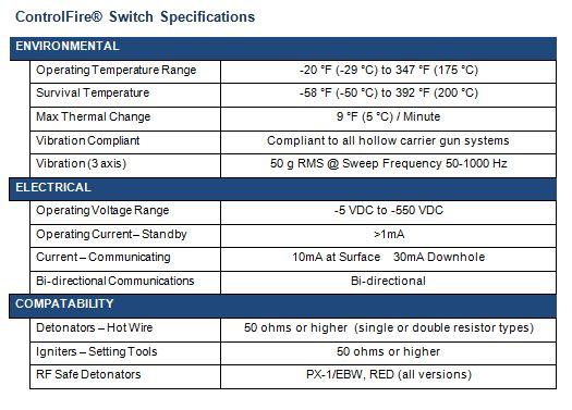
18 ControlFire Specifications
19 ControlFire Part Numbers Titan Part Numbers Description Part Number ControlFire Switch System ControlFire Switch v Command and Control Panel (portable) Command and Control Panel (rack mount) VeriFire Panel Wireline Switch Simulator Panel Panel External Test Block Cable Kit EBFire Feed Thru w/ Ground 9400-EBTW-WG EBFire Feed Thru 9400-EBTW Retainer Nut ¼ ID w/ Ground 9400-EBRN-WG Retainer Nut ¼ ID 9400-EBRN-250 RF-Safe ControlFire System (with Austin Powder detonator selection) RF-Safe Switch with A-85 Detonator DETO-CFA-A85-T RF-Safe Switch with A-96L Detonator DETO-CFA-A96L-T RF-Safe Switch with A-105 Detonator DETO-CFA-A105-T RF-Safe Switch with A Detonator DETO-CFA-A T RF-Safe Switch with A-140 Detonator DETO-CFA-A140-T RF-Safe Switch with A- 140F Detonator DETO-CFA-A140F-T RF-Safe Switch with A- 140S Detonator DETO-CFA-A140S-T Titan Shooting Power Supply ControlFire Shooting Power Supply
20 Contact Website Sales Houston, TX (281) Corporate Office Pampa, TX (806) Technical Support 24/7
ControlFire. June 2013
 ControlFire June 2013 Agenda Selective Switch History ControlFire Advanced Switch System Applications System Overview Safety Benefits and Features Developments Track Record Specifications Part Numbers
DynaSelect System. Plug-n-Perf Optimized
 DynaSelect System Plug-n-Perf Optimized PLUG-N-PERF MADE SAFER, MORE EFFICIENT AND MORE RELIABLE The DynaSelect System sets a new standard in dependable performance safety and operational cost savings
DEEP EXPERIENCE. STRONG REPUTATION.
 DEEP EXPERIENCE. STRONG REPUTATION. We know wireline and what it takes to earn trust in the industry. Our customers have come to count on our experience, technology and reliability. When you want better
REDEFINING PUMP DOWN PERFORATING
 REDEFINING PUMP DOWN PERFORATING 2018-NAPS-37 Authors: Sharif Aboelnaga, Pedro Hernandez, Carlos Eduardo Guedes, Fernando Garcia-Osuna, Schlumberger, Nick Snoke, FHE USA LLC AGENDA REDEFINING PUMP DOWN
output devices. connected to the controller. data communications link. relay systems. user program. MECH1500Quiz1ReviewVersion2 Name: Class: Date:
 Class: Date: MECH1500Quiz1ReviewVersion2 True/False Indicate whether the statement is true or false. 1. The number and type of I/Os cannot be changed in a fixed PLC. 2. In a PLC system, there is a physical
D115 The Fast Optimal Servo Amplifier For Brush, Brushless, Voice Coil Servo Motors
 D115 The Fast Optimal Servo Amplifier For Brush, Brushless, Voice Coil Servo Motors Ron Boe 5/15/2014 This user guide details the servo drives capabilities and physical interfaces. Users will be able to
GUIDE TO ASSEMBLY OF ERICA SYNTHS MIDI-CV MODULE
 GUIDE TO ASSEMBLY OF ERICA SYNTHS MIDI-CV MODULE If you are reading this, most probably, you are about to build Erica Synths DIY MIDI-CV module. This module is mm deep, skiff friendly, has solid mechanical
Adapter Kit - Remote QSI Electronics Installation Instructions
 Adapter Kit Remote QSI Electronics Installation Instructions These installation instructions cover the adapter kit installation of the QSI1, QSI2 and QSI3 versions of communications electronics. The instructions
S Contents. Figure 1. Kyle Form 4C Analog Current Metering Accessory KME
 Reclosers Form 4C Microprocessor-Based Recloser Control Analog Current Metering Accessory KME4-82-1, KME4-82-2 Installation and Operation Instructions Service Information S280-77-8 Figure 1. Kyle Form
P9 ASD Simple Start Guide
 P9 ASD Simple Start Guide Document Number: 64056-002 Date: June, 2011 P9 ASD Simple Start Guide P9 Programming Using the EOI The operating parameters displayed on the LCD screen may be selected, viewed,
Intelligent Solar Charge Controller User s Manual. Please read this manual carefully before you use this product
 Intelligent Solar Charge Controller User s Manual Please read this manual carefully before you use this product Contents 1. Product Introduction... 1 2. Installation... 2 3. Operation... 3 4. Common Fault
The Programmable 4-Way Relay Card is an optional peripheral unit that provides four individually programmable relay output circuits.
 Peripheral Relay The Programmable 4-Way Relay Card is an optional peripheral unit that provides four individually programmable relay output circuits. Up to 16 Cards can be connected to a multi-loop panel
Long Gun Deployment Systems. Jim Gilliat BakerHughes Houston Texas Presentation Number: SLAP 06
 Long Gun Deployment Systems Jim Gilliat BakerHughes Houston Texas Presentation Number: SLAP 06 Wireline Deployment Risk Management Reduce Risk Pre-job planning highlights operational risk Risk mitigation
I-Wheel Conveyance Technology Ultra-Flexible, Ultra-Reliable
 See how we can help you Please contact us to discuss your specific requirements: Technical Centers Fort Worth Technical Center, TX, USA 1132 Everman Parkway, #100 Forth Worth, TX 76140 T +1 817 568 8528
MAXIMA + Series ROTARY LEVEL CONTROL
 Price $5.00 MAXIMA + Series ROTARY LEVEL CONTROL OPERATING INSTRUCTIONS PLEASE READ CAREFULLY Division of Garner Industries 7201 North 98th Street Lincoln, NE 68507-9741 (402) 434-9102 925-0268 TABLE OF
R147 WIRELESS ANTI-TWO-BLOCK INDICATOR
 55M0147GSE00 Rev. E R147 WIRELESS ANTI-TWO-BLOCK INDICATOR Installation and Operation Manual Ref: VH sept 2012 Copyright 2012 RaycoWylie Systems All Rights Reserved. The purpose of this manual is to
ICSI Addressable Disconnect Tool (ADT) Overview
 Overview") ICSI Addressable Disconnect Tool (ADT) Overview Types of Disconnect Tools Offered From left to right: The first tool is the ADT Mod. CF. It is to be utilized when your gun system is comprised of Control
ICSI Addressable Disconnect Tool (ADT) Overview Types of Disconnect Tools Offered From left to right: The first tool is the ADT Mod. CF. It is to be utilized when your gun system is comprised of Control
MC 11 EB-2 Power supply cabinet with external bus, AC version
 MC 11 EB-2 Power supply cabinet with external bus, AC version USER/MAINTENANCE MANUAL 1 SLOT 0 SLOT 1 SLOT 2 SLOT 3 SLOT 4 SLOT 5 SLOT 6 SLOT 7 SLOT 8 SLOT 9 SLOT 10 SLOT 11 EB-2 (a) MC11 (b) (c) Figures
SPECIAL INSTRUCTIONS FOR CAPACITORS COMPACT GENERATORS
 SPECIAL INSTRUCTIONS FOR CAPACITORS COMPACT GENERATORS (WITH CAPACITOR CHARGER BOARD A3517-02) The process depends on Generator and System configuration. This document applies to installation of Capacitors
BA505C 2-wire 4/20mA manual setpoint station Issue 6
 BA505C 2-wire 4/20mA manual setpoint station Issue 6 Issue: 6 3 rd December 2010 2 CONTENTS 1. Description 2. Operation 3. Electrical Systems Design 3.1 4/20mA loop 3.2 Optional Backlights 3.2.1 Separately
EA500. Installation Instructions Transponder
 EA500 EN Installation Instructions Transponder EA500 Installation Instructions 1.0 Overview EN 2 1.0 Overview The EA500 Transponder is the Security Escort module that provides communications between the
INSTALLATION GUIDE NP800R
 INSTALLATION GUIDE ICE - 11, rue Marcel Sembat - 94146 ALFORTVILLE CEDEX - France TEL. : (33) 01 41 79 76 00 - FAX : (33) 01 41 79 76 01 E-MAIL : contact@icelec.com SITE WEB : www.groupeice.com File: A662A
ADA User manual ADA RS-485 / RS-422 to RS-232 Converter. 1 io_ada-4010_v3.22_en. Copyright CEL-MAR sp.j.
 User manual ADA-4010 RS-485 / RS-422 to RS-232 Converter Copyright 2001-2017 CEL-MAR spj 1 io_ada-4010_v322_en Contents 1 GENERAL INFORMATION 3 11 WARRANTED INFORMATION 3 12 GENERAL CONDITIONS FOR SAFE
XDBKITS5 Bus / DB Terminal Kit (Size 5) Installation Manual DPD00116
 Installation Manual DPD00116") XDBKITS5 Bus / DB Terminal Kit (Size 5) Installation Manual DPD00116 XDBKITS5 Option Kit Installation Manual vacon 3 Installing the Bus / DB Terminal Option Kit Introduction The XDBKITS5 option kit is
XDBKITS5 Bus / DB Terminal Kit (Size 5) Installation Manual DPD00116 XDBKITS5 Option Kit Installation Manual vacon 3 Installing the Bus / DB Terminal Option Kit Introduction The XDBKITS5 option kit is
QUINT-BUFFER/24DC/24DC/40
 Buffer module Data sheet 105496_en_01 PHOENIX CONTACT 2013-11-01 1 Description The QUINT BUFFER buffer module combines the electronic switchover unit and power storage in the same housing. The buffer module
4100/ VDC Converter Installation Instructions
 4100/4120-0156 8 VDC Converter Installation Instructions Introduction This publication describes the installation procedure for the 8 VDC Converter. Related Documentation Field Wiring Diagram for 4100
Fiber optic converter audio and CAN TA OPERATION MANUAL
 Fiber optic converter audio and CAN TA-110.1 IOA110-1 March 2009 LANEX S.A., Technical support: tel. ul.ceramiczna 8, 20-150 Lublin tel. +48 81 443 96 36 Contents 1. General Characteristics.... 5 1.1.
* * Agilent Power Distribution Unit (PDU) Installation Guide
 Installation Guide") Agilent Power Distribution Unit (PDU) Installation Guide For use with Agilent PDU kits and PDU installation kits for Agilent instrument racks June 2008 Edition 7 E0608 *5000-0039* 5000-0039 Notice The
Agilent Power Distribution Unit (PDU) Installation Guide For use with Agilent PDU kits and PDU installation kits for Agilent instrument racks June 2008 Edition 7 E0608 *5000-0039* 5000-0039 Notice The
INSTALLATION INSTRUCTIONS
 TT-40 9/0 INSTALLATION INSTRUCTIONS Original Issue Date: 9/0 Model: Automatic Transfer Switches Equipped with the Programmable Controller Market: ATS Subject: External Battery Supply Module Kit GM69-KP
MAXIMA+ Series Rotary Level Indicator
 MAXIMA+ Series Rotary Level Indicator BinMaster: Division of Garner Industries 7201 N. 98th St., Lincoln, NE 68507 402-434-9102 email: info@binmaster.com www.binmaster.com OPERATING INSTRUCTIONS PLEASE
4 Channel 4~20mA/0~10VDC Analog Data Fiber Link System
 USER GUIDE RLH Industries, Inc. The leader in rugged fiber optic technology. U-022 2017A-0330 4 Channel 4~20mA/0~10VDC Analog Data Fiber Link System SYSTEM INSTALLATION INFORMATION Description The 4 Channel
DET-TRONICS. INSTRUCTIONS Eagle Quantum Heart Beat Monitor EQ2400HBM Eagle 2000 Heart Beat Monitor EA2400HBM /99
 INSTRUCTIONS Eagle Quantum Heart Beat Monitor EQ2400HBM Eagle 2000 Heart Beat Monitor EA2400HBM INSTRUCTIONS Heart Beat Monitor EQ2400HBM & EA2400HBM Section I General Information The EA2400HBM and EQ2400HBM
Controllers for compressor racks with advanced energy saving. PN08 September 2016
 page 1 / 16 XC400/600 for small/medium compressor rack management Dixell introduces the new compact parametric controllers for compressor rack with. Dixell presents the XC400/600 series, dedicated to the
Nevco Message Center Installation Manual Retain this manual in your permanent file. 08/27/ Rev. C
 Nevco Message Center Installation Manual Retain this manual in your permanent file. 08/27/2014 135-0144 Rev. C Table of Contents INSTALLATION INSTRUCTIONS... 1 UNPACKING THE EQUIPMENT... 1 MESSAGE CENTER
Product Data Sheet. BMS/Graphics Interface. Features
 BMS/Graphics Interface Product Data Sheet Features The Mxp-010 interface allows BMS systems and graphics PCs to be integrated with the Mx- 4000 series of Fire Control Panels and Remote Terminals. The interface
INSTALLATION MANUAL SLI 50 INVERTER
 INSTALLATION MANUAL SLI 50 INVERTER www.unipowerco.com Manual No. SLI-50-48-3 2016 UNIPOWER LLC All Rights Reserved UNIPOWER LLC 3900 Coral Ridge Drive, Coral Springs, Florida 33065, USA sales@unipowerco.com
Installation manual CF8-W-Disp-AL
 Installation manual CF8-W-Disp-AL CO 2 transmitter with two relays mounted in industrial housing prepared for Modbus communication protocol 4 7 8 8 6 3 2 5 Wall plate 5 Snap-in lid 2 PCB (Factory supplied
MAXIMA + Series ROTARY LEVEL CONTROL
 Price $5.00 MAXIMA + Series ROTARY LEVEL CONTROL OPERATING INSTRUCTIONS PLEASE READ CAREFULLY Division of Garner Industries 7201 North 98th Street Lincoln, NE 68507-9741 (402) 434-9102 925-0268 Rev. A
GT- IRDM-9603 Product description Rev. 2 17/06/2014
 GT- IRDM-9603 Product description Rev. 2 17/06/2014 1 1. Overview The GT- IRDM- 9603 is a complete Satellite Terminal solution for Satellite applications. Based on IRIDIUM 9603 module. 2. Hardware Interface
Basketball Shot Clock Set LX2180 Manual
 Basketball Shot Clock Set LX2180 Manual 72 Industrial Boulevard Wrightsville, GA 31096 Phone: (800) 445-7843 Fax: (800) 864-0212 www.electro-mech.com LX2180 Revision 5 February 8, 2013 Table of Contents
DPAK IGBT Motor Drive Reference Design Kit
 Description DPAK IGBT Motor Drive Reference Design Kit The reference design power board is designed to showcase IR DPAK IRGR4610DPBF IGBT in a motor drive application. Product Summary IGBT inverter power
Operating Instructions VEGAMET 381
 Operating Instructions VEGAMET 381 in out Contents Contents 1 About this document... 4 1.1 Function... 4 1.2 Target group... 4 1.3 Symbolism used... 4 2 For your safety... 6 2.1 Authorised personnel...
PS/IO Circuit Board Retrofit
 S&C 6800 Series Automatic Switch Controls PS/IO Circuit Board Retrofit Table of Contents Section Page Introduction Qualified Persons.... 2 Read this Instruction Sheet.... 2 Retain this Instruction Sheet....
Improving Data Quality in Challenging Wells. Logging Services. UltraSlim SM. Solving challenges.
 Improving Data Quality in Challenging Wells UltraSlim SM Logging Services Solving challenges. UltraSlim SM Logging Services High-Quality Logging, Now in a Smaller Package Halliburton s new UltraSlim logging
Sidewinder Pumps Inc. AC C1D2 Timer/Controller
 Sidewinder Pumps Inc. AC C1D2 Timer/Controller Page 1 of 14 Rev 4/26/17 Table of Contents 1. Warnings --------------------------------------------------------------------------------------------------
PowerCore Model TEC-10 Installation Manual
 PowerCore Model TEC-10 Installation Manual Products covered in this document comply with European Council electromagnetic compatibility directive 2014/30/EU and electrical safety directive 2014/35/EU.
Instruction Manual. Electrical Management System (EMS) EMS-HW30C & EMS-HW50C
 EMS-HW30C & EMS-HW50C") Instruction Manual Electrical Management System (EMS) EMS-HW30C & EMS-HW50C EMS-HW50C EMS-HW30C! CAUTION These instructions are intended to provide assistance with the installation of this product, and
Instruction Manual Electrical Management System (EMS) EMS-HW30C & EMS-HW50C EMS-HW50C EMS-HW30C! CAUTION These instructions are intended to provide assistance with the installation of this product, and
Blackout Shutter Kits with Breathable Wall Light Traps
 Blackout Shutter Kits with Breathable Wall Light Traps 2018 Growers Supply All Rights Reserved. Reproduction is prohibited without permission. Maintain controlled airflow without sacrificing blackout environments.
MODEL NC105 DIGITAL CODED SQUELCH ENCODER/DECODER INSTRUCTION MANUAL
 15385 Carrie Drive Grass Valley, CA 95959 Office: (530) 477-8400 Tech. Support: (530) 477-8402 FAX: (530) 477-8403 Sales: (800) 874-8663 Email: tech@norcommcorp.com Web: www.norcommcorp.com MODEL NC105
CHAPTER 3B: ELECTRONIC POWER STEERING
 Electronic Power Steering CHAPTER 3B: ELECTRONIC POWER STEERING NOTE: The basic steering system, such as the tie rod ends, drag links axles, etc., is covered in Chapter 3A: Steering. In 2012, Cub Cadet
Mounting DIGITAL DISPLAY
 Mounting The Class digital display mounts in a. by. cutout. Overall area necessary for installation is. by.. Two 0.0 diameter holes are provided for mounting screws..0".0..0.900 Ø 0.0" () HOLES."." DIGITAL
Aarlogic TER-GX910. Product description. Rev.9 17/03/2013
 Aarlogic TER-GX910 Product description Rev.9 17/03/2013 Contents 1 Overview... 3 2 Hardware Interface Description... 3 2.1 Main features of the TER-GX910... 3 2.2 Hardware block diagram... 4 3 Interface
Table of Contents. General Information. Document Sure-Aire Flow Monitoring System. User and Service Manual WARNING CAUTION
 Document 476092 User and Service Manual Installation, Operation and Maintenance Manual Please read and save these instructions for future reference. Read carefully before attempting to assemble, install,
MODEL NC400 MULTI-FUNCTION TOUCH-TONE DECODER INSTRUCTION MANUAL
 15385 Carrie Drive Grass Valley, CA 95959 Office: (530) 477-8400 Tech. Support: (530) 477-8402 FAX: (530) 477-8403 Sales: (800) 874-8663 Email: tech@ norcommcorp.com Web: www.norcommcorp.com MODEL NC400
MODIFYING THE ACS355 UL TYPE 4X FOR MXXX OPTIONS
 MODIFYING THE ACS355 UL TYPE 4X FOR MXXX OPTIONS Description: The following instructions are designed to provide a step by step procedure; how to modify the ACS355 UL Type 4X drive for Mxxx-01 (MPOW-01,
S Reclosers Kyle Type VXE Electronic Control SCADA Input/Output Board Installation and Operation Instructions
 Reclosers Kyle Type VXE Electronic Control SCADA Input/Output Board Installation and Operation Instructions Cooper Power Systems Service Information S0-6- Applicable to VXE5 reclosers serial number 006
TraceTek Leak Detection Master Module Installation Instructions TOOLS REQUIRED STORAGE
 TTDM-128 TraceTek Leak Detection Master Module Installation Instructions TRACETEK APPROVALS AND CERTIFICATIONS TYPE NM General Signaling Equipment 76LJ GENERAL INFORMATION Please read these instructions
PWRguard PLUS Spring City Drive Waukesha, WI
 PWRguard PLUS www.westmountainradio.com 1020 Spring City Drive Waukesha, WI 53186 262-522-6503 sales@westmountainradio.com 2016, All rights reserved. All trademarks are the property of their respective
Aarlogic TER-GX910. Product description. Rev.9 17/03/2013
 Aarlogic TER-GX910 Product description Rev.9 17/03/2013 Contents 1 Overview... 3 2 Hardware Interface Description... 3 2.1 Main features of the TER-GX910... 3 2.2 Hardware block diagram... 4 3 Interface
Instruction Sheet Board Style Low Water Cutoff
 Instruction Sheet Board Style Low Water Cutoff 102-305 SUPERSEDES: REVISION E DATED December 12, 2007 #5401173-REV F PLANT ID 001-3902 US Patents 6,904,800, 7,243,540, and 7,317,993 Other Patents Pending
EL7060 Series SERVICE MANUAL
 EL7060 Series SERVICE MANUAL 1 TABLE OF CONTENTS 1 General description... 4 1.1 Exploded view... 5 2 ACCESSIBILITY... 5 2.1 Dust Bag Cover.. 7 2.2 Display Cover.8 2.3 PCB Display/Switch..9 2.4 Top Cover..10
RTK3 Logic Controller User Manual Revised
 RTK3 Logic Controller User Manual Revised 6-24-08 1 of 16 svn://software/hardware/rtk3/docs/rtk3_man.doc MRR 6/24/08 9:03 AM Overview The RTK3 is intended to simplify and expedite control wiring. Centroid
Adapter Kit - QSI Electronics to TM Meter Installation Instructions
 Adapter Kit - QSI Electronics to TM Meter Installation Instructions These installation instructions cover the adapter kit installation of the QSI1, QSI2 and QSI3 versions of communications electronics
Product Datasheet. Touch screen Part number OPERATOR INTERFACE
 OPERATOR INTERFACE Application Main operating and indication panel for water based fire suppression systems. Each screen are designed for easy understanding without any nice to have function. The basic
FFI. Advances in Medium and Low Voltage Power Distribution ESS Metron Expo and Technical Seminars. Presented By: Greg Pelster & Robert Schmid
 Advances in Medium and Low Voltage Power Distribution ESS Metron Expo and Technical Seminars Presented By: Greg Pelster & Robert Schmid FFI Ferrie, Franzmann Industries LOW VOLTAGE SWITCHGEAR & LOW VOLTAGE
OMNITERM LPI & LPD Loop Powered Isolators DATASHEET. Model C2063B LPI (single) & C2462A LPD (dual) 4-20mA Loop Powered Isolators.
 & C2462A LPD (dual) 4-20mA Loop Powered Isolators.") Model C0B (single) & CA LPD (dual) 0mA Loop Powered Isolators Features Isolate any instrument current loop to 0ac Powered by the current loop no power supply required Lowest volt drop < Volts at 0 ma (,V
Model C0B (single) & CA LPD (dual) 0mA Loop Powered Isolators Features Isolate any instrument current loop to 0ac Powered by the current loop no power supply required Lowest volt drop < Volts at 0 ma (,V
Compact Keypad. ins /02/2010. Exit button (push to make) 12V DC release current rating must be less than 1A.
 12V DC release current rating must be less than 1A.") Compact Keypad Grey Exit button (push to make) 1V DC White Black 115V DC (fuse rating 1A) 1V DC release current rating must be less than 1A. The diode current rating must be equal to or greater than the
Compact Keypad Grey Exit button (push to make) 1V DC White Black 115V DC (fuse rating 1A) 1V DC release current rating must be less than 1A. The diode current rating must be equal to or greater than the
CAN bus switch panels mounted either on the dash or the steering wheel allow for vastly simplified wiring and reduced weight.
 POWER MANAGEMENT UNIT PMU-16 PMU-16 Decades ago, the critical electronic components in a race car were the ignition coil and points. Race cars are now sophisticated machines equipped with advanced engine
Blackout Shutter Kits with Breathable Wall Light Traps
 Blackout Shutter Kits with Breathable Wall Light Traps 2018 Growers Supply All Rights Reserved. Reproduction is prohibited without permission. Revision date: 05.10.18 Maintain controlled airflow without
Connecting a Cisco Input Module
 CHAPTER 4 Overview The optional Cisco Input Module (Figure 4-1) is attached to a Cisco Physical Access Gateway or Cisco Reader Module to provide additional connections for up to ten input devices. Each
RSTI-EP Slice I/O. PROFINET Scanner EPXPNS001. GFK-2965C November 2017
 November 2017 Ethernet Ports PWR, SF, BF, MT, LINK 1, ACT 1, LINK 2, and ACT 2 LEDs Door for Micro USB Port PROFINET Scanner Power Supply LED RSTI-EP Slice I/O PROFINET Scanner The PROFINET Scanner is
Operation Manual Profibus DP -Display HE 5120 P with digital I/O's
 Operation Manual Profibus DP -Display HE 510 P with digital I/O's "HESCH" Schröder GmbH Boschstraße 8 31535 Neustadt Telefon +49 (0) 503 / 9535-0 Telefax +49 (0) 503 / 9535-99 e-mail: info@hesch.de http://www.hesch.de
32-Channel Analogue Input Module Differential Input
 MAI32*AD 32-Channel Analogue Input Module Differential Input (MAI32*AD) Issue 4 October 2005 INTRODUCTION PURPOSE The Analogue Input Module provides up to 32, low voltage or current analogue input signals.
SECTION N -- ELECTROSTATIC DISCHARGE (ESD)
") INSTALLATION REQUIREMENTS AT&T January, 2012 Section N, ATT-TP-76300 Revised NA SECTION N -- ELECTROSTATIC DISCHARGE (ESD) CONTENTS PAGE 1. GENERAL... N-1 1.1. Introduction... N-1 1.2. General Requirements...
INSTALLATION REQUIREMENTS AT&T January, 2012 Section N, ATT-TP-76300 Revised NA SECTION N -- ELECTROSTATIC DISCHARGE (ESD) CONTENTS PAGE 1. GENERAL... N-1 1.1. Introduction... N-1 1.2. General Requirements...
ELECTROM INSTRUMENTS
 ELECTROM INSTRUMENTS LEADING THE INDUSTRY FOR OVER TWENTY YEARS INTRODUCING THE NEW itig Winding Analyzer Designed and built with reliable digital components. Rugged and dependable. For the electric motor
Propeller Project Board USB (#32810)
") Web Site: www.parallax.com Forums: forums.parallax.com Sales: sales@parallax.com Technical: support@parallax.com Office: (916) 624-8333 Fax: (916) 624-8003 Sales: (888) 512-1024 Tech Support: (888) 997-8267
Web Site: www.parallax.com Forums: forums.parallax.com Sales: sales@parallax.com Technical: support@parallax.com Office: (916) 624-8333 Fax: (916) 624-8003 Sales: (888) 512-1024 Tech Support: (888) 997-8267
Product Data Sheet. Hochiki 8 Way I/O Card. Features
 Hochiki 8 Way I/O Card Product Data Sheet Features The Mxp-019 is a stand-alone fire system peripheral based on the Hochiki ESP protocol for use with the Mx-4000 range of panels. The unit connects to the
Magnum Club Smoke System
 AND INSTALLATION VERSION.0 Martin Professional A/S,Olof Palmes Allé 8, DK-800,Aarhus N Phone: +45 87 40 00 00 Internet: www.martin.dk Magnum Club Smoke System Fluids Suitable for this system: CONNECTIONS
Physical description of the safety modules
 Implementing safety modules Physical description of the safety modules Introduction The TSX PAY 262 modules are in standard Premium PLC interface format. They occupy a single slot. Illustration The following
Instruction book IQAN-LST. Publ no HY /UK Edition 0301
 Instruction book IQAN-LST Publ no HY17-8364/UK Edition 0301 Contents 1 Introduction......................................................2 2 Precautions.......................................................3
RMB Peripheral Units Installation Guide
 RMB Peripheral Units Installation Guide Part Number 65-000101 2011 by Kentrox, Inc. All rights reserved. Copyright 2011 by Kentrox, Inc. All Rights Reserved. The material discussed in this publication
Assembly Instructions CT-E Screen Read Board
 Assembly Instructions CT-E Screen Read Board If you ever need to use your CT-1024 terminal system in a situation where you need to get edited information that has been typed onto the screen, transmitted
Overview of the Cisco Wireless Gateway for LoRaWAN
 Overview of the Cisco Wireless Gateway for LoRaWAN This chapter provides an overview of the Cisco Wireless Gateway for LoRaWAN and contains the following sections: About Cisco Wireless Gateway for LoRaWANs,
CDD Carbon Dioxide Transmitter
 Introduction The OSA CO2 transmitter uses Infrared Technology to monitor CO2 levels within a range of 0 2000 ppm and outputs a linear 4-20 ma or 0-5/0-10 Vdc signal. The enclosure is designed to operate
Installation Instructions
 Installation Instructions Cat. No. 1771-OND Series B This document provides information on: important pre-installation considerations power supply requirements installing the module setting the fault mode
Installation Guide. Retrofit Kit for USB Ready Intraoral Systems
 Installation Guide Retrofit Kit for USB Ready Intraoral Systems Table of Contents Wall-Mount Retrofit Kit... 2 Introduction... 2 Connecting the Articulating and Horizontal Arm Cables... 2 Installing the
PT230 PONTOON THRUSTER INSTALLATION MANUAL (PATENT PENDING) VOLUME 1.2, JUNE 2015
 VOLUME 1.2, JUNE 2015") PT230 PONTOON THRUSTER (PATENT PENDING) INSTALLATION MANUAL VOLUME 1.2, JUNE 2015 Sideshift Inc. 130 Industrial Ave, Unit 303, Carleton Place, ON, Canada K7C 3T2 1.877.325.4787 +613.686.6011 INFO@SIDESHIFT.COM
PT230 PONTOON THRUSTER (PATENT PENDING) INSTALLATION MANUAL VOLUME 1.2, JUNE 2015 Sideshift Inc. 130 Industrial Ave, Unit 303, Carleton Place, ON, Canada K7C 3T2 1.877.325.4787 +613.686.6011 INFO@SIDESHIFT.COM
Butterfly Laser Diode Mount
 LM14S2 Butterfly Laser Diode Mount Operating Manual LM14S2 Laser On TEC Driver LD Driver THORLABS, Inc. Ph: (973) 579-7227 435 Route 206N Fax: (973) 383-8406 Newton, NJ 07860 USA www.thorlabs.com 10614-D02
AG300 Family CTL01-3A-03, AMP01-2A-02
 AG300 Family CTL01-3A-03, AMP01-2A-02 Hardware User's Manual Page 1 Revision control table Version Description Date 1.0 Initial (based on Hardware Manual of previous hardware versions) April 27, 2016 1.1
SQ405 Controller CAUTION. The caution messages are displayed before procedures which, if not followed, could cause damage to the equipment.
 87-900-112-01 (A) April 18th, 2011 INSTRUCTIONS SQ405 Controller GENERAL INFORMATION This equipment is destined for use by professionals. The user should read this instruction manual and any other additional
4-20mA SERIES Single or Dual Axis MEMS Inclinometer
 4-20mA SERIES Single or Dual Axis MEMS Inclinometer The 2GIG 4-20mA Inclinometer is engineered to work for all applications. The internal software provides unlimited programming capabilities. It offers
TT /12b INSTALLATION INSTRUCTIONS. Introduction
 TT-1545 11/12b INSTALLATION INSTRUCTIONS Original Issue Date: 6/10 Model: 20-300 kw Generator Sets Market: Industrial Subject: Decision-Maker 3000 Controller Service Replacement Kit GM75376 Introduction
MSR 2400R. Rugged Power System for Military and Heavy Duty Applications
 MSR 2400R Rugged Power System for Military and Heavy Duty Applications 2400 W modular power system Power supply or battery charging systems Parallel n+1 connection, up to 90A Series connection, up to 360VDC
D Issue D Original. Instruction Manual. Micro Tool Interface
 Instruction Manual D373-60-880 Issue D Original Micro Tool Interface Description SPI Micro-TIM MCM Micro-TIM TEL Micro-TIM SEMI E73 Micro-TIM LAM Alliance Micro-TIM Novellus C3 Micro-TIM Hitachi Micro-TIM
Circuit Breaker Sentinel (CBS) for SF 6. power circuit breakers
 for SF 6. power circuit breakers") Circuit Breaker Sentinel (CBS) for SF 6 power circuit breakers Circuit Breaker Sentinel (CBS) for SF 6 power circuit breakers It is widely recognized that the concept of periodic equipment maintenance
Circuit Breaker Sentinel (CBS) for SF 6 power circuit breakers Circuit Breaker Sentinel (CBS) for SF 6 power circuit breakers It is widely recognized that the concept of periodic equipment maintenance
CA-A480-A Elevator Controller. Reference & Installation Manual
 CA-A480-A Elevator Controller Reference & Installation Manual TABLE OF CONTENTS INTRODUCTION.................................................................. 4 Introduction.............................................................................................
Adapter Kit - QSI Electronics to G2 Meter Installation Instructions
 Adapter Kit - QSI Electronics to G2 Meter Installation Instructions These installation instructions cover the adapter kit installation of the QSI1, QSI2 and QSI3 versions of communications electronics
USER S MANUAL VER.1. C10D- PARALLEL PORT INTERFACE CARD BOARD Rev. 1
 USER S MANUAL VER.1 C10D- PARALLEL PORT INTERFACE CARD BOARD Rev. 1 MARCH 2018 User s Manual Page i USER'S MANUAL TABLE OF CONTENTS Contents Page # 1.0 OVERVIEW... iii 2.0 FEATURES... iii 3.0 SPECIFICATIONS...
JUMO PINOS L01. Calorimetric flow sensor. Brief description. Special features. Customer benefits. Data Sheet
 sales@jumo.co.uk info.us@jumo.net Page 1/9 JUMO PINOS L01 Calorimetric flow sensor Brief description The JUMO PINOS L01 flow sensor serves the measuring and monitoring of flow velocities of water and aqueous
Microlok Data Design Records (Addressing, File Control, Checking, and FAT Testing)
") Discipline: Engineering (Signalling) Category: Procedure Microlok Data Design Records (Addressing, File Control, Checking, and FAT Testing) ESD-05-11 Applicability ARTC Network Wide Primary Source Signal
Discipline: Engineering (Signalling) Category: Procedure Microlok Data Design Records (Addressing, File Control, Checking, and FAT Testing) ESD-05-11 Applicability ARTC Network Wide Primary Source Signal