The accessories described in this manual are of the highest quality, carefully designed and built in order to ensure excellent performance.
|
|
|
- Alexandra Bryan
- 5 years ago
- Views:
Transcription
1
2
3 INTRODUCTION Thank you for choosing our product. The accessories described in this manual are of the highest quality, carefully designed and built in order to ensure excellent performance. This manual contains detailed instructions on how to install and use the product. This manual must be stored in a safe place and CONSULTED BEFORE USING THE DEVICE for proper usage instructions as well as maximum performance from the device itself. NOTE: Some images contained in this document are for informational purposes only and may not faithfully demonstrate the parts of the product they represent. SAFETY This part of the manual contains SAFETY precautions that must be followed scrupulously. Ensure that the connectors subjected to high voltages are correctly isolated. The device has been designed for professional use and is therefore not suitable for use in the home. The device has been designed to operate only in closed environments. It should be installed in rooms where there are no inflammable liquids, gas or other harmful substances. Take care that no water or liquids and/or foreign bodies fall into the device. In the event of a fault and/or impaired operation of the device, do not attempt to repair it but contact the authorized service centre. The device must be used exclusively for the purpose for which it was designed. Any other use is to be considered improper and as such dangerous. The manufacturer declines all responsibility for damage caused by improper, wrong and unreasonable use. ENVIRONMENTAL PROTECTION Our company devotes abundant resources to analysing environmental aspects in the development of its products. All our products pursue the objectives defined in the environmental management system developed by the company in compliance with applicable standards. Hazardous materials such as CFCs, HCFCs or asbestos have not been used in this product. When evaluating packaging, the choice of material has been made favouring recyclable materials. Please separate the different material of which the packaging is made and dispose of all material in compliance with applicable standards in the country in which the product is used. DISPOSING OF THE PRODUCT The device contains internal material which (in case of dismantling/disposal) are considered TOXIC, such as electronic circuit boards. Treat these materials according to the laws in force, contacting qualified centres. Proper disposal contributes to respect for the environment and human health. The reproduction of any part of this manual, even in part, is prohibited unless authorised by the manufacturer. The manufacturer reserves the right to change the product described at any time without prior notice for improvement purposes
4 INDEX PRESENTATION 5 IN THE BOX 5 EXTERNAL VIEW 5 PROFIBUS DP GATEWAY CONNECTORS AND LEDS 6 PROFIBUS CONNECTOR 6 POWER CONNECTOR 6 MULTICOM 302 CONNECTOR 6 STATUS LEDS 6 MULTICOM 302 JUMPER AND DIP SWITCHES SETTINGS 7 INSTALLATION 7 PROFIBUS CONFIGURATION SWITCHES 8 CONNECTION CABLE MULTICOM 302 PROFIBUS DP GATEWAY 8 DIN RAIL MOUNTING 8 PROFIBUS I/O DATA 9-4 -
5 PRESENTATION MultiCOM 411 is a complete PROFIBUS-DP slave according to IEC It allows to integrate the management and monitoring of the UPS into a PROFIBUS network. Baud rates from 9.6 kbit/s up to 12 Mbit/s are supported and automatically detected. IN THE BOX MultiCOM 302 board PROFIBUS DP Gateway Connection cable between MultiCOM 302 and PROFIBUS DP Gateway EXTERNAL VIEW PROFIBUS Connector Configuration Switches Status LEDs Reserved MultiCOM 302 Connector Power Connector DIN-rail Connector - 5 -
 8 A-Line Negative RxD/TxD (RS485) 1 May be used by some devices to determine the direction")

6 PROFIBUS DP GATEWAY CONNECTORS AND LEDS PROFIBUS CONNECTOR PIN Signal Description Housing Shield Bus cable shield, connected to PE 1, 2, 7, B-Line Positive RxD/TxD (RS485) 4 RTS 1 Request To Send 5 GNDBUS 2 Isolated GND from RS-485 side 6 +5V BUS 2 Isolated +5 V output from RS-485 side (80 ma max) 8 A-Line Negative RxD/TxD (RS485) 1 May be used by some devices to determine the direction of transmission 2 Used for bus termination; may also be used to power optical transceivers (RS485 to fibre optics) (female) POWER CONNECTOR PIN Description VDC (300 ma required) 2 GND Note: no power supply is provided with the device. MULTICOM 302 CONNECTOR PIN Description 5 1 1, 2, 3, 4, 6, 7-5 Signal Ground 8 RS RS (female) STATUS LEDS # State Status 1 - PROFIBUS Online Off Not online Green Online 2 - PROFIBUS Offline Off Not offline Red Offline 3 - (Not used) PROFIBUS Diagnostic 5 - Subnet Status 6 - Device Status Off Red, flashing 1Hz Red, flashing 2Hz Red, flashing 4Hz Off Green, flashing Green Red Off Alternating Red/Green Green Green, flashing Red Red, flashing No diagnostics present Error in configuration Error in user parameter data Error in initialization Power off Running correctly, but errors occurred Running Subnet error Power off Invalid or missing configuration Initializing Running Bootloader mode Contact support department - 6 -
7 MULTICOM 302 JUMPER AND DIP SWITCHES SETTINGS INSTALLATION 1. Remove the cover of the UPS expansion slot by removing the two retaining screws. 2. Insert MultiCOM 302 in the slot. 3. Fix the cover provided using the screws previously removed. 4. Connect the PROFIBUS DP Gateway to the MultiCOM 302 using the cable provided with the device. NOTE: if necessary, you can also use another cable realized in accordance with the specifications (see Connection cable MultiCOM 302 PROFIBUS DP Gateway). 5. Set the PROFIBUS node ID (see Configuration Switches). 6. Connect the PROFIBUS DP Gateway to the PROFIBUS DP Network. 7. Connect the power cable and apply power
8 PROFIBUS CONFIGURATION SWITCHES The configuration switches are used to set the PROFIBUS node address. Remove the plastic hatch to configure the switches (see image below). Note that the node address cannot be changed during runtime, i.e. the gateway requires a reset for changes to have effect. The configuration is done using two rotary switches as follows: Node Address = (Switch B x 10) + (Switch A x 1) Note: When removing the hatch and configuring the switches, avoid touching the circuit boards and components. Example: If the node address should be 42: set switch A to 2 and switch B to 4. CONNECTION CABLE MULTICOM 302 PROFIBUS DP GATEWAY DB9 male PIN connect to RJ-45 PIN NOTE: Use a twisted pair to connect PIN #9 and #8 of DB9 to PIN #3 and #4 of RJ-45 DIN RAIL MOUNTING To snap the gateway on, first press it downwards (1) to compress the spring in the DIN-rail mechanism, then push it against the DIN-rail as to make it snap on (2). To snap the gateway off, push it downwards (1) and pull it out from the DIN-rail (2), as to make it snap off from the DIN-rail
9 PROFIBUS I/O DATA The UPS s values are presented to the Master PLC/Controller as easily processed I/O data. INPUT DATA REGISTER # BYTE # High Low DESCRIPTION UNIT States / alarms States / alarms Charge% % Autonomy Minutes RESERVED Load phase L1 % Load phase L2 % Load phase L3 % Input voltage (Ph-N) V1 V Input voltage (Ph-N) V2 V Input voltage (Ph-N) V3 V Input frequency Hz/ Output voltage (Ph-N) V1 V Output voltage (Ph-N) V2 V Output voltage (Ph-N) V3 V Output frequency Hz/ Output current phase L1 A/ Output current phase L2 A/ Output current phase L3 A/ Output peak current phase L1 A/ Output peak current phase L1 A/ Output peak current phase L1 A/ Battery current of positive bench A/ Battery current of negative bench A/ Battery voltage of positive bench V/ Battery voltage of negative bench V/ Output active power phase L1 kw/ Output active power phase L2 kw/ Output active power phase L3 kw/ Output apparent power phase L1 kva/ Output apparent power phase L2 kva/ Output apparent power phase L3 kva/ Bypass voltage (Ph-N) V1 V Bypass voltage (Ph-N) V2 V Bypass voltage (Ph-N) V3 V Bypass frequency Hz/ System temperature C - 9 -
10 INPUT DATA REGISTER # BYTE # High Low DESCRIPTION UNIT RESERVED Battery temperature C Power 1 temperature C Power 2 temperature C Power 3 temperature C Input current phase L1 A/ Input current phase L2 A/ Input current phase L3 A/ RESERVED RESERVED RESERVED Output nominal voltage V Output nominal frequency Hz/ Output nominal power kw/ Output nominal power kva/ Battery nominal voltage V Battery nominal capacity Ah RESERVED Time from last valid UPS data processed Seconds Echo of command code Integer Echo of shutdown delay time Seconds Echo of restore delay time Minutes Command result: 0x0F00 Ready to receive command x0100+Command Code Command code is wrong 0x0200+Command Code Command is not handled 0x0300+Command Code Parameter out of range (Reg. 116) 0x0E00+Command Code Command sent to the UPS RESERVED RESERVED RESERVED RESERVED RESERVED Integer Some measures may not be available for all the UPS. In this case, the relative register remains at 0xFFFF value. STATES / ALARMS 1 BIT # DESCRIPTION 15 (MSB) Output powered [0=NO / 1=YES] 14 UPS locked [0=NO / 1=YES] 13 Battery working [0=NO / 1=YES] 12 Battery low [0=NO / 1=YES] 11 On bypass [0=NO / 1=YES] 10 9 Normal operation [0=NO / 1=YES] 8 7 Bypass bad [0=NO / 1=YES] 6 Battery charging [0=NO / 1=YES] 5 Battery charged [0=NO / 1=YES] 4 3 Shutdown active [0=NO / 1=YES] 2 1 Test in progress [0=NO / 1=YES] 0 (LSB)
11 STATES / ALARMS 2 BIT # DESCRIPTION 15 (MSB) UPS failure [0=NO / 1=YES] 14 Alarm overload [0=NO / 1=YES] 13 Alarm temperature [0=NO / 1=YES] 12 Input mains present [0=NO / 1=YES] (LSB) REGISTER # BYTE # High Low OUTPUT DATA DESCRIPTION Command Code: 0 (0x0000) Get ready to receive a new command 1 (0x0001) System Shutdown (see also register 2) 2 (0x0002) System Shutdown & Restore (see also register 2-3) 3 (0x0003) Delete Commands 1 & 2 12 (0x000C) UPS on Bypass 20 (0x0014) Test Battery UNIT Integer Shutdown delay time Seconds Restore delay time Minutes NOTE 1: write always 0x0000 in Command Code after executing a command in order to get ready the device to accept the next command. NOTE 2: before executing a new command, you can check if the device is ready to accept it by verifying that Command Result = 0x0F00 (INPUT DATA register 60) NOTE 3: write in register 2 and 3 ( Shutdown delay time and Restore delay time ) before writing in register 1 for executing a system shutdown or a system shutdown & restore otherwise, writing in register 2 and 3 will have no effect. Example of Power OFF the UPS in 3 minutes and Power ON after 8 hours (System Shutdown & Restore): Check that "Command Result" (INPUT DATA register 60) is equal to 0x0F00. Write 0x00B4 in Shutdown delay time (output data / register 2) Verify that "Echo of shutdown delay time" (INPUT DATA register 58) is equal to the value sent. Write 0x01E0 in Restore delay time (output data / register 3) Verify that "Echo of restore delay time" (INPUT DATA register 59) is equal to the value sent. Write 0x0002 in Command Code (output data / register 1) Verify that command result is 0x0E02 (input data / register 60) Write 0x0000 in Command Code (output data / register 1)


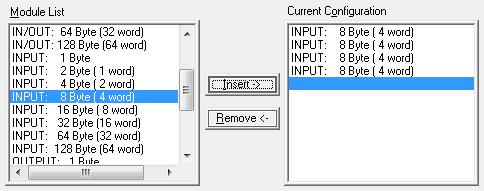
12 Example of master configuration to have accesso to UPS state and commands Example of master configuration to have accesso to all UPS measurements and commands Example of master configuration to have access to the UPS input data register from n 1 to n
13
14 0MNACCMC8ENUB
The accessories described in this manual are of the highest quality, carefully designed and built in order to ensure excellent performance.
 INTRODUCTION Thank you for choosing our product. The accessories described in this manual are of the highest quality, carefully designed and built in order to ensure excellent performance. This manual
The accessories described in this manual are of the highest quality, carefully designed and built in order to ensure excellent performance.
 User Manual INTRODUCTION Thank you for choosing our product. The accessories described in this manual are of the highest quality, carefully designed and built in order to ensure excellent performance.
The accessory described in this manual is a high quality product that has been carefully designed and manufactured to guarantee optimal performance.
 INTRODUCTION Thank you for choosing our product. The accessory described in this manual is a high quality product that has been carefully designed and manufactured to guarantee optimal performance. This
MCD 200 MCD 500. Remove the Profibus Module using the following procedure: 1. Remove power from the module.
 Installation INSTALLATION INSTRUCTIONS: MCD PROFIBUS MODULE Order Code: 175G9001 1. Installation 1. Remove control power and mains supply from the soft starter. 2. Attach the module to the soft starter
- 15G0078B110 - PROFIBUS MODULE INSTRUCTIONS FOR ASAC-0/ASAC-1/ASAB
 - 5G0078B0 - PROFIBUS MODULE INSTRUCTIONS FOR ASAC-0/ASAC-/ASAB Issued on 5/06/2 R. 0 This manual is integrant and essential to the product. Carefully read the instructions contained herein as they provide
It is the installer's responsibility to follow all instructions in this manual and to follow correct electrical practice.
 Important User Information User Manual: MCD Profibus Module Order Code: 175G9001 1. Important User Information Observe all necessary safety precautions when controlling the soft starter remotely. Alert
Observe all necessary safety precautions when controlling the soft starter remotely. Alert personnel that machinery may start without warning.
 MCD Profibus Module Instructions Important User Information Installation Instruction: MCD Profibus Module Order Code: 175G9001 1. Important User Information Observe all necessary safety precautions when
Copyright: December 2017 Nidec Issue: E
 General Information The manufacturer accepts no liability for any consequences resulting from inappropriate, negligent or incorrect installation or adjustment of the optional parameters of the equipment
VersaMax IP Input Module
 Module is used to accept digital input signals. Module Specifications Housing dimensions (width x height x depth) Connection style Operating temperature Storage temperature Operating/storage humidity 60mm
EL731 PROFIBUS INTERFACE
 Tel: +1-800-832-3873 E-mail: techline@littelfuse.com www.littelfuse.com/el731 EL731 PROFIBUS INTERFACE Revision 0-A-032816 Copyright 2016 Littelfuse Startco All rights reserved. Document Number: PM-1011-EN
DF PROFI II PCIe. Installation Instructions V Project No.: 5302 Doc-ID.: DF PROFI II PCIe KUNBUS
 DF PROFI II PCIe Installation Instructions V1.6 27.02.2017 Project No.: 5302 Doc-ID.: DF PROFI II PCIe KUNBUS h:\dokumente\project\5302_df_profi_ii\anwenderdoku\installation\pcie\kunbus\version_1.5\df
DF PROFI II CPCI. Installation Instructions V Project No.: 5302 Doc-ID.: DF PROFI II CPCI KUNBUS
 DF PROFI II CPCI Installation Instructions V1.7 27.02.2017 Project No.: 5302 Doc-ID.: DF PROFI II CPCI KUNBUS h:\dokumente\project\5302_df_profi_ii\anwenderdoku\installation\cpci\kunbus\version_1.6\df
When any of the following symbols appear, read the associated information carefully. Symbol Meaning Description
 Vision OPLC V130 COM Modules: V100-17-CAN, V100-17-RS4/X, V100-17-ET2 This guide shows you how to install an additional communication module in a V130 controller. Instructions and technical specifications
SBPC-21-PB FifeNet to Profibus Gateway
 Fife Corporation PO Box 26508, Oklahoma City, OK 73126, U.S.A. Phone: 405.755.1600 / Fax: 405.755.8425 www.fife.com / E-mail: fife@fife.com SBPC-21-PB FifeNet to Profibus Gateway Profibus Operation Manual
PROFIBUS-DP/MODBUS RTU REPEATER
 RP303 PROFIBUS-DP/MODBUS RTU REPEATER USER S MANUAL JAN/15 RP303 R P 3 0 3 M E smar www.smar.com Specifications and information are subject to change without notice. Up-to-date address information is available
RS485 MODBUS Module 8I8O
 Expansion Module 8 digital inputs, 8 digital outputs Version 2.2 12/01/2014 Manufactured for Thank you for choosing our product. This manual will help you with proper support and proper operation of the
RS485 MODBUS Module 8AO
 Version 1.3 12/02/2013 Manufactured for Thank you for choosing our product. This manual will help you with proper support and proper operation of the device. The information contained in this manual have
Anybus Communicator STARTUP GUIDE. IIoT. SP en-us ENGLISH
 Anybus Communicator IIoT STARTUP GUIDE ENGLISH Important User Information Liability Every care has been taken in the preparation of this document. Please inform HMS Industrial Networks AB of any inaccuracies
SK TU4-PBR Part number:
 SK TU4-PBR Part number: 275 281 100 PROFIBUS DP External Bus Interface The bus interface may only be installed and commissioned by qualified electricians. An electrician is a person who, because of their
ICPDAS FSM-510G Series Ethernet Management Switch Quick Start
 ICPDAS FSM-510G Series Ethernet Management Switch Quick Start Version 1.0, Dec 2014 Overview The Management Ethernet Switch solutions are designed for supporting standard industrial applications. Managed
SK CU4-PBR-C Part number:
 SK CU4-PBR-C Part number: 275 271 500 PROFIBUS DP Internal Bus Interface The bus interface may only be installed and commissioned by qualified electricians. An electrician is a person who, because of their
INSTRUCTION MANUAL WCS-Interface Module, DeviceNet
 FACTORY AUTOMATION INSTRUCTION MANUAL WCS-Interface Module, DeviceNet WCS-DG210 Part. No. 202340 / DOCT-1305 / 11. june 2007 1 Working principle............................ 6 2 Installation and commissioning.................
SDM-8AO. Expansion Module 8 analog outputs. Manufactured for
 Version 1.0 16.05.2014 Manufactured for Thank you for choosing our product. This manual will help you with proper support and proper operation of the device. The information contained in this manual have
crio PN Installation Instructions V0.2/ COMSOFT
 crio PN Installation Instructions V0.2/10.06.2015 COMSOFT crio PN-Installation- V0.2/10.06.2015 i:\icp\project\700391_crio_pn\anwenderdoku\installation\version_0.2\crio_pn_e.doc Revision History Version
User Manual BLCDP-2M12MT-2RFID-S
 User Manual : 2010-6-18 All brand and product names are trademarks or registered trade marks of the owner concerned. Hans Turck GmbH, Mülheim an der Ruhr All rights reserved, including those of the translation.
TB3P/TB4P I/O PROFIBUS DP FIELDBUS MODULE FOR PNEUMATIC MANIFOLD VALVES. Pg. 1 di 14
 TB3P/TB4P I/O PROFIBUS DP FIELDBUS MODULE FOR PNEUMATIC MANIFOLD VALVES Pg. 1 di 14 INDEX Legend of Symbols... 3 Conformity Declaration... 3 System Descripiton... 4 Module Specifications... 4 Installation
MGate 5102-PBM-PN Series
 MGate 5102-PBM-PN Series 1-port PROFIBUS-to-PROFINET gateways Features and Benefits Protocol conversion between PROFIBUS and PROFINET Supports PROFINET IO device Supports PROFIBUS DP V1 master Automatic
SMART RELAY SRW 01 V4.0X
 Motors Automation Energy Transmission & Distribution Coatings SMART RELAY SRW 01 V4.0X Profibus DP Communication Manual Profibus DP Communication Manual Series: SRW 01 Firmware Version: V4.0X Language:
CVIC II - CVIL II - CVIR II - MULTICVIL II - Memory Mapping - Manual
 1/36 CVIC II - CVIL II - CVIR II - MULTICVIL II - Memory Mapping - Manual N - Copyright 2011, St Herblain France All rights reserved. Any unauthorized use or copying of the contents or part thereof is
SCHMIDT Sensor interface PROFIBUS Instructions for use
 SCHMIDT Sensor interface PROFIBUS Instructions for use Table of contents 1 Important information... 3 2 Intended use... 4 3 Electrical connection... 4 4 Signalizations... 7 5 Startup... 9 6 Technical data...
TURCK Modular Industrial I/O PROFIBUS -DP Products
 TURCK Modular Industrial I/O PROFIBUS -DP Products Piconet Gateways Rugged, Fully Potted Stations IP 67 Protection Small Footprint Automatic Baud Rate Sensing SDPL-0404D-0003 SDPL-0404D-0004 SDPL-0404D-1003
Operating Manual UMB ISO Converter ISOCON Order Number: 8160.UISO
 Order Number: 8160.UISO Status: V3; 17.09.2010c G. Lufft Mess- und Regeltechnik GmbH, Fellbach, Germany 1 TABLE OF CONTENTS PLEASE READ BEFORE USE... 3 DESCRIPTION... 5 UMB ISO CONVERTER ISOCON... 6 CONFIGURATION...
Serial PROFIBUS Interface
 Installation Manual Serial PROFIBUS Interface Version: EN-062016-2.3 Copyright 2016 Softing Industrial Automation GmbH Disclaimer of liability The information contained in these instructions corresponds
Anybus X-gateway. PROFIBUS Master Interface NETWORK GUIDE SCM EN 1.0 ENGLISH
 Anybus X-gateway PROFIBUS Master Interface NETWORK GUIDE SCM-1202-104 EN 1.0 ENGLISH Important User Information Liability Every care has been taken in the preparation of this document. Please inform HMS
1. Installation DEVICENET INTERFACE. Install the DeviceNet Interface using the following procedure:
 PIM-DN-01 DeviceNet Interface 1. Installation Install the DeviceNet Interface using the following procedure: 1. Remove control power and mains supply from the soft starter. 2. Attach the DeviceNet Interface
MGate 5111 Quick Installation Guide
 MGate 5111 Quick Installation Guide Edition 1.0, December 2017 Technical Support Contact Information www.moxa.com/support Moxa Americas: Toll-free: 1-888-669-2872 Tel: 1-714-528-6777 Fax: 1-714-528-6778
Pulsar EXtreme 2000/3000 VA
 www.mgeups.com MGE UPS SYSTEMS Pulsar EXtreme 2000/3000 VA Installation and user manual P O W E R P R O V I D E R L E I B E R R U P T N T N I E U T H 51033211EN/AC - Page 1 Introduction Thank you for selecting
FSM-510G Series Ethernet Management Switch Quick Start Guide
 FSM-510G Series Ethernet Management Switch Quick Start Guide Overview The Management Ethernet Switch solutions are designed for supporting standard industrial applications. Managed switches are easily
This device can be installed by anyone on the condition that he/she has READ THE USER AND SAFETY MANUAL CAREFULLY.
 INTRODUCTION Congratulations on purchasing a UPS Sentinel Pro product and welcome to Riello UPS! To use the support service offered by Riello UPS, visit the site www.riello-ups.com The company is highly
PAC BI-DP BIM and 8701-CA-BI Carrier
 June 2013 PAC8000 8507-BI-DP BIM and 8701-CA-BI Carrier PROFIBUS DP Bus Interface Module and Carrier The 8507-BI-DP Bus Interface Module (BIM) provides the communications link between the PAC8000 series
RS485 MODBUS Module 16I-M
 Version 2.0 12/02/2013 Manufactured for Thank you for choosing our product. This manual will help you with proper support and proper operation of the device. The information contained in this manual have
DeviceNet Module. User Manual. 1 Important User Information. 2 Installation
 User Manual 1 Important User Information Observe all necessary safety precautions when controlling the soft starter remotely. Alert personnel that machinery may start without warning. It is the installer's
- 15G0078B120 - DEVICENET MODULE INSTRUCTIONS FOR ASAC-0/ASAC-1/ASAB
 - 5G0078B0 - DEVICENET MODULE INSTRUCTIONS FOR ASAC-0/ASAC-/ASAB Issued on 5/06/ R. 0 This manual is integrant and essential to the product. Carefully read the instructions contained herein as they provide
Motors Automation Energy Transmission & Distribution Coatings. Profibus DP SRW 01. User s Manual
 Motors Automation Energy Transmission & Distribution Coatings Profibus DP SRW 01 User s Manual Profibus DP User s Manual Series: SRW 01 Firmware Version: V6.0X Language: English Document Number: 10000521541
Our Company is a specialist in the design, development and manufacturing of uninterruptible power supplies (UPS).
.") INTRODUCTION Congratulations on purchasing a UPS Vision product and welcome to Riello UPS! To use the support service offered by Riello UPS, visit the site www.riello-ups.com Our Company is a specialist
INTRODUCTION Congratulations on purchasing a UPS Vision product and welcome to Riello UPS! To use the support service offered by Riello UPS, visit the site www.riello-ups.com Our Company is a specialist
EX-RC1 Remote I/O Adapter
 EX-RC1 Remote I/O Adapter The EX-RC1 interfaces between Unitronics Vision OPLCs and remote I/O Expansion Modules distributed throughout your system. The adapter is connected to a PLC via CANbus. Each adapter
Modbus TCP/RTU Gateway
 Modbus TCP/RTU Gateway Hardware Installation Guide for models IE-GW-MB-2TX-1RS232/485 IE-GWT-MB-2TX-1RS232/485 Second Edition, June 2014 1516600000/01/06.14 Important note: The detailed user manual, additional
PROFIBUS DP/CAN Gateway PCA-100. User Manual
 PCA-100 REV 4.0 SiboTech Automation Co., Ltd. Technical Support: 021-5102 8348 E-mail: support@sibotech.net Catalog 1 Introduction... 2 1.1 About This Instruction... 2 1.2 Copyright... 2 1.3 Related Products...
RS485 MODBUS Module 8I8RO
 Expansion Module 8 digital inputs, 8 relay outputs Version 1.0 3.12.2014 Manufactured for Thank you for choosing our product. This manual will help you with proper support and proper operation of the device.
Advant OCS. The Compact and Cost Effective Advant Controller. Advant Controller 210. Open Control System
 Advant OCS Open Control System Advant Controller 210 The Compact and Cost Effective Advant Controller Advant Controller 210 is a small, cost-effective system belonging to the Advant Controller family.
Diagnostics (Physical)
") DeviceNet Spanner Rugged, Fully Potted Stations IP 67 Protection Communicate Between s Connect Two DeviceNet Networks FDN-DN1 Electrical Operating Current: 125 ma from segment A, 30 ma from segment B Power
DeviceNet Spanner Rugged, Fully Potted Stations IP 67 Protection Communicate Between s Connect Two DeviceNet Networks FDN-DN1 Electrical Operating Current: 125 ma from segment A, 30 ma from segment B Power
Commander compact. Commander compact Lines displays. System SLIO. System 100V. Lines displays Commander compact 603-1CC CC21.
 0-CC 0-CC Order number 0-CC 0-CC Figure Type CC 0, Commander Compact CC 0DP, Commander Compact, PROFIBUS-DP slave General information Note - - Features x 0 characters, x 0 characters, Integrated PLC-CPU,
Hardware Manual RM CANview
 Hardware Manual RM CANview 1998-2005 RM Michaelides Software & Elektronik GmbH Donaustraße 14 D-36043 Fulda Germany cv_hw_e.doc Table of Contents 1 Legal Regulations...3 2 About the CANview...4 3 Important
MODBUS RTU MODULE INSTRUCTIONS. for use with WSIQ2/WSE
 INSTRUCTIONS MODBUS RTU MODULE for use with WSIQ2/WSE WorldWide Electric Corporation Phone: 1-8-88-2131 Fax: 1-8-711-1616 www.worldwideelectric.net Product Compatibility This communications module is suitable
MGate 4101-MB-PBS Series
 MGate 4101-MB-PBS Series 1-port Modbus RTU/ASCII-to-PROFIBUS slave gateways Features and Benefits Protocol conversion between Modbus and PROFIBUS Supports PROFIBUS DP V0 slave Supports Modbus RTU/ASCII
CEM M-RS485 INSTRUCTION MANUAL (M014B A)
") Communications interface CEM M-RS485 INSTRUCTION MANUAL (M014B01-03-14A) 2 SAFETY PRECAUTIONS Follow the warnings described in this manual with the symbols shown below. DANGER Warns of a risk, which could
Communications interface CEM M-RS485 INSTRUCTION MANUAL (M014B01-03-14A) 2 SAFETY PRECAUTIONS Follow the warnings described in this manual with the symbols shown below. DANGER Warns of a risk, which could
8~14-Port Managed Ethernet Switch
 8~14-Port Managed Ethernet Switch Quick Installation Guide Overview The Managed Ethernet Switch solutions are designed for supporting standard industrial applications. Managed switches are easier to prioritize,
G5 Weighing Instrument
 G5 Weighing Instrument Program version 1.4.X Fieldbus Option Manual PM and RM types CONTENTS 1. Introduction... 1-1 General... 1-1 Module installation... 1-2 Ordering information... 1-3 2. Modules...
Real Time Clock with Temperature Sensor and RS485/Modbus Comunications
 Real Time Clock with Temperature Sensor and RS485/Modbus Comunications April 29, 2014 Power 8 20 VDC @ less than 100 MA. Battery connect jumper RS485 Bus Load Jumpers Model: RTC-TI2C Page 1 of 6 Features:
Copyright: December 2017 Nidec Issue: E
 General Information The manufacturer accepts no liability for any consequences resulting from inappropriate, negligent or incorrect installation or adjustment of the optional parameters of the equipment
DVPPF02-SL PROFIBUS DP Slave Communication Module
 DVPPF02-SL PROFIBUS DP Slave Communication Module Operation Manual DVP-0155320-01 Warning This operation manual provides introduction on the functions, specifications, installation, basic operation, settings
Installation manual Digital Energy USB / RS232 / Relay Interface Card for use with GE Digital Energy VH Series UPS VA
 GE Consumer & Industrial Installation manual Digital Energy USB / RS232 / Relay Interface Card for use with GE Digital Energy VH Series UPS 700-3000 VA GE Consumer & Industrial SA General Electric Company
It is the installer's responsibility to follow all instructions in this manual and to follow correct electrical practice.
 MCD Modbus Module Instructions Important User Information INSTALLATION INSTRUCTIONS: MCD MODBUS MODULE Order Code: 175G9000 1. Important User Information Observe all necessary safety precautions when controlling
Gateway 1400 Reference Manual
 Profibus-DP Gateway 1400 Reference Manual Copyright All Rights Reserved. No part of this document may be copied, reproduced, republished, uploaded, posted, transmitted, distributed, stored in or introduced
NMID. Remote control. SAPIM I/O number. SAPIM I/O number NBRN (RS485) ZM100. Relay, 24 VDC - + UO07 UI11 UI10 UI09 UI08 UI07 UI06 UI05 UI04 UI03 UI02
 ZM100. Relay, 24 VDC - + UO07 UI11 UI10 UI09 UI08 UI07 UI06 UI05 UI04 UI03 UI02") 1/8 NRK16/A, NRK16-B/A, (NRK16-T /A, NRK14-T /A, NRK16-WEB/A) Control and interlock devices with pre-programmed system-specific application modules The controllers may be used as stand-alone control and
1/8 NRK16/A, NRK16-B/A, (NRK16-T /A, NRK14-T /A, NRK16-WEB/A) Control and interlock devices with pre-programmed system-specific application modules The controllers may be used as stand-alone control and
MC 11 EB-2 Power supply cabinet with external bus, AC version
 MC 11 EB-2 Power supply cabinet with external bus, AC version USER/MAINTENANCE MANUAL 1 SLOT 0 SLOT 1 SLOT 2 SLOT 3 SLOT 4 SLOT 5 SLOT 6 SLOT 7 SLOT 8 SLOT 9 SLOT 10 SLOT 11 EB-2 (a) MC11 (b) (c) Figures
Data sheet VIPA CPU 115DP (115-6BL22)
") Data sheet VIPA CPU 115DP (115-6BL22) Technical data Order no. Type 115-6BL22 VIPA CPU 115DP General information Note - Features Work memory [KB]: 16 Load memory [KB]: 24 Onboard 16x DI / 12x DO / 4x DIO
Data sheet VIPA CPU 115DP (115-6BL22) Technical data Order no. Type 115-6BL22 VIPA CPU 115DP General information Note - Features Work memory [KB]: 16 Load memory [KB]: 24 Onboard 16x DI / 12x DO / 4x DIO
Profinet Module. User Manual. Contents
 User Manual Contents 1 Important User Information... 2 2 Installation... 3 3 Connection... 4 4 Device Configuration... 5 5 Operation... 7 6 Packet Structures... 8 7 Network Design... 16 8 Specifications...
EX-RC1 Remote I/O Adapter
 EX-RC1 Remote I/O Adapter The EX-RC1 interfaces between Unitronics Vision OPLCs and remote I/O Expansion Modules distributed throughout your system. The adapter is connected to a PLC via CANbus. Each adapter
User manual BLCDN-8M12LT-8XSG-PD-8XSGPD
 User manual BLCDN-8M12LT-8XSG-PD-8XSGPD Edition: 2011-3-15 All brand and product names are trademarks or registered trade marks of the owner concerned. Hans Turck GmbH, Mülheim an der Ruhr All rights reserved,
See instructions to download and install the latest version of LinkBoxMB and the user's manual at
 Safety Instructions WARNING Follow carefully this safety and installation instructions. Improper work may lead to serious harmful for your health and also may damage seriously the IntesisBox and/or any
ILBPB24DO32. Inline Block IO Module for PROFIBUS With 32 Digital Outputs. AUTOMATIONWORX Data Sheet 6889_en_04. Description
 Inline Block IO Module for PROFIBUS With 32 Digital Outputs AUTOMATIONWORX Data Sheet 6889_en_04 Description PHOENIX CONTACT - 03/2007 & & ' ) The ILB PB 24 DO32 module is designed for use within a PROFIBUS
See instructions to download and install the latest version of LinkBoxEIB and the user's manual at
 Safety Instructions WARNING Follow carefully this safety and installation instructions. Improper work may lead to serious harmful for your health and also may damage seriously the IntesisBox and/or any
XPSMCMx Fieldbus Expansion Modules Instruction Sheet (Original Language)
") XPSMCMx Fieldbus Expansion Modules EAV8283001 12/2014 XPSMCMx Fieldbus Expansion Modules Instruction Sheet (Original Language) 12/2014 EAV8283001.00 www.schneider-electric.com The information provided
XPSMCMx Fieldbus Expansion Modules EAV8283001 12/2014 XPSMCMx Fieldbus Expansion Modules Instruction Sheet (Original Language) 12/2014 EAV8283001.00 www.schneider-electric.com The information provided
Observe all necessary safety precautions when controlling the soft starter remotely. Alert personnel that machinery may start without warning.
 MCD DeviceNet Module Instructions Important User Information INSTALLATION INSTRUCTIONS: MCD DEVICENET MODULE Order Code: 175G9002 1. Important User Information Observe all necessary safety precautions
See instructions to download and install the latest version of LinkBoxEIB and the user's manual at
 Safety Instructions WARNING Follow carefully this safety and installation instructions. Improper work may lead to serious harmful for your health and also may damage seriously the IntesisBox and/or any
mark150s mark150/485s DDC controllers Summary
 mark150s mark150/485s DDC controllers Summary DDC (Direct digital control) controller mark150s and mark150/485s are free programmable process stations with ARM Cortex M4 processor and OS FreeRTOS. They
FC8x. Profibus Communication
 Title FC8x Profibus Communication SIEB & MEYER AG Auf dem Schmaarkamp 21 * D-21339 Lüneburg * (Germany) Telephone: +49-4131 - 203-0 * Telefax: +49-4131 - 203-2000 Email: documentation@sieb-meyer.de Internet:
OPERATING INSTRUCTIONS MCD
 Installation OPERATING INSTRUCTIONS Order Code: 175G9001 If the Profibus network fails, the module will leave data exchange mode after the network watchdog timeout period has expired. The Master configuration
S SENECA. Installation Manual Z-TWS4. Z-PC Line. Web Multifunction Controller Straton / Linux
 S SENECA Z-PC Line EN Installation Manual Contents: - General specifications - Technical features - Modbus and CANopen connections - Installation rules - Electrical connections - LEDs signallings - Default
THOR Modular. Modular UPS system. Online double-conversion Scalable Decentralized Parallel. Modular. 10, 20, 30, 40kVA modules kVA systems
 Power Supplies Modular THOR Modular Modular UPS system Online double-conversion Scalable Decentralized Parallel Modular 10, 20, 30, 40kVA modules 10-520kVA systems Power factor 1.0 at 10/20kVA/kW modules
Fieldgate SFG500. Technical Information. Intelligent Ethernet/PROFIBUS gateway
 Technical Information Fieldgate Intelligent Ethernet/PROFIBUS gateway Application Fieldgate is a system component that provides an independent access route to a PROFIBUS network. It may be used in a variety
RS 485 Mini Modbus 1AO
 RS 485 Mini Modbus 1AO Version 1.0 14/08/2014 Manufactured for Thank you for choosing our product. This manual will help you with proper support and proper operation of the device. The information contained
MRUC-20 Modul-R CAN Bus Network
 MRUC-20 Modul-R CAN Bus Network BALOGH This manual is based on information available at the time if its publication. Every effort has been made to provide accurate and up-to-date information. This document
Operating and mounting instructions
 General Usage IPAS DALI Gateways bring together the crossfunctional KNX installation bus and the lighting control specific DALI-Bus (IEC 60929). Lights with cost-effective, digital DALI ECGs can therefore
EX-RC1 Remote I/O Adapter
 EX-RC1 Remote I/O Adapter The EX-RC1 interfaces between Unitronics Vision OPLCs and remote I/O Expansion Modules distributed throughout your system. The adapter is connected to a PLC via CANbus. Each adapter
User Guide Automatic Transfer Switch (ATS)
") User Guide Automatic Transfer Switch (ATS) V.1.0 Table of Contents 1. Introduction... 2 2. Product Overview... 2 3. Important Safety Warnings... 3 4. Operation Indicators & Status... 3 5. Installation...
User Guide Automatic Transfer Switch (ATS) V.1.0 Table of Contents 1. Introduction... 2 2. Product Overview... 2 3. Important Safety Warnings... 3 4. Operation Indicators & Status... 3 5. Installation...
NA-9171 / 9173 (RS-232) (RS-485) User Manual. MODBUS Adapter CREVIS Co.,Ltd. Version FnIO MODBUS Adapter NA-9171, NA-9173 FnIO S-Series
 (RS-485) User Manual. MODBUS Adapter CREVIS Co.,Ltd. Version FnIO MODBUS Adapter NA-9171, NA-9173 FnIO S-Series") 1 FnIO MODBUS Adapter NA-9171, NA-9173 FnIO S-Series MODBUS Adapter NA-9171 / 9173 (RS-232) (RS-485) User Manual Version 1.05 2013 CREVIS Co.,Ltd 2 FnIO MODBUS Adapter NA-9171, NA-9173 FnIO S-Series DOCUMENT
1 FnIO MODBUS Adapter NA-9171, NA-9173 FnIO S-Series MODBUS Adapter NA-9171 / 9173 (RS-232) (RS-485) User Manual Version 1.05 2013 CREVIS Co.,Ltd 2 FnIO MODBUS Adapter NA-9171, NA-9173 FnIO S-Series DOCUMENT
485DRCI. Industrial RS-232 to RS-422/485 Converter B&B ELECTRONICS PRODUCT INFORMATION. Specifications Serial Technology
 485DRCI RS-232 RS-485 2-Wrie RS-422/485 4-Wire RS-232 CON. RS-422/485 CON. Data Rate Isolation Surge Protection Industrial Bus Source Input Voltage Power Consumption Connector p/n 7207r3 485DRCI-4108ds
Install the DeviceNet Module using the following procedure:
 Installation INSTALLATION INSTRUCTIONS: MCD DEVICENET MODULE Order Code: 175G9002 1. Installation Install the DeviceNet Module using the following procedure: 1. Remove control power and mains supply from
Energy Management Energy Transducer Type ET112
 Energy Management Energy Transducer Type Single phase energy transducer Class 1 (kwh according to EN62053-21 Class B (kwh according to EN50470-3 Accuracy ±0.5% RDG (current/voltage Direct current measurement
Instruction Manual Power Distribution System SVS16-PN-XX
 Instruction Manual Power Distribution System SVS16-PN-XX 2 Contents 1 General...4 1.1 General mounting guidelines...4. 2 Bus-capable power distribution system SVS16-PN-XX...5 2.1. Overview...5 2.2. Schematic
ICD105A 1008 page 1/ r001 ICD105A. Industrial RS-232 to RS-422/485 Converter
 ICD105A 1008 page 1/5 7319 r001 ICD105A Industrial RS-232 to RS-422/485 Converter Data Rates up to 115.2 Kbps 10 48 VDC Input Power Range Wide Operating Temperature 3-Way 2000V Optical Isolation Modbus
CANopen IO X2 Fact sheet
 CANopen IO X2 Fact sheet Overview The CANopen IO X2 is a very compact and cost effective CANopen IO module featuring a high-density of industrial proven I/O's. The module includes a CPU-core including
RTD-W Installation Instructions
 RTD-W Installation Instructions 0V +V POWER 15-24VDC 0V S1 S2 S3 0V S4 S5 S6 English RTD-W Installation Instructions 100.00 RTD-W Control Interface realtime Control Systems 24VAC/30VDC, 1A REMC P1 P2 RS485
CMU 100 RS485 to 7x, 6x, 5x, 4x Multimode Fiber Optic Star Coupler User Manual
 CMU 100 RS485 to 7x, 6x, 5x, 4x Multimode Fiber Optic Star Coupler User Manual CMU 100 / 2.5.6.6.6.6.6.6.6 12, CMU 100 / 8.5.6.6.6.6.6.6.6 12, CMU 100 / 2.5.6.6.6.6.6.6 12, CMU 100 / 8.5.6.6.6.6.6.6 12,
Operation manual. HDOM-Profibus-V0. More options please visit;www.veikong-electric.com
 Operation manual HDOM-Profibus-V0 More options please visit;www.veikong-electric.com Contents 1 Introduction... 1 1.1 Product description... 1 1.2 HDOM-Profibus-V0 label... 1 1.3 Technical specifications...
See instructions to download and install the latest version of LinkBoxLON and the user's manual at
 Safety Instructions WARNING Follow carefully this safety and installation instructions. Improper work may lead to serious harmful for your health and also may damage seriously the IntesisBox and/or any
RS485 MODBUS Module 6RO
 Version 2.0 12/02/2013 Manufactured for Thank you for choosing our product. This manual will help you with proper support and proper operation of the device. The information contained in this manual have
See instructions to download and install the latest version of LinkBoxMB and the user's manual at
 Safety Instructions WARNING Follow carefully this safety and installation instructions. Improper work may lead to serious harmful for your health and also may damage seriously the IntesisBox and/or any