eaymanelshenawy.wordpress.com
|
|
|
- Austin Campbell
- 6 years ago
- Views:
Transcription
1 Lectures on Memory Interface Designed and Presented by Dr. Ayman Elshenawy Elsefy Dept. of Systems & Computer Eng.. Al-Azhar University eaymanelshenawy@yahoo.com eaymanelshenawy.wordpress.com

2 Chapter 11: Basic I/O Interface
3 Lecture 5: Interrupts
4 Chapter Objectives Explain the interrupt structure of the Intel family of MP. Explain the operation of software interrupt instructions INT, INTO, INT 3, and BOUND. Explain how the interrupt enable flag bit (IF) modifies the interrupt structure. Describe the function of the trap interrupt flag bit (TF) and the operation of trap-generated tracing. Develop interrupt-service procedures that control lowerspeed, external peripheral devices. Expand the interrupt structure of the microprocessor by using the 82S9A programmable interrupt controller and other techniques. Explain the purpose and operation of a real-time clock.
5 Purpose of interrupt Interrupts are useful when interfacing I/O devices that provide or require data at relatively low data transfer rates. A keyboard example, Unlike the polling technique, interrupt processing allows the MP to execute other software while the keyboard operator is thinking about what key to type next. As soon as a key is pressed, the keyboard encoder debounces the switch and puts out one pulse that interrupts the MP. The MP executes other software until the key is actually pressed, when it reads a key and returns to the program that was interrupted. As a result, the MP can print reports or complete any other task while the operator is typing a document and thinking about what to type next.
6 Purpose of interrupt Figure 12-1 shows a time line that indicates a typist typing data on a keyboard, a printer removing data from the memory, and a program executing. The program is the main program that is interrupted for each keystroke and each character that is to print on the printer. Note that the keyboard interrupt service procedure, called by the keyboard interrupt, and the printer interrupt service procedure each take little time to execute.
7 Interrupt The interrupts of the entire Intel family of microprocessors include two hardware pins that request interrupts (INTR and NMI), and one hardware pin ( INTA ) that acknowledges the interrupt requested through INTR. In addition to the pins, the microprocessor also has software interrupts INT, INTO, INT 3, and BOUND. Two flag bits, IF (interrupt flag) and TF (trap flag), are also used with the Interrupt structure and a special return instruction, IRET (or IRETD in the 80386, 80486, or Pentium Pentium 4).
8 Interrupt Vector Table The interrupt vector table is located in the first 1024 bytes of memory at addresses H 0003FFH. It contains 256 different four-byte interrupt vectors. An interrupt vector contains the address of the interrupt service procedure (ISP). Figure 12 2 illustrates the interrupt vector table for the microprocessor. Intel reserves the first 32 interrupt vectors for their use in various microprocessor family members. The last 224 vectors are available as user interrupt vectors. Each vector is four bytes long in the real mode and contains the starting address of the ISP.

9 Interrupt Vector Table The interrupt vector table for the microprocessor and the contents of an interrupt vector.
10 Dedicated Interrupts in MP TYPE 0 The divide error whenever the result from a division overflows or an attempt is made to divide by zero. TYPE 1 Single-step or trap occurs after the execution of each instruction if the trap (TF) flag bit is set. Upon accepting this interrupt, the TF bit is cleared so that the ISP executes at full speed. TYPE 2 The non-maskable interrupt occurs when a logic 1 is placed on the NMI input pin to the MP. This input is nonmaskable, which means that it cannot be disabled. TYPE 3 A special one-byte instruction (INT 3) that uses this vector to access its ISP. The INT 3 instruction is often used to store a breakpoint in a program for debugging.
11 Dedicated Interrupts in MP TYPE 4 Overflow is used with the INTO instruction. The INTO instruction interrupts the program if an overflow condition exists, as reflected by the overflow flag (OF). TYPE 5 The BOUND instruction compares a register with boundaries stored in the memory. If the contents of the register are greater than or equal to the first word in memory and less than or equal to the second word, no interrupt occurs (the register contents are within bounds). If the register contents are out of bounds, type 5 interrupt ensues. TYPE 6 An invalid opcode interrupt occurs whenever an undefined opcode is encountered in a program. TYPE 7 The coprocessor not available interrupt occurs when a coprocessor is not found in the system.
12 Dedicated Interrupts in MP TYPE 8 A double fault interrupt is activated whenever two separate interrupts occur during the same instruction. TYPE 13 The general protection fault occurs for most protection violations in the Core2 protected mode system. (These errors occur in Windows as general protection faults.) such as Privilege rules violated Write to code segment that is protected Type: 14: Page fault interrupts occur for any page fault memory or code access in the MP.
13 Interrupt Instruction 1. BOUND instruction, which has two operands, compares a register with two words of memory data. For example, if the instruction BOUND AX,DATA is executed, AX is compared with the contents of DATA and DATA+1 and also with DATA+2 and DATA+3. If AX is less than or greater than the contents of DATA and DATA+1, a type 5 interrupt occurs. If AX is within the bounds of these two memory words, no interrupt occurs. 2. INTO instruction checks or tests the overflow flag (O). If O = 1, the INTO instruction calls the procedure whose address is stored in interrupt vector type number 4. If O = 0, then the INTO instruction performs no operation and the next sequential instruction in the program executes.
14 Interrupt Instruction 3. INT n instruction calls the ISP that begins at the address represented in vector number n. For example, an INT 80H or INT 128 calls the ISP whose address is stored in vector type number 80H (000200H 00203H), multiply the vector type number (n) by 4, which gives the beginning address of the four-byte long interrupt vector. For example, INT 5 = 4 5 or 20 (0014H-0017H. Each INT instruction is stored in two bytes of memory: opcode, the interrupt type number. The only exception to this is the INT 3 instruction, a onebyte instruction. The INT 3 instruction is often used as a breakpoint-interrupt because it is easy to insert a one-byte instruction into a program. Breakpoints are often used to debug faulty software.
15 Interrupt Instruction 4. The IRET instruction is a special return instruction used to return for both software and hardware interrupts. The IRET instruction is much like a far RET, because it retrieves the return address from the stack.
16 The Operation of a Real Mode Interrupt When the MP completes executing the current instruction, it determines whether an interrupt is active by checking interrupt conditions such as instruction executions, NMI, INTR, and INT instructions. If one or more of interrupt conditions are present, the following sequence of events occurs: The contents of the flag register are pushed onto the stack. Both the interrupt (IF) and trap (TF) flags are cleared. This disables the INTR pin and the trap feature. The contents of the code segment register (CS) and instruction pointer (IP) are pushed onto the stack. The interrupt vector contents are fetched, and then placed into both IP and CS so that the next instruction executes at the interrupt service procedure addressed by the vector.
17 Interrupt Flag bits The interrupt flag (IF) and the trap flag (TF) are both cleared after the contents of the flag register are stacked during an interrupt. When the IF bit is set, it allows the INTR pin to cause an interrupt; when the IF bit is cleared, it prevents the INTR pin from causing an interrupt. When TF = 1, it causes a trap interrupt (type number 1) to occur after each instruction executes. This is why we often call trap a single-step. When TF = 0, normal program execution occurs. This flag bit allows debugging. The interrupt flag is set and cleared by the STI and CLI instructions, respectively. There are no special instructions that set or clear the trap flag.

18 Interrupt Flag bits
19 Interrupt Flag bits
20 Hardware Interrupt The microprocessor has two hardware interrupt inputs: non-maskable interrupt (NMI) and Whenever the NMI input is activated, a type 2 interrupt occurs because NMI is internally decoded. Interrupt request (INTR). The INTR input must be externally decoded to select a vector. Any interrupt vector can be chosen for the INTR pin, but we usually use an interrupt type number between 20H and FFH.
21 Non-Maskable Interrupt (NMI) Is an edge-triggered input that requests an interrupt on the positive edge (0-to-1 transition). After a positive edge, the NMI pin must remain a logic 1 until it is recognized by the microprocessor. Note that before the positive edge is recognized, the NMI pin must be a logic 0 for at least two clocking periods. The NMI input is often used for parity errors and other major system faults, such as power failures. Power failures are easily detected by monitoring the AC power line and causing an NMI interrupt whenever AC power drops out. In response to this type of interrupt, the microprocessor stores all of the internal register in a battery-backed-up memory or an EEPROM.
22 Non-Maskable Interrupt (NMI) Figure 12 6 shows a power failure detection circuit that provides a logic 1 to the NMI input whenever AC power is interrupted.
23 Non-Maskable Interrupt (NMI) In this circuit, an optical isolator provides isolation from the AC power line. The output of the isolator is shaped by a Schmitt-trigger inverter that provides a 60 Hz pulse to the trigger input of the. If the AC power fails, the 74LS122 no longer receives trigger pulses from the 74ALS14, which means that Q becomes a logic 0 and becomes a logic 1, interrupting the MP through the NMI pin. The ISP, not shown here, stores the contents of all internal registers and other data into a batterybacked-up memory.
24 Non-Maskable Interrupt (NMI) Figure 12 7 shows a circuit that supplies power to a memory after the DC power fails. Here, diodes are used to switch supply voltages from the DC power supply to the battery. The diodes used are standard silicon diodes because the power supply to this memory circuit is elevated above +5.0 V to +5.7 V. The resistor is used to trickle-charge the battery, which is either NiCAD, lithium, or a gel cell. When DC power fails, the battery provides a reduced voltage to the VCC connection on the memory device. Most memory devices will retain data with VCC voltages as low as 1.5 V, so the battery voltage does not need to be +5.0 V. The pin is pulled to VCC during a power outage, so no data will be written to the memory.
25 INT and INTA The interrupt request input (INTR) is level-sensitive, which means that it must be held at a logic 1 level until it is recognized. The INTR pin is set by an external event and cleared inside the ISP. This input is automatically disabled once it is accepted by the microprocessor and re-enabled by the IRET instruction at the end of the ISP. The microprocessor responds to the INTR input by pulsing the output in anticipation of receiving an interrupt vector type number on data bus connections D7 D0. Figure 12 8 shows the timing diagram for the INTR and pins of the microprocessor. There are two pulses generated by the system that are used to insert the vector
26 INT and INTA Figure 12 8 shows the timing diagram for the INTR and pins of the microprocessor. There are two pulses generated by the system that are used to insert the vector type number on the data bus.
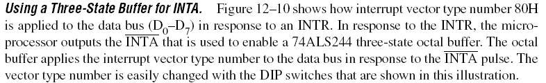
27 INT and INTA Figure 12 9 illustrates a simple circuit that applies interrupt vector type number FFH to the data bus in response to an INTR. Notice that the INTA pin is not connected in this circuit.
28
The Purpose of Interrupt
 Interrupts 3 Introduction In this chapter, the coverage of basic I/O and programmable peripheral interfaces is expanded by examining a technique called interrupt-processed I/O. An interrupt is a hardware-initiated
BASIC INTERRUPT PROCESSING
 Interrupts BASIC INTERRUPT PROCESSING This section discusses the function of an interrupt in a microprocessor-based system. Structure and features of interrupts available to Intel microprocessors. The
Chapter 12: INTERRUPTS
 Chapter 12: INTERRUPTS 12 1 BASIC INTERRUPT PROCESSING This section discusses the function of an interrupt in a microprocessor-based system. Structure and features of interrupts available to Intel microprocessors.
7/19/2013. Introduction. Chapter Objectives Upon completion of this chapter, you will be able to: Chapter Objectives 12 1 BASIC INTERRUPT PROCESSING
 Chapter 12: Interrupts Introduction In this chapter, the coverage of basic I/O and programmable peripheral interfaces is expanded by examining a technique called interrupt-processed I/O. An interrupt is
Chapter 12: Interrupts
 Chapter 12: Interrupts Introduction In this chapter, the coverage of basic I/O and programmable peripheral interfaces is expanded by examining a technique called interrupt-processed I/O. An interrupt is
An Interrupt is either a Hardware generated CALL (externally derived from a hardware signal)
") An Interrupt is either a Hardware generated CALL (externally derived from a hardware signal) OR A Software-generated CALL (internally derived from the execution of an instruction or by some other internal
An Interrupt is either a Hardware generated CALL (externally derived from a hardware signal) OR A Software-generated CALL (internally derived from the execution of an instruction or by some other internal
ECE 485/585 Microprocessor System Design
 Microprocessor System Design Lecture 3: Polling and Interrupts Programmed I/O and DMA Interrupts Zeshan Chishti Electrical and Computer Engineering Dept Maseeh College of Engineering and Computer Science
These three counters can be programmed for either binary or BCD count.
 S5 KTU 1 PROGRAMMABLE TIMER 8254/8253 The Intel 8253 and 8254 are Programmable Interval Timers (PTIs) designed for microprocessors to perform timing and counting functions using three 16-bit registers.
8086 Interrupts and Interrupt Responses:
 UNIT-III PART -A INTERRUPTS AND PROGRAMMABLE INTERRUPT CONTROLLERS Contents at a glance: 8086 Interrupts and Interrupt Responses Introduction to DOS and BIOS interrupts 8259A Priority Interrupt Controller
UMBC. contain new IP while 4th and 5th bytes contain CS. CALL BX and CALL [BX] versions also exist. contain displacement added to IP.
![UMBC. contain new IP while 4th and 5th bytes contain CS. CALL BX and CALL [BX] versions also exist. contain displacement added to IP.](/thumbs/74/70839578.jpg "UMBC. contain new IP while 4th and 5th bytes contain CS. CALL BX and CALL [BX] versions also exist. contain displacement added to IP.") Procedures: CALL: Pushes the address of the instruction following the CALL instruction onto the stack. RET: Pops the address. SUM PROC NEAR USES BX CX DX ADD AX, BX ADD AX, CX MOV AX, DX RET SUM ENDP NEAR
Procedures: CALL: Pushes the address of the instruction following the CALL instruction onto the stack. RET: Pops the address. SUM PROC NEAR USES BX CX DX ADD AX, BX ADD AX, CX MOV AX, DX RET SUM ENDP NEAR
For more notes of DAE
 Created by ARSLAN AHMED SHAAD ( 1163135 ) AND MUHMMAD BILAL ( 1163122 ) VISIT : www.vbforstudent.com Also visit : www.techo786.wordpress.com For more notes of DAE CHAPTER # 8 INTERRUPTS COURSE OUTLINE
2.5 Address Space. The IBM 6x86 CPU can directly address 64 KBytes of I/O space and 4 GBytes of physical memory (Figure 2-24).
.") Address Space 2.5 Address Space The IBM 6x86 CPU can directly address 64 KBytes of I/O space and 4 GBytes of physical memory (Figure 2-24). Memory Address Space. Access can be made to memory addresses
Address Space 2.5 Address Space The IBM 6x86 CPU can directly address 64 KBytes of I/O space and 4 GBytes of physical memory (Figure 2-24). Memory Address Space. Access can be made to memory addresses
Program Control Instructions
 Program Control Instructions Introduction This chapter explains the program control instructions, including the jumps, calls, returns, interrupts, and machine control instructions. This chapter also presents
8086 Hardware Specification
 Content: Segment 5 8086 Hardware Specification 8086 Modes of operation. Pin diagram and pin function of 8086. 8284A Clock generator operation and pin functions. Prepared By: Mohammed Abdul Kader Lecturer,
PC Interrupt Structure and 8259 DMA Controllers
 ELEC 379 : DESIGN OF DIGITAL AND MICROCOMPUTER SYSTEMS 1998/99 WINTER SESSION, TERM 2 PC Interrupt Structure and 8259 DMA Controllers This lecture covers the use of interrupts and the vectored interrupt
SRI VENKATESWARA COLLEGE OF ENGINEERING AND TECHNOLOGY DEPARTMENT OF ECE EC6504 MICROPROCESSOR AND MICROCONTROLLER (REGULATION 2013)
") SRI VENKATESWARA COLLEGE OF ENGINEERING AND TECHNOLOGY DEPARTMENT OF ECE EC6504 MICROPROCESSOR AND MICROCONTROLLER (REGULATION 2013) UNIT I THE 8086 MICROPROCESSOR PART A (2 MARKS) 1. What are the functional
SRI VENKATESWARA COLLEGE OF ENGINEERING AND TECHNOLOGY DEPARTMENT OF ECE EC6504 MICROPROCESSOR AND MICROCONTROLLER (REGULATION 2013) UNIT I THE 8086 MICROPROCESSOR PART A (2 MARKS) 1. What are the functional
Interrupts. Chapter 20 S. Dandamudi. Outline. Exceptions
 Interrupts Chapter 20 S. Dandamudi Outline What are interrupts? Types of interrupts Software interrupts Hardware interrupts Exceptions Interrupt processing Protected mode Real mode Software interrupts
6/29/2011. Introduction. Chapter Objectives Upon completion of this chapter, you will be able to:
 Chapter 6: Program Control Instructions Introduction This chapter explains the program control instructions, including the jumps, calls, returns, interrupts, and machine control instructions. This chapter
Design with Microprocessors
 Design with Microprocessors Year III Computer Science 1-st Semester Lecture 11: I/O transfer with x86 I/O Transfer I/O Instructions We discussed IN, OUT, INS and OUTS as instructions for the transfer of
Interrupts. by Rahul Patel, Assistant Professor, EC Dept., Sankalchand Patel College of Engg.,Visnagar
 Chapter 12 Interrupts by Rahul Patel, Assistant Professor, EC Dept., Sankalchand Patel College of Engg.,Visnagar Microprocessor & Interfacing (140701) Rahul Patel 1 Points to be Discussed 8085 Interrupts
2. List the five interrupt pins available in INTR, TRAP, RST 7.5, RST 6.5, RST 5.5.
 DHANALAKSHMI COLLEGE OF ENGINEERING DEPARTMENT OF ELECTRICAL AND ELECTRONICS ENGINEERING EE6502- MICROPROCESSORS AND MICROCONTROLLERS UNIT I: 8085 PROCESSOR PART A 1. What is the need for ALE signal in
MICROPROCESSOR MICROPROCESSOR ARCHITECTURE. Prof. P. C. Patil UOP S.E.COMP (SEM-II)
") MICROPROCESSOR UOP S.E.COMP (SEM-II) 80386 MICROPROCESSOR ARCHITECTURE Prof. P. C. Patil Department of Computer Engg Sandip Institute of Engineering & Management Nashik pc.patil@siem.org.in 1 Introduction
MICROPROCESSOR UOP S.E.COMP (SEM-II) 80386 MICROPROCESSOR ARCHITECTURE Prof. P. C. Patil Department of Computer Engg Sandip Institute of Engineering & Management Nashik pc.patil@siem.org.in 1 Introduction
Chapter 12. CPU Structure and Function. Yonsei University
 Chapter 12 CPU Structure and Function Contents Processor organization Register organization Instruction cycle Instruction pipelining The Pentium processor The PowerPC processor 12-2 CPU Structures Processor
Types of Interrupts:
 Interrupt structure Introduction Interrupt is signals send by an external device to the processor, to request the processor to perform a particular task or work. Mainly in the microprocessor based system
Interrupt is a process where an external device can get the attention of the microprocessor. Interrupts can be classified into two types:
 8085 INTERRUPTS 1 INTERRUPTS Interrupt is a process where an external device can get the attention of the microprocessor. The process starts from the I/O device The process is asynchronous. Classification
1 MALP ( ) Unit-1. (1) Draw and explain the internal architecture of 8085.
 Unit-1. (1) Draw and explain the internal architecture of 8085.") (1) Draw and explain the internal architecture of 8085. The architecture of 8085 Microprocessor is shown in figure given below. The internal architecture of 8085 includes following section ALU-Arithmetic
(1) Draw and explain the internal architecture of 8085. The architecture of 8085 Microprocessor is shown in figure given below. The internal architecture of 8085 includes following section ALU-Arithmetic
MICROPROCESSOR MICROPROCESSOR ARCHITECTURE. Prof. P. C. Patil UOP S.E.COMP (SEM-II)
") MICROPROCESSOR UOP S.E.COMP (SEM-II) 80386 MICROPROCESSOR ARCHITECTURE Prof. P. C. Patil Department of Computer Engg Sandip Institute of Engineering & Management Nashik pc.patil@siem.org.in 1 Introduction
MICROPROCESSOR UOP S.E.COMP (SEM-II) 80386 MICROPROCESSOR ARCHITECTURE Prof. P. C. Patil Department of Computer Engg Sandip Institute of Engineering & Management Nashik pc.patil@siem.org.in 1 Introduction
CMSC 313 COMPUTER ORGANIZATION & ASSEMBLY LANGUAGE PROGRAMMING LECTURE 09, SPRING 2013
 CMSC 313 COMPUTER ORGANIZATION & ASSEMBLY LANGUAGE PROGRAMMING LECTURE 09, SPRING 2013 TOPICS TODAY I/O Architectures Interrupts Exceptions FETCH EXECUTE CYCLE 1.7 The von Neumann Model This is a general
8085 Interrupts. Lecturer, CSE, AUST
 8085 Interrupts CSE 307 - Microprocessors Mohd. Moinul Hoque, 1 Interrupts Interrupt is a process where an external device can get the attention of the microprocessor. The process starts from the I/O device
EEL 4744C: Microprocessor Applications. Lecture 7. Part 1. Interrupt. Dr. Tao Li 1
 EEL 4744C: Microprocessor Applications Lecture 7 Part 1 Interrupt Dr. Tao Li 1 M&M: Chapter 8 Or Reading Assignment Software and Hardware Engineering (new version): Chapter 12 Dr. Tao Li 2 Interrupt An
Reading Assignment. Interrupt. Interrupt. Interrupt. EEL 4744C: Microprocessor Applications. Lecture 7. Part 1
 Reading Assignment EEL 4744C: Microprocessor Applications Lecture 7 M&M: Chapter 8 Or Software and Hardware Engineering (new version): Chapter 12 Part 1 Interrupt Dr. Tao Li 1 Dr. Tao Li 2 Interrupt An
MICROPROCESSOR ALL IN ONE. Prof. P. C. Patil UOP S.E.COMP (SEM-II)
") MICROPROCESSOR UOP S.E.COMP (SEM-II) 80386 ALL IN ONE Prof. P. C. Patil Department of Computer Engg Sandip Institute of Engineering & Management Nashik pc.patil@siem.org.in 1 Architecture of 80386 2 ARCHITECTURE
MICROPROCESSOR UOP S.E.COMP (SEM-II) 80386 ALL IN ONE Prof. P. C. Patil Department of Computer Engg Sandip Institute of Engineering & Management Nashik pc.patil@siem.org.in 1 Architecture of 80386 2 ARCHITECTURE
MICROPROCESSOR TECHNOLOGY
 MICROPROCESSOR TECHNOLOGY Assis. Prof. Hossam El-Din Moustafa Lecture 15 Ch.7 The 80386 and 80486 Microprocessors 21-Apr-15 1 Chapter Objectives Contrast the 80386 and 80486 microprocessors with earlier
MICROPROCESSOR MICROPROCESSOR. From the above description, we can draw the following block diagram to represent a microprocessor based system: Output
 8085 SATISH CHANDRA What is a Microprocessor? The word comes from the combination micro and processor. Processor means a device that processes whatever. In this context, processor means a device that processes
Microprocessor Architecture
 Microprocessor - 8085 Architecture 8085 is pronounced as "eighty-eighty-five" microprocessor. It is an 8-bit microprocessor designed by Intel in 1977 using NMOS technology. It has the following configuration
Introduction to Microprocessor
 Introduction to Microprocessor The microprocessor is a general purpose programmable logic device. It is the brain of the computer and it performs all the computational tasks, calculations data processing
CHAPTER 5 : Introduction to Intel 8085 Microprocessor Hardware BENG 2223 MICROPROCESSOR TECHNOLOGY
 CHAPTER 5 : Introduction to Intel 8085 Hardware BENG 2223 MICROPROCESSOR TECHNOLOGY The 8085A(commonly known as the 8085) : Was first introduced in March 1976 is an 8-bit microprocessor with 16-bit address
Chapter 1: Basics of Microprocessor [08 M]
![Chapter 1: Basics of Microprocessor [08 M]](/thumbs/77/75860546.jpg "Chapter 1: Basics of Microprocessor [08 M]") Microprocessor: Chapter 1: Basics of Microprocessor [08 M] It is a semiconductor device consisting of electronic logic circuits manufactured by using either a Large scale (LSI) or Very Large Scale (VLSI)
Microprocessor: Chapter 1: Basics of Microprocessor [08 M] It is a semiconductor device consisting of electronic logic circuits manufactured by using either a Large scale (LSI) or Very Large Scale (VLSI)
Lecture 5: Computer Organization Instruction Execution. Computer Organization Block Diagram. Components. General Purpose Registers.
 Lecture 5: Computer Organization Instruction Execution Computer Organization Addressing Buses Fetch-Execute Cycle Computer Organization CPU Control Unit U Input Output Memory Components Control Unit fetches
Week 11 Programmable Interrupt Controller
 Week 11 Programmable Interrupt Controller 8259 Programmable Interrupt Controller The 8259 programmable interrupt controller (PIC) adds eight vectored priority encoded interrupts to the microprocessor.
EC2304-MICROPROCESSOR AND MICROCONROLLERS 2 marks questions and answers UNIT-I
 EC2304-MICROPROCESSOR AND MICROCONROLLERS 2 marks questions and answers 1. Define microprocessors? UNIT-I A semiconductor device(integrated circuit) manufactured by using the LSI technique. It includes
Systems Programming and Computer Architecture ( ) Timothy Roscoe
 Timothy Roscoe") Systems Group Department of Computer Science ETH Zürich Systems Programming and Computer Architecture (252-0061-00) Timothy Roscoe Herbstsemester 2016 AS 2016 Exceptions 1 17: Exceptions Computer Architecture
Systems Group Department of Computer Science ETH Zürich Systems Programming and Computer Architecture (252-0061-00) Timothy Roscoe Herbstsemester 2016 AS 2016 Exceptions 1 17: Exceptions Computer Architecture
CHAPTER 6 INTERRUPT AND EXCEPTION HANDLING
 CHATER 6 INTERRUT AND EXCETION HANDLING This chapter describes the interrupt and exception-handling mechanism when operating in protected mode on an I ntel 64 or I A-32 processor. Most of the information
Description of the Simulator
 Description of the Simulator The simulator includes a small sub-set of the full instruction set normally found with this style of processor. It includes advanced instructions such as CALL, RET, INT and
1. INTRODUCTION TO MICROPROCESSOR AND MICROCOMPUTER ARCHITECTURE:
 1. INTRODUCTION TO MICROPROCESSOR AND MICROCOMPUTER ARCHITECTURE: A microprocessor is a programmable electronics chip that has computing and decision making capabilities similar to central processing unit
32- bit Microprocessor-Intel 80386
 32- bit Microprocessor-Intel 80386 30 Marks Course Outcome: Explain memory management and concept of pipelining. Describe the concept of paging and addressing. Signal Description of 80386 Signal Descriptions
MICROPROCESSOR TECHNOLOGY
 MICROPROCESSOR TECHNOLOGY Assis. Prof. Hossam El-Din Moustafa Lecture 13 Ch.6 The 80186, 80188, and 80286 Microprocessors 21-Apr-15 1 Chapter Objectives Describe the hardware and software enhancements
Intel 8086 MICROPROCESSOR. By Y V S Murthy
 Intel 8086 MICROPROCESSOR By Y V S Murthy 1 Features It is a 16-bit μp. 8086 has a 20 bit address bus can access up to 2 20 memory locations (1 MB). It can support up to 64K I/O ports. It provides 14,
MACHINE CONTROL INSTRUCTIONS: 1. EI
 Lecture-33 MACHINE CONTROL INSTRUCTIONS: 1. EI (Enable interrupts): The interrupt system is disabled just after RESET operation. There is an internal INTE F/F (Interrupt enable flipflop) which is reset
Overview of Intel 80x86 µp
 CE444 ١ ٢ 8088/808 µp and Supporting Chips Overview of Intel 80x8 µp ٢ ١ 8088/808 µp ٣ Both are mostly the same with small differences. Both are of bit internal Data bus Both have 0 bit address bus Capable
UNIT II OVERVIEW MICROPROCESSORS AND MICROCONTROLLERS MATERIAL. Introduction to 8086 microprocessors. Architecture of 8086 processors
 OVERVIEW UNIT II Introduction to 8086 microprocessors Architecture of 8086 processors Register Organization of 8086 Memory Segmentation of 8086 Pin Diagram of 8086 Timing Diagrams for 8086 Interrupts of
1. state the priority of interrupts of Draw and explain MSW format of List salient features of
 Q.1) 1. state the priority of interrupts of 80286. Ans- 1. Instruction exceptions 2. Single step 3. NMI 4. Processor extension segment overrun 5. INTR 6. INT 2. Draw and explain MSW format of 80286. Ans-
1. Internal Architecture of 8085 Microprocessor
 1. Internal Architecture of 8085 Microprocessor Control Unit Generates signals within up to carry out the instruction, which has been decoded. In reality causes certain connections between blocks of the
 UNIT II SYSTEM BUS STRUCTURE 1. Differentiate between minimum and maximum mode 2. Give any four pin definitions for the minimum mode. 3. What are the pins that are used to indicate the type of transfer
MICROPROCESSOR PROGRAMMING AND SYSTEM DESIGN
 MICROPROCESSOR PROGRAMMING AND SYSTEM DESIGN ROAD MAP SDK-86 Intel 8086 Features 8086 Block Diagram 8086 Architecture Bus Interface Unit Execution Unit 8086 Architecture 8086 Programmer s Model Flag Register
Basics of Microprocessor
 Unit 1 Basics of Microprocessor 1. Microprocessor Microprocessor is a multipurpose programmable integrated device that has computing and decision making capability. This semiconductor IC is manufactured
EC 6504 Microprocessor and Microcontroller. Unit II System Bus Structure
 EC 6504 Microprocessor and Microcontroller Unit II 8086 System Bus Structure Syllabus: 8086 Signals Basic Configurations System bus timing System Design using 8086 IO Programming Introduction to multiprogramming
8086 INTERNAL ARCHITECTURE
 8086 INTERNAL ARCHITECTURE Segment 2 Intel 8086 Microprocessor The 8086 CPU is divided into two independent functional parts: a) The Bus interface unit (BIU) b) Execution Unit (EU) Dividing the work between
Chapter 8 PC Peripheral Chips - Pt 3 Interrupts
 Chapter 8 PC Peripheral Chips - Pt 3 Interrupts PC Architecture for Technicians: Level-1 Systems Manufacturing Training and Employee Development Copyright 1996 Intel Corp. Ch 8 - Page 1 OBJECTIVES: AT
Mechanisms for entering the system
 Mechanisms for entering the system Yolanda Becerra Fontal Juan José Costa Prats Facultat d'informàtica de Barcelona (FIB) Universitat Politècnica de Catalunya (UPC) BarcelonaTech 2017-2018 QP Content Introduction
Moodle WILLINGDON COLLEGE SANGLI (B. SC.-II) Digital Electronics
 Digital Electronics") Moodle 4 WILLINGDON COLLEGE SANGLI (B. SC.-II) Digital Electronics Advanced Microprocessors and Introduction to Microcontroller Moodle developed By Dr. S. R. Kumbhar Department of Electronics Willingdon
Moodle 4 WILLINGDON COLLEGE SANGLI (B. SC.-II) Digital Electronics Advanced Microprocessors and Introduction to Microcontroller Moodle developed By Dr. S. R. Kumbhar Department of Electronics Willingdon
INTRO TO I/O INTERFACE
 Basic I/O Interface Introduction This chapter outlines some of the basic methods of communications, both serial and parallel, between humans or machines and the microprocessor. We first introduce the basic
Chapter 2 COMPUTER SYSTEM HARDWARE
 Chapter 2 COMPUTER SYSTEM HARDWARE A digital computer system consists of hardware and software. The hardware consists of the physical components of the system, whereas the software is the collection of
Processor Structure and Function
 WEEK 4 + Chapter 14 Processor Structure and Function + Processor Organization Processor Requirements: Fetch instruction The processor reads an instruction from memory (register, cache, main memory) Interpret
Summer 2003 Lecture 21 07/15/03
 Summer 2003 Lecture 21 07/15/03 Simple I/O Devices Simple i/o hardware generally refers to simple input or output ports. These devices generally accept external logic signals as input and allow the CPU
MICROPROCESSOR TECHNOLOGY
 MICROPROCESSOR TECHNOLOGY Assis. Prof. Hossam El-Din Moustafa Lecture 5 Ch.2 A Top-Level View of Computer Function (Cont.) 24-Feb-15 1 CPU (CISC & RISC) Intel CISC, Motorola RISC CISC (Complex Instruction
 Question Bank Part-A UNIT I- THE 8086 MICROPROCESSOR 1. What is microprocessor? A microprocessor is a multipurpose, programmable, clock-driven, register-based electronic device that reads binary information
eaymanelshenawy.wordpress.com
 Lectures on Memory Interface Designed and Presented by Dr. Ayman Elshenawy Elsefy Dept. of Systems & Computer Eng.. Al-Azhar University Email : eaymanelshenawy@yahoo.com eaymanelshenawy.wordpress.com Lecture
9/25/ Software & Hardware Architecture
 8086 Software & Hardware Architecture 1 INTRODUCTION It is a multipurpose programmable clock drive register based integrated electronic device, that reads binary instructions from a storage device called
Control Unit: The control unit provides the necessary timing and control Microprocessor resembles a CPU exactly.
 Unit I 8085 and 8086 PROCESSOR Introduction to microprocessor A microprocessor is a clock-driven semiconductor device consisting of electronic logic circuits manufactured by using either a large-scale
Sunday, April 25, 2010
 Sunday, April 25, 2010 BSNL TTA EXAM MICRO PROCESSER BSNL TTA EXAM MICRO PROCESSER 1. A 32-bit processor has (a) 32 registers (b) 32 I/O devices (c) 32 Mb of RAM (d) a 32-bit bus or 32-bit registers 2.
Microcomputer System Design
 Microcomputer System Design COE305 Lab. What is a Microprocessor? A microprocessor is a multipurpose, clockdriven, register-based electronic device that reads binary instructions from a storage device
The K Project. Interrupt and Exception Handling. LSE Team. May 14, 2018 EPITA. The K Project. LSE Team. Introduction. Interrupt Descriptor Table
 and Exception Handling EPITA May 14, 2018 (EPITA) May 14, 2018 1 / 37 and Exception Handling Exception : Synchronous with program execution (e.g. division by zero, accessing an invalid address) : Asynchronous
VARDHAMAN COLLEGE OF ENGINEERING (AUTONOMOUS) Shamshabad, Hyderabad
 Shamshabad, Hyderabad") Introduction to MS-DOS Debugger DEBUG In this laboratory, we will use DEBUG program and learn how to: 1. Examine and modify the contents of the 8086 s internal registers, and dedicated parts of the memory
Introduction to MS-DOS Debugger DEBUG In this laboratory, we will use DEBUG program and learn how to: 1. Examine and modify the contents of the 8086 s internal registers, and dedicated parts of the memory
EC6504 MICROPROCESSOR AND MICROCONTROLLER
 UNIT I THE 8086 MICROPROCESSOR 1. What do you mean by Addressing modes? (May/June 2014) The different ways that a microprocessor can access data are referred to as addressing modes. 2. What is meant by
MICROPROCESSOR TECHNOLOGY
 MICROPROCESSOR TECHNOLOGY Assis. Prof. Hossam El-Din Moustafa Lecture 17 Ch.8 The Pentium and Pentium Pro Microprocessors 21-Apr-15 1 Chapter Objectives Contrast the Pentium and Pentium Pro with the 80386
Intel 8086 MICROPROCESSOR ARCHITECTURE
 Intel 8086 MICROPROCESSOR ARCHITECTURE 1 Features It is a 16-bit μp. 8086 has a 20 bit address bus can access up to 2 20 memory locations (1 MB). It can support up to 64K I/O ports. It provides 14, 16
William Stallings Computer Organization and Architecture 10 th Edition Pearson Education, Inc., Hoboken, NJ. All rights reserved.
 + William Stallings Computer Organization and Architecture 10 th Edition 2016 Pearson Education, Inc., Hoboken, NJ. All rights reserved. 2 + Chapter 14 Processor Structure and Function + Processor Organization
EEE3410 Microcontroller Applications Department of Electrical Engineering Lecture 4 The 8051 Architecture
 Department of Electrical Engineering Lecture 4 The 8051 Architecture 1 In this Lecture Overview General physical & operational features Block diagram Pin assignments Logic symbol Hardware description Pin
CS 550 Operating Systems Spring Interrupt
 CS 550 Operating Systems Spring 2019 Interrupt 1 Revisit -- Process MAX Stack Function Call Arguments, Return Address, Return Values Kernel data segment Kernel text segment Stack fork() exec() Heap Data
QUESTION BANK. EE 6502 / Microprocessor and Microcontroller. Unit I Processor. PART-A (2-Marks)
") QUESTION BANK EE 6502 / Microprocessor and Microcontroller Unit I- 8085 Processor PART-A (2-Marks) YEAR/SEM : III/V 1. What is meant by Level triggered interrupt? Which are the interrupts in 8085 level
QUESTION BANK EE 6502 / Microprocessor and Microcontroller Unit I- 8085 Processor PART-A (2-Marks) YEAR/SEM : III/V 1. What is meant by Level triggered interrupt? Which are the interrupts in 8085 level
Pin diagram Common SignalS Architecture: Sub: 8086 HARDWARE
 1 CHAPTER 6 HARDWARE ARCHITECTURE OF 8086 8086 Architecture: 6.1 8086 Pin diagram 8086 is a 40 pin DIP using CHMOS technology. It has 2 GND s as circuit complexity demands a large amount of current flowing
Pin Description, Status & Control Signals of 8085 Microprocessor
 Pin Description, Status & Control Signals of 8085 Microprocessor 1 Intel 8085 CPU Block Diagram 2 The 8085 Block Diagram Registers hold temporary data. Instruction register (IR) holds the currently executing
EC-333 Microprocessor and Interfacing Techniques
 EC-333 Microprocessor and Interfacing Techniques Lecture 3 The Microprocessor and its Architecture Dr Hashim Ali Fall - 2018 Department of Computer Science and Engineering HITEC University Taxila Slides
Vidyalankar. Vidyalankar T.E. Sem. V [CMPN] Microprocessors Prelim Question Paper Solution. 1. (a)
![Vidyalankar. Vidyalankar T.E. Sem. V [CMPN] Microprocessors Prelim Question Paper Solution. 1. (a)](/thumbs/85/91719469.jpg "Vidyalankar. Vidyalankar T.E. Sem. V [CMPN] Microprocessors Prelim Question Paper Solution. 1. (a)") 1. (a) Step 1 : Total EPROM required Chip size available No.of chips required = 2 T.E. Sem. V [CMPN] Microprocessors Prelim Question Paper Solution = 64 KB = 32 KB No.of sets required = 2 1 2 Set 1 = Ending
1. (a) Step 1 : Total EPROM required Chip size available No.of chips required = 2 T.E. Sem. V [CMPN] Microprocessors Prelim Question Paper Solution = 64 KB = 32 KB No.of sets required = 2 1 2 Set 1 = Ending
CPU Structure and Function
 Computer Architecture Computer Architecture Prof. Dr. Nizamettin AYDIN naydin@yildiz.edu.tr nizamettinaydin@gmail.com http://www.yildiz.edu.tr/~naydin CPU Structure and Function 1 2 CPU Structure Registers
In 8086 Carry flag, Parity flag, Auxiliary carry flag, Zero flag, Overflow flag, Trace flag, Interrupt flag, Direction flag, and Sign flag.
 What is a Microprocessor? Microprocessor is a program-controlled device, which fetches the instructions from memory, decodes and executes the instructions. Most Micro Processor are single- chip devices.
Chapter 1. Microprocessor architecture ECE Dr. Mohamed Mahmoud.
 Chapter 1 Microprocessor architecture ECE 3130 Dr. Mohamed Mahmoud The slides are copyright protected. It is not permissible to use them without a permission from Dr Mahmoud http://www.cae.tntech.edu/~mmahmoud/
Instructions Involve a Segment Register (SR-field)
") BYTE 1 = 11000111 2 = C7 16 BYTE 2 = (MOD)000(R/M) = 100000112 = 83 16 BYTE 3 = 34 16 and BYTE 4 = 12 16 BYTE 5 = CD 16 and BYTE 6 = AB 16 The machine code for the instruction is: MOV [BP+DI+1234H], 0ABCDH
BYTE 1 = 11000111 2 = C7 16 BYTE 2 = (MOD)000(R/M) = 100000112 = 83 16 BYTE 3 = 34 16 and BYTE 4 = 12 16 BYTE 5 = CD 16 and BYTE 6 = AB 16 The machine code for the instruction is: MOV [BP+DI+1234H], 0ABCDH
Module Introduction. PURPOSE: The intent of this module is to explain MCU processing of reset and interrupt exception events.
 Module Introduction PURPOSE: The intent of this module is to explain MCU processing of reset and interrupt exception events. OBJECTIVES: - Describe the difference between resets and interrupts. - Identify
UNIT-I. 1.Draw and explain the Architecture of a 8085 Microprocessor?
 UNIT-I INTRODUCTION TO MICROPROCESSOR A common way of categorizing microprocessors is by the no. of bits that their ALU can work with at a time. (i) The first commercially available microprocessor was
Chapter 13 Direct Memory Access and DMA-Controlled I/O
 Chapter 13 Direct Memory Access and DMA-Controlled I/O The DMA I/O technique provides direct access to the memory while the microprocessor is temporarily disabled This allows data to be transferred between
8/26/2010. Introduction to 8085 BLOCK DIAGRAM OF INTEL Introduction to Introduction to Three Units of 8085
 BLOCK DIAGRAM OF INTEL 8085 GURSHARAN SINGH TATLA Introduction to 8085 It was introduced in 1977. It is 8-bit microprocessor. Its actual name is 8085 A. It is single NMOS device. It contains 6200 transistors
Exception Handling. Precise Exception Handling. Exception Types. Exception Handling Terminology
 Precise Handling CprE 581 Computer Systems Architecture Reading: Textbook, Appendix A Handling I/O Internal s Arithmetic overflow Illegal Instruction Memory Address s Protection violation Data alignment
Lecture (02) The Microprocessor and Its Architecture By: Dr. Ahmed ElShafee
 The Microprocessor and Its Architecture By: Dr. Ahmed ElShafee") Lecture (02) The Microprocessor and Its Architecture By: Dr. Ahmed ElShafee ١ INTERNAL MICROPROCESSOR ARCHITECTURE Before a program is written or instruction investigated, internal configuration of the
Lecture (02) The Microprocessor and Its Architecture By: Dr. Ahmed ElShafee ١ INTERNAL MICROPROCESSOR ARCHITECTURE Before a program is written or instruction investigated, internal configuration of the
Memory & Simple I/O Interfacing
 Chapter 10 Memory & Simple I/O Interfacing Expected Outcomes Explain the importance of tri-state devices in microprocessor system Distinguish basic type of semiconductor memory and their applications Relate
3. The MC6802 MICROPROCESSOR
 3. The MC6802 MICROPROCESSOR This chapter provides hardware detail on the Motorola MC6802 microprocessor to enable the reader to use of this microprocessor. It is important to learn the operation and interfacing
12-Dec-11. Gursharan Singh Maninder Kaur. Introduction to 8085 BLOCK DIAGRAM OF INTEL Introduction to Introduction to 8085
 mailme@gursharansingh.in BLOCK DIAGRAM OF INTEL 8085 mailme@maninderkaur.in Introduction to 8085 It was introduced in 1977. It is 8-bit microprocessor. Its actual name is 8085 A. It is single NMOS device.
UNIT- 5. Chapter 12 Processor Structure and Function
 UNIT- 5 Chapter 12 Processor Structure and Function CPU Structure CPU must: Fetch instructions Interpret instructions Fetch data Process data Write data CPU With Systems Bus CPU Internal Structure Registers