FiberExpress Brilliance Connectors
|
|
|
- Spencer Lewis
- 6 years ago
- Views:
Transcription


1 FiberExpress Brilliance Connectors Installation Guide PX105234
2 Table of Contents Section A - What s New and What You Need to Know 02 Section B - Components and Features 04 Section C - Fiber Preparation 07 Section D - Installation on 900 μm Fiber 09 Section E - Installation on 900 μm Fiber Using Accessories 11 Section F - Installation on 250 μm Fiber Using 900 μm Breakout Kit 15 Section G - Installation on Jacketed Fiber 17 Section H - Cleaning Procedures 21 Section I - Troubleshooting Guide and Tips 22 Information subject to change without notice. Belden reserves the right to make changes in product design or components as progress in engineering or manufacturing may warrant. FiberExpress Brilliance is a trademark of Belden, Inc Belden, Inc. All Rights Reserved. Printed in Canada FiberExpress Brilliance Connector - Installation Guide Page 1


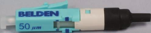
3 Section A - What s New and What You Need to Know FiberExpress Brilliance Connectors Include: Brilliance OM μm, OM2 and OM3/OM4 50 μm Multimode & OS2 Singlemode Connectors. ST Connector SC Connector LC Connector Dust Cap** ST Activator Cap FRONT Color Coded Connector Body LC Latch Activator Tab Rear Housing REAR 900 μm Boot Dust Cap Fiber Type VFL* Light Window Small Indicator Line Large Indicator Line * Visual Fault Locator ** The ST connector s dust cap is not held by the ferrule but instead locks to the connector body. This connector also includes an ST Activator Cap. Brilliance LC, SC and ST connectors all share the same component names shown above. The LC connector is used throughout this guide as a reference only. Open Position Closed Position Standard Release F February 2012 Page 2


4 Section A - What s New and What You Need to Know This Guide Includes: Installation procedures for Brilliance LC, SC and ST connectors. A section describing components, features and accessories. Cleaning procedures. A troubleshooting guide and tips. LASER RADIATION CAUTION: When installed on a live system, invisible laser radiation may be present. Do not stare into connector endface or view directly with optical instruments. Wear safety glasses when working with optical fiber. Dispose of all scrap fiber in the waste bottle to avoid getting fiber slivers. Do not touch cleaver blade. Key Success Parameters Cleanliness: - Keep exposed fiber components clean as well as your environment. - Keep dust caps on and avoid dust creating activities. - Clean endface with alcohol wipes and then dry wipe as per cleaning procedures Cleave Quality: - Field cleaver can produce inconsistant results, verify cleave quality with a microscope after each cleave. - Precision cleavers are recommended and will improve cleave quality. However, it is important to validate cleaver performance every 25 connectors or less. Installation Quality: - Test connector performance at every 100 connector installations or less. - Use VFL and Support Handle for best results during termination. FiberExpress Brilliance Connector - Installation Guide Page 3


 1 2 Lid Zipper Velcro Lid")

5 Section B - Components and Features Shoulder Strap x 11 Letter Size Zipper Pocket Belt Mount Feature Support Handle Holster 2 (See Page 6 for details on Support Handle) 1 2 Lid Zipper Velcro Lid Strap 3 3 Zipper Pocket for Loose Items Business Card Sleeve Standard Release F February 2012 Page 4

6 Section B - Components and Features Support Handle 2. Protective Adapter 3. SC Adapter 4. LC Adapter 5. ST Adapter 6. Patch Cords 7. Field Cleaver 8. Precision Cleaver 9. Alcohol Wipes 10. Waste Bottle 11. Safety Glasses 12. Multipurpose Strippers 13. Scissors 14. Tweezers 15. USB Key with Demo Video & Files 16. Ink Marker 17. Visual Fault Locator (VFL) 18. Microscope 19. Installation Guide 20. Installation Cards FiberExpress Brilliance Connector - Installation Guide Page 5


7 Section B - Components and Features Precision Cleaver Precision Cleaver 1. Cleaver Lock 2. Cleave Arming Button 3. Fiber Guide 4. Buffer Stopper 5. Visual Guide 6. Blade Field Cleaver Field Cleaver 13. Blade 14. Grip Lever 15. Fiber Tip Grip 16. Graduated Scale 17. Flexible Fiber Guide Support Handle Support Handle 7. VFL Push-out Access 8. Handle Grip 9. Fiber Groove Guide 10. Stylus Holder 11. Stylus 12. Support Handle Adapter Clips Microscope Microscope 18. Fiber Cover 19. Fiber Buffer Guide 20. Fiber Target 21. Light Window 22. Light On/Off Toggle (Optional) 23. Focus Adjustment Wheel 24. Viewer 25. Pull-out Magnifier Standard Release F February 2012 Page 6


8 Section C - Fiber Preparation Fiber Preparation on 900 μm Tight Buffered Fiber 1 Slide the boot on the fiber as shown. 2 Strip off the buffer and the glass coating at the length specified below: a. Field cleaver: 40 mm b. Precision cleaver: 24 ± 2 mm. If unfamiliar with stripping optical fiber, it is advised to practice using a spare piece of fiber. Be sure to remove in small sections (5 mm) to avoid breaking the fiber. 3 Align the buffer on the Installation Card s graduated scale and mark with an ink marker at 13 mm. 1 Install Boot on Fiber 2 Strip Buffer and Coating from Fiber 3 Mark Buffer at 13 mm FiberExpress Brilliance Connector - Installation Guide Page 7


9 Section C - Fiber Preparation Fiber Preparation on 900 μm Tight Buffered Fiber (Continued) 4 Clean the bare fiber with alcohol wipes. Use at least two or three passes while protecting the buffer mark with your fingers. Avoid contaminating the bare fiber once it has been cleaned Cleave the fiber at 8 mm from buffer. When using our precision cleaver, bring the buffer in contact with the cleaver buffer stop. Be sure to read and understand the cleaver instructions before use. Validate cleaver's performance prior to first termination, afterwards re-validate every 25. Use a microscope or another appropriate device to verify cleave quality as per figure 6. Note: Do not clean the fiber after it has been cleaved. 6 If you are not using a precision cleaver*, it is strongly recommended to verify cleave angle and cleanliness with a microscope for every cleave. Cleave quality depends on the skill of the operator Clean Fiber 5 Cleave fiber at 8 mm 6 Verify Cleave * -0.0 * Important: See "Key Success Parameters" in Section A - What's New and What You Need to Know. Standard Release F February 2012 Page 8


.")
10 Section D - Installation on 900 μm Fiber Basic Installation 1 Push the activator tab towards the front of the connector using the small line indicator as a locating reference.* A stylus and Support Handle available if needed to provide assistance in opening and closing the activator tab. 2 Align the fiber tip with the rear housing by bringing both hands together for stability, as shown. Guide the fiber into the connector until you reach the buffer mark. Note: Secure the connector by placing your index finger on the ferrule dust cap while gripping the two sides as shown, especially with SC type connectors. Otherwise, an adapter is available with the Installation Kit to help grip the connector (see Section B). * For ST connectors, ensure the Dust Cap is in place and the ST Activator Cap is removed to gain access to the Activator Tab. 1 Open Activator Tab Alternative: Using Stylus 2 Insert Fiber into Connector FiberExpress Brilliance Connector - Installation Guide Page 9


11 Section D - Installation on 900 μm Fiber Basic Installation (Continued) 3a Use your dominant hand to produce a bow in the fiber. Hold the bow in place with the fingers from your dominant hand while leaving your index free, as shown. Pull the activator tab towards the rear, using the large line indicator as a locating reference. 3b Use your dominant hand to produce a bow in the fiber. Secure the bow with your passive hand while holding the connector as shown. Use your free hand to pull the activator tab towards the rear, using the large indicator line as a locating reference. 4 Install the connector boot by sliding it onto the rear of the connector until it reaches the body.* The installation is now complete. * For ST connectors, re-install the ST Activator Cap. Note: For best results, Belden recommends the use of the Support Handle and VFL. 3a Activation Method 1 3b Activation Method 2 4 Install Boot Standard Release F February 2012 Page 10


12 Section E - Installation on 900 μm Fiber Using Accessories 1 Support Handle Preparation 1.1 Remove the clip protector and insert the appropriate adapter into the Support Handle as shown. 1.2 If you are using a Visual Fault Locator (VFL), first remove the VFL s protective cap then snap the VFL into the Support Handle as shown. Using a VFL is optional. 1.3 Connect the VFL to the adapter using the appropriate supplied patch cord. Note: For APC connectors use an APC VFL patch cord and APC adapter, sold seperately (AX203895). For Standard connectors use a UPC VFL patch cord and standard adapter. Damage may occur if APC is mated to a flat ferrule. 1.1 Snap in Adapter 1.2 Snap in VFL 1.3 Connect Patch Cord FiberExpress Brilliance Connector - Installation Guide Page 11


13 Section E - Installation on 900 μm Fiber Using Accessories 1 Support Handle Preparation (Continued) 1.4 Insert the Brilliance connector into the Support Handle s adapter as shown. 1.5 Arm the VFL, then choose a pulse or continuous laser mode by repeatedly pressing the mode toggle button. A green light will appear to indicate that the VFL is active. If a red light appears, the batteries need to be replaced. 1.6 Push connector activator tab towards the front of the connector using the small line indicator as locating reference.* A stylus is available in the Support Handle, if needed, to provide assistance in opening and closing the activator tab. 1.7 When using a VFL in the connection process, a red light will appear in the connector window. * For ST connectors, first ensure the ST Activator Cap is removed. 1.5 Turn on VFL 1.6 Open Activator 1.7 Light Indicator Mode Toggle Button Arming Button Standard Release F February 2012 Page 12


14 Section E - Installation on 900 μm Fiber Using Accessories 2 Fiber Preparation (See Section C for steps) The support handle can be placed in the pouch s exterior holster or on a work surface to be ready for use while preparing the fiber. 3 Insert Fiber 3.1 After preparing the fiber, grip the Support Handle with your passive hand. 3.2 Using your dominant hand, guide the fiber into the Support Handle groove. Allow the fiber to follow the curve in the handle and secure it with your thumb. 3.3 Guide the fiber into the connector and stop when you feel contact. When fully inserted, the buffer mark should be near the edge of the rear housing of the Brilliance connector. If not, gently back off and reseat the fiber. 3.1 Grip Support Handle 3.2 Place Fiber in Groove 3.3 Insert Fiber FiberExpress Brilliance Connector - Installation Guide Page 13


15 Section E - Installation on 900 μm Fiber Using Accessories 4 Finalize Connector Installation 4.1 Produce a bow by sliding your thumb along the Support Handle s graduated scale. Slide between 5 and 8 mm to produce a slight bow as shown and use your thumb to hold the fiber in position. 4.2 Use your other hand to pull the connector activator tab towards the rear using the large indicator line as a locating reference. Once the activator is closed and when using a VFL, the red light in the VFL window should go out for MM connectors or dim substantially for SM connectors, as shown. If not repeat fiber preparation steps and try again. 4.3 Install the connector boot, slide it onto the rear of the connector until it reaches the body.* Remove the connector from support handle.the installation is now complete. * For ST connectors, re-install the ST Activator Cap. 4.1 Produce Bow 4.2 Close Activator 4.3 Install Boot MM SM Standard Release F February 2012 Page 14


16 Section F - Installation on 250 μm Fiber Using 900 μm Breakout Kit Breakout Kit Preparation Refer to Breakout Kit Installation Guide provided with each AX or AX for breakout kit installation on loose tube or mini distribution cables. 1 Slide the boot on the fiber as shown. 2 Using the 250 µm region of the stripper, strip off the buffer at the length specified below: a. Field cleaver: 40 mm b. Precision cleaver: 24 ± 2 mm. 3 Gently push the fiber back into the tube. 1 Install Boot on Fiber 2 Strip Off Tube 3 Push Fiber Back In FiberExpress Brilliance Connector - Installation Guide Page 15


17 Section F - Installation on 250 μm Fiber Using 900 μm Breakout Kit Breakout Kit Preparation (Continued) 4 Using the 125 μm region of the stripper, remove 250 μm coating from the tube to the fiber s end. 5 Align the tube on the Installation Card s graduated scale and mark with the ink marker at 13 mm. 6 Thoroughly clean the bare fiber with an alcohol wipe and gently push the fiber back into the tube. 7 Refer to Section C: Step 5 for cleaving instructions and Section D or E to complete the installation. 5 Make Mark at 13 mm 6 Clean Bare Fiber 7 Cleave fiber at 8 mm Standard Release F February 2012 Page 16


18 Section G - Installation on Jacketed Fiber 1 Support Handle Preparation Refer to Section E - Steps 1.1 through Fiber Preparation 2.1 Ensure the cable is freshly cut or that all the layers are of equal length. Then apply two marks at the following lengths: a. If using a Field Cleaver: First mark at 45 mm then a second mark add 60 mm from the end of the cable. b. If using a Precision Cleaver: First mark at 29±2 mm then add second mark at 44 mm from the end of the cable. 2.2 Remove the cable jacket from the first mark using the stripper diameter furthest from the grip, as shown. 2.3 Use the scissors to cut the kevlar off flush with the end of the jacket. 2.4 Use the stippers to create a small break in the jacket at second mark, then remove the section with your fingers. 2.2 Remove Jacket from First Mark 2.3 Cut Off Kevlar 2.4 Remove from Second Mark with Fingers FiberExpress Brilliance Connector - Installation Guide Page 17


19 Section G - Installation on Jacketed Fiber 2 Fiber Preparation (continued) Quick Reference Diagram (lengths to scale) 2.5 Twist the boot onto the cable and slide it about 30 cm down. 2.6 Gently hold the jacket and push the 900 µm buffer as far into the cable as possible. 2.7 Hold the kevlar out of the way and mark the 900 µm buffer at the end of the jacket, at 7 mm and finally at 20 mm, as shown on right. 2.8 Wrap the cable twice, tightly, around two fingers and strip off the 900 µm buffer and coating from the 20 mm mark. Be sure to remove the buffer in small sections (5 mm) to avoid breaking it. Field Cleaver Precision Cleaver Jacket 15 mm 45 mm 15 mm mm 20 mm 15 mm 7 mm Buffer Fiber 2.5 Insert Boot 2.6 Push Fiber into Cable 2.8 Strip 900 µm Buffer from 20mm Mark Standard Release F February 2012 Page 18


20 Section G - Installation on Jacketed Fiber 2 Fiber Preparation (continued) 2.9 Clean the bare fiber with alcohol wipes, use at least two passes. Avoid contaminating the bare fiber once it has been cleaned Cleave the bare fiber at 8 mm from buffer s end. When using our precision cleaver, bring the buffer in contact with the cleaver stopper. Be sure to read and understand the cleaver instructions before use. Note: Do not clean the fiber after it has been cleaved. 3 Fiber Installation Using a Support Handle for fiber installation is strongly recommended. a. If using a Support Handle: Refer to Section E - Steps 3.1 through 4.2, then unclip the connector to relieve mating pressure, but leave it in the adapter. b. If installing freehand: Refer to Section D - Steps 1.1 to Clean Bare Fiber 2.10 Cleave fiber at 8 mm 3 a. Unclip Connector -0.0 FiberExpress Brilliance Connector - Installation Guide Page 19


21 Section G - Installation on Jacketed Fiber 4 Jacket Installation 4.1 Verify that the buffer mark at the end of the jacket is still at the same place. If not, push the buffer back in. Then evenly distribute the kevlar around the connector and bring the boot close to the connector, as shown. 4.2 Create a bow: a. If using a Support Handle: Slide the cable 3 mm along the Support Handle groove to create a slight bow. b. If installing freehand: Create a bow using the technique shown in Section D - Step 1.3b 4.3 While maintaining the bow created in the previous step, screw on the boot until a resistance is felt, do not apply any force during this step. 4.4 Hold the connector in your hands and add approximately a ¼ turn or 5 clicks to lock it. Locking feedback may vary when using 3 mm jacketed fiber. 4.5 Remove the connector from the Support Handle. The installation is now complete. 4.2 Slide 3 mm to Create Slight Bow 4.3 Screw on Boot Until it Blocks 4.4 Apply a ¼ turn or 5 clicks to lock 3 mm Standard Release F February 2012 Page 20
22 Section H - Cleaning Procedures Connector Cleaning Procedure and Precautions 1. Wipe the connector ferrule end-face a few times with a lint-free alcohol soaked wipe. 2. Before the alcohol has time to dry, wipe the ferrule end-face with a dry wipe to remove any residual alcohol. * Do not allow ferrule to touch anything before inserting into adapter. * Preferred alcohol is ethanol but isopropyl alcohol may be used. Only 100% pure alcohol should be used. VFL Components Cleaning Procedure and Precautions 1. Remove the patch cord and clean the connector ferrule at both ends as described above. 2. Ensure the interior of the VFL adapters are free of contaminants. 3. Ensure the interior of VFL ferrule sleeve is free of contaminants. If not, a lint-free swab can be used to dislodge and remove contaminents. 4. Reapply dust caps to patch cord and adapters immediately after use. Tips 1. When cleaning the bare fiber with alcohol wipes, a squeak is a good indication that the fiber is free of impurities. 2. Clean the patch cords and adapters regularly by following the recommended procedure. If a contaminant adheres to the ferrule tip or adapter ferrule guide, each connector installed could be damaged or contaminated. 3. It is strongly recommended to store unused adapters in a clean package such as the original packaging to avoid adapter contamination. FiberExpress Brilliance Connector - Installation Guide Page 21
23 Section I - Troubleshooting Guide and Tips Connector Troubleshooting 1. If the VFL is still visible in the connector window after terminating or test results are marginal: - The cleave may not be good. Ensure the cleaver is in good working order (see cleaver instructions, FiberExpress Brilliance connectors Installation Guide Section C - step 5-6 and Section A - Key Success Parameters) then repeat the cleave and termination procedure. - The cleaved fiber tip may be dirty. Ensure work area is clean and repeat cleave and termination procedure. If the problem persists contaminants may have been introduced into the connector. 2. If you cannot insert the fiber up to the buffer mark, make sure your mark and cleave are accurate and that the connector activator tab is in the open position, then repeat the termination procedure. 3. If the fiber breaks inside the connector, discard the unusable connector and repeat the procedure. Tips A - When removing the buffer from the fiber, cut perpendicular to the fiber and then tilt the stripper slightly to facilitate removal. B - When a field cleaver is used, it is strongly recommended to verify the cleave quality with a microscope. C - If a VFL and patch cord are attached to the Support Handle be sure not to crush the patch cord in the interior pocket of the pouch. Instead, use the exterior holsters while working. After use, it is recommended to remove the patch cord and adapter then reinstall the appropriate dust caps. D - A stylus included in the Support Handle can be used instead of your nail to push the activator tab. E - Turn off the VFL after every use to extend the life of the batteries. F - Make sure the dust caps are not installed when removing the adapter from the support handle. G - To ensure the VFL is properly fastened to the Support Handle make sure a snap is heard while attaching it to the Support Handle. H - If the light from the VFL is not apparent in the Brilliance connector window while in the open position, try closing and reopening the activator tab. I - To remove the VFL from the Support Handle press on the VFL through the Support Handle Push-out Pocket located in front of the adapter clipping location. Standard Release F February 2012 Page 22
24 PX For more information on Belden products, please call: U.S.A. & Canada BELDEN1 ( ) For a list of regional sales offices visit our WEB SITE: Belden, Inc. All rights reserved. Printed in Canada Document release: F Date:February 2012 Order Number: AX104273
Product Bulletin PB 308
 Product Bulletin PB 308 FiberExpress Brilliance Field-Installable Connectors Brilliant in design and implementation, FiberExpress Brilliance Field-installable Connectors make fiber termination simple and
3M Fibrlok II Angle Fiber Splice 2529-AS 3M Fibrlok 250 µm Angle Fiber Splice 2540-AS
 3M Fibrlok II Angle Fiber Splice 2529-AS 3M Fibrlok 250 µm Angle Fiber Splice 2540-AS Instructions January 2009 78-8140-1580-2-C Contents 1.0 Summary...3 2.0 Splicing Set-up...4 3.0 Fiber Preparation...4
Crimplok ST* and SC Non-Adhesive Fiber Optic Single & Multi-mode Connectors
 Crimplok ST* and SC Non-Adhesive Fiber Optic Single & Multi-mode Connectors Instructions July 2002 78-8073-7660-9-F 1 Contents 1.0 Warnings and Recommendations... 3 2.0 Tool Kit Contents... 4 3.0 Termination...
Product Data Sheet. SC Thead-Lock Connector Assembly Instructions. Page 1 of 5 QUALITY FIBER COMPONENTS, EQUIPMENT, & SUPPLIES
 Page 1 of 5 SC Thead-Lock Connector Assembly Instructions Page 2 of 5 A. 2.0mm, 2.5mm & 3.0mm JACKETED CABLE 1. Place jacketed fiber protective boot on cable and slide back. (Figure 1) NOTE: To help avoid
Pre-polished Connector Insertion Loss and Termination Yield. Achieving High Termination Yields And Low Insertion Loss Values
 Pre-polished Connector Insertion Loss and Termination Yield Achieving High Termination Yields And Low Insertion Loss Values White Paper 1/2004 Executive Summary Pre-polished connectors offer a quick and
OptiCam 2. Terminating OptiCam Connectors Using OptiCam 2 Termination Tool
 OptiCam 2 Terminating OptiCam Connectors Using OptiCam 2 Termination Tool Panduit Corporation 18900 Panduit Drive, Tinley Park, IL 60487 WARNING Read and understand the instructions and safety information
UniCam Connector Installation Tool Kits
 features and benefits Terminates single-mode and multimode fibers Convenient carrying case Continuity test set (CTS) Visual feedback signal (TKT-UNICAM-PFC) Pretium Cleaver (FBC-05) SPECIFICATION SHEET
March 2018 OM1 MULTIMODE DUPLEX FIBRE OPTIC CABLE 500M OM4 MULTIMODE DUPLEX FIBRE OPTIC CABLE 500M OS2 SINGLEMODE DUPLEX FIBRE OPTIC CABLE 500M
 Bulk Fibre Optic Cables & Accessories OM1 MULTIMODE DUPLEX FIBRE OPTIC CABLE 500M ZIPCORD TYPE 1Gbps 62.5/125 500M OPOM1-500 $392.00 Fibre Buffer Jacket Kevlar yarn OM4 MULTIMODE DUPLEX FIBRE OPTIC CABLE
Mini Wall-mount Building Terminal (WBM)
") Corning Cable Systems Standard Recommended Procedure (SRP) 003-516 Issue 2, October 2004 Page 1 of 8 Contents Figure 1 WBM 1. General...1 2. Description...2 3. Precautions...2 4. Tools and Materials...3
Corning Cable Systems Standard Recommended Procedure (SRP) 003-516 Issue 2, October 2004 Page 1 of 8 Contents Figure 1 WBM 1. General...1 2. Description...2 3. Precautions...2 4. Tools and Materials...3
Field-Installable Fiber Optic Connector Tool Kits
 features and benefits Rugged cases Foam padding Nylon packs Tool protection Neat and organized Job site convenience UniCam High-Performance Tool Kit Photo LAN3333 Basic UniCam Connector Installation Tool
White Paper. FASTConnect or FUSEConnect Which Should You Choose? ABSTRACT INTRODUCTION. Tom Jeffers, Associate Product Manager, AFL
 FASTConnect or FUSEConnect Which Should You Choose? Tom Jeffers, Associate Product Manager, AFL ABSTRACT Field-installable connectors provide a convenient method for terminating fiber optic cable at remote
TABLE OF CONTENTS 1. GENERAL PRECAUTIONS...3
 OFS EPOXY INSTALLATION FOR FOR ST II+ 640-252-044-04-UNIV Instruction Sheet FIBER OPTIC CONNECTORS Comcode: D05AK0035 (MULTIMODE AND SINGLEMODE) USING UNIVERSAL POLISHING PROCEDURE TABLE OF CONTENTS 1.
Instruction Manual R&M Connectors. R&M Fiber Optic Components. System security for future requirements. Version 2.4
 Instruction Manual R&M Connectors R&M Fiber Optic Components System security for future requirements Version 2.4 1/13 R&M Fiber Optic Components... 1 System security for future requirements... 1 1. Foreword...
UniCam High-Performance Connectors, Multimode and Single-Mode
 Features and Benefits Broad operating temperature (-40 to +75 C) Utility and flexibility Factory-polished end face Consistent optical performance Fast termination and no consumables Low installation cost
Module Connectors and Cable Specifications
 Module Connectors, page 1 Cables and Adapters, page 2 Cleaning the Fiber-Optic Connectors, page 6 Module Connectors RJ-45 Connector The RJ-45 connector is used to connect a Category 3, Category 5, Category
UniCam Connector Installation Tool Kits
 Applications UniCam Connector installations Local area networks (LANs), including main cross-connect, telecommunications room and telecommunications enclosures Fibre-to-the-desk Data centres Description
ONE SD-LAN Wall Mount Splitter Housing (1LAN-SPLT C)
") CMA-477-AEN 1 General Figure 1 STANDARD RECOMMENDED PROCEDURE 000-000-AEN ISSUE 1 MARCH 2018 I Page 1 2 Carton Contents Installation instruction Wall Mount Splitter housing Cable installation hardware
CMA-477-AEN 1 General Figure 1 STANDARD RECOMMENDED PROCEDURE 000-000-AEN ISSUE 1 MARCH 2018 I Page 1 2 Carton Contents Installation instruction Wall Mount Splitter housing Cable installation hardware
Panduit Certified Installer. Fiber Certification Review
 Panduit Certified Installer Fiber Certification Review 2 What does the cleave tool do? A. Breaks the glass cleanly B. Cuts the glass cleanly C. Scores the glass cleanly D. Shatters the glass cleanly Breaks
OFS Assembly Instructions UNIV Instruction Sheet for Pre-radiused LC Fiber Optic Comcode: D05AK0029 Behind-The-Wall (BTW) Connectors
 Connectors") OFS Assembly Instructions 640-252-053-UNIV Instruction Sheet for Pre-radiused LC Fiber Optic Comcode: D05AK0029 Behind-The-Wall (BTW) Connectors Epoxy and EZ Methods Singlemode and Multimode Versions Connector
OFS Assembly Instructions 640-252-053-UNIV Instruction Sheet for Pre-radiused LC Fiber Optic Comcode: D05AK0029 Behind-The-Wall (BTW) Connectors Epoxy and EZ Methods Singlemode and Multimode Versions Connector
Copyright Black Box Corporation. All rights reserved.
 Copyright 1999. Black Box Corporation. All rights reserved. 1000 Park Drive Lawrence, PA 15055-1018 724-746-5500 Fax 724-746-0746 JUNE 1999 FT990A FT991 FT992 FT993 Fiber Optic Inspection Scope CUSTOMER
Product information 19" 1U UniRack2 24xLC-Duplex G.652.D, PC, ceramic, C/2 R819330
 Product information 19" 1U UniRack2 24xLC-Duplex G.652.D, PC, ceramic, C/2 R819330 1 Pcs. 19" 1U slide-in unit, splice tray plate with 2 splice trays radius 40 mm, fastening material, labeling strips and
OPERATIONS GUIDE OWL
 Optical Wavelength Laboratories OPERATIONS GUIDE Silicon ZOOM 2 OPTICAL POWER METER Model Numbers: ZO2S ZO2SV OWL Revision 1.13 OWL-INC.COM Optical Wavelength Laboratories (OWL) N9623 West US Hwy 12 Whitewater,
Description and Assembly Instructions
 Description and Assembly Instructions Modular Industrial Patch Panel Release 01 12/11 Technical Support HAC.Support@Belden.com The naming of copyrighted trademarks in this manual, even when not specially
SCT-MMA / SCT-SMA Fiber Optic Adapters
 SCT-MMA / SCT-SMA Fiber Optic Adapters USER MANUAL ENGLISH i SAFETY WARNINGS Read First: Safety and Operational Information The international electrical symbols used on the instrument or in this manual
3M Fibrlok Optical Splice System
 3M Fibrlok Optical Splice System The 3M Fibrlok Optical Splice is one of the leading mechanical splices and is now specified in fiber-to-the-premises projects as a substitute for fusion splicing. It provides
Overview. Inspection and Cleaning CHAPTER
 CHAPTER The Cisco CRS- fiber-optic cleaning kit (CRS-FIBER-CLN-KIT=) is used to clean all multiferrule (MT) optics in a Cisco CRS- Carrier Routing System Multishelf System using the Cisco CRS- fiber-optic
FUSION SPLICERS Splicing Made Easy and Affordable
 PRODUCTS 2018 FUSION SPLICERS Splicing Made Easy and Affordable Ilsintech s fiber optic fusion splicers provide best-in-class optical performance with a simplistic design, making installs for any application
Transceiver Fiber Inspection and Cleaning
 Application Note Transceiver Fiber Inspection and Cleaning VIAVI Solutions Introduction This document provides basic overview and background information for transceiver types that are commonly used in
Optical Fiber Assemblies
 Optical Fiber Assemblies Installation and Operation Instructions Overview Ocean Optics offers an extensive line of standard and premium grade optical fibers and accessories including patch cords, bifurcated
CONNECTOR SOLUTIONS. FASTConnect FUSEConnect Field Master
 CONNECTOR SOLUTIONS FASTConnect Provide some of the fastest terminations in the industry Does not require a crimp or special assembly tools Mechanical, true no epoxy/no polish (NENP) connectors FUSEConnect
Installing a Network Module
 Network Modules Overview, page 1 in the Switch, page 2 Removing a Network Module, page 10 SFP and SFP+ Modules, page 11 Finding the Network Module Serial Number, page 13 Network Modules Overview The Cisco
Removal and Installation8
 8 Screw Types 8-4 Top Cover Assembly 8-5 Left Hand Cover 8-6 Right Hand Cover 8-10 Front Panel Assembly 8-14 Left Rear Cover 8-15 Right Rear Cover 8-16 Extension Cover (60" Model only) 8-17 Media Lever
Connect Router to the Network
 Port Connection Guidelines, on page 1 Route Processor Card Overview, on page 2 Install and Remove Transceiver Modules, on page 5 Connect Interface Ports, on page 15 Maintain Transceivers and Optical Cables,
VFS 2 Video Fiber Scope User s Guide. Test & Inspection
 VFS 2 Video Fiber Scope User s Guide Test & Inspection VFS 2 Video Fiber Scope User s Guide Test & Inspection 2004-2010, AFL Telecommunications, all rights reserved. VFS2-00-1000 Revision B 2010-07-30
with Fiber Management Bar
 Issue 1, June 2014 SYSTIMAX 1100A Angled Fiber Termination Panel with Fiber Management Bar General The SYSTIMAX 1100A angled fiber termination panel is a 19 wide x 1.75 high (483mm x 44mm) 1U panel designed
ViewConn Pro VC-8200
 ViewConn Pro VC-8200 1. Introducing ViewConn 2. Using ViewConn Pro 3. Optional Integrated Optical Power Meter 4. Specifications Safety Fiber optic lasers use light wavelengths not visible to the human
PROLITE-40B OPTICAL FIBER FUSION SPLICER
 PROLITE-40B OPTICAL FIBER FUSION SPLICER - 0 MI1904 - SAFETY NOTES Read the user s manual before using the equipment, mainly " SAFETY RULES " paragraph. The symbol on the equipment means "SEE USER S MANUAL".
Halo-5 Microdrive. Users Manual. Microdrive used for manually driving tetrodes for electrophysiology recordings
 Halo-5 Microdrive Users Manual Microdrive used for manually driving tetrodes for electrophysiology recordings Neuralynx, Inc. 105 Commercial Drive, Bozeman, MT 59715 Phone 406.585.4542 Fax 866.585.1743
Product information 19" 1U UniRack 24xLC-Duplex OM4, PC, ceramic, Bm/3 R816749
 Product information 19" 1U UniRack 24xLC-Duplex OM4, PC, ceramic, Bm/3 R816749 1 Pcs. Front panel with staggered arrangement of adapters. 19" 1U slide-in unit, splice tray plate with 2 splice trays radius
The interface ports are selectively enabled based on their functions in the system management versus non-management.
 This chapter describes how to cable the interface ports on Management I/O (MIO) or Management I/O Universal (UMIO) cards. It includes the following sections: Interface Ports, page Port Status LEDs, page
SYSTIMAX 360 ipatch 96F LC Upgrade Kit
 Issue 5, July 2016 SYSTIMAX 360 ipatch 96F LC Upgrade Kit General ipatch Upgrade Kits adapt previously installed SYSTIMAX InstaPATCH LC and HD shelves to ipatch fiber shelves to enable ipatch system high
Wall Mounted Building Entrance Enclosure Instructions
 Instruction Sheet 860383587 Issue 8, February 2014 Wall Mounted Building Entrance Enclosure Instructions General The CommScope wall mounted building entrance enclosures are designed to enable field and
Cable assembly types. L tot. Total length* L tot end-to-end total (min. 0.5 except receptacles)
") CABLE ASSEMBLY TYPES Quantity - Please use one request form per cable assembly type End A Cable assembly types End B Patch cord Receptacle Gas tight receptacle L b Breakout L b Single Fiber Drawings are
CABLE ASSEMBLY TYPES Quantity - Please use one request form per cable assembly type End A Cable assembly types End B Patch cord Receptacle Gas tight receptacle L b Breakout L b Single Fiber Drawings are
OPTICAL FIBER SOLUTIONS
 FUSION SPLICERS FITEL Featured Products Fusion Splicing Machines & More www.ofsoptics.com OPTICAL FIBER SOLUTIONS FOR FUSION SPLICING Optical fiber plays a critical role in today s communication networks
OLS Series Light Sources, OPM Series Optical Power Meters, and Related Test Kits User s Guide
 OLS Series Light Sources, OPM Series Optical Power Meters, and Related Test Kits User s Guide 2004-2009, AFL Telecommunications, all rights reserved. COM4-00-1001 Revision E, 2009-06-16 Specifications
MVPplus Quick Reference Guide
 MVPplus Quick Reference Guide Use this guide to operate your printer on a daily basis. For more detailed information, refer to the User Guide. Contents External View...........................................................
AFC-3000 Automated Optical Connector Ferrule Cleaner
 AFC-3000 Automated Optical Connector Ferrule Cleaner USER MANUAL AFC-3000 Automated Optical Connector Ferrule Cleaner User Manual 14 Heath Wood Lane, Chestnut Hill MA 02467-2685 US Tel +1 617 232-6224
OPTICAM 2 QUICK SETUP GUIDE
 OPTICAM 2 QUICK SETUP GUIDE Please update the OptiCam 2 Tool to the most recent firmware available at panduit.com. http://www.panduit.com/en/support/download-center/ FOCTT2 OptiCam 2 Termination Tool Quick
Ra Series Fiber Optic Test Instruments
 Ra Series Fiber Optic Test Instruments Ra Series Fiber Optic Test Instruments The Datacom Textron Ra Series are innovative, easy to use instruments for the field-testing, certifying and maintenance of
CSS1 Contractor Series Light Sources and CSM1 Contractor Series Optical Power Meters User s Guide
 CSS1 Contractor Series Light Sources and CSM1 Contractor Series Optical Power Meters User s Guide www.aflglobal.com or (800) 321-5298, (603) 528-7780 Limited Warranty All NOYES test equipment products
VISIBLE FIBER OPTIC FAULT LOCATOR
 VISIBLE FIBER OPTIC FAULT LOCATOR Features: High visibility (up to 6 km with a 1 mw, 635 nm source) Higher output up to 30 mw, non-contact style power versions available Continuous light or pulse modulation
Print Mechanism Maintenance Kit
 Print Mechanism Maintenance Kit Installation Instructions This kit includes the parts and documentation necessary to install the print mechanism maintenance kit in the following printers: ZT0 ZT0 ZT0 Read
Installing a Network Module
 Network Module Overview, page in the Switch, page 7 Removing a Network Module, page 3 SFP and SFP+ Modules, page 4 Finding the Network Module Serial Number, page 6 Network Module Overview Network Module
Zebra XiII-Series Printer Quick Reference Guide
 Zebra XiII-Series Printer Quick Reference Guide Contents Media and Ribbon Loading...67 Media Loading...67 Ribbon Loading...70 Operator Controls...72 Front Panel Keys...72 Front Panel Lights...72 Calibration...74
Installing a Printhead Cartridge
 Installing a Printhead Cartridge Summary: Procedure for installing a new printhead cartridge. Applicable Products: ijetpress Tools/Parts Required: A new printhead, deionized or distilled water, lint free
Gateway Profile 4 service guide
 Gateway Profile 4 service guide Customizing Troubleshooting Contents Replacing Components in Your Gateway Profile 4.................. 1 About this guide.....................................................
OnePlus 5 Screen and Digitizer Assembly Replacement
 OnePlus 5 Screen and Digitizer Assembly Replacement Follow this guide to replace the screen and digitizer for the OnePlus 5. This replaces the screen as well as the frame it is attached to. Written By:
Emerging Fiber Termination Solution
 n BICSI U.S. NE Region Meeting March 1, 2007 Agenda Introduction Connectorization New solution: Splice-on Connector Applications Features and Procedure Demonstration Conclusion Where connectors show up
Setup Guide. Confirming the Installation Space. Installation space (W x D x H) 70.5 x 66.3 x 61.5 inches (1790 x 1684 x 1560 mm) 23.
 70.5 x 66.3 x 61.5 inches (1790 x 1684 x 1560 mm) 23.") Introductory Information Setup Guide ENGLISH Read this manual before attempting to operate the printer. Keep this manual in a handy location for future reference. Caution Instructions in this Setup Guide
Introductory Information Setup Guide ENGLISH Read this manual before attempting to operate the printer. Keep this manual in a handy location for future reference. Caution Instructions in this Setup Guide
BRADYMARKER XC Plus Printer
 Introduction Features and capabilities PermaSleeve adaptation Basic Operations Setup, menu, keyboard, memory BRADYMARKER XC Plus Printer Tutorial Installation of labels and ribbons, working with the menu,
HD Flex Zero RU Cassette Holder and Bracket
 HD Flex Zero RU Cassette Holder and Bracket Part Numbers: FLEX-0RUBR**, FLEX0RUCH** Panduit Corp. 2016 INSTALLATION INSTRUCTIONS The Zero RU Cassette Holder and Bracket are designed to mount on the side
OPTICAL CONNECTOR CONTAMINATION
 OPTICAL CONNECTOR CONTAMINATION 6 What do the standards say? The test procedures specified by 568-C require tools and procedures for ensuring connector quality. End faces on cords and trunks shall be in
3 Angled Connector Housing (MC) Installation
 Installation") Angled Connector Housing (MC) Installation Instructions July 1999 4-7047-2554-7 MC Frame Figure 1 Angled Connector Housing (MC) General This document describes the installation of the stubbed MC Angled
Angled Connector Housing (MC) Installation Instructions July 1999 4-7047-2554-7 MC Frame Figure 1 Angled Connector Housing (MC) General This document describes the installation of the stubbed MC Angled
FUSION SPLICING SYSTEMS. Fusion Splicers Cleavers Tools & Supplies Software
 FUSION SPLICING SYSTEMS Fusion Splicers Cleavers Tools & Supplies Software AFL is a value-added supplier. We strive to provide more than just a product and look far beyond the current sale in an effort
Mercury Manual No. IM-M1000 Rev G
 Mercury 1000 Analog Output Encoder System Installation Manual and Reference Guide Manual No. IM-M1000 Rev G Introduction MicroE Systems was founded to advance encoder technology to a level never before
2. REFERENCE DOCUMENTS 90R0047 Safety Guidelines for Handling Equipment 90F0112 Safe Handling and Cleaning Procedures for Serviceable ZOLL Product
 ZOLL Document Number: 90R0008 Page 3 of 11 1. INTRODUCTION This document defines the handling and cleaning process for WCD LifeVest System Hardware returned from the field. This document also defines acceptable
Pretium Rack-mountable 1U Housing Hardware
 revision history Issue Date Reason for Change table of contents STANDARD RECOMMENDED PROCEDURE 003-649 ISSUE 5 JANUARY 2009 PAGE 1 OF 10 Pretium Rack-mountable 1U Housing Hardware p/n 003-649, Issue 5
MASTERLINE Ultimate Hybrid High Voltage 4/12 (MLUH HV 4/12) blunt cut at BTS side
 blunt cut at BTS side") INSTALLATION MANUAL HUBER+SUHNER AG Fiber Optics MASTERLINE Ultimate Hybrid High Voltage 4/12 (MLU HV 4/12) blunt cut at BTS side DOC-0000803885 Rev A June 18, 2018 Page 1 of 12 (MLUH HV 4/12) blunt cut
INSTALLATION MANUAL HUBER+SUHNER AG Fiber Optics MASTERLINE Ultimate Hybrid High Voltage 4/12 (MLU HV 4/12) blunt cut at BTS side DOC-0000803885 Rev A June 18, 2018 Page 1 of 12 (MLUH HV 4/12) blunt cut
QUICK REFERENCE. Getting Started
 QUICK REFERENCE This Quick Reference contains supply loading information and care and maintenance procedures for the Monarch Pathfinder Ultra Silver 6032 printer. For more detailed information, refer to
OMM200 and OMM200T. Metallurgical Microscope
 OMM200 and OMM200T Metallurgical Microscope Instruction Manual (Please read the manual carefully before using the microscope) Contents Safety ----------------------------------------------------------------------------
User Manual. Trinocular Stereo Microscope
 User Manual Trinocular Stereo Microscope Model V434 XV434 Series MicroscopeNet.com Table of Contents i. Caution.. 1 ii. Care and Maintenance... 2 1. Component Illustration... 3 2. Installation 4 3. Operation....6
FRESHMARX 9417 QUICK REFERENCE
 FRESHMARX 9417 QUICK REFERENCE For more detailed information, refer to the Operator s Handbook available on our Web site (www.monarch.com). Review the printer safety information in the Safety Sheet provided
High Density PEACOC v. 3.0 Fiber Patch Panel& FleT
 High Density PEACOC v. 3.0 Fiber Patch Panel& FleT Patch panel with Enhanced Accessibility for Compact Optical Connectors Flexible Trays to Integrate Optical Components such as NGPON2, xwdm, Splitter,
Removal and Installation 8
 Removal and Installation 8 8 Introduction 8-2 Service Calibration Guide to Removal and Installation 8-4 Window 8-8 Covers and Trims 8-12 Rear Tray 8-31 Rear Cover 8-32 Media Lever 8-33 Media Lever Position
Ruger SR22. Operator s Manual RUGER SR22 SR9C SR40C 9E LMS-RMSR
 Ruger SR22 RAIL MOUNTED LASER Operator s Manual RUGER SR22 SR9C SR40C 9E LMS-RMSR PARTS IDENTIFICATION Right Housing R L lens left activation switch right activation switch windage port elevation port
Application Specification OPTIMATE* Fiber Optic Lightplane Connector 13 OCT 09 Rev B
 Application Specification OPTIMATE* Fiber Optic 114-45005 Lightplane Connector 13 OCT 09 Rev B NOTE i All numerical values are in metric units [with U.S. customary units in brackets]. Dimensions are in
User Manual. Binocular Stereo Microscope. MicroscopeNet.com
 User Manual Binocular Stereo Microscope Model K2213 Series MicroscopeNet.com Table of Contents i. Caution... 1 ii. Care and Maintenance... 1 1. Components Illustration... 2 2. Installation... 3 3. Operation...
Datasheet: FI-500 FiberInspector Micro-Fiber Optic Endface Inspection Scope with PortBright Illumination.
 Datasheet: FI-500 FiberInspector Micro-Fiber Optic Endface Inspection Scope with PortBright Illumination. Datasheet: FI-500 FiberInspector Micro-Fiber Optic Endface Inspection Scope with PortBright Illumination.
Dell XPS 14z Owner s Manual
 Dell XPS 14z Owner s Manual Computer model: L412z Regulatory model: P24G series Regulatory type: P24G001 Notes, Cautions, and Warnings NOTE: A NOTE indicates important information that helps you make better
Installing a Network Module
 3 CHAPTER This chapter describes how to install and connect a network module. Overview, page 3-1 in the Switch, page 3-4 SFP and SFP+ Modules, page 3-7 Finding the Network Module Serial Number, page 3-9
PM-212-SI3 Pocket Optical Power Meter INSTRUCTION MANUAL
 PM-212-SI3 Pocket Optical Power Meter INSTRUCTION MANUAL Revision 2.4 is the registered trademark of OPTOKON, a.s. Other names and trademarks mentioned herein may be the trademarks of their respective
GTA PREVENTIVE MAINTENANCE CHECKS AND SERVICES ON THE ZOOM STEREOSCOPE 95R
 PREVENTIVE MAINTENANCE CHECKS AND SERVICES ON THE ZOOM STEREOSCOPE 95R DISTRIBUTION RESTRICTION: Approved for public release; distribution is unlimited. DISTRIBUTION:... US Army Training and Audiovisual
RACKMOUNT CONSOLE KVM SWITCH QUICK INSTALLATION GUIDE
 RACKMOUNT CONSOLE KVM SWITCH QUICK INSTALLATION GUIDE MODELS 521796, 521871, 523561 & 523578 INT-521796/521871/523561/523578-QIG-0307-01 INTRODUCTION Thank you for purchasing the INTELLINET NETWORK SOLUTIONS
Volition. VF-45 Singlemode Socket and Patch Cords. 3Innovation IT'S AS EASY AS PLUGGING IN AN RJ-45.
 Volition VF-45 Singlemode Socket and Patch Cords IT'S AS EASY AS PLUGGING IN AN RJ-45. The Volition VF-45 Singlemode Socket and Patch Cords from 3M are the latest duplex, fiber optic interconnect products
PM-212-MPO Pocket Optical Power Meter INSTRUCTION MANUAL
 PM-212-MPO Pocket Optical Power Meter INSTRUCTION MANUAL Revision 1.2 is the registered trademark of OPTOKON, a.s. Other names and trademarks mentioned herein may be the trademarks of their respective
1. Review the printer safety information in the Regulatory Compliance document provided with your printer.
 QUICK REFERENCE This Quick Reference contains supply loading information and general care and maintenance procedures for the Monarch Pathfinder Ultra Platinum 6039 printer. For more detailed information,
To connect the AC adapter:
 Replacing the AC Adapter Replacing the AC Adapter 3 Plug the power cord into a wall outlet. The power indicator turns on. To connect the AC adapter: Connect the power cord to the AC adapter. Power indicator
6100E Series DIGITAL FIBER OPTIC MULTI-CHANNEL AUDIO TRANSPORT SYSTEM
 00E Series DIGITAL FIBER OPTIC MULTI-CHANNEL AUDIO TRANSPORT SYSTEM WITH DATA OPTIONS BCI reserves the right to make changes to the products described herein without prior notice or consent. No liability
Fibre Enlosures and Splicing
 Fibre Enlosures and Splicing Siemon s fibre enclosures provide feature-rich and easily implemented options for managing critical fibre connectivity. With versions supporting up to 88 fibre ports, Siemon
User Manual. Revision B
 User Manual TM Revision B Copyright 2014 Electronic Theatre Controls, Inc. All Rights reserved. Product information and specifications subject to change. Part Number: 7063M1220 Rev B Released: 2014-07
Fiber Optic Prism Switch USER S MANUAL
 Fiber Optic Prism Switch USER S MANUAL Warranty Newport Corporation warrants this product to be free from defects in material and workmanship for a period of one year from the date of shipment. If found
RIFOCS Corp. Component Services Division
 RIFOCS Corp. Component Services Division Overview The Components Division is one of four business units within RIFOCS Corporation. The other three divisions are Instruments, Harsh Environments, and International.
Samsung Galaxy S10 Motherboard
 Samsung Galaxy S10 Motherboard Replacement This guide shows how to remove the motherboard for the Galaxy S10. This assembly includes the USB-C charging port. Written By: Arthur Shi ifixit CC BY-NC-SA www.ifixit.com
FO Field Genuine alternative to splicing
 FO Field Genuine alternative to splicing Get more Flexibility Cabling freedom Efficiency Easy mounting Reliability Long-term stability Flexibility. Cabling freedom. Start independently Freedom in fiber
Training Training Manual: Manual: KI9800A Series Pocket Fibre Sources Level 1
 June 2011 Training Manual: KI9800A Series Pocket Fibre s Level 1 Course Contents 1. Typical Applications 2. General Features 3. Models 4. Keypad 5. Instrument care 6. Operation 7. Operating Modes 8. Additional
Dell Inspiron XPS and Inspiron 9100 Service Manual
 Dell Inspiron XPS and Inspiron 9100 Service Manual Dell Inspiron XPS and Inspiron 9100 Service Manual Before You Begin Memory Module, Mini PCI Card, and Devices System Components Subwoofer Bluetooth Card
OFS 300 Optical Fiber Scope User s Guide
 T e s t & I n s p e c t i o n OFS 300 Optical Fiber Scope User s Guide OFS 300 Optical Fiber Scope User s Guide T e s t & I n s p e c t i o n 2002, AFL Telecommunications, all rights reserved. OFS1-00-1000
2015 SIMMCONN LABS, LLC. All rights reserved. NewScope-T1 Operation Manual
 2015 SIMMCONN LABS, LLC. All rights reserved NewScope-T1 Operation Manual April 12, 2017 NewScope-T1 Operation Manual 1 Introduction... 3 2 Installation... 4 2.1 Initial Inspection... 4 2.2 Installation
Rack Mount Interconnect Center (RIC3)
") Rack Mount Interconnect Center (RIC) The RIC provides the best overall value for exceptional fiber management. The RIC enclosure offers superior fiber density (up to 88 fibers in just U) without sacrificing
Rack Mount Interconnect Center (RIC) The RIC provides the best overall value for exceptional fiber management. The RIC enclosure offers superior fiber density (up to 88 fibers in just U) without sacrificing
LBO-H2 Series DIRECT PLUGGABLE LINKBRIDE TM FIBER OPTIC HDMI 2.0 TRANSMISSION SYSTEM
 LBO-H2 Series DIRECT PLUGGABLE LINKBRIDE TM FIBER OPTIC HDMI 2.0 TRANSMISSION SYSTEM BCI reserves the right to make changes to the products described herein without prior notice or consent. No liability